Article

Energy-Saving Testing System for a Coal Mine Emulsion Pump Using the Pressure Differential Flow Characteristics of Digital Relief Valves

1
School of Mechanical Electronic and Information Engineering, China University of Mining and Technology, Beijing 100083, China
2
Key Laboratory of Intelligent Mining and Robotics, Ministry of Emergency Management, Beijing 100083, China
3
Hebei Provincial Key Laboratory of Heavy Machinery Fluid Power Transmission and Control, Yanshan University, Qinhuangdao 066004, China
4
Beijing Tianma Intelligent Control Technology Co., Ltd., Beijing 101399, China
*
Author to whom correspondence should be addressed.
Processes 2023, 11(9), 2632; https://doi.org/10.3390/pr11092632
Submission received: 12 August 2023 / Revised: 30 August 2023 / Accepted: 31 August 2023 / Published: 3 September 2023

Abstract

:
Most energy-saving testing methods for plunger pumps use hydraulic motors. The loading test of coal mine emulsion pumps generally uses an overflow valve as the loading unit, which is characterized by high energy consumption. The coal mine emulsion pump uses emulsion as the transmission medium, and the viscosity and lubricity of the emulsion are much lower than those of hydraulic oil, which creates great difficulties in the development of high water-based hydraulic products. The nominal flow rate of the emulsion motor is much smaller than that of the emulsion pump, and there is no mature and reliable water-based flow control valve. Based on the above reasons, traditional energy-saving testing methods cannot be utilized for the testing process of emulsion pumps. The loading test of emulsion pumps generally uses an overflow valve as the loading unit, and during the testing process, all electrical energy is converted into internal energy, resulting in very high energy consumption. This article proposes an energy-saving testing system for emulsion pumps based on multiple emulsion motors in parallel. In order to solve the flow regulation problem of each parallel branch, a flow-intelligent control algorithm is proposed that utilizes the pressure difference flow characteristics of digital relief valves combined with artificial neural network predictive control. Firstly, the feasibility of the proposed system and method is theoretically verified through the analysis of the mathematical model of the digital relief valve. Secondly, further verification is carried out by establishing simulation and testing platforms. The simulation results show that the energy recovery efficiency of the system exceeds 53%. The experimental results show that the proposed testing system has a pressure control error of less than 1%, a flow control error of about 5%, and a maximum overshoot of about 9 L/min relative to the steady-state flow rate. The control accuracy and system stability are high.

1. Introduction

With the continuous development of society, the use of various types of energy is significantly increasing, leading to a sharp increase in carbon dioxide emissions. The global temperature rise and deterioration in ecological environments have become a global problem facing humanity [1,2]. The literature suggests that the growth in electricity demand is one of the fundamental reasons for the increase in greenhouse gas emissions and global temperature rise in recent years [3]. In this context, if scientific means and methods can be used to reduce electricity consumption in industrial production, it is of great significance for the reduction carbon emissions.
The coal mine emulsion pump provides power for the hydraulic support of a fully mechanized mining face [4]. The Chinese coal industry standards have strict regulations on the performance testing methods of the emulsion pump. Before leaving the factory, each emulsion pump needs to be tested for a certain period of time under 25%, 50%, 75%, and 100% of its nominal pressure conditions, with the test duration under full load conditions of not less than 3 h. Moreover, when there are significant improvements in the structure or process of the emulsion pump, a durability test of 500 h is required under full load conditions. With the continuous development of coal mining technology, in order to improve the rate of mining, the fully mechanized coal mining face is constantly developing in the direction of larger mining heights [5,6], which leads to the technical parameters of the emulsion pump also constantly developing in the direction of high pressure and large flow. There is a previous study indicating that the largest emulsion pump sold in the Chinese market has a nominal pressure and flow rate of 45 Mpa and 1250 L/min [7], with an overall power of nearly 1000 KW, while the nominal pressure and flow rate of mainstream products have also exceeded 31.5 MPa and 400 L/min. If non-energy-saving loading testing methods are used, huge energy consumption will be generated.
The emulsion pump is a fixed displacement reciprocating high-pressure plunger pump [8]. Scholars have conducted extensive research on energy-saving loading testing methods for plunger pumps. In summary, the research mainly includes three energy-saving testing methods: mechanical compensation power recovery, hydraulic compensation power recovery, and electrical compensation power recovery. The mechanical compensation power recovery method connects the tested pump and hydraulic motor through a dual-axis motor. The motor drives the tested pump to rotate, and a portion of the flow output from the pump drives the hydraulic motor to rotate. The rotation of the hydraulic motor drives the motor to output torque, thereby reducing the loss of electrical energy. This method requires the tested pump and hydraulic motor to have the same rotational speed [9]. The hydraulic compensation power recovery method connects the hydraulic motor to the shaft of the tested pump, and the medium discharged by the pump drives the motor to rotate, thereby driving the pump to rotate and discharge the medium, thus achieving the goal of saving electrical energy. Due to the volume loss and mechanical loss of both the hydraulic pump and hydraulic motor, the system also needs to install a flow compensation pump. This method also requires the tested pump and hydraulic motor to have the same rotational speed, and requires the motor’s flow rate to be greater than the pump’s flow rate [10]. The electric compensation power recovery method connects the hydraulic motor to the outlet of the test pump, and the medium discharged by the test pump drives the hydraulic motor. In turn, it drives the generator to rotate to generate electrical energy, which is fed back to the power grid or stored in energy storage components [11,12,13]. This method does not require the hydraulic motor and the tested pump to have the same rotational speed, but it requires the rated flow rate of the hydraulic motor to be greater than the rated flow rate of the tested pump. Otherwise, the hydraulic system needs to install a flow distribution unit to ensure that the hydraulic motor operates below its rated flow rate, but this will also reduce the energy recovery efficiency of the system [14,15].
In order to achieve energy-saving testing of plunger pumps, hydraulic motors are used regardless of the testing method. However, due to the fact that most coal mines use underground mining methods [16,17] in the process of coal mining, the coal seam is damaged, and the gas stored in the coal seam will flow into the mine. Because the mine environment is very closed, it is very prone to fire and explosion [18,19,20]. In order to avoid these safety accidents, the transmission medium of the hydraulic system of the fully mechanized working face is generally emulsion, which is usually composed of 95% water and 5% hydraulic oil [21,22]. At present, the rated flow rate of emulsion motor products is mostly within 100 L/min, the rated working pressure does not exceed 28 MPa, and the rated speed does not exceed 600 r/min [23]. Obviously, there is a certain gap between the nominal flow rate and nominal pressure parameters of emulsion motors and emulsion pumps, especially with the significant difference in nominal flow rate. In addition, due to the pressure and flow difference between the emulsion pump and the emulsion motor, the energy recovery efficiency of electric power recovery is very low.
Based on the above reasons, non-power recovery testing methods are commonly used for emulsion pump loading testing [24,25], resulting in a large amount of energy consumption during the testing process. In addition, due to the limited application scenarios of emulsion pumps, few scholars have conducted targeted research on their energy-saving testing methods. This article focuses on the specific working conditions of the emulsion medium hydraulic system and analyzes the key issues faced by the energy-saving testing of emulsion pumps. A new electric power recovery testing system suitable for emulsion pumps is proposed. The system adopts multiple emulsion motors in parallel to improve energy recovery efficiency during the testing process, and utilizes the differential pressure flow characteristics of the digital relief valve combined with an artificial neural network predictive control algorithm to achieve intelligent flow control of each parallel circuit. Finally, the feasibility of the system and control algorithm were verified through simulation and experimentation.

2. Analysis of Key Issues and Proposal of New Solutions

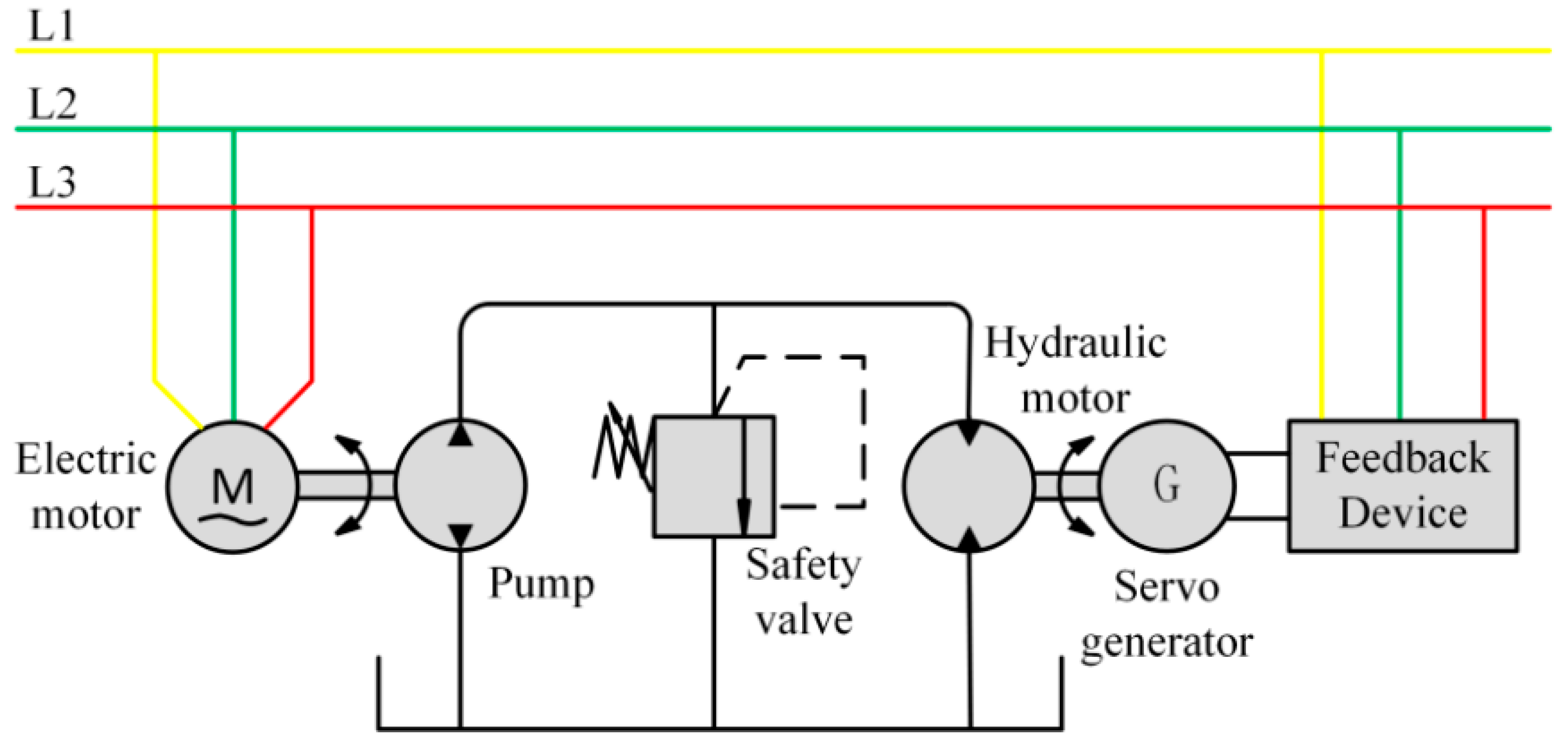
2.1. Analysis of Key Issues

Figure 1 is the schematic diagram of the energy-saving testing system for an electrically compensated power recovery hydraulic pump. The medium discharged by the test pump directly enters the hydraulic motor, which drives the generator to rotate for power generation. The generated electrical energy can be rectified and fed back to the power grid. By adjusting the torque of the servo generator, the outlet pressure of the test pump can be adjusted, achieving performance testing of the test pump under different pressures.
As mentioned earlier, due to the nominal flow rate and pressure of the emulsion motor being smaller than that of the emulsion pump, the system shown in Figure 1 cannot be directly applied to the testing of the emulsion pump; it is necessary to set up a shunt and pressure-reducing structure, and the energy generated by a single emulsion motor is also very limited. Simply, we can connect multiple emulsion motors connected in parallel to the outlet of the emulsion pump to improve the energy recovery efficiency of the system [26]. Therefore, this article proposes an emulsion pump energy-saving testing system as shown in Figure 2.
The outlet of the emulsion pump is connected to an emulsion motor 1 and multiple flow-regulating valves (Figure 2 only shows two as a schematic). The outlet of the flow-regulating valve is connected to an emulsion motor, and the shaft of each emulsion motor is connected to a loading servo generator through a coupling. The generated electricity is fed back to the power grid through a feeding device. Taking Figure 2 as an example, adjusting the loading servo generator 1 can adjust the inlet pressure of emulsion motor 1, as well as the outlet pressure of the emulsion pump and the inlet pressure of the flow control valve. The outlet pressure of flow-regulating valves 1 and 2 can also be adjusted by adjusting the loading of servo generators 2 and 3. During the process of adjusting the inlet and outlet pressure of the flow-regulating valve, the flow through each parallel hydraulic circuit can be adjusted by controlling the opening of the valve core of the flow-regulating valve.
Obviously, the flow-regulating valve is the key to this system. Through review of the literature, it has been found that proportional flow valves are mainly used for flow regulation in hydraulic systems. Proportional flow valves are mainly divided into the flow feedback control type and pressure difference compensation control type [27]. The flow feedback control type is greatly affected by the accuracy and response frequency of the flow sensor, resulting in the poor dynamic response characteristics and stability of this type of valve. There are also two main valve structures for the pressure difference compensation control type, as shown in Figure 3a, which is a traditional pressure difference compensation control flow control valve structure with a proportional throttle valve at the outlet of the pressure-reducing valve. The flow-regulating valve with this structure has a lag in the response of the pressure-reducing valve core. When the inlet and outlet pressure changes, there will be a significant sudden change in flow, which affects the stability of the entire system. Moreover, the proportional solenoid directly drives the throttle valve core, which requires the proportional solenoid to have a very large driving force, making the valve unsuitable for high-pressure working conditions. In addition, traditional pressure differential compensation flow control valve structures are also developed based on oil medium conditions and cannot be applied to high water-based media. As shown in Figure 3b, this is a proportional flow control valve with a pilot stage, mainly composed of three parts: the main valve, pilot valve, and the compensation controller. The flow liquid enters the upper chamber of the main valve core through the channel and variable throttle hole on the main valve core, and flows into the outlet of the main valve through the pilot throttle valve. The pressure sensor at the inlet and outlet of the main valve is used for pressure measurement and transmitted to the compensation controller. Then, the compensation controller changes the control voltage of the proportional solenoid of the pilot valve and adjusts the displacement of the pilot valve core. The change in displacement of the pilot valve core will cause the displacement of the main valve core to change, ultimately regulating the flow rate of the main valve port [28]. This structure has high flow control accuracy and stability, and can adapt to high-pressure working conditions. However, the principle and structure of this valve are relatively complex. The pilot valve core and main valve core both adopt a slide valve structure. Due to the low viscosity of water, leakage occurs easily, which can lead to the valve being unable to function normally under water medium working conditions or with the flow regulation ability being weakened.

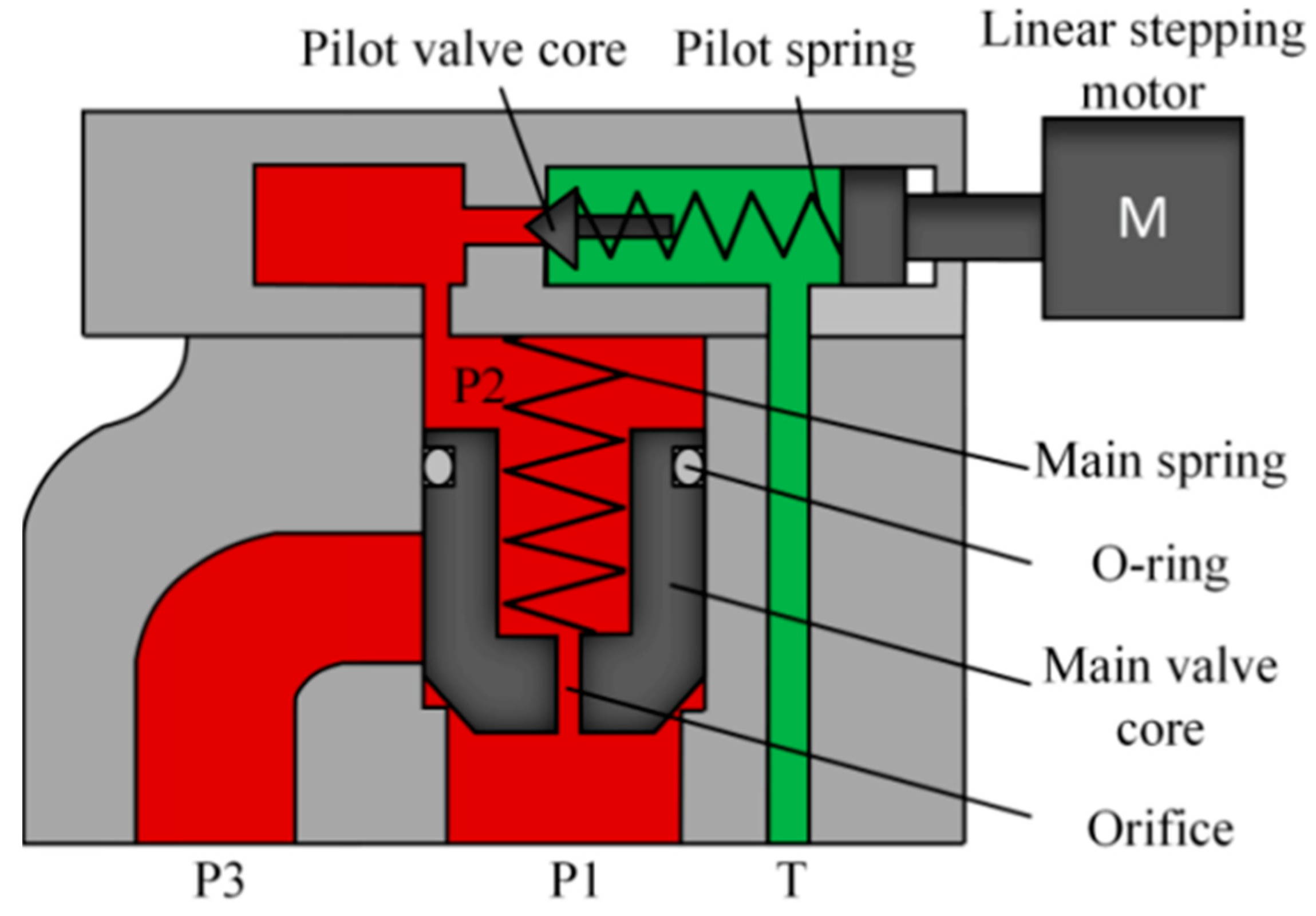
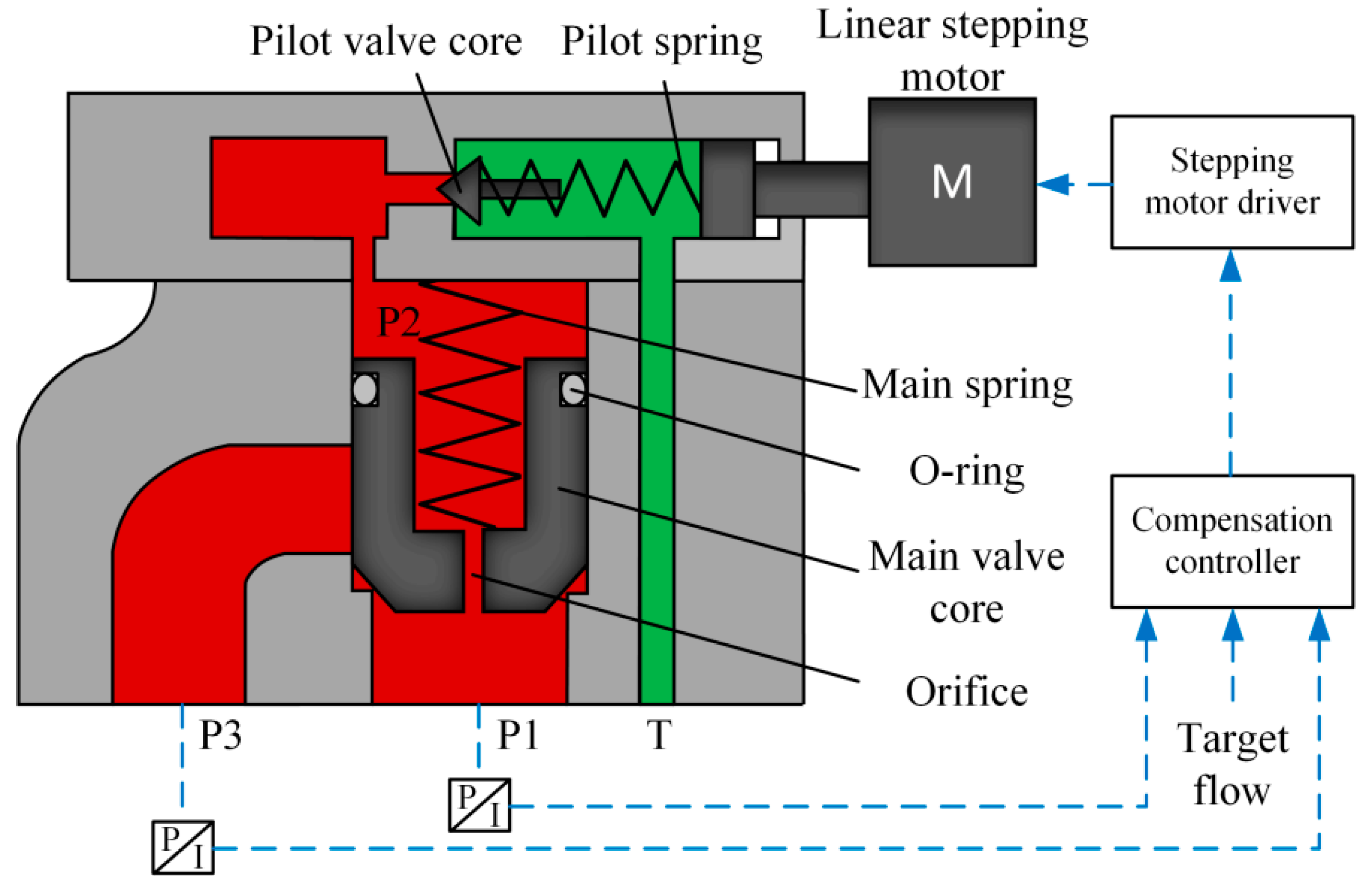
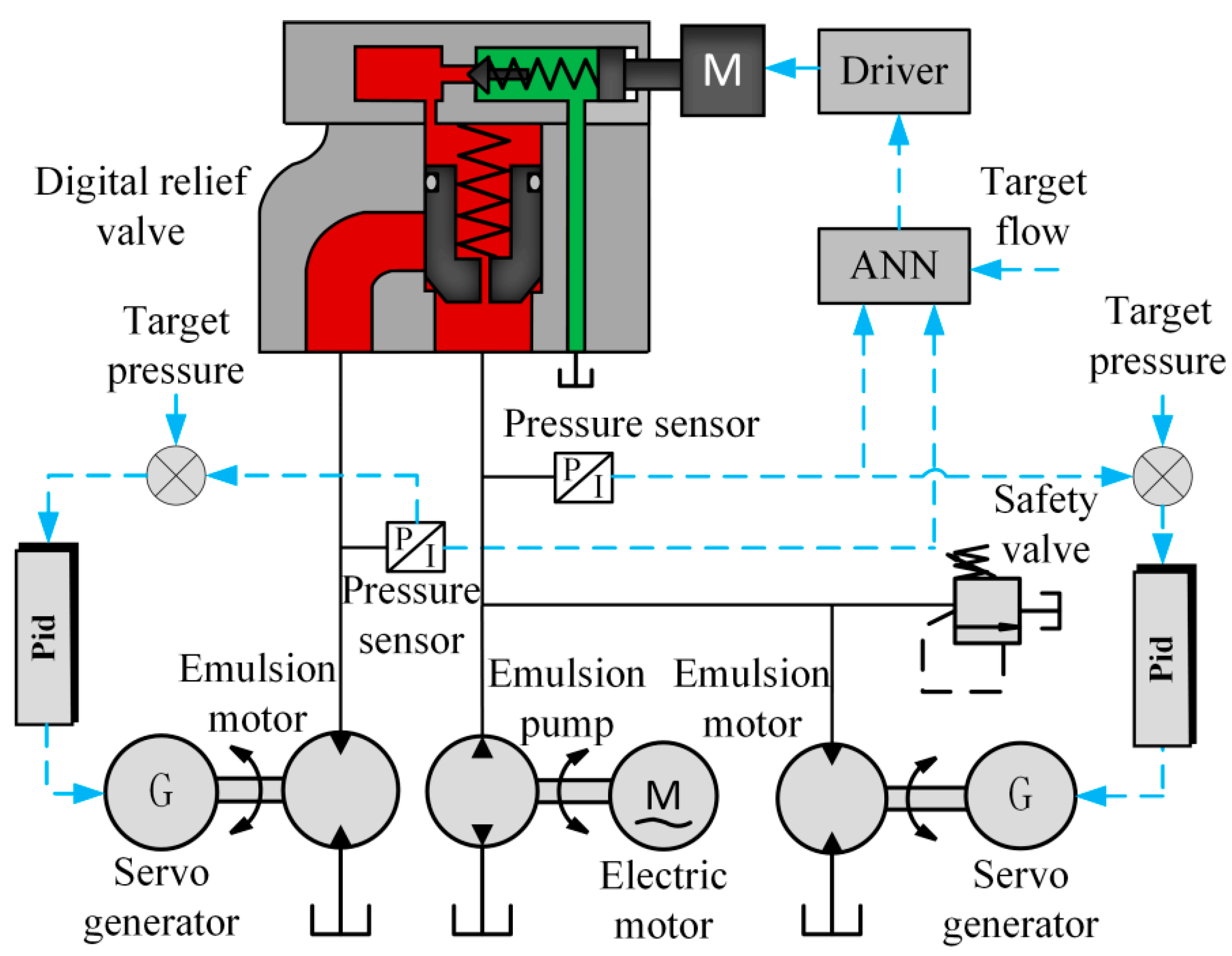
2.2. Proposal of New Solutions

Throughout all the literature and market research, there is very little research on water-based flow control valves, and there is also a lack of products in the market that can be applied to water medium and high-pressure conditions. However, research on water-based pressure control valves is relatively mature, and many scholars have proposed design schemes for water-based proportional relief valves and digital relief valves [29,30]. In order to achieve the normal operation of the emulsion pump energy-saving testing system proposed in this article, a solution using a water-based digital relief valve as a flow control valve was proposed, which mainly utilized the pressure difference flow characteristics of the digital relief valve. Figure 4 shows the structural diagram of a water-based digital relief valve, which consists of a main valve and a pilot valve. The main valve core is equipped with a fixed damping hole, and the compression amount of the pilot valve spring can be adjusted by a linear stepper motor. Firstly, this article analyzes the mathematical model of the digital relief valve to verify that it can be used as a flow-regulating valve.
The balance of forces on the main spool can be expressed as:
p 1 A 1 = p 2 A 2 + k 1 x 1 + x 0 + m g + F b s 1 + F f
where p 1 is the inlet pressure of the main valve core, A 1 is the working area of the lower chamber of the main valve core, p 2 is the upper chamber pressure of the main valve, A 2 is the working area of the upper chamber of the main valve core, k 1 is the stiffness of the main valve spring, x 1 is the displacement of the main valve core, x 0 is the initial compression amount of the main valve spring, m is the quality of the main valve core, F b s 1 is the steady-state hydraulic force of the main valve core, and F f is the frictional force acting on the main valve core.
The steady-state hydraulic force of the main valve core F b s 1 can be calculated using the following formula:
F b s 1 = 2 π · d 1 · p 1 p 3 · C d · x 1 · c o s θ
where d 1 is the diameter of the main valve core, p 3 is the outlet pressure of the overflow valve, C d is the flow coefficient at the main valve core, and θ is the half cone angle of the main valve core.
The friction force on the main valve core F f is mainly generated by the O-ring. According to the literature review [31], the friction force at the O-ring is mainly caused by the deformation of the O-ring and the pressure difference between the two ends of the valve core. This can be expressed by the following formula:
F f = f 1 + f 2
where f 1 is the frictional force generated by the compression deformation of the O-ring, during the action of the valve core the compression deformation rate of the O-ring is almost constant, so it can be considered as a constant value; f 2 is the frictional force generated by the pressure difference between the two ends of the valve core, which can be expressed as a function relationship as follows:
f 2 = F p 1 , p 2
The continuous equation for the flow rate at the main valve port can be expressed as:
Q = C d · π · d 1 · x 1 · s i n θ · 2 p 1 p 3 ρ
where Q is the flow rate through the main valve core.
The pressure of the pilot valve core is also balanced by force, which can be expressed as the following formula:
p 3 A 3 = k 2 x 2 + F b s 2 + f 2  
where A 3 is the acting area of the pilot valve core, k 2 is the stiffness of the pilot spring, x 2 is the pilot spring compression amount, F b s 2 is the steady-state hydraulic force of the pilot core, and f 2   is the friction force on the pilot valve core. Considering the small diameter and flow rate of the pilot valve core, the steady-state hydraulic force and friction force of the pilot valve core can usually be ignored.
Equation (7) can be obtained by combining Equations (1)–(6):
Q = p 1 A 1 p 2 A 2 k 1 x 0 m g f 1 F p 1 , p 2 · c d · π · d 1 · s i n θ k 1 A 3 + 2 π c d d 1 c o s θ p 1 A 3 k 2 x 2 · 2 A 3 p 1 A 3 k 2 x 2 ρ
From the formula, it can be seen that the flow rate of the main valve core through the digital relief valve is determined by the inlet pressure and outlet pressure of the relief valve, as well as the amount of compression of the pilot valve spring. The compression of the pilot spring is numerically equivalent to the extension length of the linear stepper motor shaft. This theoretically proves that the flow regulation of the hydraulic circuit can be achieved by utilizing the pressure difference flow characteristics of the overflow valve. When the inlet and outlet pressure difference changes, the position of the main valve core can be adjusted by adjusting the extension of the pilot valve’s linear stepper motor shaft through the compensation controller, thereby regulating the flow through the main valve core. The working principle is shown in Figure 5.

3. Control Algorithm Development

For this system there are many controlled objects, including various digital overflow valves and the loading servo motors of various emulsion motors. In order to achieve intelligent control of system pressure and flow rate and improve system stability, this article proposes an intelligent control algorithm as shown in Figure 6.
The neural network structure is shown in Figure 7, where P 1 is the inlet pressure of the digital relief valve, P 2 is the outlet pressure of the digital relief valve, q is the flow rate of the main valve core of the digital relief valve, and s is the extension of the linear stepper motor shaft of the digital relief valve.

4. Simulation and Experiment

4.1. Simulation Study

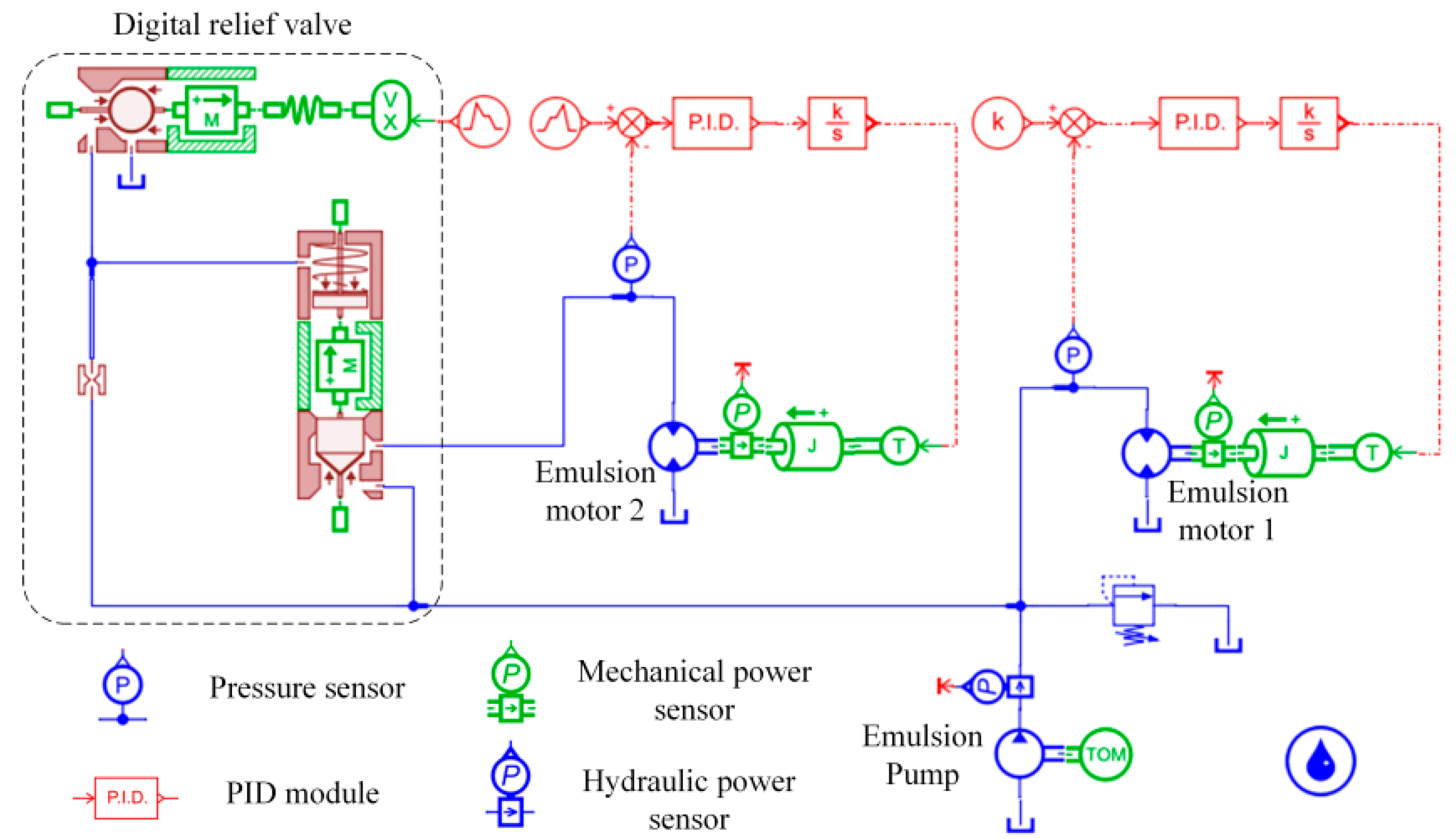
4.1.1. Simulation Model

In order to study the influence of digital relief valve inlet and outlet pressure and linear stepper motor shaft extension on flow rate, this paper builds a simulation model based on AMESim, as shown in Figure 8. At the same time, the simulation model also includes sensors for energy loss and recovery, which are used to test the system’s energy recovery situation.
The model consists of two emulsion motors and a digital flow control valve. The main technical parameters of the simulation model are shown in Table 1.

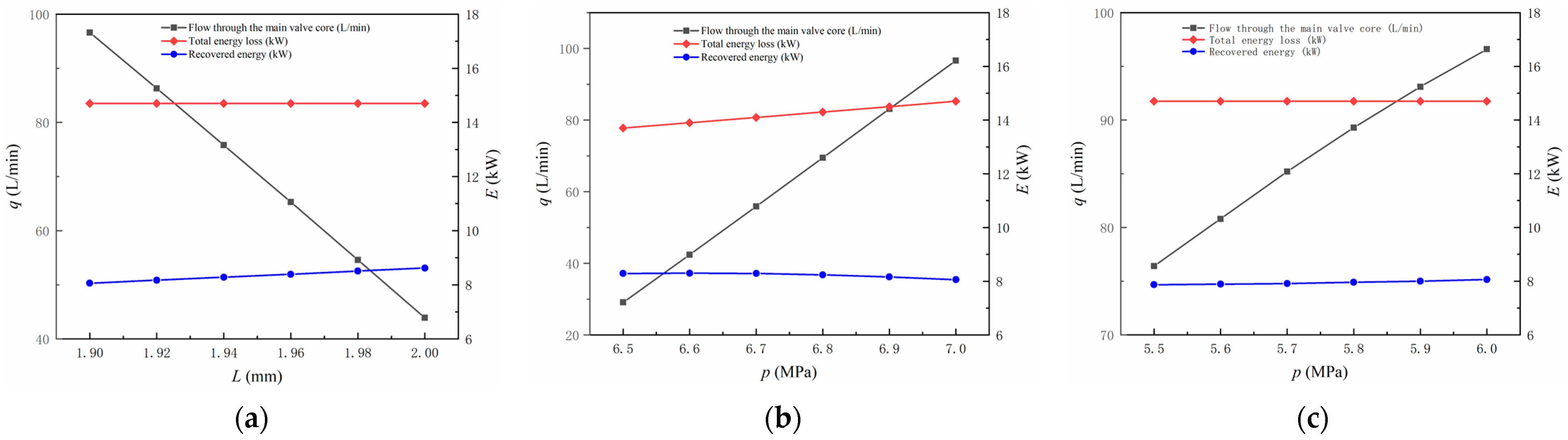
4.1.2. Simulation Result

Firstly, study the influence of the extension of the linear stepper motor shaft of the digital relief valve on the flow rate: Set the target pressures of the inlet and outlet of the digital relief valve to 7 MPa and 6 MPa, respectively. Record the flow rate through the main valve core and the energy consumption and recovery of the entire system under different linear stepper motor shaft extensions. These simulation results are shown in Figure 9a. Secondly, study the influence of inlet pressure of the digital relief valve on flow rate: Set the extension of the linear stepper motor shaft to 1.9 mm, and the outlet target pressure of the digital relief valve to 6 MPa. Record the flow rate through the main valve core of the digital relief valve under different inlet pressures, as well as the energy consumption and recovery of the entire system, as shown in Figure 9b. Thirdly, study the influence of the outlet pressure of the digital relief valve on the flow rate: Set the extension of the linear stepper motor shaft to 1.9 mm, and set the inlet target pressure of the digital relief valve to 7 MPa. Record the flow rate through the main valve core of the digital relief valve under different outlet pressures, as well as the energy consumption and recovery of the entire system, as shown in Figure 9c. From the flow curves under three operating conditions, it can be seen that, as analyzed by the mathematical model above, the inlet and outlet pressure of the digital relief valve and the extension of the linear stepper motor shaft both have an impact on the flow through the main valve core. From the energy curve, it can be seen that the changes in inlet and outlet pressure of the digital relief valve and the extension of the linear stepper motor shaft have a slight impact on the energy recovery efficiency of the system. However, the energy recovery efficiency of the system has exceeded 53%, achieving good results.

4.2. Experimental Study
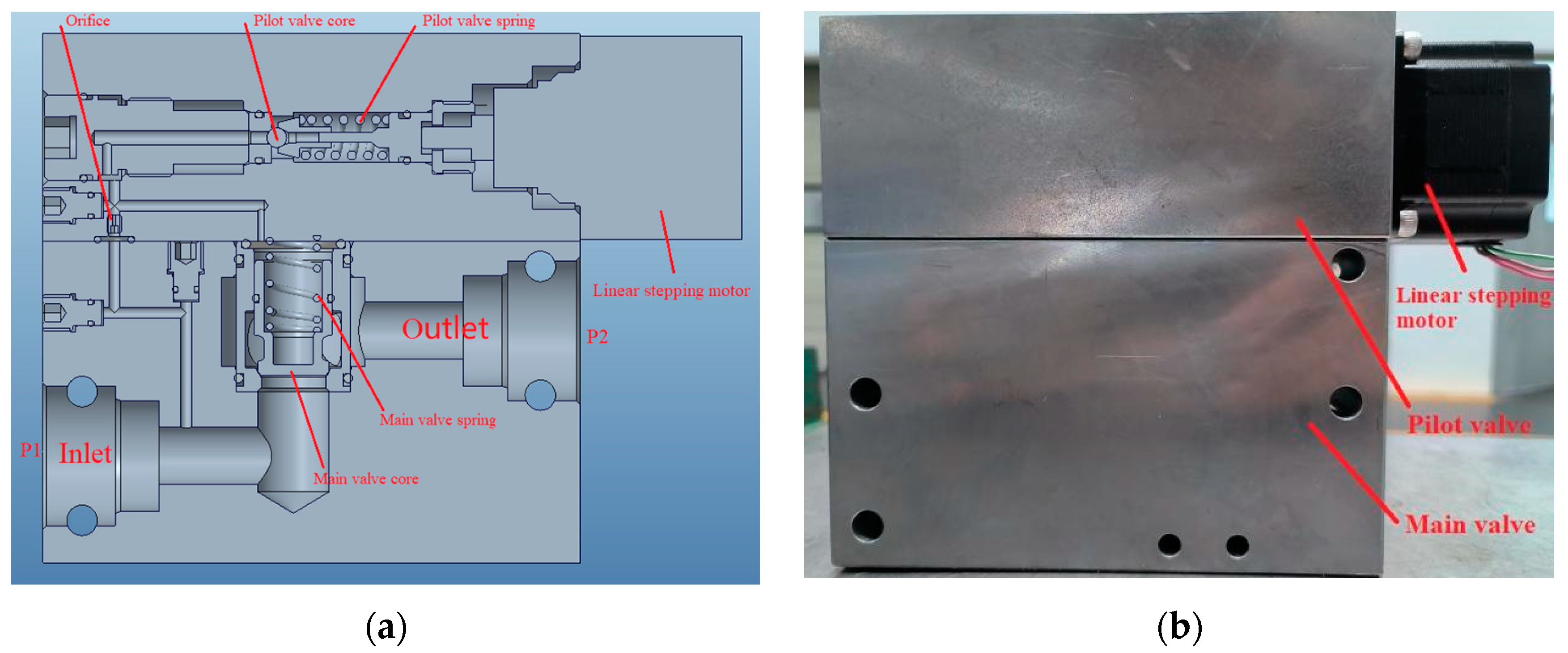
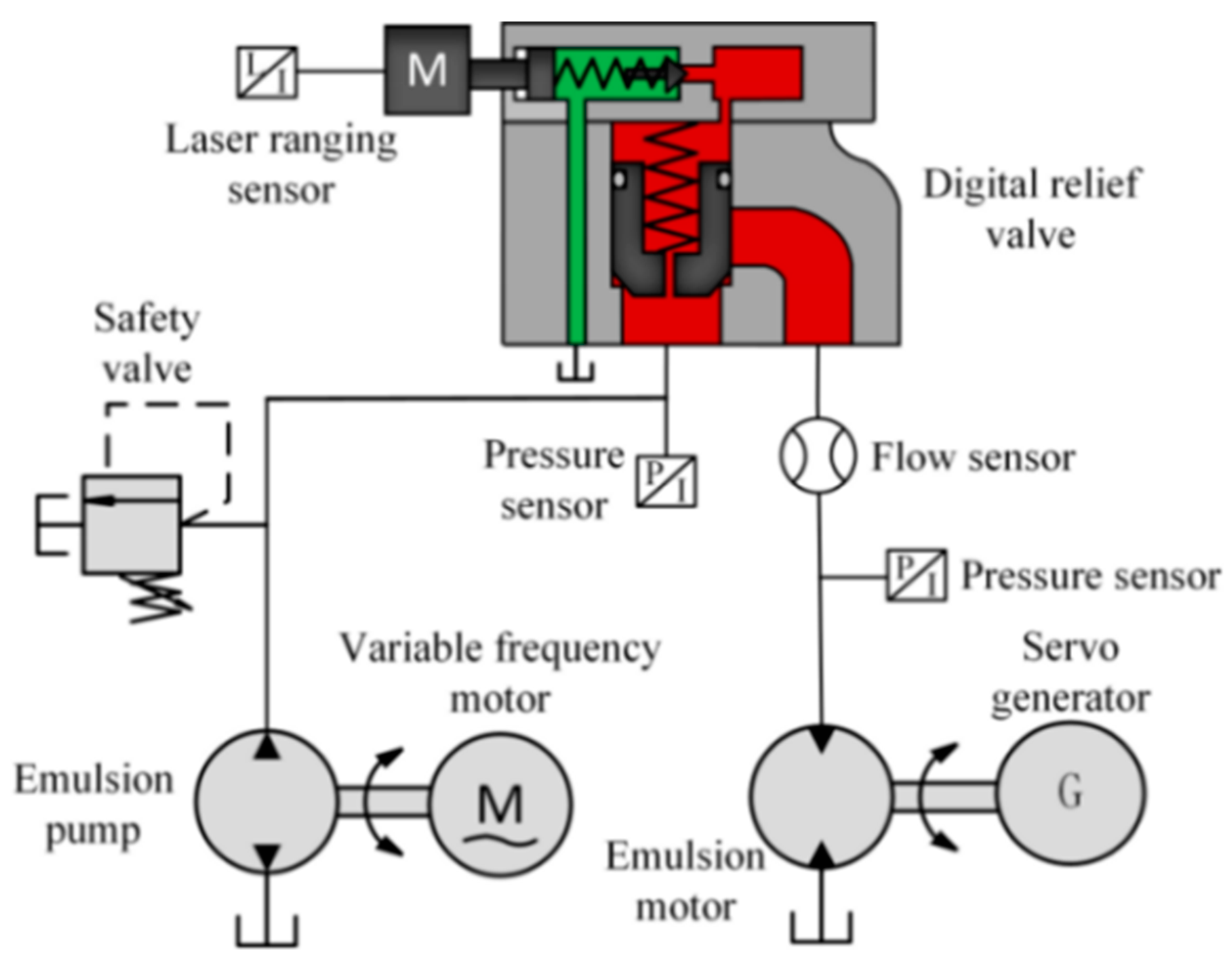
4.2.1. Test Device

In order to further verify the feasibility of the proposed system and algorithm, this article conducted further verification through experiments. Firstly, this article has designed and developed a water-based digital relief valve as shown in Figure 10, whose main structural parameters are consistent with the simulation model mentioned above.
Before the experiment, in order to achieve precise flow control, it is necessary to collect data on the inlet and outlet pressure of the digital relief valve, the flow rate of the main valve core, and the extension of the stepper motor shaft for training and prediction. In order to efficiently obtain training data, this article designed an experimental device as shown in Figure 11. The emulsion pump here is driven by a variable frequency motor to regulate the output flow rate of the pump. The digital overflow valve is connected directly to the outlet of the emulsion pump, and there is a pressure sensor connected to each inlet and outlet of the digital overflow valve for testing the inlet pressure of the emulsion motor. The inlet of the emulsion motor is connected to a flow sensor for measuring the flow through the main valve core of the digital overflow valve, and the extension of the linear stepper motor shaft is recorded through a laser-ranging sensor. In order to improve the testing accuracy high-precision sensors are used, and the measurement error is less than 0.5%.
Adjust the frequency of the variable frequency motor through the frequency converter, and adjust the flow rate through the digital overflow valve to 50 L/min, 60 L/min, 70 L/min, and 80 L/min. By adjusting the torque of the loading servo motor, the inlet pressure of the emulsion motor can be adjusted to 4 MPa, 8 MPa, 12 MPa, and 16 MPa, respectively. Due to the constant flow rate of the tested pump, the inlet pressure of the overflow valve can be adjusted by adjusting the extension of the linear stepper motor shaft. Adjust the pressure difference between the inlet and outlet of the digital relief valve to 0.6 MPa, 0.8 MPa, 1 MPa, and 1.2 MPa, and record the data results of each sensor, as shown in Table 2.
Train and validate the data in Table 2 using the MATLAB neural network toolbox. Here, the number of hidden layers is set to one layer, and the number of hidden layer neurons is set to 7. The training data set, validation data set, and test data set are set to 70%, 15%, and 15%, respectively. The training results are shown in Figure 12. The training results indicate that the constructed artificial neural network can accurately complete the prediction. Finally, generate and save the training results into code for the development of control algorithms.

4.2.2. Experimental Results and Analysis

Considering that the author’s laboratory only has a set of loading servo motors and energy feedback devices, a testing platform is built as shown in Figure 13. A proportional relief valve is connected in parallel at the inlet of the digital relief valve to regulate the pressure at the inlet. The flow rate of the emulsion pump in this testing platform is 125 L/min. The output shaft of the emulsion motor is connected to a loading servo generator, and the generated electrical energy is fed back to the power grid through a rectifier device.
Given the limitations of the experimental conditions, this testing platform focuses on verifying the proposed pressure and flow control algorithms. Firstly, adjust the proportional relief valve and load the servo generator separately, and adjust the inlet and outlet pressures of the digital relief valve to 5.8 MPa and 5 MPa, respectively. Set the target flow rate of the main valve core of the digital overflow valve to 72 L/min, and calculate the extension of the linear stepper motor shaft using an artificial neural network algorithm, so that the linear stepper motor is controlled and operates at the calculated value. Subsequently, through intelligent control algorithms, the inlet and outlet pressures of the speed control valve are adjusted to 5.5 MPa and 6.5 MPa, and the target flow rate of the entire circuit is always 72 L/min. The changes in various system parameters during this process were recorded, as shown in Figure 14.
From the test results, we can see that the pressure adjustment of the system has almost no error, and the flow rate through the main valve core remains basically unchanged after the pressure change at the inlet and outlet of the overflow valve, maintaining about 68 L/min. This verifies that the flow control algorithm proposed in this article, which combines the pressure difference flow characteristics of water-based digital relief valves with neural network predictive intelligent control, can achieve accurate flow control. However, there is an error of about 5% between the actual traffic and the target traffic. In analyzing the reasons, this is mainly due to the accuracy error of the flow sensor and the small number of samples used for neural network training data.

5. Summary

This article analyzes the difficulties faced in achieving energy-saving testing of emulsion pumps under the working condition of emulsion as the transmission medium, and proposes a new energy-saving testing system for emulsion pumps. In order to improve the energy recovery efficiency of the entire testing system, the system adopts multiple emulsion motors in parallel, and proposes the use of the pressure difference flow characteristics of digital relief valves combined with an artificial neural network predictive control algorithm to achieve flow control of each parallel circuit. This method overcomes the disadvantage of having flow-regulating valves in oil-based hydraulic systems that cannot be applied in water-based hydraulic systems. The feasibility and progressiveness of the proposed test system and control algorithm are verified by building a simulation and test system. The simulation and test results show that the proposed system has high energy recovery efficiency and pressure and flow control accuracy. This provides an efficient and feasible solution for the energy-saving testing of emulsion pumps.

Author Contributions

Conceptualization, J.T. and W.L.; methodology, W.L.; software, H.W.; validation, J.T. and H.W.; formal analysis, W.L.; investigation, W.L.; resources, J.T.; data curation, W.L.; writing—original draft preparation, W.L.; writing—review and editing, W.L.; visualization, X.Y.; supervision, R.Z.; project administration, J.L.; funding acquisition, J.T. All authors have read and agreed to the published version of the manuscript.

Funding

The authors appreciate the fiscal encouragement from the Fundamental Research Funds for the Central Universities under Grant (2022JCCXJD02 and 2022YJSJD09), the Ministry of Education (EW202180222), and the National Natural Science Foundation of China under Grant (51774293).

Data Availability Statement

Not applicable.

Conflicts of Interest

The authors declare no conflict of interest.

References

  1. Randers, J.; Goluke, U. An earth system model shows self-sustained thawing of permafrost even if all man-made GHG emissions stop in 2020. Sci. Rep. 2020, 10, 18456. [Google Scholar] [CrossRef]
  2. Kirikkaleli, D.; Sowah, J.K., Jr. Time-frequency dependency of temperature and sea level: A global perspective. Environ. Sci. Pollut. Res. 2021, 28, 58787–58798. [Google Scholar] [CrossRef] [PubMed]
  3. McIlwaine, N.; Foley, A.M.; Morrow, D.J.; Al Kez, D.; Zhang, C.; Lu, X.; Best, R.J. A state-of-the-art techno-economic review of distributed and embedded energy storage for energy systems. Energy 2021, 229, 120461. [Google Scholar] [CrossRef]
  4. Elsaid, A.M. A novel design, implementation and performance evaluation of the first electronic expansion ejector for energy saving of a mini split air conditioner controlled by inverter. Energ. Convers. Manag. 2022, 260, 115603. [Google Scholar] [CrossRef]
  5. Du, T.; Nie, W.; Chen, D.; Xiu, Z.; Yang, B.; Liu, Q.; Guo, L. CFD modeling of coal dust migration in an 8.8-m-high fully mechanized mining face. Energy 2020, 212, 118616. [Google Scholar] [CrossRef]
  6. Wang, J.; Wang, Z. Systematic principles of surrounding rock control in longwall mining within thick coal seams. Int. J. Min. Sci. Technol. 2019, 29, 65–71. [Google Scholar] [CrossRef]
  7. Tian, J.; Liu, W.; Wang, H. Testing Method for Intelligent Loading of Mining Emulsion Pump Based on Digital Relief Valve and BP Neural Network Control Algorithm. Machines 2022, 10, 896. [Google Scholar] [CrossRef]
  8. Li, R.; Wang, D.; Wei, W.; Li, S. Analysis of the Movement Characteristics of the Pump Valve of the Mine Emulsion Pump Based on the Internet of Things and Cellular Automata. Mob. Inf. Syst. 2021, 2021, 9032769. [Google Scholar] [CrossRef]
  9. Ho, T.H.; Ahn, K.K. Design and control of a closed-loop hydraulic energy-regenerative system. Autom. Constr. 2012, 22, 444–458. [Google Scholar] [CrossRef]
  10. Wang, T.; Wang, Q. Efficiency analysis and evaluation of energy-saving pressure-compensated circuit for hybrid hydraulic excavator. Autom. Constr. 2014, 47, 62–68. [Google Scholar] [CrossRef]
  11. Sun, J.; Wang, Y.; Xu, S.; Wang, S.; Wang, Y. Performance prediction of hydraulic energy recovery (HER) device with novel mechanics for small-scale SWRO desalination system. Desalination 2009, 249, 667–671. [Google Scholar] [CrossRef]
  12. Lin, T.; Huang, W.; Ren, H.; Fu, S.; Liu, Q. New compound energy regeneration system and control strategy for hybrid hydraulic excavators. Autom. Constr. 2016, 68, 11–20. [Google Scholar] [CrossRef]
  13. Banaszek, A.; Petrovic, R.; Andjelkovic, M.; Radosavljevic, M. Efficiency of a Twin-Two-Pump Hydraulic Power Pack with Pumps Equipped in Constant Pressure Regulators with Different Linear Performance Characteristics. Energies 2022, 15, 8100. [Google Scholar] [CrossRef]
  14. Banaszek, A. Identification of optimal efficiency exploitation conditions of axial-piston hydraulic motor A2FM type using Artificial Neural Network algorithms. Procedia Comput. Sci. 2021, 192, 1532–1540. [Google Scholar] [CrossRef]
  15. Gong, J.; Zhang, D.; Guo, Y.; Liu, C.; Zhao, Y.; Hu, P.; Quan, W. Power control strategy and performance evaluation of a novel electro-hydraulic energy-saving system. Appl. Energ. 2019, 233, 724–734. [Google Scholar] [CrossRef]
  16. Xiao, W.; Xu, J.; Lv, X. Establishing a georeferenced spatio-temporal database for Chinese coal mining accidents between 2000 and 2015. Geomat. Nat. Hazards Risk 2019, 10, 242–270. [Google Scholar] [CrossRef]
  17. Zhang, Q.; Zhang, J.; Wu, Z.; Chen, Y. Overview of Solid Backfilling Technology Based on Coal-Waste Underground Separation in China. Sustainability 2019, 11, 2118. [Google Scholar] [CrossRef]
  18. Muduli, L.; Mishra, D.P.; Jana, P.K. Optimized Fuzzy Logic-Based Fire Monitoring in Underground Coal Mines: Binary Particle Swarm Optimization Approach. IEEE Syst. J. 2020, 14, 3039–3046. [Google Scholar] [CrossRef]
  19. Liu, Q.; Peng, Y.; Li, Z.; Zhao, P.; Qiu, Z. Hazard identification methodology for underground coal mine risk management—Root-State Hazard Identification. Resour. Policy 2021, 72, 102052. [Google Scholar] [CrossRef]
  20. Wang, W.; Liang, Y. Prevention and Control Technology for Harmful Toxic Gas Intrusion in High-Fire-Hazard-Risk Areas of Close-Distance Coal Seams. J. Chem. 2020, 2020, 9040825. [Google Scholar] [CrossRef]
  21. Zhou, R.; Meng, L.; Yuan, X.; Qiao, Z. Research and Experimental Analysis of Hydraulic Cylinder Position Control Mechanism Based on Pressure Detection. Machines 2022, 10, 1. [Google Scholar] [CrossRef]
  22. Li, Y.; Zhu, Z.; Chen, G.; Cao, G. A novel energy regeneration system for emulsion pump tests. J. Mech. Sci. Technol. 2013, 27, 1155–1163. [Google Scholar]
  23. Xu, Q.; Huang, Y. Development and Application of Non-Circular Gear Emulsion Motor. Adv. Mater. Res. 2011, 317, 134–137. [Google Scholar] [CrossRef]
  24. Zhang, C.; Zhao, S.; Guo, G.; Dong, W. Modeling and Simulation of Emulsion Pump Station Pressure Control System Based on Electro-Hydraulic Proportional Relief Valve. J. Appl. Mech. Mater. 2012, 190, 860–864. [Google Scholar] [CrossRef]
  25. Jia, T.; Wu, Z.; Wang, J.; Feng, R.; Qin, Y. Design and Performance Analysis of Digital Pressure Relief Valve of Water-Based Hydraulic. J. Appl. Mech. Mater. 2013, 387, 369–373. [Google Scholar] [CrossRef]
  26. Banaszek, A.; Petrovic, R. Problem of Non Proportional Flow of Hydraulic Pumps Working with Constant Pressure Regulators in Big Power Multipump Power Pack Unit in Open System. Teh. Vjesn. 2019, 26, 294–301. [Google Scholar]
  27. Wang, H.; Wang, X.; Huang, J.; Quan, L. Flow Control for a Two-Stage Proportional Valve with Hydraulic Position Feedback. Chin. J. Mech. Eng. 2020, 33, 93. [Google Scholar] [CrossRef]
  28. Xiong, X.; Huang, J. Performance of a flow control valve with pilot switching valve. Proc. Inst. Mech. Eng. Part I 2018, 232, 178–194. [Google Scholar] [CrossRef]
  29. Zeng, Q.; Tian, M.; Wan, L.; Dai, H.; Yang, Y.; Sun, Z.; Lu, Y.; Liu, F. Characteristic Analysis of Digital Large Flow Emulsion Relief Valve. Math. Probl. Eng. 2020, 2020, 5820812. [Google Scholar] [CrossRef]
  30. Wan, L.; Dai, H.; Zeng, Q.; Lu, Z.; Sun, Z.; Tian, M.; Lu, Y. Characteristic Analysis of Digital Emulsion Relief Valve Based on the Hydraulic Loading System. Shock Vib. 2020, 2020, 8866919. [Google Scholar] [CrossRef]
  31. Zhang, J.; Xie, J. Investigation of Static and Dynamic Seal Performances of a Rubber O-Ring. J. Tribol. 2018, 140, 042202. [Google Scholar] [CrossRef]
Figure 1. Electric compensation power recovery hydraulic pump testing system.
Processes 11 02632 g001
Figure 2. Energy saving testing system for emulsion pumps.
Processes 11 02632 g002
Figure 3. Pressure difference compensation flow control valve. (a) Proportional flow control valve; (b) Proportional flow control valve with pilot stage.
Processes 11 02632 g003
Figure 4. Structural diagram of water-based digital relief valve.
Processes 11 02632 g004
Figure 5. Schematic diagram of flow control based on digital relief valve.
Processes 11 02632 g005
Figure 6. Intelligent pressure and flow control algorithms.
Processes 11 02632 g006
Figure 7. Artificial neural network structure diagram.
Processes 11 02632 g007
Figure 8. Simulation Model.
Processes 11 02632 g008
Figure 9. Flow curve and system energy curve of digital relief valve under different working conditions. (a) Influence of axis extension of linear stepping motor; (b) Influence of digital relief valve inlet pressure; (c) Influence of digital relief valve outlet pressure.
Processes 11 02632 g009
Figure 10. Three-dimensional model and prototype of water-based digital relief valve. (a) Three-dimensional model; (b) Prototype model.
Processes 11 02632 g010
Figure 11. Experimental device for obtaining training data.
Processes 11 02632 g011
Figure 12. Training results. (a) Performance curves of model error; (b) Regression curves of model error.
Processes 11 02632 g012
Figure 13. Test platform.
Processes 11 02632 g013
Figure 14. Digital overflow inlet and outlet pressure and main valve core flow rate variation curve.
Processes 11 02632 g014
Table 1. Main technical parameters of simulation model.
Parameter NameValue
Pilot valve seat diameter (mm)5.5
Pilot valve spool diameter (mm)20
Pilot valve spring stiffness (N/mm)65
Orifice diameter (mm)0.8
Orifice length (mm)5
Diameter of the lower end of the main valve core (mm)14
Diameter of the upper end of the main valve core (mm)16
Half cone angle of main valve core (°)30
Emulsion motor Volumetric efficiency0.7
Emulsion motor Mechanical efficiency0.9
Emulsion pump flow rate (L/min)125
Load Moment of inertia (kg·m2)0.01
Proportional gain of PID controller10
Derivative gain of PID controller0.5
Table 2. Measured data.
Outlet Pressure of Overflow Valve (MPa)Flow (L/min)Pressure Difference between Inlet and Outlet of Overflow Valve (MPa)
0.60.811.2
Shaft Extension of Linear Stepping Motor (mm)
4501.141.201.241.29
601.131.181.221.28
701.111.161.211.26
801.091.141.191.24
8502.362.412.452.53
602.342.392.432.52
702.322.372.422.50
802.302.352.402.48
12503.563.613.683.74
603.543.593.653.72
703.533.583.633.70
803.513.563.613.69
16504.764.814.864.91
604.754.794.854.90
704.734.784.844.88
804.714.764.824.86
Disclaimer/Publisher’s Note: The statements, opinions and data contained in all publications are solely those of the individual author(s) and contributor(s) and not of MDPI and/or the editor(s). MDPI and/or the editor(s) disclaim responsibility for any injury to people or property resulting from any ideas, methods, instructions or products referred to in the content.

