Article

Simulation Study on Dynamic Characteristics of the Chain Drive System for Mining Scraper Conveyor Driven by the Permanent Magnet Synchronous Motor

School of Mechanical and Electrical Engineering, China University of Mining & Technology (Beijing), Beijing 100083, China
*
Author to whom correspondence should be addressed.
Processes 2024, 12(1), 165; https://doi.org/10.3390/pr12010165
Submission received: 12 December 2023 / Revised: 6 January 2024 / Accepted: 8 January 2024 / Published: 10 January 2024
(This article belongs to the Topic New Advances in Mining Technology)

Abstract

:
The chain drive system represents a critical subsystem within the scraper conveyor. This paper proposes a joint simulation model for the drive system of the scraper conveyor, driven by the permanent magnet synchronous motor, in order to conduct a comprehensive analysis of the dynamic characteristics of the chain drive system during the operational process. Firstly, the dynamic simulation model for the mining scraper conveyor’s chain drive system was established in ADAMS, taking into account its structural characteristics. Then, the mathematical model of the permanent magnet synchronous motor was established using the coordinate transformation theory, and the speed controller based on vector control was designed by using the theory related to sliding mode control. The coupling relationship between the chain drive system of the scraper conveyor and the permanent magnet synchronous motor drive system was investigated. Finally, a joint simulation model of the mechanical system and motor control system was created using ADAMS (View 2019) and MATLAB/Simulink (2020a). The dynamic characteristics of the chain drive system were analyzed, and the three typical working conditions of no load, half load, and rated load were considered. The results show that the contact force between the flat ring and the sprocket undergoes an initial increase, followed by a decrease, and finally another increase. As the load increases from no load to full load, there is a marked increase in the contact force between the loaded side chainrings. Due to the polygon effect, both the speed curve of the permanent magnet drive motor and the contact force curve between the ring chains exhibit periodic fluctuations. The research in this paper provides an idea for the coupling analysis of the scraper conveyor electromechanical system.

Graphical Abstract

1. Introduction

The longwall fully mechanized mining technology is presently the most efficient and extensively employed technique in coal mining. The shearer, hydraulic support, and scraper conveyor are the main mechanical devices for coal mining [1,2]. The scraper conveyor serves as the core transportation equipment for fully mechanized mining operations. Its major function is to load and transport coal cut by the shearer, and it is also the track of the shearer as well as the fulcrum of the hydraulic support. The safety and mining efficiency of the fully mechanized mining face are greatly influenced by the comprehensive technical level of its drive and transmission systems [3,4].
The chain drive system is a crucial component of the scraper conveyor, exposed to intricate operation conditions, fluctuations in loads, and severe working environments. The chainring is vulnerable to significant impacts, leading to instability in the chain drive system [5,6]. Furthermore, the stability of the scraper conveyor drive motor control subsystem is also affected by operational factors such as high starting torque, imbalanced load, and frequent stops and starts [7,8,9]. Therefore, investigating the dynamic properties of the chain drive system in various operational scenarios and analyzing the operational principles of the motor in the drive control system hold immense importance and value in enhancing the overall performance of the scraper conveyor and advancing the efficiency of fully mechanized mining transportation.
Researchers have undertaken studies to enhance the efficiency of scraper conveyors and ensure the stability of chain transmission system operation. Ren et al. [10] developed a coupling analysis model utilizing EDEM–ADAMS software, which is based on the principles of the multibody dynamics theory and discrete element method. This model is capable of accurately modeling the transportation process of coal employing scraper conveyors. The study examined different loads and eccentric loads in order to determine the laws governing the changes in speed and contact force between the chainring and scraper. The research findings provide a specific reference for improving the efficiency of the scraper conveyor in transportation and ensuring the stability of the chain transmission system. Zhang et al. [11] analyzed the dynamic contact properties of the chain drive system during the process of engagement. Based on this premise, a technique for calculating the distribution of tension in the chain transmission system is suggested, and the pattern of tension distribution is determined, offering a guideline for monitoring the changes in the tension of the ring chain. Jiang et al. [12] constructed a test bench to assess the dynamic performance of a scraper conveyor. They gathered vibration data from the reducer at various chain speeds, weights, and topographical conditions. The dynamic features of the scraper conveyor were then analyzed using a frequency domain analysis. The findings indicate that the secondary meshing frequency of the reducer has a substantial impact on the operational stability of the chain drive system. Lu et al. [13] developed a coupled vibration model for the chain drive system of the scraper conveyor. They analyzed the longitudinal and torsional vibration characteristics of the transmission system. This analysis was conducted through numerical simulation. The researchers identified the area affected by the torsional vibration of the scraper and provided a theoretical basis for optimizing the parameters of the scraper and predicting faults in the chain drive system. Dai et al. [14] thoroughly examined the uncertainties associated with modeling, chain stiffness identification, and random load disturbances. They proposed an adaptive control approach for controlling the tension of a scraper conveyor. They developed a differential tension model for the scraper conveyor chain drive system and designed an adaptive tension controller. Experiments were conducted to verify the efficacy of the suggested controller for managing a random load. This provides a theoretical foundation for tension control in the chain drive system of the scraper conveyor. Jiang et al. [15] developed a simulation model that combines multibody dynamics and the discrete element method to analyze the chain drive system in a coal mine. They specifically focused on the coal transport process of the scraper conveyor. By studying the system under impact load and various coal-dropping conditions, they determined that the primary cause of failure in the chain drive system was longitudinal vibration. The magnitude of the impact is directly related to the degree of caking in huge coal, which serves as an indication for enhancing the dependability of the scraper conveyor’s chain drive system. Yuan et al. [16] developed a dynamic model of a scraper conveyor using the multibody system theory and finite segmentation method. They considered both horizontal and vertical bending and used MATLAB/Simulink for the simulation and analysis. The study investigated the impact of the bending chain on the dynamic performance under various working conditions. The findings provide a theoretical foundation for predicting and evaluating the dynamic performance of scraper conveyors.
The permanent magnet synchronous motor (PMSM) is a type of motor that utilizes permanent magnet excitation. The permanent magnet can produce a permanent magnetic field without an excitation current. It has the advantages of a simple structure, reliable operation, high efficiency, and power density. With the advancements in rare earth permanent magnet materials, power electronics technology, and modern control theory, permanent magnet drive technology has become extensively utilized in industries such as wind power generation, industrial robots, and rail transit [17,18,19,20]. As a new type of power execution terminal, the PMSM is capable of producing not only low-speed and high-torque output, but also satisfying the requirement for a high starting torque. It has vast research prospects and significant potential for its development in the fields of mining equipment, transportation, and lifting equipment in coal mines. Consequently, scholars have conducted theoretical and experimental research on permanent magnet drive technology for mining equipment. Sheng et al. [21] proposed a control system for a shearer that is powered by a low-speed and high-torque PMSM. They created a mathematical model to analyze the variation in the cutting load between the motor and shearer. To implement a sensorless control strategy, utilizing the sliding mode control theory, they designed a sliding mode observer. Additionally, they introduced a fuzzy adaptive control algorithm to adjust the switching gain. The simulation findings indicate that the novel control approach has a favorable impact on the permanent magnet drive system of the shearer. Lu et al. [22] designed a MATLAB/Simulink model for a PMSM direct-drive scraper conveyor. They also proposed a composite sliding mode control method that takes into account the load characteristics. This method enhances the stability of the scraper conveyor’s operation and minimizes the impact load on the PMSM control system. Ju et al. [23] developed a nonlinear feedback controller to effectively reduce the torsional vibration of the main drive system of a scraper conveyor that is directly powered by a high-power PMSM. The nonlinear dynamics model of the main drive system of the conveyor is constructed using the Lagrange–Maxwell principle. The effectiveness of the created controller is then confirmed using numerical simulation. The research findings serve as a guide for implementing the PMSM in the domain of big electromechanical machinery. Sheng et al. [24] introduced a permanent magnet semidirect transmission method for the shearer. The research findings enhance the understanding and mitigation of the faults in shearers operating in harsh environments, as well as inform the development of efficient control systems. Chen et al. [25] focused their research on the permanent magnet semidirect drive system of the shearer. They developed a nonlinear dynamic model of the three-stage drive system and examined the complexity of the shearer’s work in real working conditions. They investigated the gear meshing force and proposed a time-varying residual strength model to adjust for random loads. This study offers a framework for enhancing the dependability of the cutting gear in a permanent magnet semidirect drive shearer. Li et al. [26] proposed a permanent magnetic eddy current drive system for scraper conveyors, established the mathematical model of the drive system, analyzed the characteristics of the drive system through theory and experiment, and optimized the structure of the coupler in the system, which improved the transmission efficiency and reduced the shock vibration in the startup of the scraper conveyor.
The heavy scraper conveyors that are currently widely used are generally of a large volume and mass, making it challenging to convert them into test beds under laboratory conditions to study the dynamic characteristics of the drive and transmission systems. Additionally, conducting underground experiments is constrained by various limiting factors such as inadequate safety measures, unfavorable working conditions, and high expenses [27]. A simulation analysis can effectively avoid the limitations of the above problems, which is a valuable research idea. However, due to the limitations of the multibody dynamics software in generating the control module for the PMSM, and the inability of the electrical control system simulation software to simulate the complicated operation processes of the chain drive system, it is unfeasible to comprehensively analyze the dynamic characteristics of the permanent magnet drive scraper conveyor’s chain drive system from a single mechanical or electrical point of view. Therefore, this paper presents a dynamic simulation model for the chain transmission system of a scraper conveyor used in mining. It also develops a control system model for the PMSM and proposes a joint simulation method for the driving transmission system of the scraper conveyor using MATLAB/Simulink–ADAMS. This study aims at investigating the dynamic properties of the chain drive system in the scraper conveyor operated by a PMSM across different operating conditions. Additionally, the change law of the contact force between the flat ring and the vertical ring, as well as between the flat ring and the sprocket, is analyzed. From the perspective of safe and stable coal mine production, the research results are expected to provide a reference for the running condition monitoring and structural optimization of the chain drive system of the scraper conveyor.
The structure of the paper is as follows: The establishment process of the scraper conveyor chain drive system model is elaborated in Section 2. The design of a speed controller for the PMSM based on vector control is explained in Section 3. Section 4 provides the simulation and analysis results of a MATLAB/Simulink–ADAMS coupling model under three different conditions. Ultimately, the last section provides a concise overview of the research.

2. Model of Scraper Conveyor Chain Drive System

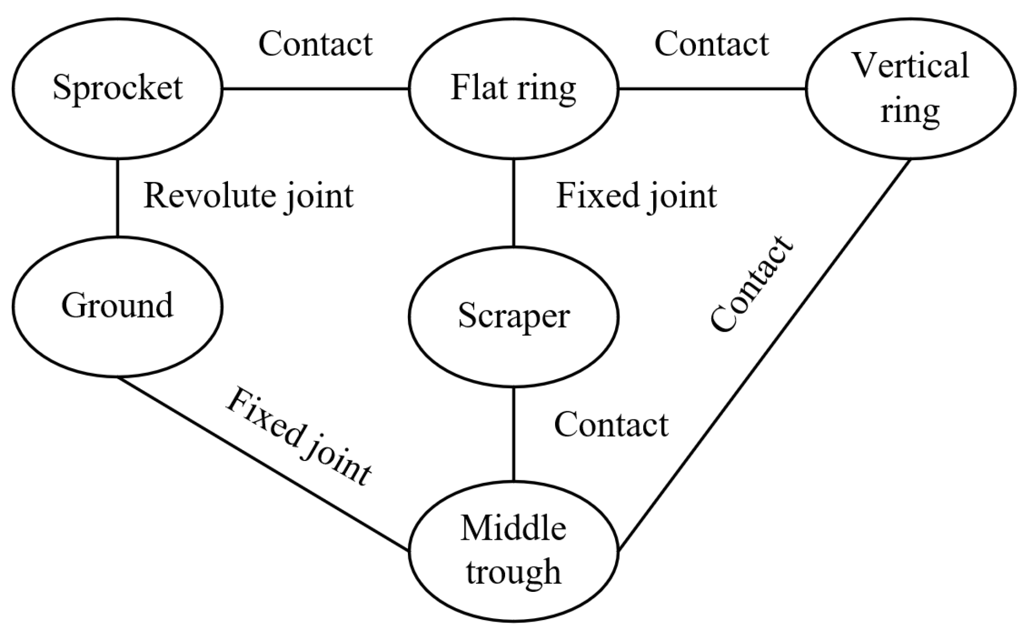
2.1. Modeling Process

During the operation of a scraper conveyor, the chain drive system circulates due to the meshing of the driving sprocket and chainring. This circular operation enables the scraper to transport coal, gangue, and other materials. The drive system is classified as a typical multibody dynamics system. In this paper, the SGZ1000/3 × 1000 scraper conveyor used in a fully mechanized mining face of a coal mine is taken as the prototype, and its specific technical parameters are shown in Table 1. The chain drive system of the scraper conveyor was modeled and assembled in three dimensions using SolidWorks software (2020), based on the two-dimensional drawings of key parts provided by the equipment manufacturer, and the model was imported into the dynamics simulation software ADAMS through the interface conversion function. Finally, the chain drive system model of the scraper conveyor was established, as shown in Figure 1.
To enhance simulation efficiency, the model is simplified as follows: (1) Neglect the head and tail frames of the scraper conveyor, which have little influence on the dynamic characteristics of the chain drive system. (2) Set the length of the chute as 4.6 m and simplify it into the form of a plate. (3) Focus on the sprocket, chain ring, and scraper of the scraper conveyor to carry out more detailed three-dimensional modeling. The simplified chain drive system model is a closed continuum, the upper chain is the loaded side, and the lower chain is the unloaded side, which contains a total of 144 chains, 2 sprockets, 8 scrapers, and 2 troughs.

2.2. Setting and Calculation of the Simulation Parameters

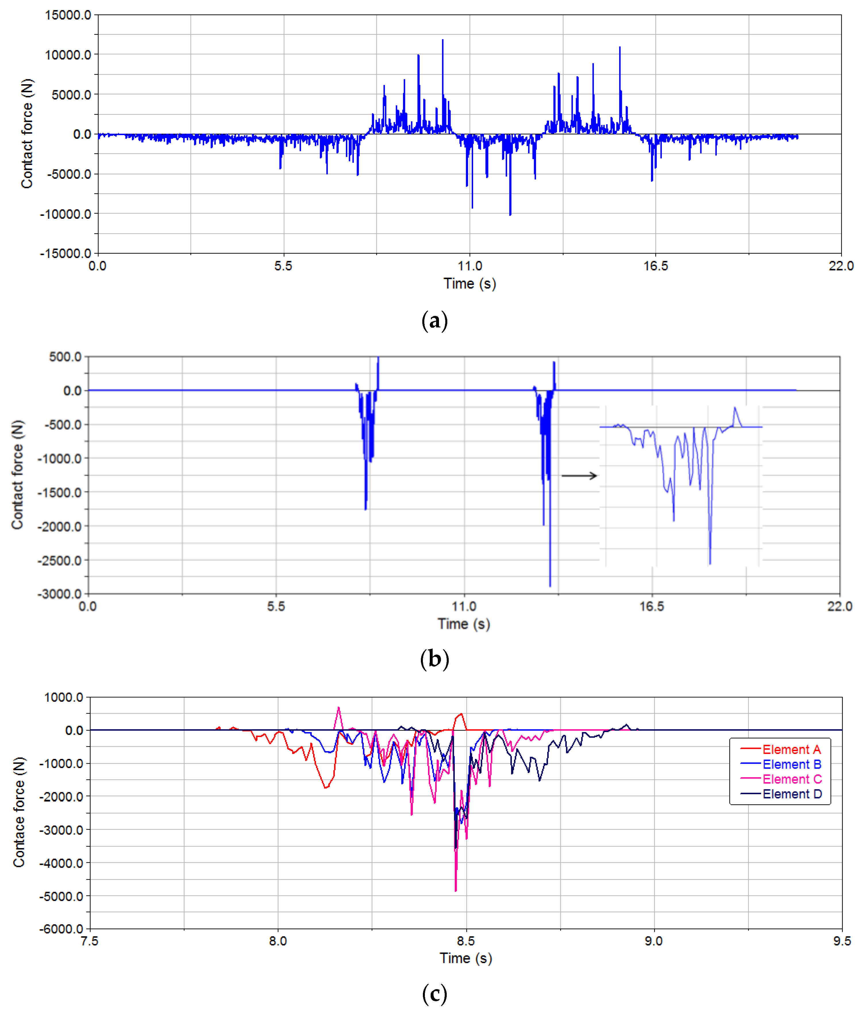
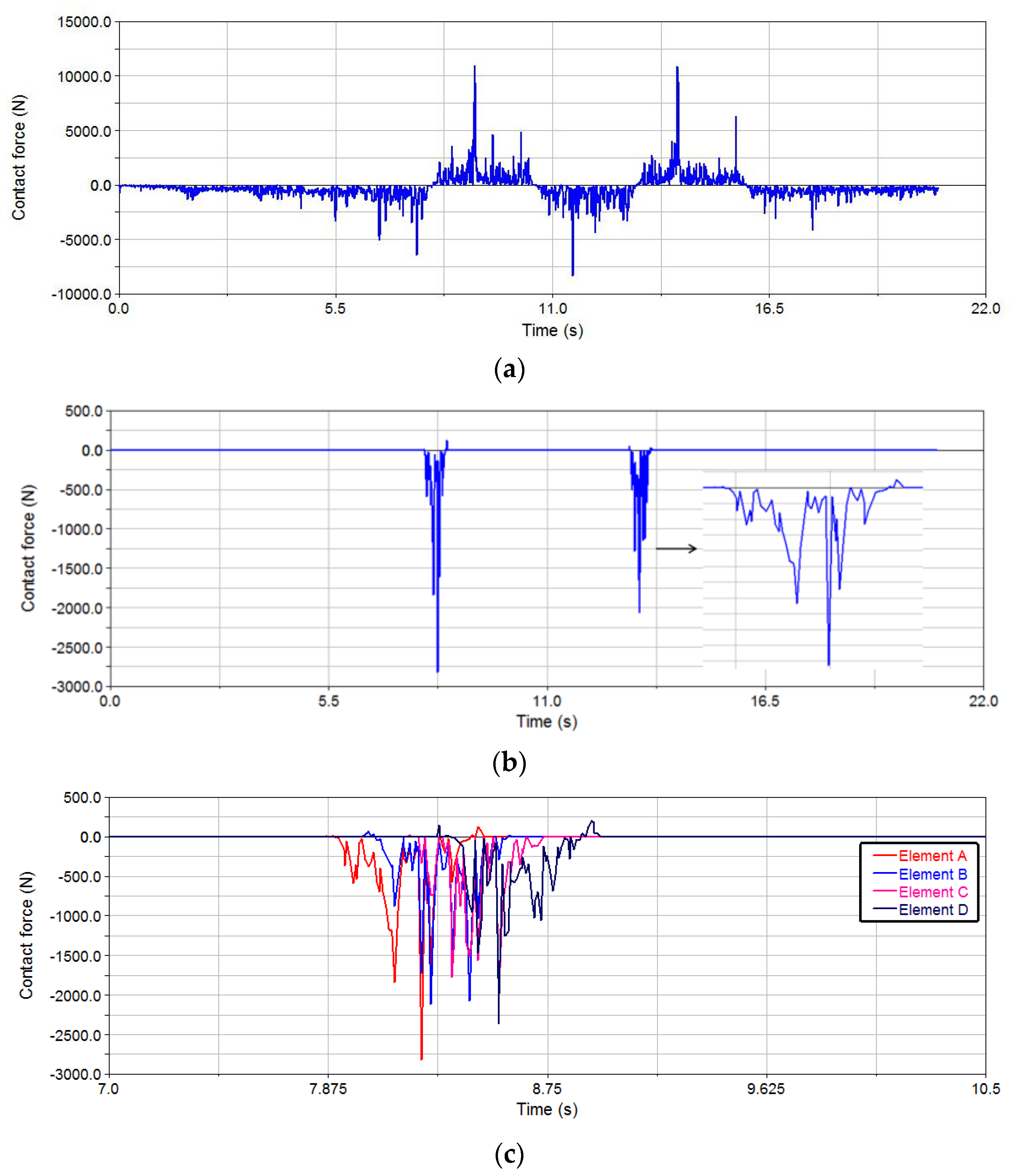
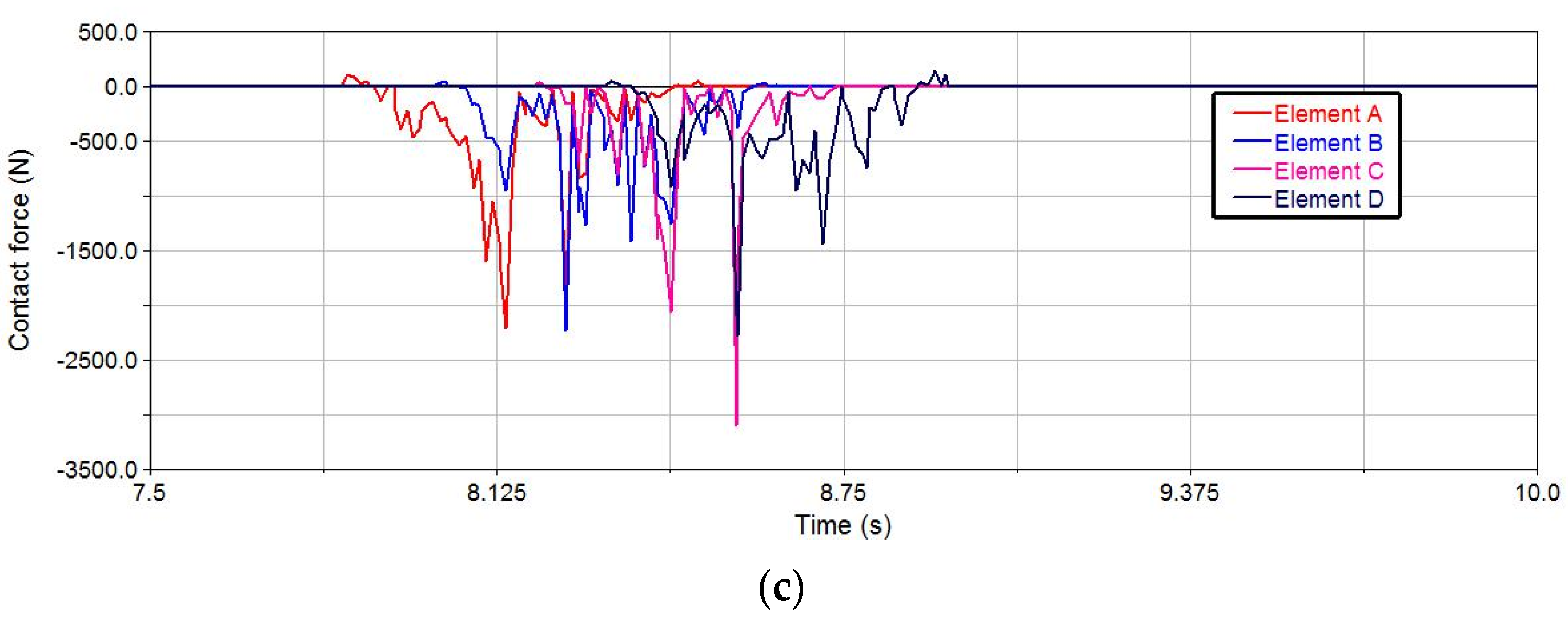
2.2.1. Calculation of Contact Force

The value of the contact force Fimp between the rigid bodies in contact can be solved through the impact function as follows:
F i m p = { 0 x x 0 k ( x 0 x ) e c d x d t s t e p ( x , x 0 δ , 1 , x 0 , 0 ) x < x 0
where k is the contact stiffness coefficient, x and x0 are the initial distance between the two contact bodies and the actual distance in the collision process, respectively, e is the contact collision index, c is the damping coefficient, δ is the maximum contact penetration depth, and step (·) is the step function.
The contact force generated by the collision of two contactors is composed of an elastic component and damping component. The contact stiffness k can be solved using the Hertz theory as follows:
{ k = 4 3 R 1 / 2 E 1 R = 1 R 1 + 1 R 2 1 E = ( 1     μ 1 2 ) E 1 + ( 1     μ 2 2 ) E 2
where R1 and R2 are the radii of curvature of the two contact bodies at the contact position, μ1 and μ2 are Poisson’s ratios of two contacts, and E1 and E2 are the elastic moduli of two contact materials.
The theoretical value of the damping coefficient c can be obtained as follows:
c = 3 k ( 1 ε e 2 ) 4 V δ n
where εe is the collision recovery coefficient of the contact, V is the relative velocity between the contact bodies, and n is the nonlinear coefficient of the contact force.
During the collision process, the movement of the contacting body causes a shift in the position of the contact point, resulting in a change in the curvature radius of the contact point. Consequently, the contact stiffness coefficient and damping coefficient also undergo continuous changes. However, in ADAMS software, the contact stiffness coefficient remains constant. After conducting theoretical calculations and multiple simulations and debugging, the contact stiffness k = 2.0 × 10⁵ N/mm, the damping coefficient c = 1000 N·s/mm, and the maximum contact penetration depth δ = 0.01 mm are finally selected.

2.2.2. Restriction Setting

To guarantee the precision of the simulation outcomes, it is imperative to thoroughly analyze the force interactions and motion properties among the system’s components, and then set up appropriate motion restrictions and load conditions. When the chain drive system is in operation, the main forces acting on it are the meshing force between the drive sprocket and the ring chain, the tension between the flat ring and the vertical ring, and the friction between the scraper chain and the trough. Figure 2 illustrates the restriction that exists between various components of the transmission system.

2.2.3. Calculation of Resistance

The running process of a scraper conveyor encounters several forms of resistance, including friction between coal and the middle trough, friction between the scraper chain and the middle trough, bending resistance caused by the s chainring around the head and tail sprockets, running resistance in the bending section of the middle trough, and the component force of coal and chain weight during inclined transportation. Usually, the resistance of the scraper conveyor during steady-state operations is subdivided into three components: the loaded, unloaded, and curved sections for computation. The resistance during the operation of a scraper conveyor is usually divided into three parts for calculation: the loaded side, unloaded side, and curved section.
The running resistance Fz of the scraper conveyor on the loaded side can be calculated as follows:
F z = ρ 1 L g ( μ 1 cos β ± sin β ) + ρ 2 L g ( μ 2 cos β ± sin β )
The running resistance Fk of the scraper conveyor on the unloaded side can be calculated as follows:
F k = ρ 2 L g ( μ 2 cos β sin β )
where ρ1 and ρ2 are, respectively, the mass of coal and the scraper chain per unit length, L is the length of scraper conveyor, μ1 and μ2 are, respectively, the resistance coefficients on the loaded and unloaded sides of the scraper conveyor, g is the acceleration of gravity, and β is the inclination angle of the scraper conveyor.
The calculation of bending running resistance and additional resistance is relatively complex and is usually calculated as 10% of the sum of the running resistance on the loaded and unloaded sides. The total running resistance F0 of the scraper conveyor can be calculated as follows:
F 0 = k 1 k 2 ( F z + F k )
where k1 and k2 are, respectively, the bending resistance and additional resistance coefficient of scraper conveyor.

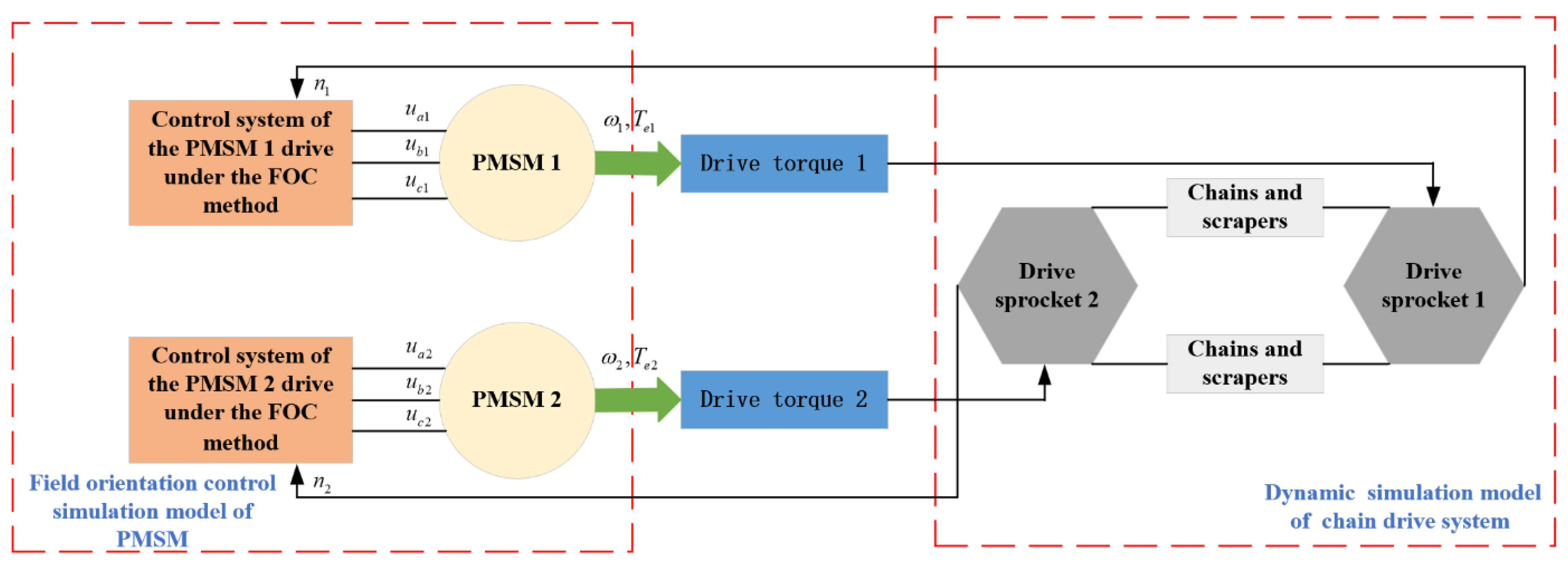
3. Design of PMSM-Driven System for Scraper Conveyor

The scraper conveyor’s permanent magnet drive system typically consists of a flameproof PMSM and a frequency converter. The system can be regulated by adjusting the voltage frequency. In the variable frequency speed regulation system of the PMSM, field-oriented control and direct torque control are the most widely used and technologically mature control strategies in modern engineering practice [28,29]. Vector control is essentially a kind of tracking and decoupling control mode. By coordinate transformation, the three-phase rotating AC is approximately converted into a d-axis and q-axis two-phase direct current to realize the decoupling of a multivariable system of permanent magnet motors. Then the excitation component generated by the d-axis and the electromagnetic torque component generated by the q-axis are controlled separately, so as to realize the efficient regulation of the permanent magnet motor. Since the permanent magnet drive system of the scraper conveyor involved in the subject has high requirements for low-speed performance, the field-oriented control strategy exciting current id = 0 control method is adopted, which has the characteristics of simple control, good torque performance, and a wide speed regulation range. Figure 3 displays the simulation block diagram of the control system for the PMSM.

3.1. Mathematical Model of the PMSM

The transformation of coordinates for the PMSM is essential in vector control. The notion of coordinate transformation allows the conversion of the stator current into torque current and excitation current. The equation for the voltage of the stator in the d–q rotating coordinate system of the PMSM can be described as follows:
{ u d = R s i d + d ϕ d d t ω r ϕ q u q = R s i q + d ϕ q d t ω r ϕ d
where ud and uq are the components of stator voltage on the d- and q-axes, id and iq are the components of stator current on the d- and q-axes, φd and φq are the components of stator flux on the d- and q-axes, Rs is the stator resistance, and ωr is the rotor electrical speed.
The flux equation of PMSM in the d–q rotating coordinate system is shown as follows:
{ ϕ d = L d i d + φ f ϕ q = L q i q
where φf is the permanent magnet flux linkage, and Ld and Lq are the components of the inductances on the d- and q-axes.
The stator current equation of the PMSM in the d–q rotating coordinate system is expressed as follows:
{ d i d d t = 1 L d ( u d R s i d + L q i q ω r ) d i q d t = 1 L q ( u q R s i q + L d i d ω r ω r ϕ f )
The electromagnetic torque equation of the PMSM in the d–q rotating coordinate system is expressed as follows:
T e = 3 2 n p i q [ φ f + ( L d L q ) i d ]
where Te is the electromagnetic torque and np is the pole number of the PMSM.
The mechanical motion equation of the PMSM in the d–q rotating coordinate system is expressed as follows:
T e T L = J d ω m d t + B ω m
where TL is the load torque, J is the moment of inertia, ωm is the rotor mechanical speed, and B is the viscosity coefficient.

3.2. Design of Sliding Mode Speed Controller

The drive system of the scraper conveyor is a complicated control object characterized by nonlinearity, robust coupling, and several variables. Adopting the traditional linear control method of proportional integral (PI) can suppress internal disturbances in closed-loop control. Nevertheless, the PI speed controller’s performance may be affected, and the control system may deviate from the desired target due to external disturbances that lead to fluctuations in the motor speed response. Sliding mode control is a nonlinear control technique that does not depend on precise model accuracy and exhibits robustness against external disturbances [30,31]. Therefore, this study utilizes the sliding mode speed controller in the control system of the PMSM.
The state variables of the PMSM are defined as follows:
{ x 1 = ω r e f ω m x 2 = x 1 · = ω m ·
where ωref is the reference speed of the PMSM.
Substituting (9) and (11) into (12), the state variables of the PMSM can be described as follows:
{ x 1 · = ω m · = p n J ( 1.5 p n φ f i q T L ) x 2 · = ω m · · = 1.5 p n 2 J φ f i q ·
The sliding surface s can be defined as follows:
s = c x 1 + x 2 , c > 0
The reaching law can be designed according to the exponential reaching law, which is described as follows:
s · = c x 1 · + x 2 · = c x 2 + x 2 = ε s g n ( s ) q s
The reference current of q axis is shown as follows:
i q = 2 J 3 p n φ f 0 t [ c x 2 + ε s g n ( s ) + q s ] d τ
A simulation model of the PMSM for a scraper conveyor was created using MATLAB/Simulink. The model was based on a sliding mode speed controller and the PMSM vector control strategy, using the parameters provided by the PMSM manufacturer (refer to Table 2). The model is shown in Figure 4.

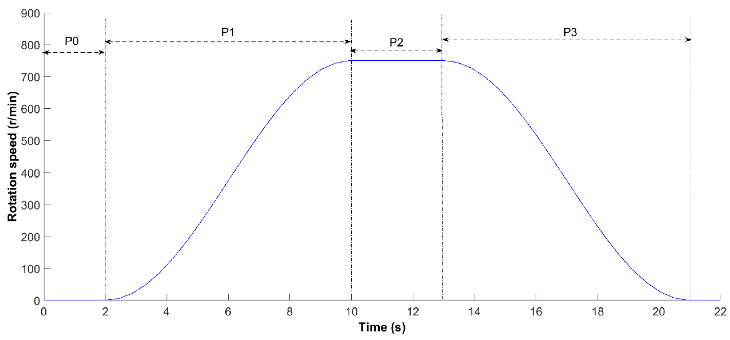
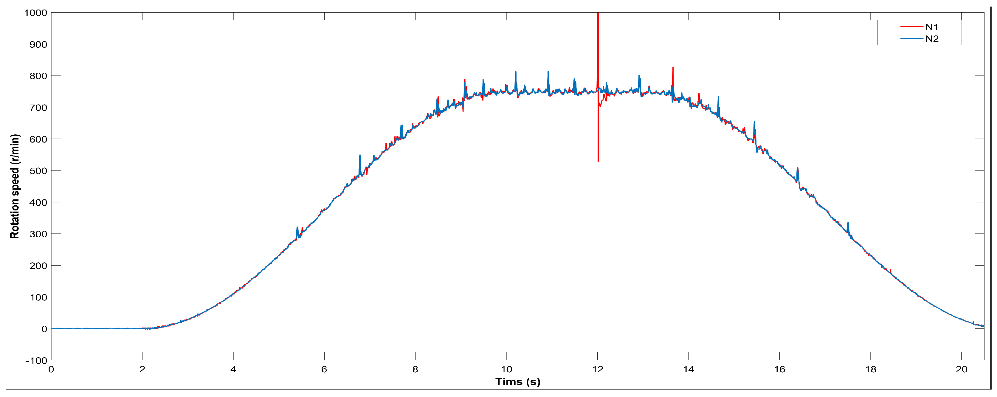
4. Simulation and Analysis under Typical Working Conditions

This research establishes an electromechanical joint simulation model of the permanent magnet-driven scraper conveyor based on the coupling relationship between the chain drive system of the scraper conveyor and the drive system of the PMSM, as shown in Figure 5. The control system of the PMSM in Simulink was used to drive the dynamic model of the chain drive system in ADAMS. The combined simulation model facilitates the transfer of torque output from the two motors to the scraper conveyor head and tail sprocket, respectively, in order to achieve torque transmission. Simultaneously, the speed data from the sprocket of the scraper conveyor are fed into the control system of the PMSM to guarantee the synchronization of the system’s speed. The entire system is controlled by utilizing the speed and torque information transmitted between the two subsystems.
Figure 6 shows the preset speed curve of the PMSM. The process is categorized into four stages, whereby P0 represents the tight chain stage of the chain drive system. P1 represents the starting stage, where the head and tail sprockets accelerate according to the preset S-type starting curve, and the chain speed reaches the rated chain speed of about 1.5 m/s in about 10 s. P2 represents the rated operation phase, during which the scraper chain maintains a uniform chain speed of 1.5 m/s. P3 is the deceleration–shutdown stage. The complete running curve comprises activities such as chain tightening, starting, rated operation, and braking stops, which can simulate various working conditions of the scraper conveyor.

4.1. No-Load Condition

Figure 7 shows the changes of the speed curve of the head motor N1 and the tail motor N2 under no-load conditions. The speeds of both motors can reach the preset target speed of 750 n/min, realizing the whole process of the scraper conveyor from start-up to rated operation and then braking. The figure demonstrates that as the speed increases, the polygon effect resulting from the interaction between the ring chain and sprocket becomes increasingly apparent. Additionally, the speed of the motor at the head and tail produces periodic fluctuations. Overall, under no-load conditions, the upper and lower chains have a similar load, resulting in a similar change in speed for the head and tail motors, with a small speed difference.
Figure 8 shows the simulation curve of the scraper conveyor under no-load conditions. Figure 8a shows the horizontal contact force curve between a group of flat rings and vertical rings (contact 273) in the scraper chain. The initial position of the set of ring chains is near the tail sprocket on the loaded side, and the ring chains begin to engage with the head sprocket when they run at 7.8 s and start to run on the unloaded side after they are disengaged at 8.5 s. The direction of the contact force is changed by the change in the running trajectory. During the whole operation of the chain drive system, the direction of the contact force between the ring chains has undergone four changes, and the peak value of the contact force in the acceleration stage (11,827 N) is significantly higher than those in the early start-up stage (5247 N) and late deceleration stage (5915 N). Figure 8b shows the change curve of the contact force during engagement between the flat ring and the sprocket of the machine head in this group of ring chains. The durations of the two engagement processes are 0.7 s and 0.8 s, respectively, and the maximum values of the contact force are 1763 N and 2897 N, respectively. In the whole engagement process of the ring chain and the sprocket of the machine head, there are four flat rings in the engagement zone at the same time in the engagement state with the sprocket, respectively denoted as elements A, B, C, and D. Figure 8c shows the changing trend of the contact force in the engagement curve. The process of engagement between the ring chain and sprocket can be categorized into three stages: initial engagement, full engagement, and disengagement. The contact force change law of different ring chains is basically the same during the engagement process, and the engagement contact force curve presents a state of high on both sides and low in the middle, which is manifested in that the contact force increases rapidly after entering the engagement state. With the continuous meshing process, the flat ring and sprocket gradually enter the stable contact state of complete meshing, and the contact force at this stage decreases obviously, and the contact force increases again before meshing disengagement.

4.2. Half-Load Condition

To account for the impact of the mining process, the load on the scraper conveyor typically falls between no load and full load. To simulate the conveyor’s performance under half-load conditions, the operating load is set at 50% of the rated load, and the settings of the running curve and motor speed are consistent with the no-load condition.
Figure 9 shows the speed curves of the head motor N1 and tail motor N2 under half-load conditions. The two motors can still realize the whole process, from starting to rated operation, and then braking according to the preset operating curves. Similar to the operation under no-load conditions, the speed curves of the head and tail motors fluctuate periodically due to the polygon effect. As a result of the varying loads on the upper and lower chains, the speed fluctuation of the head motor is slightly more pronounced than that of the tail motor. However, the overall trend of speed change remains consistent, and the disparity in speed between the two motors is minor.
Figure 10 shows the simulation curve of the scraper conveyor under the half-load condition. Figure 10a shows the change curve of the horizontal contact force of the same group of flat rings and vertical rings (contact 273) under half-load conditions. The change curve of the contact force under the half-load condition has similar fluctuations as that under the no-load condition, and the time when the peak contact force appears is consistent with that under the no-load condition. Due to the different load, the maximum contact force (6399 N) of the ring chain in the acceleration stage with the load side running is higher than that in the no-load condition (5247 N). Figure 10b shows the contact force curve of the flat ring and head sprocket engaged twice, and the maximum contact forces of the two engaging contact forces are, respectively, 2824 N and 2057 N. Figure 10c shows the change curve of the contact force between the four flat rings and the sprocket of the head in the engaging area at the same time. It can be more clearly seen from the figure that the contact force between the four groups of ring chains and sprocket in the engaging area has two obvious peaks, and the contact force curve of the meshing contact force as a whole presents the characteristics of high on both sides and low in the middle.

4.3. Rated Load Condition

Figure 11 shows the speed curves of the head motor N1 and tail motor N2 under rated load conditions. The overshoot of the speed of the head motor is obviously higher than that of the tail motor. According to the analysis of the motor speed curve in Figure 8a under the half-load condition, it is shown that the engagement of the load-side ring chain with the head sprocket is likely to cause a more significant impact due to the disparity in loads. This impact will have a greater effect on the speed of the head motor.
The simulation curve of the scraper conveyor under the rated load condition is shown in Figure 12. Figure 12a shows the change curve of the contact force between the flat ring and the vertical ring under rated load conditions. The maximum value of the contact force (16,075 N) appears in the acceleration stage of the load-side operation, which is significantly higher than those under no-load and half-load conditions. The polygon effect causes the contact force between the ring chains to exhibit irregular periodic variations under all three working conditions. The contact force experiences more intense fluctuations during the late acceleration stage and early deceleration stage compared to other stages of operation. Figure 12b shows the contact force curve during the engagement between the flat ring and the head sprocket under rated load conditions. The maximum values of the two engagement contact forces are 2208 N and 2189 N, respectively. Figure 12c shows the change curve of the contact force of four flat rings and sprockets engaged at the same time. The contact force curve in the figures closely aligns with the change trend observed under both no-load and half-load conditions, indicating a similar engagement process.

5. Conclusions

This study developed a combined simulation model of the PMSM drive system and chain drive system of the scraper conveyor for mining, using the mathematical model of the PMSM and dynamic model of the chain drive system. A numerical simulation was utilized to determine the motor speed, contact force between the chainring, and the change curve of the contact force between the sprocket and the ring chain in three typical working conditions. An analysis was conducted on the dynamic characteristics of the chain drive system of the mine scraper conveyor under the control of a permanent magnet motor drive system. Based on the results of this study, the following conclusions can be drawn:
(1) Under the influence of the polygon effect, the contact force between the ring chains in the chain drive system changes periodically under different working conditions, and the ring chains at the same position show similar force characteristics. Due to the different loads on the upper and lower chains, the horizontal contact force of the ring chain with the carrier side will increase significantly with the increase in load.
(2) In the process of engagement between the ring chain and the sprocket, there are four groups of flat rings in the engagement zone, which are in different engagement stages with the driving sprocket. The contact force gradually increases at the beginning stage of engagement, decreases significantly at the full engagement stage, and increases again at the disengagement stage, so the engagement contact force curve presents a state of high on both sides and low in the middle.
In conclusion, this paper provides a new idea for the study of the electromechanical coupling analysis of a scraper conveyor. The MATLAB/Simulink–ADAMS joint simulation model can offer methodological support and theoretical guidance for optimizing the control method of the permanent magnet drive motor. Simultaneously, the simulation results hold particular reference significance in investigating the dynamic characteristics of the chain drive system in the PMSM-driven scraper conveyor. Nevertheless, the operation of the scraper conveyor under actual working conditions is intricate. Due to constraints imposed by experimental and hardware conditions, the research conducted in this paper requires further enhancement. It is necessary to optimize the method and precision of model construction, as well as conduct a comparative analysis and research on the dynamic characteristics of the scraper conveyor under various drive motor and transmission system structures.

Author Contributions

Conceptualization, X.Z.; methodology, M.R.; software, M.R., H.W. and L.J.; writing—original draft, M.R.; writing—review and editing, X.Z. All authors have read and agreed to the published version of the manuscript.

Funding

This work is supported by the National Natural Science Foundation of China (grant No. 52121003).

Data Availability Statement

Data are contained within the article.

Conflicts of Interest

The authors declare no conflict of interest.

Correction Statement

This article has been republished with a minor correction to the existing affiliation information. This change does not affect the scientific content of the article.

References

  1. Jiang, S.; Huang, S.; Zeng, Q.; Chen, S.; Lv, J.; Zhang, Y.; Qu, W. Dynamic Characteristics of the Chain Drive System under Multiple Working Conditions. Machines 2023, 11, 819. [Google Scholar] [CrossRef]
  2. Wang, D.; Zhang, J.; Zhu, Z.; Gang, S.; Xiang, L. Crack initiation characteristics of ring chain of heavy-duty scraper conveyor under time-varying loads. Adv. Mech. Eng. 2019, 11, 2072157124. [Google Scholar] [CrossRef]
  3. Jiang, S.B.; Zeng, Q.L.; Wang, G.; Gao, K.D.; Wang, Q.Y.; Hidenori, K. Contact Analysis of Chain Drive in Scraper Conveyor Based on Dynamic Meshing Properties. Int. J. Simul. Model. 2018, 17, 81–91. [Google Scholar] [CrossRef] [PubMed]
  4. Wang, H.; Zhang, Q.; Xie, F. Dynamic tension test and intelligent coordinated control system of a heavy scraper conveyor. IET Sci. Meas. Technol. 2017, 11, 871–877. [Google Scholar] [CrossRef]
  5. Zhao, S.; Wang, P.; Li, S. Study on the Fault Diagnosis Method of Scraper Conveyor Gear under Time-Varying Load Condition. Appl. Sci. 2020, 10, 5053. [Google Scholar] [CrossRef]
  6. Jiang, S.; Lv, R.; Wan, L.; Mao, Q.; Zeng, Q.; Gao, K.; Yang, Y. Dynamic Characteristics of the Chain Drive System of Scraper Conveyor Based on the Speed Difference. IEEE Access 2020, 8, 168650–168658. [Google Scholar] [CrossRef]
  7. Hieu, L.D.; Temkin, I.O.; Van Tung, L. The application of the fuzzy controller for tension system control of the scraper conveyor in the mines. IOP Conf. Series. Mater. Sci. Eng. 2021, 1159, 12018. [Google Scholar] [CrossRef]
  8. Li, L.; Cui, H.; Lian, Z.; Wang, Q. Modeling and Optimization of Soft Start-Up for Hydroviscous Drive Applied to Scraper Conveyor. Math. Probl. Eng. 2019, 2019, 131364. [Google Scholar] [CrossRef]
  9. Lu, E.; Li, W.; Yang, X.; Xu, S. Simulation study on speed control of permanent magnet direct-driven system for mining scraper conveyor. Int. J. Eng. Syst. Model. Simul. 2018, 10, 1–11. [Google Scholar] [CrossRef]
  10. Ren, W.J.; Wang, L.; Mao, Q.H.; Jiang, S.B.; Huang, S. Coupling Properties of Chain Drive System under Various and Eccentric Loads. Int. J. Simul. Model. 2020, 19, 643–654. [Google Scholar] [CrossRef]
  11. Zhang, X.; Li, W.; Zhu, Z.; Ren, W.; Jiang, F. Tension monitoring for the ring chain transmission system using an observer-based tension distribution estimation method. Adv. Mech. Eng. 2017, 9, 2071941813. [Google Scholar] [CrossRef]
  12. Jiang, S.; Huang, S.; Mao, Q.; Zeng, Q.; Gao, K.; Lv, J. Dynamic Properties of Chain Drive in a Scraper Conveyor under Various Working Conditions. Machines 2022, 10, 579. [Google Scholar] [CrossRef]
  13. Lu, J.; Yang, R.; Mao, J.; Xie, C. Longitudinal torsional vibrations of the chain drive system of mine scraper conveyor. Sci. Rep. 2023, 13, 9174. [Google Scholar] [CrossRef] [PubMed]
  14. Dai, K.; Zhu, Z.; Shen, G.; Li, X.; Tang, Y.; Wang, W. Modeling and Adaptive Tension Control of Chain Transmission System With Variable Stiffness and Random Load. IEEE Trans. Ind. Electron. 2022, 69, 8335–8345. [Google Scholar] [CrossRef]
  15. Jiang, S.B.; Huang, S.; Zeng, Q.L.; Wang, C.L.; Gao, K.D.; Zhang, Y.Q. Dynamic Properties of Chain Drive System Considering Multiple Impact Factors. Int. J. Simul. Model. 2022, 21, 284–295. [Google Scholar] [CrossRef]
  16. Yuan, P.; He, B.; Zhang, L. Dynamic modelling of an armoured face conveyor considering the curved chains. Eng. Comput. 2023, 40, 1147–1174. [Google Scholar] [CrossRef]
  17. Rahman, S.U.; Xia, C. Rotor Speed and Position Estimation Analysis of Interior PMSM Machines in Low and Medium-High Speed Regions Adopting an Improved Flux Observer for Electric Vehicle Applications. Machines 2023, 11, 574. [Google Scholar] [CrossRef]
  18. Liang, J.; Jia, H.; Chen, M.; Kong, L.; Hu, H.; Guo, L. Modeling and Disturbance Compensation Sliding Mode Control for Solar Array Drive Assembly System. Aerospace 2023, 10, 501. [Google Scholar] [CrossRef]
  19. Qu, P.; Sun, Z.; Li, Q.; Zhang, J.; Liu, P.; Zhou, D. Dynamic Simulation of Multiple Launch Rocket System Marching Fire Based on the Fuzzy Adaptive Sliding Mode Control. Machines 2023, 11, 427. [Google Scholar] [CrossRef]
  20. Zhao, X.; Kou, B.; Huang, C.; Zhang, L. Optimization Design and Performance Analysis of a Reverse-Salient Permanent Magnet Synchronous Motor. Machines 2022, 10, 204. [Google Scholar] [CrossRef]
  21. Sheng, L.; Li, W.; Wang, Y.; Fan, M.; Yang, X. Sensorless Control of a Shearer Short-Range Cutting Interior Permanent Magnet Synchronous Motor Based on a New Sliding Mode Observer. IEEE Access 2017, 5, 18439–18450. [Google Scholar] [CrossRef]
  22. Lu, E.; Li, W.; Yang, X.; Xu, S. Composite Sliding Mode Control of a Permanent Magnet Direct-Driven System For a Mining Scraper Conveyor. IEEE Access 2017, 5, 22399–22408. [Google Scholar] [CrossRef]
  23. Ju, J.; Li, W.; Wang, Y.; Fan, M.; Yang, X. Dynamics and nonlinear feedback control for torsional vibration bifurcation in main transmission system of scraper conveyor direct-driven by high-power PMSM. Nonlinear Dyn. 2018, 93, 307–321. [Google Scholar] [CrossRef]
  24. Sheng, L.; Li, W.; Jiang, S.; Chen, J.; Liu, A. Nonlinear torsional vibration analysis of motor rotor system in shearer semi-direct drive cutting unit under electromagnetic and load excitation. Nonlinear Dyn. 2019, 96, 1677–1691. [Google Scholar] [CrossRef]
  25. Chen, J.; Li, W.; Sheng, L.; Jiang, S.; Li, M. Study on reliability of shearer permanent magnet semi-direct drive gear transmission system. Int. J. Fatigue 2020, 132, 105387. [Google Scholar] [CrossRef]
  26. Li, D.; Wang, S. Characteristics of new permanent magnetic eddy current drive system of the scraper conveyor. J. Eng. 2021, 2021, 552–558. [Google Scholar] [CrossRef]
  27. Jiang, S.; Ren, W.; Mao, Q.; Zeng, Q.; Yu, P.; Gao, K.; Wang, L. Dynamic Analysis of the Scraper Conveyor under Abnormal Operating Conditions Based on the Vibration and Speed Characteristics. Shock. Vib. 2021, 2021, 8887744. [Google Scholar] [CrossRef]
  28. Xu, W.; Junejo, A.K.; Liu, Y.; Hussien, M.G.; Zhu, J. An Efficient Antidisturbance Sliding-Mode Speed Control Method for PMSM Drive Systems. IEEE Trans. Ind. Electron. 2021, 36, 6879–6891. [Google Scholar] [CrossRef]
  29. Shinohara, A.; Inoue, Y.; Morimoto, S.; Sanada, M. Maximum Torque Per Ampere Control in Stator Flux Linkage Synchronous Frame for DTC-Based PMSM Drives Without Using q-Axis Inductance. IEEE Trans. Ind. Appl. 2017, 53, 3663–3671. [Google Scholar] [CrossRef]
  30. Wang, Y.; Feng, Y.; Zhang, X.; Liang, J. A New Reaching Law for Antidisturbance Sliding-Mode Control of PMSM Speed Regulation System. IEEE Trans. Power Electron. 2020, 35, 4117–4126. [Google Scholar] [CrossRef]
  31. Junejo, A.K.; Xu, W.; Mu, C.; Ismail, M.M.; Liu, Y. Adaptive Speed Control of PMSM Drive System Based a New Sliding-Mode Reaching Law. IEEE Trans. Power Electron. 2020, 35, 12110–12121. [Google Scholar] [CrossRef]
Figure 1. Simplified model of scraper conveyor chain drive system.
Processes 12 00165 g001
Figure 2. Restriction of the system.
Processes 12 00165 g002
Figure 3. Block diagram of the PMSM control system. (ωr* is the target speed, iq* is the q-axis current component regulated by the PI controller, and id* is the given d-axis current component.)
Processes 12 00165 g003
Figure 4. Simulation model of the PMSM control system.
Processes 12 00165 g004
Figure 5. Block diagram of electromechanical joint simulation model of PMSM-driven scraper conveyor.
Processes 12 00165 g005
Figure 6. Preset speed curve of the PMSM.
Processes 12 00165 g006
Figure 7. Simulation curve of motor speed under no-load condition (N1: speed of head motor, N2: speed of tail motor).
Processes 12 00165 g007
Figure 8. Simulation curve under no-load condition. (a) Horizontal contact force between the flat ring and the vertical ring; (b) contact force between the flat ring and the sprocket; (c) contact force between the four flat rings and the head sprocket in the engagement zone.
Processes 12 00165 g008
Figure 9. Simulation curve of motor speed under half-load condition (N1: speed of head motor, N2: speed of tail motor).
Processes 12 00165 g009
Figure 10. Simulation curve under half-load condition. (a) Horizontal contact force between the flat ring and the vertical ring; (b) contact force between the flat ring and the sprocket; (c) contact force between the four flat rings and the head sprocket in the engagement zone.
Processes 12 00165 g010
Figure 11. Simulation curve of motor speed under rated load condition (N1: speed of head motor, N2: speed of tail motor).
Processes 12 00165 g011
Figure 12. Simulation curve under rated load condition. (a) Horizontal contact force between the flat ring and the vertical ring; (b) contact force between the flat ring and the sprocket; (c) contact force between the four flat rings and the head sprocket in the engagement zone.
Processes 12 00165 g012aProcesses 12 00165 g012b
Table 1. Technical parameters of the SGZ1000/3 × 1000 scraper conveyor.
ParameterValueUnit
Transmission capacity3500t/h
Length330m
Chain velocity0–1.89m/s
Horizontal inclination of fully
mechanized working face
≤±9°
Middle trough size
(length × width × height)
1750 × 1000 × 350mm
Form of chainringDouble center chain-
Chain specification48 × 152mm
Breaking force≥2900kN
Space of scraper912mm
Source from DingMax Mining Machinery.
Table 2. Simulation parameters of the PMSM.
ParameterValueUnit
Pole pairs number4-
Stator resistance0.0238Ω
Flux linkage0.8151Wb
Rotational inertia4.165kg·m2
Viscosity coefficient0.005N·m·s
D-axis inductance0.0143H
Q-axis inductance0.042H
Rated speed750r/min
Source from Beijing BeTech Co., Ltd (Beijing, China).
Disclaimer/Publisher’s Note: The statements, opinions and data contained in all publications are solely those of the individual author(s) and contributor(s) and not of MDPI and/or the editor(s). MDPI and/or the editor(s) disclaim responsibility for any injury to people or property resulting from any ideas, methods, instructions or products referred to in the content.

