Abstract
The stability of salt cavern storage during prolonged operation is a crucial indicator of its safety. This study focuses on an operational underground gas storage facility, conducting comparative numerical simulations for the storage of natural gas and hydrogen. We investigated the evolution of stability for natural gas and hydrogen storage under long-term storage conditions. The main conclusions are as follows: (1) A new equation for stress equilibrium and constitutive relations are derived. (2) At the same storage pressure, the effective stress at the same position in the interlayer is greater for hydrogen storage compared to natural gas storage, signifying a higher level of danger. (3) At the same storage pressure, the displacement at the cavity top for hydrogen storage is greater than that for natural gas storage. The displacement difference between the two is greatest at 9 MPa, amounting to 0.026 m. (4) Due to hydrogen’s lower dynamic viscosity and higher permeability, the depth and extent of the plastic zones within the interlayers are greater compared to natural gas. When the storage pressure is 15 MPa, the depth of the plastic zone within the interlayer can be up to 2.1 m greater than when storing natural gas, occurring in the third interlayer from the top. These research findings may serve as a valuable reference for determining the operational parameters of on-site salt cavern hydrogen storage facilities.
1. Introduction
Underground hydrogen storage facilities primarily encompass salt caverns [1], aquifers [2], depleted oil and gas reservoirs [3], and lined rock caverns [4]. Presently, the successful application observed globally is in salt cavern hydrogen storage [5]. Developed nations, led by the United States, are diligently advancing scientific and technological research on hydrogen storage technology. Similarly, the United Kingdom, Germany, and Canada have also established plans for salt cavern hydrogen storage [6,7,8]. In addition to storing methane and hydrogen, salt caverns can also store CO2 to reduce the greenhouse effect [9]. Although China possesses underground salt cavern gas storage facilities, the distinct physicochemical properties of hydrogen compared to methane mean that the technology and experience used for natural gas storage cannot be directly applied to hydrogen storage in salt caverns [10]. The utilization of salt caverns for hydrogen storage must take into account the unique properties of hydrogen and the particularities of our salt formations, such as their thin layers and numerous interlayers.
The stability of a storage facility during long-term operations is a crucial indicator for assessing its safety. Scholars both domestically and internationally have conducted research and evaluations on the safety of salt cavern storage through indoor rock characteristic tests and numerical simulations. Yang et al. [11] developed a Cosserat constitutive model that reflects the interlayer bending effects, which is based on the composite medium characteristics of layered salt rock. Zhu et al. [12] applied the aforementioned model to the analysis of stability in salt cavern storage. Guo et al. [13] integrated the Cosserat model into numerical simulation software COMSOL Multiphysics 5.6. and applied it to the stability analysis of gas storage reservoirs, thereby establishing a fundamental framework for transitioning the model from theoretical to practical engineering applications. Shi et al. [14] investigated the mechanism of collapse in multi-layer salt rock gas storage reservoirs and proposed a predictive method for layer collapse instability. Zhang et al. [15] examined the stability of salt cavern reservoirs with varying interlayer contents through numerical simulations. Zhang et al. [16] employed a fractional derivative creep damage constitutive model to study the long-term stability and safety of gas reservoirs under various constant internal gas pressures and extraction rates. Li et al. [17] developed a coupled model for salt rock dissolution and interlayer failure, introducing the salt dissolution rate equation and the brine concentration flow field equation for dynamic cavern development, and analyzed the stability of the reservoir. Liu et al. [18] established a corresponding mechanical model based on the physical and mechanical parameters of the Jintan salt mine and investigated the impact of long-term gas injection and production on the stability of salt caverns. Firme et al. [19] developed a computational model for calculating the volumetric loss of gas reservoirs based on field monitoring results from the French Etrez and Tersanne storage sites, incorporating both laboratory experiments and theoretical analysis. Wang et al. [20,21] employed numerical simulation software COMSOL Multiphysics 6.0 to analyze the stability of salt cavern reservoirs under various conditions such as different pillar spacing, cavern morphology, and cyclic internal pressure. Chen et al. [22] developed a theoretical model for the leakage analysis of multi-layered salt cavern gas storage reservoirs, specifically targeting lacustrine sedimentary salt rocks rich in argillaceous interlayers in our country, and examined the factors influencing gas leakage and reservoir stability.
The aforementioned studies have predominantly focused on the stability of natural gas storage in salt caverns, with a notable deficiency in research concerning hydrogen storage. When utilizing salt caverns for hydrogen storage, the unique characteristics of hydrogen must be taken into account. Firstly, in comparison to natural gas, hydrogen exhibits a lower density, higher diffusion coefficient, and greater permeability. Secondly, during the cyclical storage and release process, hydrogen experiences more significant compression heat effects and generates greater thermal stress. Lastly, hydrogen is primarily employed for peak shaving, which necessitates frequent cycles of storage and release. The stability of the salt cavern under such high-frequency cyclic storage and release conditions remains uncertain. This paper derives an evaluation equation for the stability of hydrogen storage in salt caverns and investigates the differences between storing natural gas and hydrogen under long-term storage conditions. The findings provide a theoretical foundation for hydrogen storage in salt caverns.
2. Damage Constitutive Model of Salt Cavern Gas Storage Due to Thermal Stress
During the operation of gas storage facilities, thermal stress in the formation primarily arises from several factors. Due to the presence of a geothermal gradient, the extent of thermal expansion and contraction varies from the surface to greater depths. The formation will experience thermal stress due to constraints from mutual deformation. In the case of layered salt rocks, the differing thermal expansion coefficients of impurities such as clay and gypsum create differential thermal expansion, resulting in thermal stress. Throughout the cyclic injection and extraction of gas, temperature variations within the cavity lead to temperature differences between the inner and outer layers of the salt rock, generating periodically varying thermal stress.
2.1. Model Assumptions
- (1)
- Both the salt layers and interlayers are isotropic homogeneous media.
- (2)
- The temperature and density of hydrogen are solely dependent on time.
- (3)
- Hydrogen adheres to the ideal gas law, and its flow conforms to Darcy’s law.
- (4)
- Before the hydrogen cycle of storage and release, the salt cavern contains hydrogen gas at a certain initial temperature and pressure.
2.2. Model Derivation
Taking into account the combined effects of linear elastic deformation, thermal expansion, and the nonlinear creep of the surrounding rock, derive the equations for stress equilibrium and constitutive relations.
The equilibrium equation of stress is:
where u is the displacement tensor; ρ is the material density, kg/m3; σ is the stress tensor; g is the acceleration due to gravity, m/s2; and t is the time, s.
The stress expression is given by
where σ0 is the initial stress tensor, D is the elasticity tensor, ε0 is the initial strain tensor, εth is the thermal strain, and εcr is the creep strain.
The strain expression is given by
Thermal strain is determined using the linear thermal expansion law:
where αT is the coefficient of thermal expansion, m/K, Tref is the reference temperature, which is the in situ formation temperature, K, and I is the identity matrix.
Creep strain is determined using the Norton material model:
where A is the creep rate coefficient, 1/s; σeff is the effective stress, MPa; σref is the reference stress, MPa; σd is the deviatoric stress tensor, Qa is the creep activation energy, K; and R is the gas constant.
Evaluate cavity stability during cyclic injection and production using both the Mohr–Coulomb (M-C) criterion and the Drucker–Prager (D-P) criterion. The damage instability criteria based on stress state and mechanical strength are as follows:
where c is the M-C cohesion, kPa; ϕ is the internal friction angle, °; k and α are the D-P strength parameters; and m is the Mohr–Coulomb parameter defined by the internal friction angle.
3. Numerical Simulation Computation
3.1. Engineering Background and Geometric Model
The numerical simulation software selected is COMSOL Multiphysics 6.2 (COMSOL AB, Stockholm, Sweden). Using the J106 salt cavern storage facility in Jintan as a model, and based on the on-site sonar measurement results, a simplified numerical model was established, as illustrated in Figure 1. Design four distinct numerical simulation experiments for long-term gas storage at various pressures (9 MPa, 11 MPa, 13 MPa, and 15 MPa) for hydrogen and natural gas, comparing the stability of the chamber during prolonged storage of the two gases.
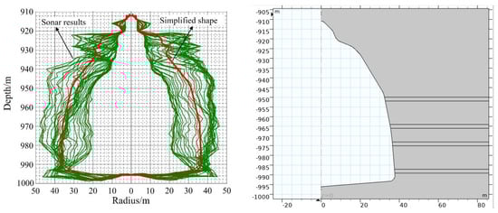
Figure 1.
Shape of the salt cavern J106 and the geometric model.
3.2. Parameter Configuration
The values of various input parameters in the simulation experiments are derived from field measurements and literature references. The detailed significance and values of these parameters are presented in Table 1 and Table 2.

Table 1.
Parameters for hydrogen and natural gas.
Table 2.
Permeability parameters of salt rock and mud.
3.3. Software Settings and Boundary Conditions
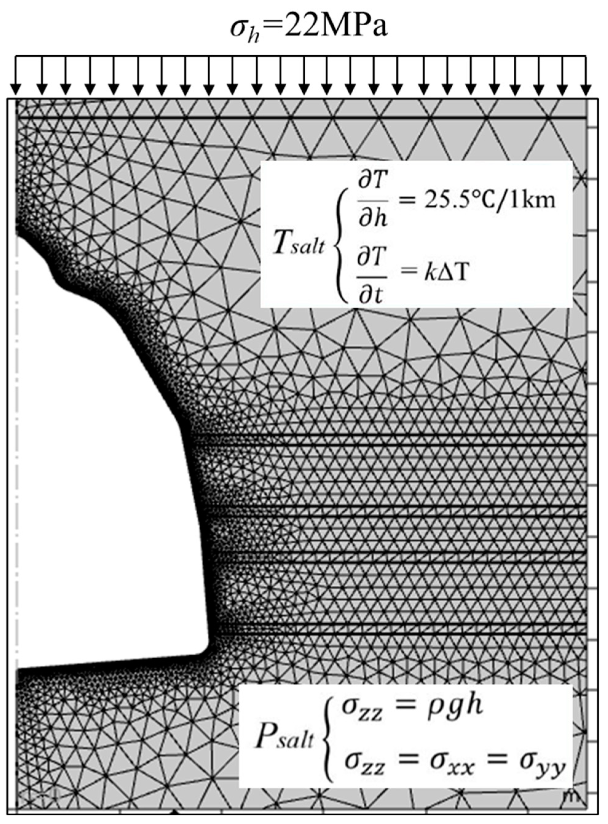
Figure 2 illustrates the grid partitioning. This geometric model employs a zonal mesh division approach. Refinements have been implemented in the interlayer, while an ultra-fine mesh has been applied around the cavity. It also shows the boundary and initial conditions of the model. The cavern wall is subjected to gas pressure and has a heat exchange with the gas. And the weight of the overlying formation at −900 m is simplified as the boundary load applied to the top of the model. The initial temperature is determined by the surface temperature (293.15 K) and the geothermal gradient (25.5 K/km). In this calculation, the step size is set to 10 days, with a convergence criterion of a relative tolerance of 1 × 10⁻⁴.

Figure 2.
Grid partitioning and boundary conditions of the numerical model.
3.4. Uncertainty Evaluation
In this study, in order to compare the uncertainty ranges, the method proposed in reference [23] was used. The proximity of the uncertainty ranges is assessed by measuring the maximum vertical difference. This analysis was also carried out using the Kolmogorov–Smirnov (KS) test.
4. Results and Discussion
4.1. Stability of Gas Storage in Salt Caverns under Constant Pressure
4.1.1. Effective Stress in Cavity
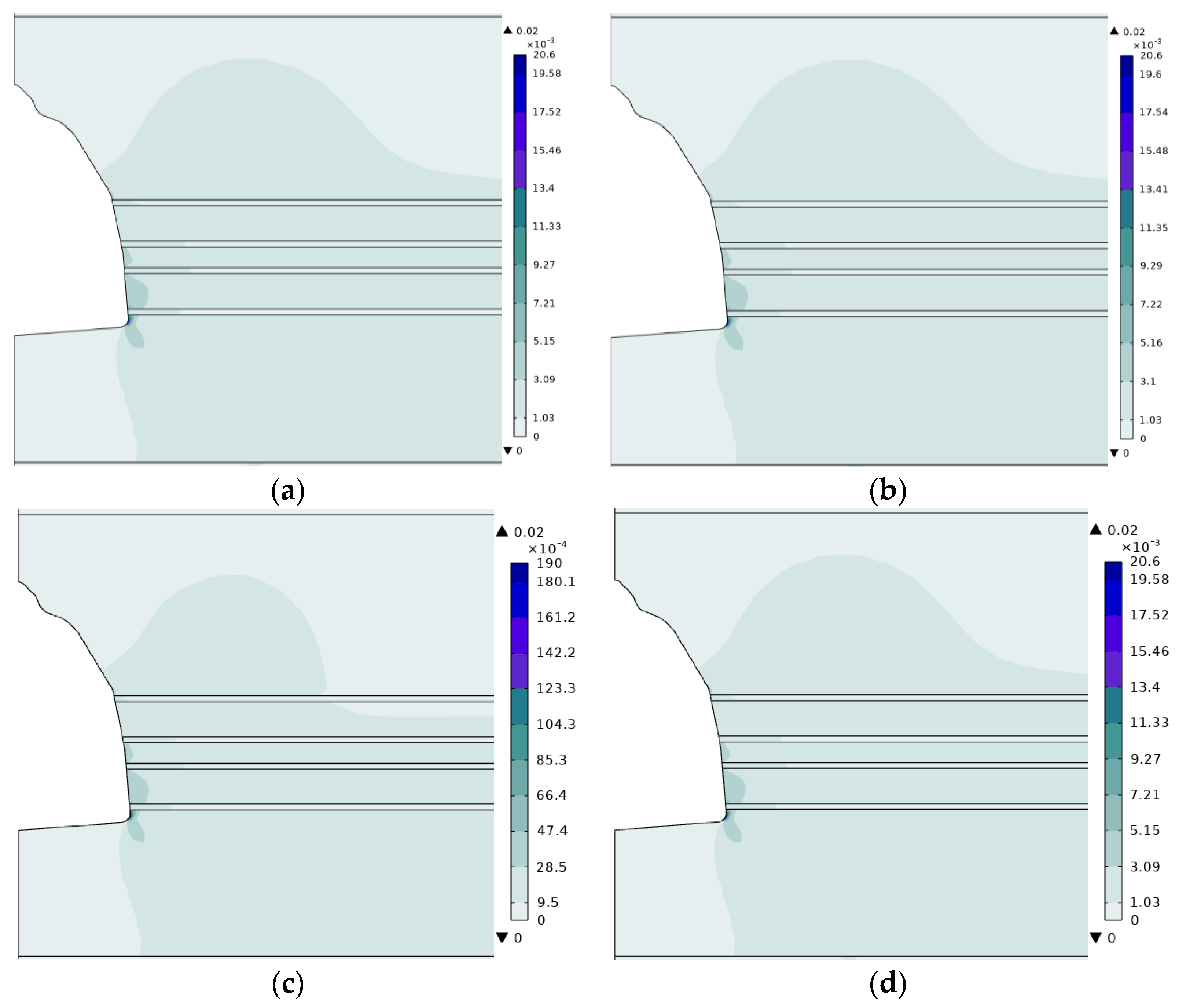
As depicted in Figure 3, the contour maps of effective stress in the cavity under different gas storage pressure conditions for salt cavern hydrogen and natural gas storage are shown. Under varying storage pressures, whether for hydrogen or natural gas, the maximum effective stress is consistently concentrated in the interlayer, indicating that this region is most susceptible to stress concentration and hence poses the greatest risk. At the same storage pressure, the effective stress at the same position in the interlayer is greater for hydrogen storage compared to natural gas storage, signifying a higher level of danger. This is due to the lower molecular weight and higher permeability coefficient of hydrogen, which facilitates its seepage into the interlayer more readily. Under fluid–solid coupling conditions, the gas seepage pressure effect is more pronounced, leading to a higher likelihood of stress concentration.
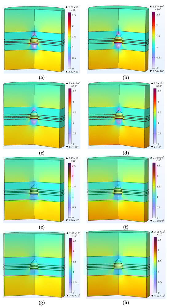
Figure 3.
Effective stress contour map of the cavity: (a) 9 MPa (natural gas); (b) 9 MPa (hydrogen); (c) 11 MPa (natural gas); (d) 11 MPa (hydrogen); (e) 13 MPa (natural gas); (f) 13 MPa (hydrogen); (g) 15 MPa (natural gas); (h) 15 MPa (hydrogen).
4.1.2. Cavity Displacement
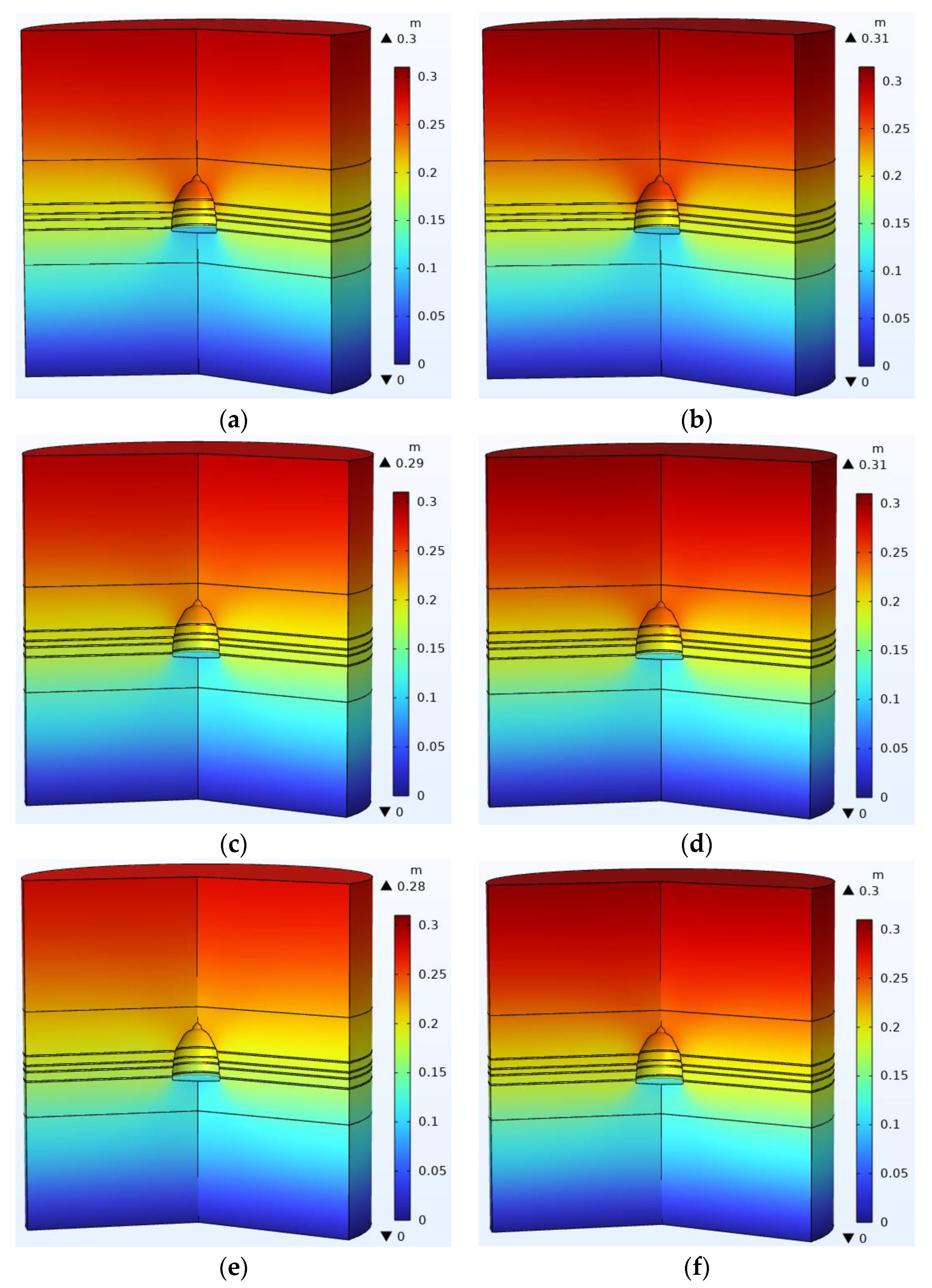
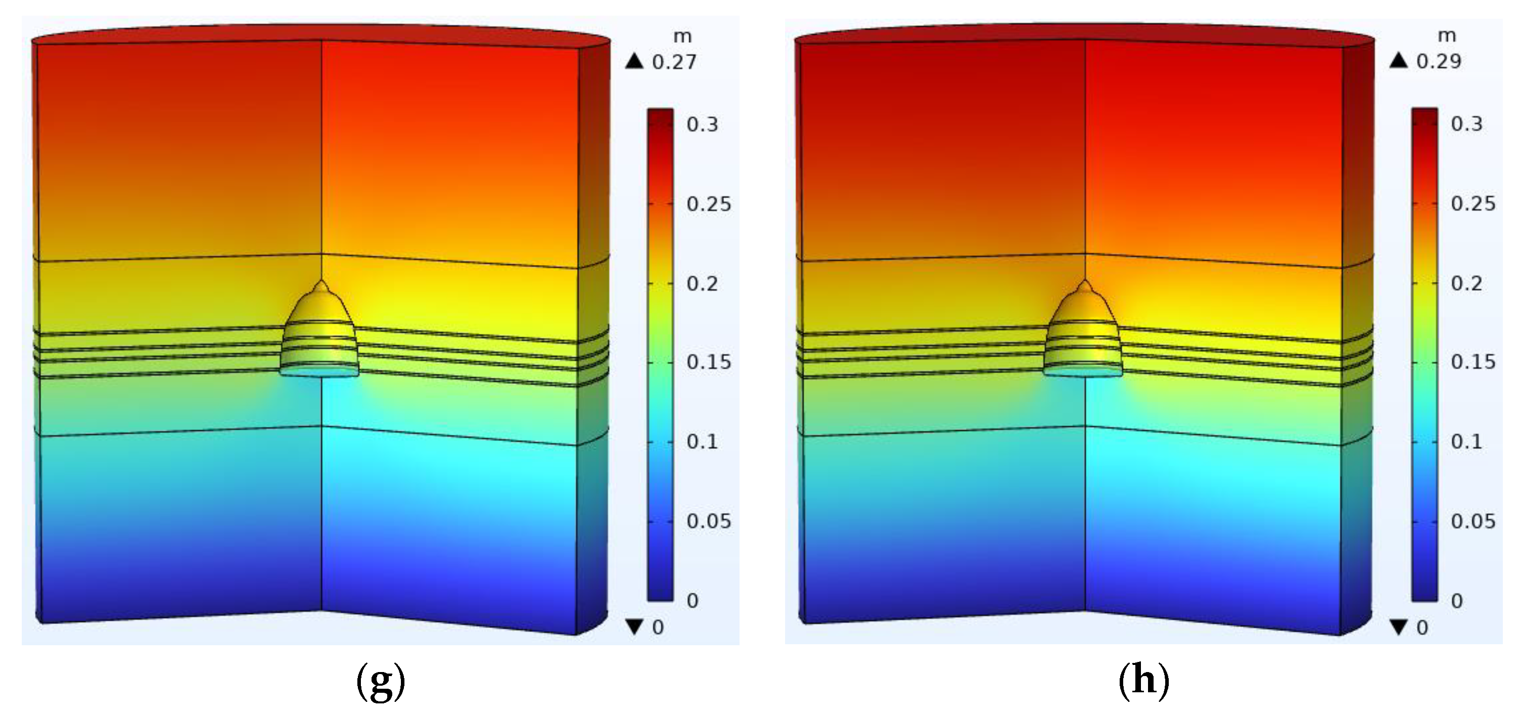
As depicted in Figure 4, the displacement contour maps of the cavern under different gas storage pressure conditions are illustrated for both hydrogen and natural gas storage. Under varying storage pressures, the maximum and minimum displacements of the cavern occur at the top and bottom, respectively. The maximum displacement at the top of the cavern is attributed to the combination of creep subsidence due to gravity and downward displacement caused by the release of support pressure from below. Conversely, the minimum displacement at the cavern’s base is due to the upward bulging of the floor resulting from the pressure relief above.

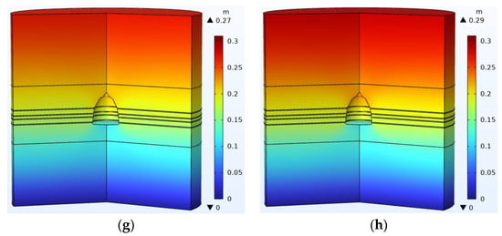
Figure 4.
Displacement contour map of the cavity: (a) 9 MPa (natural gas); (b) 9 MPa (hydrogen); (c) 11 MPa (natural gas); (d) 11 MPa (hydrogen); (e) 13 MPa (natural gas); (f) 13 MPa (hydrogen); (g) 15 MPa (natural gas); (h) 15 MPa (hydrogen).
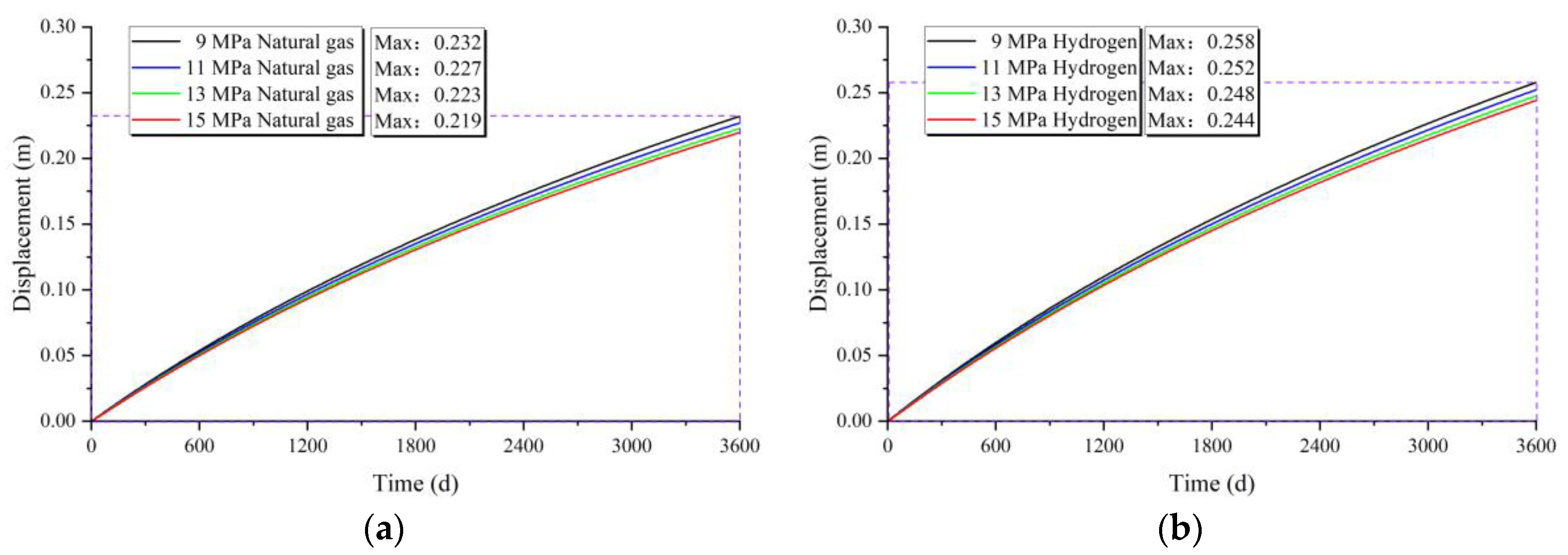
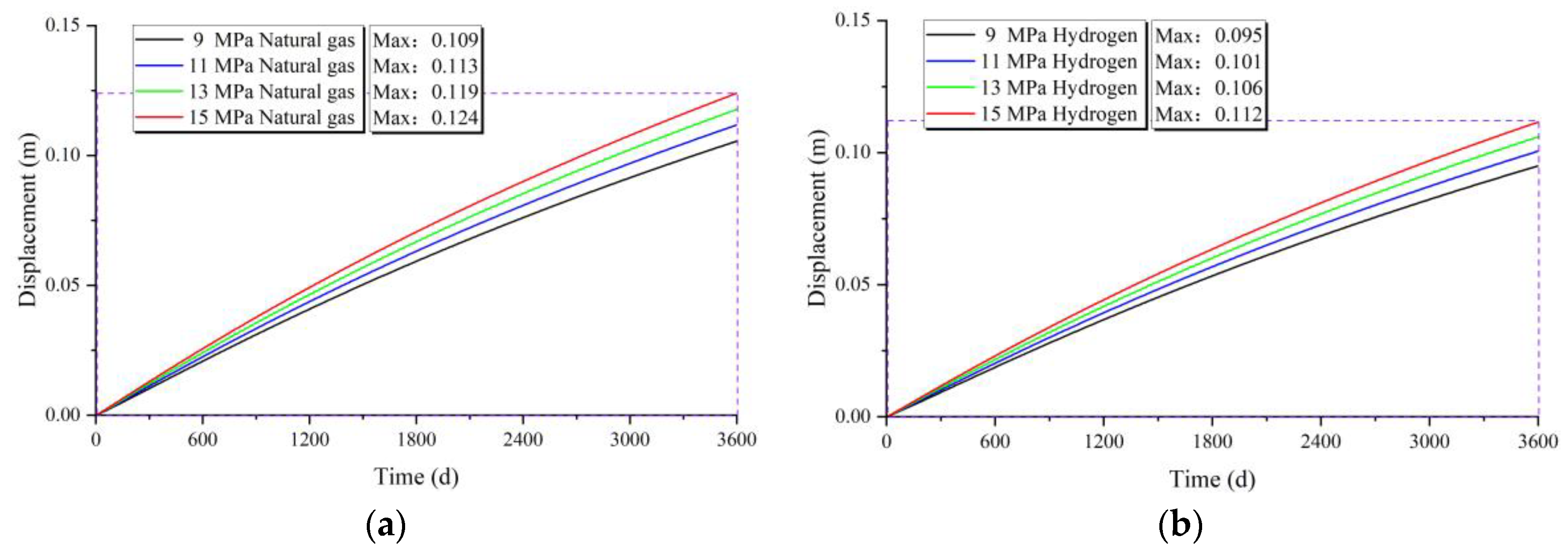
As illustrated in Figure 5, the displacement curve of the cavity top during hydrogen and natural gas storage in salt caverns is presented. With increasing storage pressure, the displacement at the cavity top gradually decreases. This indicates that higher storage pressures correspond to greater safety of the cavity. When storing hydrogen at 9 MPa, the maximum displacement of the cavity top is 0.263 m, which constitutes 0.33% of the cavity height, well below the 10% safety displacement threshold. At the same storage pressure, the displacement at the cavity top for hydrogen storage is greater than that for natural gas storage. The displacement difference between the two is greatest at 9 MPa, amounting to 0.026 m.
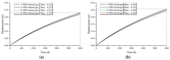
Figure 5.
Displacement curves of the cavity roof: (a) natural gas and (b) hydrogen.
As illustrated in Figure 6, the displacement curves of the cavity bottom for hydrogen and natural gas storage in salt caverns are depicted. With the increase in storage pressure, the displacement of the cavity bottom plate progressively increases. This is due to the fact that, at higher storage pressures, the upward displacement of the bottom plate is reduced, resulting in an increase in the absolute displacement of the bottom plate after subtracting the upward displacement from the downward creep displacement. At the same storage pressure, the displacement of the cavity bottom plate for hydrogen storage is lower than that for natural gas, following a trend opposite to that of the top. The maximum difference in displacement between the two occurs at 9 MPa, with a value of 0.014 m.
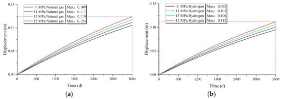
Figure 6.
Displacement curves of the cavity base: (a) natural gas and (b) hydrogen.
4.1.3. Constant Pressure Rheology
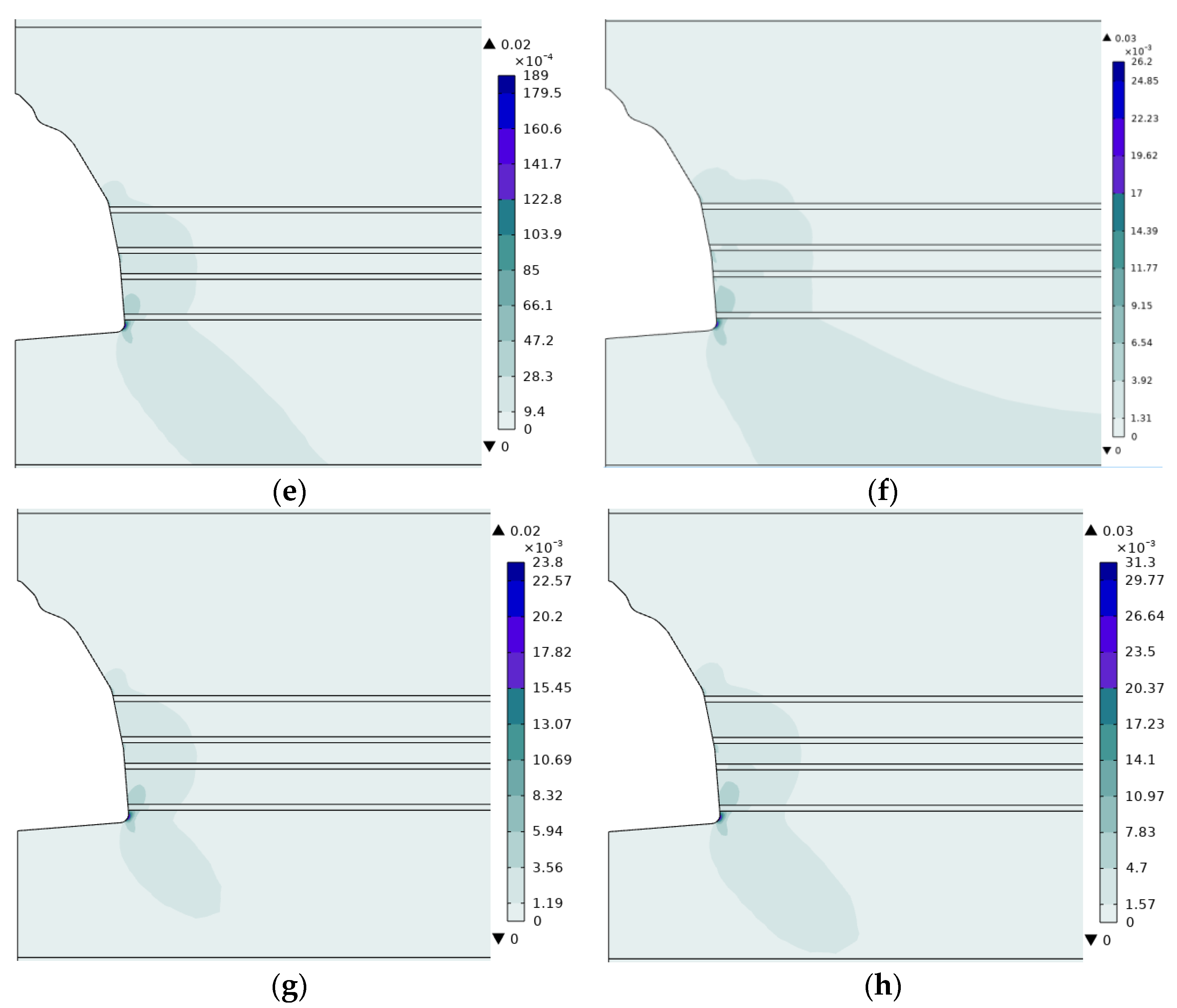
As the gas storage pressure increases, whether for hydrogen or natural gas, the magnitude and extent of the surrounding rock’s creep gradually decrease, indicating that a rise in storage pressure suppresses rock creep. Under varying storage pressure conditions, the equivalent creep strain magnitude and extent of the surrounding rock in hydrogen storage cavities are higher compared to those in natural gas storage. This is due to the greater permeability pressure and diffusion range of hydrogen compared to natural gas, resulting in a larger effective stress on the surrounding rock, thereby causing a greater creep strain and a more extensive creep range (Figure 7).
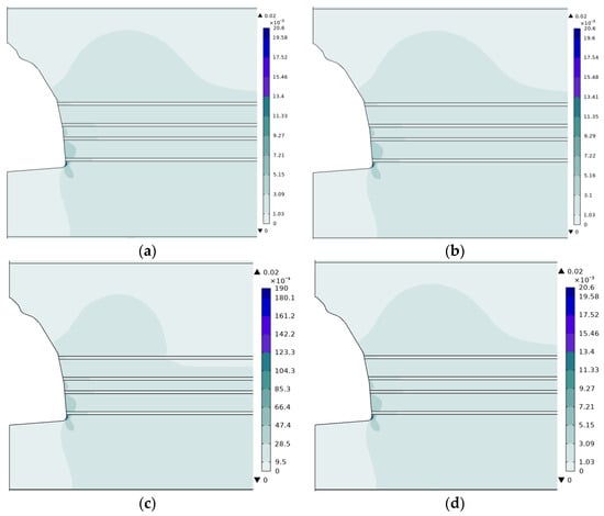

Figure 7.
Creep strain contour map of the surrounding rock: (a) 9 MPa (natural gas); (b) 9 MPa (hydrogen); (c) 11 MPa (natural gas); (d) 11 MPa (hydrogen); (e) 13 MPa (natural gas); (f) 13 MPa (hydrogen); (g) 15 MPa (natural gas); (h) 15 MPa (hydrogen).
4.1.4. Plastic Zone of the Surrounding Rock
As illustrated in Figure 8, the plastic zones of the surrounding rock in the salt cavern gas storage under different gas pressure conditions are depicted. With increasing gas pressure, the plastic zones at the top and bottom of the cavity progressively diminish. However, due to the presence of gas seepage within the interlayer, the area of the plastic zone within the interlayer progressively increases as the gas pressure rises. This indicates that while higher storage pressures can suppress the plastic zones at the top and bottom of the cavity, they exacerbate the plastic zone within the interlayer.
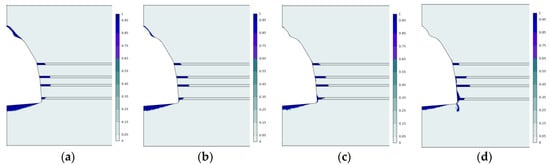
Figure 8.
The plastic zone of the surrounding rock in the salt cavern of natural gas storage: (a) 9 Mpa, (b) 11 Mpa, (c) 13 Mpa, and (d) 15 Mpa.
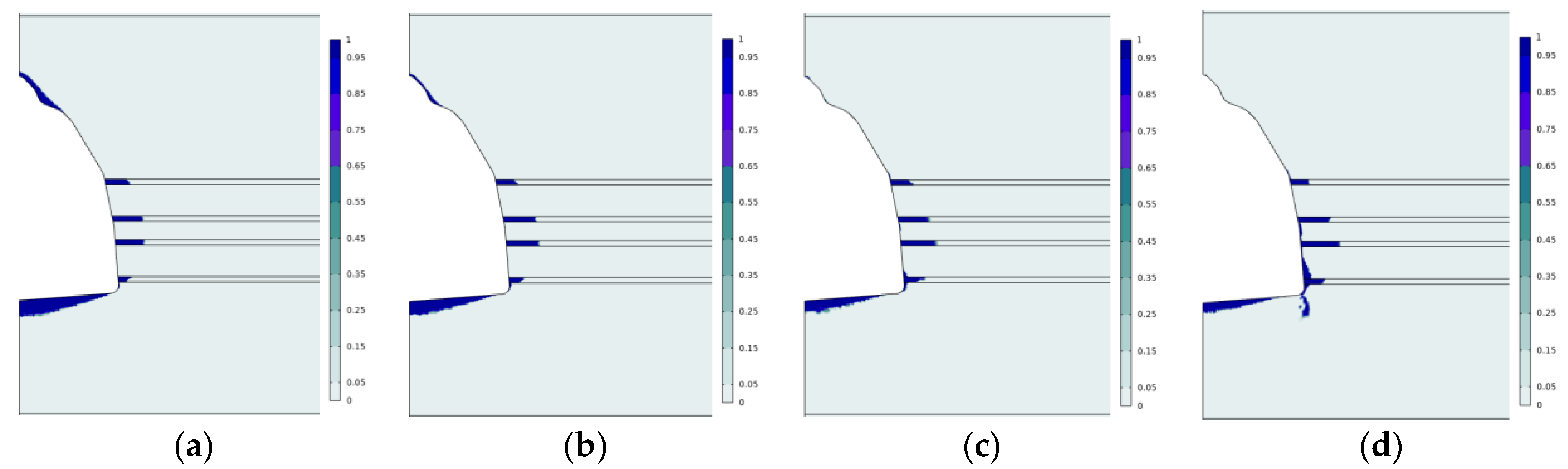
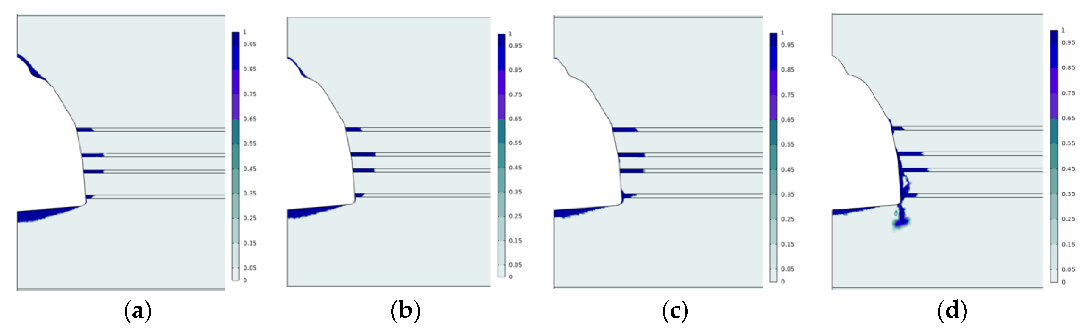
Figure 9 illustrates the plastic zones of the surrounding rock in a salt cavern hydrogen storage under various gas pressure conditions. For hydrogen, as the gas pressure increases, the plastic zones at the top and bottom of the cavity exhibit similar trends to those observed with natural gas. Due to hydrogen’s lower dynamic viscosity and higher permeability, the depth and extent of the plastic zones within the interlayers are greater compared to natural gas. Specifically, when the storage pressure is 15 MPa, the depth of the plastic zone within the interlayer can be up to 2.1 m greater than when storing natural gas, occurring in the third interlayer from the top. Furthermore, when storing hydrogen at 13 MPa, the area of the plastic zone in the cavity and interlayers is approximately equal to the corresponding plastic zone area when storing natural gas at 15 MPa.
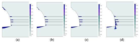
Figure 9.
The plastic zone of the surrounding rock in the salt cavern of hydrogen storage: (a) 9 Mpa, (b) 11 Mpa, (c) 13 Mpa, and (d) 15 Mpa.
5. Conclusions
- (1)
- By placing greater emphasis on the enhanced thermal effects during the hydrogen cyclic storage and release process, the equations for stress equilibrium and constitutive relations are derived.
- (2)
- At the same storage pressure, the effective stress at the same position in the interlayer is greater for hydrogen storage compared to natural gas storage, signifying a higher level of danger.
- (3)
- At the same storage pressure, the displacement at the cavity top for hydrogen storage is greater than that for natural gas storage. The displacement difference between the two is greatest at 9 MPa, amounting to 0.026 m.
- (4)
- Due to hydrogen’s lower dynamic viscosity and higher permeability, the depth and extent of the plastic zones within the interlayers are greater compared to natural gas.
In summary, when utilizing underground gas storage for hydrogen energy, it is imperative to reduce the storage pressure of hydrogen and continuously monitor the variations in pressure within the cavity.
Author Contributions
Conceptualization, Z.L.; methodology, Y.L. All authors have read and agreed to the published version of the manuscript.
Funding
This study was sponsored by the National Key Research and Development Program of China (2023YFB4005500), Basic Research Funding for the Central Universities of China (2024KYJD1010), the National Natural Science Foundation of China (52404103), and the Natural Science Foundation of Jiangsu Province (BK20241658).
Data Availability Statement
The raw data supporting the conclusions of this article will be made available by the authors upon request.
Conflicts of Interest
The authors declare no conflicts of interest.
References
- Zhu, S.; Shi, X.; Yang, C.; Li, Y.; Li, H.; Yang, K.; Liu, X. Hydrogen loss of salt cavern hydrogen storage. Renew. Energy 2023, 218, 119267. [Google Scholar] [CrossRef]
- Indro, A.P.; Okoroafor, E.R. Analytical equations to estimate hydrogen storage efficiency factor and storage capacity in saline aquifers. J. Energy Storage 2024, 92, 112228. [Google Scholar] [CrossRef]
- Sainz-Garcia, A.; Abarca, E.; Rubi, V.; Grandia, F. Assessment of feasible strategies for seasonal underground hydrogen storage in a saline aquifer. Int. J. Hydrogen Energy 2017, 42, 16657–16666. [Google Scholar] [CrossRef]
- Gajda, D.; Lutynski, M. Hydrogen Permeability of Epoxy Composites as Liners in Lined Rock Caverns-Experimental Study. Appl. Sci. 2021, 11, 3885. [Google Scholar] [CrossRef]
- Thiyagarajan, S.R.; Emadi, H.; Hussain, A.; Patange, P.; Watson, M. A comprehensive review of the mechanisms and efficiency of underground hydrogen storage. J. Energy Storage 2022, 51, 104490. [Google Scholar] [CrossRef]
- Tarkowski, R.; Uliasz-Misiak, B. Towards underground hydrogen storage: A review of barriers. Renew. Sustain. Energy Rev. 2022, 162, 112451. [Google Scholar] [CrossRef]
- Muhammed, N.S.; Haq, B.; Al Shehri, D.; Al-Ahmed, A.; Rahman, M.M.; Zaman, E. A review on underground hydrogen storage: Insight into geological sites, influencing factors and future outlook. Energy Rep. 2022, 8, 461–499. [Google Scholar] [CrossRef]
- Tarkowski, R. Underground hydrogen storage: Characteristics and prospects. Renew. Sustain. Energy Rev. 2019, 105, 86–94. [Google Scholar] [CrossRef]
- Li, Q.; Wang, Y.L.; Wang, Y.J.; San, J.; Li, Q.; Foster, G. Synthetic process on hydroxyl-containing polydimethylsiloxane as a thickener in CO2 fracturing and thickening performance test. Energy Sources Part A. Recovery Util. Environ. Eff. 2018, 40, 1137–1143. [Google Scholar] [CrossRef]
- Abuaisha, M.; Rouabhi, A.; Billiotte, J.; Hadj-Hassen, F. Non-isothermal two-phase hydrogen transport in rock salt during cycling in underground caverns. Int. J. Hydrogen Energy 2021, 46, 6632–6647. [Google Scholar] [CrossRef]
- Yang, C.; Jing, W.; Daemen, J.J.K.; Zhang, G.; Du, C. Analysis of major risks associated with hydrocarbon storage caverns in bedded salt rock. Reliab. Eng. Syst. Saf. 2013, 113, 94–111. [Google Scholar] [CrossRef]
- Zhu, S.; Shi, X.; Yang, C.; Bai, W.; Wei, X.; Yang, K.; Li, P.; Li, H.; Li, Y.; Wang, G. Site selection evaluation for salt cavern hydrogen storage in China. Renew. Energy 2024, 224, 120143. [Google Scholar] [CrossRef]
- Guo, Y.; Lan, X.; Cao, J.; Xu, B.; Xia, Y.; Yin, J.; Liu, Z. A comparative study of the reversible hydrogen storage behavior in several metal decorated graphyne. Int. J. Hydrogen Energy 2013, 38, 3987–3993. [Google Scholar] [CrossRef]
- Shi, X.; Liu, W.; Chen, J.; Yang, C.; Li, Y.; Ma, H.; Peng, H.; Wang, T.; Ma, X. Geological Feasibility of Underground Oil Storage in Jintan Salt Mine of China. Adv. Mater. Sci. Eng. 2017, 2017, 3159152. [Google Scholar] [CrossRef]
- Zhang, X.; Liu, W.; Jiang, D.; Qiao, W.; Liu, E.; Zhang, N.; Fan, J. Investigation on the influences of interlayer contents on stability and usability of energy storage caverns in bedded rock salt. Energy 2021, 231, 120968. [Google Scholar] [CrossRef]
- Zhang, N.; Yang, C.; Shi, X.; Wang, T.; Yin, H.; Daemen, J. Analysis of mechanical and permeability properties of mudstone interlayers around a strategic petroleum reserve cavern in bedded rock salt. Int. J. Rock Mech. Min. Sci. 2018, 112, 1–10. [Google Scholar] [CrossRef]
- Li, J.; Tang, Y.; Shi, X.; Xu, W.; Yang, C. Modeling the construction of energy storage salt caverns in bedded salt. Appl. Energy 2019, 255, 113866. [Google Scholar] [CrossRef]
- Liu, W.; Zhang, Z.; Chen, J.; Jiang, D.; Wu, F.; Fan, J.; Li, Y. Feasibility evaluation of large-scale underground hydrogen storage in bedded salt rocks of China: A case study in Jiangsu province. Energy 2020, 198, 117348. [Google Scholar] [CrossRef]
- Firme, P.A.L.P.; Quevedo, R.J.; Roehl, D.; Pereira, L.C.; Cazarin, C.L. Mechanical behavior of carbonate reservoirs with single karst cavities. Geomech. Energy Environ. 2021, 25, 100209. [Google Scholar] [CrossRef]
- Wang, T.; Yang, C.; Ma, H.; Daemen, J.; Wu, H. Safety evaluation of gas storage caverns located close to a tectonic fault. J. Nat. Gas Sci. Eng. 2015, 23, 281–293. [Google Scholar] [CrossRef]
- Wang, T.; Ding, Z.; He, T.; Xie, D.; Liao, Y.; Chen, J.; Zhu, K. Stability of the horizontal salt cavern used for different energy storage under varying geological conditions. J. Energy Storage 2024, 84, 110817. [Google Scholar] [CrossRef]
- Chen, S.; Zhang, Q.; Wang, G.; Zhu, L.; Li, Y. Investment strategy for underground gas storage facilities based on real option model considering gas market reform in China. Energy Econ. 2018, 70, 132–142. [Google Scholar] [CrossRef]
- Mahjour, S.K.; Badhan, J.H.; Faroughi, S.A. Uncertainty quantification in CO2 trapping mechanisms: A case study of PUNQ-S3 reservoir model using representative geological realizations and unsupervised machine learning. Energies 2024, 17, 1180. [Google Scholar] [CrossRef]


Disclaimer/Publisher’s Note: The statements, opinions and data contained in all publications are solely those of the individual author(s) and contributor(s) and not of MDPI and/or the editor(s). MDPI and/or the editor(s) disclaim responsibility for any injury to people or property resulting from any ideas, methods, instructions or products referred to in the content. |
© 2024 by the authors. Licensee MDPI, Basel, Switzerland. This article is an open access article distributed under the terms and conditions of the Creative Commons Attribution (CC BY) license (https://creativecommons.org/licenses/by/4.0/).