Article

Numerical Simulation and Experimental Study on Dynamic Characteristics of Gas Turbine Rotor System Subjected to Ship Hull Excitation

College of Power Engineering, Naval University of Engineering, Wuhan 430033, China
*
Authors to whom correspondence should be addressed.
Processes 2024, 12(10), 2091; https://doi.org/10.3390/pr12102091
Submission received: 9 September 2024 / Revised: 23 September 2024 / Accepted: 24 September 2024 / Published: 26 September 2024
(This article belongs to the Section Manufacturing Processes and Systems)

Abstract

:
To address the challenge of measuring the dynamic characteristic parameters of the gas turbine rotor system affected by hull excitation, a vibration transmission model integrating a ship model slice, test data, and a three-dimensional entity is proposed, based on the two-dimensional slice theory, scaled ship model, and finite element model of the turbine rotor system. The transient dynamic responses of the front and rear bearing points were calculated and analyzed. Vibration response tests with significant wave heights of 0.5 m, 1.25 m, 2.5 m, and 4 m were carried out in the towing tank of the ship model to obtain the dynamic characteristic parameters of the deck position. Techniques including wavelet denoising, Fast Fourier Transform (FFT), and signal resampling were employed to filter out and reconstruct high-frequency noise, overcoming the technical challenges of a high sampling frequency and a low computational efficiency. The experimental data and simulation results were compared and analyzed, validating the accuracy of the vibration transmission model of the turbine rotor system with data and entity integration. By comparing the vibration signal values in the X and Z directions at the front and rear bearing points after vibration transmission, it is evident that the effective values of the vibration signals at the front bearing point are 0.03% to 0.1% greater than those at the rear bearing point. This model provides a theoretical basis and reference for the design of the gas turbine rotor system.

1. Introduction

The rotor system, a core component of a gas turbine, is crucial to maintaining dynamic performance and service life for the operating performance and stability of the gas turbine. In a complex and changeable marine environment, ships will produce large-displacement low-frequency longitudinal and transverse swings. Since the turbine support system is fixed on the ship hull, the vibration generated by the longitudinal and transverse swings of the ship will be transmitted to the turbine support system through the hull and then to the rotor system. Although the vibration frequency generated by the longitudinal and transverse swings of the ship is much smaller than the speed of the turbine rotor system, these vibrations have a great impact on the dynamic characteristics of the turbine rotor system through the bearing oil film force, such as bearing burnout [1], operational instability [2], fatigue damage [3], and other issues, thereby affecting the stability and operational safety of the gas turbine. In order to improve the reliability level and environmental adaptability of the gas turbine rotor system in various marine environments and compensate for the influence of disturbance factors such as sea wind and waves which are ignored when studying the stability of the gas turbine rotor system, it is necessary to conduct in-depth research on the dynamic characteristics of the gas turbine rotor system of the ship in different marine environments.
Many scholars have conducted theoretical and experimental research on the dynamic characteristics of a marine gas turbine rotor system, yielding a series of findings. Ren, Y. et al. [4] established a gear-foundation coupling dynamic model considering flexibility and intercoupling among subsystems for a flexible supporting gear system and carried out vibration path analysis to determine the main transmission path in a wide speed range. Żywica, G. et al. [5] analyzed the dynamic characteristics of the mechanical support structure consisting of the shell, the steel base platform, and the frame for the high-speed rotor and bearing of the micro-turbine, calculated the vibration of the asynchronous generator connected with the micro-turbine shaft through the belt drive gear, and evaluated the dynamic characteristics of the rotor–bearing–support structure system. Xie Chunfeng [6] established a finite element dynamic model of a turbocharger rotor system, and studied the nonlinear transient response under different loads and unbalanced responses. Zhang Jianbo et al. [7] studied the influence law of a gas whip and the amplitude boundary of the chaotic motion of a turbine rotor system under different gas supply pressures. Zhou Huangliang et al. [8] carried out the vibration response analysis of a turbine rotor system at different positions under unbalanced excitation. Wu Guihua [9] studied the influence law of the vibration response of a turbine rotor system under various unbalanced exciting forces and also explored the influence law of the vibration characteristics of the turbine rotor system when unbalanced exciting forces are applied at different locations. Li Jie [10] studied the critical speed, modal shape, unbalance response, and transient response of the turbine bearing rotor system using the APDL parametric modeling method and obtained the rationality verification results of the rotor stiffness design. Huang Zhaohui et al. [11] proposed a design method of a rotor model for a dynamic similarity test by combining three-dimensional finite element simulation calculation and tests and constructed a dynamic similarity rotor model of the turbine rotor model. Lei Duncai [12] conducted a test on the coupling vibration characteristics of a turbine rotor–gear system under factors such as structural flexibility, load fluctuation, and modification and analyzed the influence law of the coupling vibration characteristics. Refs. [13,14,15,16,17,18,19] studied the dynamic characteristics of the rotor system in the swing environment, including the influence of different speeds, loads, and swing amplitudes on the bearing temperature, bearing vibration, and instability. Wang Q et al. [19,20] studied the dynamic characteristics of the rotor system under the combined action of wave load and rotor friction impact and summarized the law of the bifurcation diagram, phase diagram, Poincare section, and axis trajectory diagram and the influence of different rotor eccentricity and friction coefficients on the nonlinear dynamic characteristics of the system. Yang W et al. [21] studied the influence law of the unbalanced vibration of a rotor system under various eccentricity factors and obtained the response characteristics of unbalanced vibration at different locations.
In order to study the dynamic characteristic parameters of the turbine rotor system excited by the hull in different marine environments, it is necessary to measure the displacement and vibration value of the bearing. However, due to the complexity of the entity structure of the gas turbine rotor system, it is challenging to arrange and measure the points on the bearing, making it difficult to directly obtain the dynamic analysis values of the influence of the hull excitation on the turbine rotor system through this experiment. Therefore, the existing data analysis for the bearing measuring points is mostly based on a simulation calculation by applying the wave load to the turbine rotor system model. The wave loads employed in this method are primarily the simplified sine wave or actual ship measurement data. Simplified sine waves fail to accurately represent the impact of actual ocean waves on the hull, while actual ship measurement data also struggle to control the level of significant wave heights. Therefore, a vibration transmission model integrating the ship model slice, test data, and a three-dimensional entity model is proposed in this paper. This vibration transmission model overcomes the inaccuracies in simulations and experiments under simplified sinusoidal wave conditions and the uncontrollability of wave conditions during full-scale ship measurements. The tests were carried out for a ship model slice scale model in the towing tank of the ship model to obtain the dynamic characteristic parameters of the deck position. Techniques including wavelet denoising, Fast Fourier Transform, and signal resampling were employed to filter out and reconstruct high-frequency noise, overcoming the technical challenges of a high sampling frequency, a low computational efficiency, and high-frequency signal interference. Then, the transient dynamic response was calculated using the three-dimensional entity model. The correctness of the dynamic model and calculation method was confirmed by comparing the theoretical calculation results with the experimental results, providing a theoretical basis for the dynamic design of the bearing and the safe and reliable operation of the ship gas turbine system.

2. Fusion Model Vibration Response Characteristics

In this paper, a ship slice model was developed based on the two-dimensional slice theory, and a three-dimensional finite element model was constructed based on the turbine rotor system. In combination with the vibration response data obtained from the test, a vibration transmission model integrating a ship model slice, test data, and three-dimensional entity fusion was proposed. The ship model was tested under different working conditions in the towing tank, and the obtained data were calculated by wavelet noise reduction, Fast Fourier Transform, and signal resampling, among others. Consequently, a numerical simulation analysis of the transient dynamic response was conducted by ABAQUS 2021, and the vibration response was calculated after the deck, support system, and turbine transmission. The integration model is shown in Figure 1.

2.1. Ship Slice Model

Two-dimensional slice theory exploits the slender geometry of the ship model, assuming that a significant portion of the flow around the ship model is predominantly confined to the transverse plane. This theory simplifies the three-dimensional flow around the ship model into a two-dimensional flow around each transverse section. After the fluid force on each transverse section of the ship model is obtained based on the two-dimensional flow, the total fluid force on the ship model is obtained by integrating along the length direction of the ship model.
Two-dimensional slice theory is mainly based on the three assumptions below:
  • Slender body assumption: The x-component of the three components n 1 ,   n 2 ,   n 3 of the unit normal vector n on the hull surface is significantly smaller than the y-component and z-component. Additionally, the flow field varies slowly along the longitudinal direction, as follows:
    n 1 n 2 ,   n 1 n 3 ,   x y ,   x z
  • The wave frequency ω is not too low and the speed V is not too high:
    ω V x
  • Regardless of the influence of steady disturbance potential Φ s , the following holds true:
    V t + Φ s   V e x
In Equation (3), t is the time and the unit vector in the x direction.
Based on the above assumptions, the additional conditions for the radiation potential ϕ j 0 are as follows (where j denotes the sectional motion mode, with 2, 3, and 4 corresponding to sway, heave, and roll, respectively):
2 ϕ j 0 y 2 + 2 ϕ j 0 z 2 = 0 ϕ j 0 z k ϕ j 0 = 0 ,   k = ω 2 g ( z = 0 ) ϕ j 0 n = N j ( S u r f a c e   c o n d i t i o n ) lim z ϕ j = 0 ( B o t t o m   c o n d i t i o n ) lim y ± ϕ j y ± ik ϕ j = 0 ( D i s t a n t   r a d i a t i o n   c o n d i t i o n )
The corresponding distributed source integral equation is established, and the infinite water depth two-dimensional frequency domain Green function is introduced to solve the above-mentioned additional condition problem.
The two-dimensional frequency domain Green function is as follows:
G p , q = G y , z ; η , ζ = l n   r p q r p q / + 2 p v 0 1 k m e m z + ζ   * c o s m y η d m 2 π i e k z + ζ   c o s k y η = G 1 + G 2 + G 3 + G 4 i
The velocity potential at any point p in the fluid is as below:
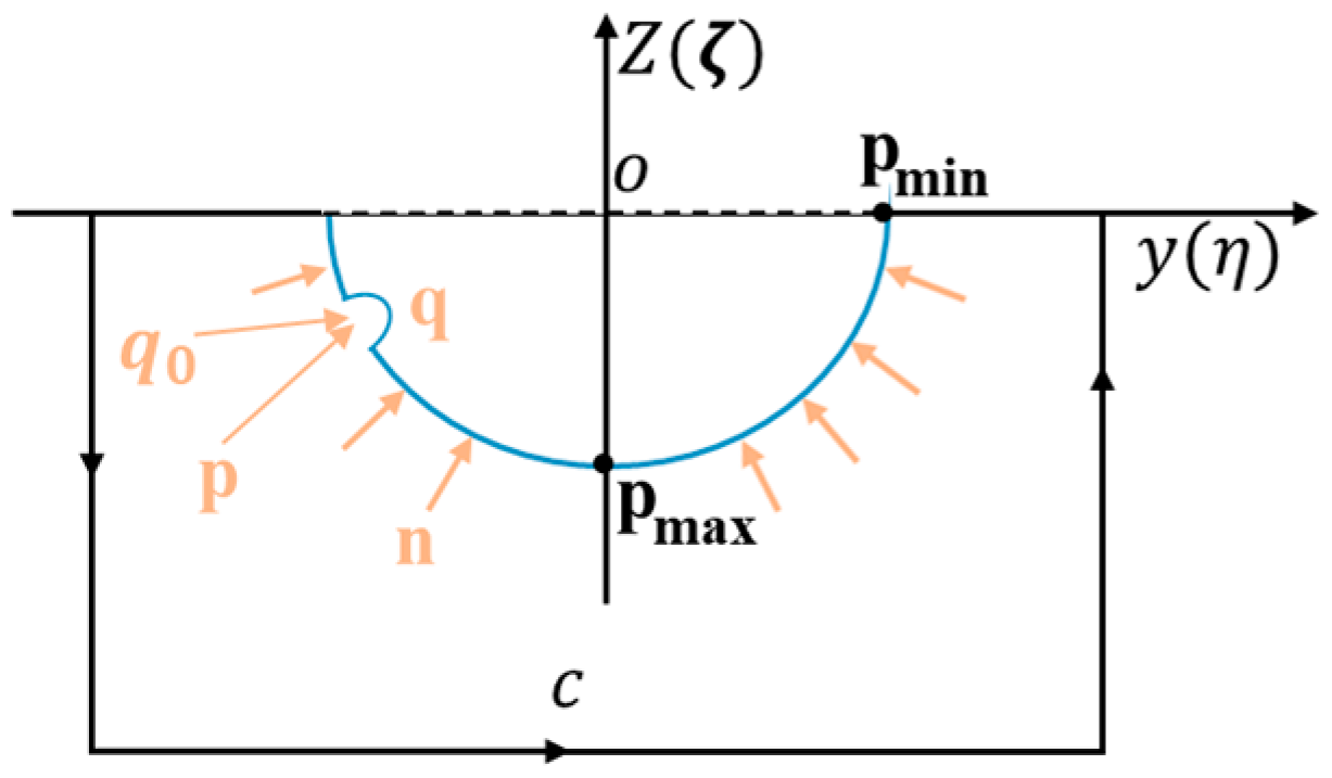
ϕ p = 1 2 π c ϕ q   G p , q N q G ϕ q N q   d l  
where c is the flow field boundary curve, and its direction is shown in Figure 2, with the normal direction pointing to the outside of the flow field.
The distributed source model is expressed as follows:
ϕ p = 1 2 π c 0 σ q G p , q d l
where σ q denotes the distributed source intensity.
Applying the object surface condition to discretize and solve, we obtain the following:
ϕ p n = 1 2 π i = 1 N σ i   Δ c i G p n , q d l
Substituting the obtained σ n (n = 1, 2, …, N) into the above formula, we obtain the velocity potential Φ j distribution on the surface of the object.

2.2. Turbine Rotor System Model

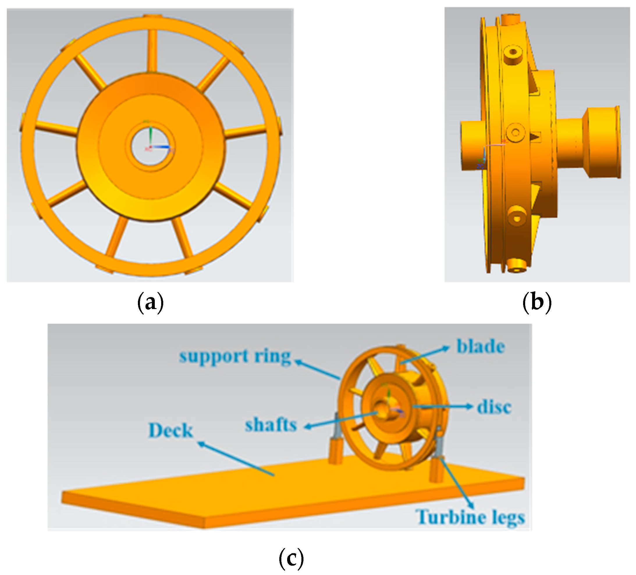
In order to reduce the cost of modeling and calculation, a simplified power turbine support ring is established by ensuring that the relevant components on the simulation software ABAQUS 2021 load transfer path remain unchanged, removing the characteristics of holes, chamfers, screw nuts, etc. The simplified model is shown in Figure 3.
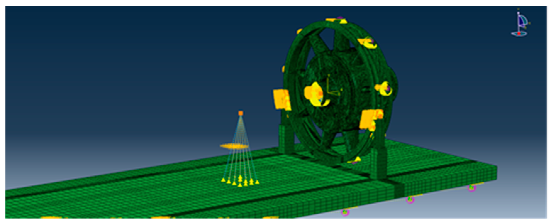
Taking into account the isolation effect due to the inherent elasticity of the base in the gas turbine rotor system, 32 vibration isolators were installed on the surface of the bottom plate to simulate marine environments, coupled at the center point of the bottom plate, and the accelerations in the X and Z directions were set at the coupled point, and the test data were imported to simulate different marine environments. The corresponding front and rear bearing position points were set, coupled with the bottom plate and the inner ring of the rear bearing, respectively, and mass points were applied to them to simulate the mass of the turbine support, as shown in Figure 4.

2.3. Vibration Transmission Model

Considering the dynamic response of the gas turbine rotor system and the hull excitation to the rotor system, the rigid ring element, and the excitation force at the bottom of the turbine rotor system, we obtain the overall motion equation of the gas turbine rotor system:
M U ¨ + G + C U ˙ + K U = Q d + Q g
where M represents the mass matrix of the turbine rotor system, G denotes the gyroscopic force matrix of the turbine rotor system, Q d is the acceleration load in the X and Z directions, the damping matrix is represented by C, the stiffness matrix is represented by K, Q g is the gravity of the system, and U ¨ ,   U ˙ ,   U represent the acceleration, velocity, and displacement of the system, respectively.
The homogeneous form of Equation (9) is as follows:
M U ¨ + C U ˙ + K U = 0
The damping term C in Equation (10) already includes the gyroscopic moment term.
The characteristic equation of the above equation is the following:
λ 2 M + λ C + K U 0 = 0
where λ is the complex eigenvalue.
Linearizing Equation (10), we obtain
Ψ = U ˙ U ,   A = M 0 0 K ,   B = C K K 0
Then, Equation (10) can be equivalent to
A Ψ ˙ + B Ψ = 0
The characteristic equation is the following:
λ A + B Ψ 0 = 0
where λ is a complex number related to the rotational speed (i represents an imaginary unit, and j = 1, 2, …, 4n). The precession frequency is represented by ω j , and, when ω = Ω , we obtain the critical speed. The special solution of Equation (9) is as follows:
U = U A e i Ω t + U B e i Ω t
Substituting Equation (15) into Equation (9), we obtain the following:
M Ω 2 + i Ω C + K U A = Q A M Ω 2 i Ω C + K U B = Q B
By solving the above equation, we can obtain the response of the turbine rotor system.

2.4. Vibration Transmission Analysis of Fusion Model

In order to truly simulate the ship’s sway, vibration, and transmission, the boundary conditions of the turbine rotor system are set to constrain all angular degrees of freedom while retaining the displacement degrees of freedom in three directions. The inner ring surface of the sliding bearing is rigidly coupled with the bearing point to better reflect the acceleration load characteristics at the bearing point. The equivalent mass point of the rotor mass is applied at the bearing point.
Combined with the stiffness test results of the support damping plate, the stiffness and damping of the shock absorber, and the natural frequency modal test of the whole machine, the three-dimensional dynamic model of the vibration transmission of the whole machine is modified through material damping and a critical boundary, which is used as the model for vibration evaluation at the bearing point.
The material used is structural steel, the material damping is 0.1, and, as the material damping increases, the structure’s ability to suppress vibrations is enhanced, resulting in smaller vibration amplitudes. The vibration isolator damping coefficient is 100, and a higher damping coefficient in the vibration isolator makes it more effective in absorbing and reducing the transmission of vibrations. The thermal expansion coefficient is 1.34 × 10⁻⁵ (mm unit system). With a larger thermal expansion coefficient, dimensional changes due to temperature variations become more pronounced.
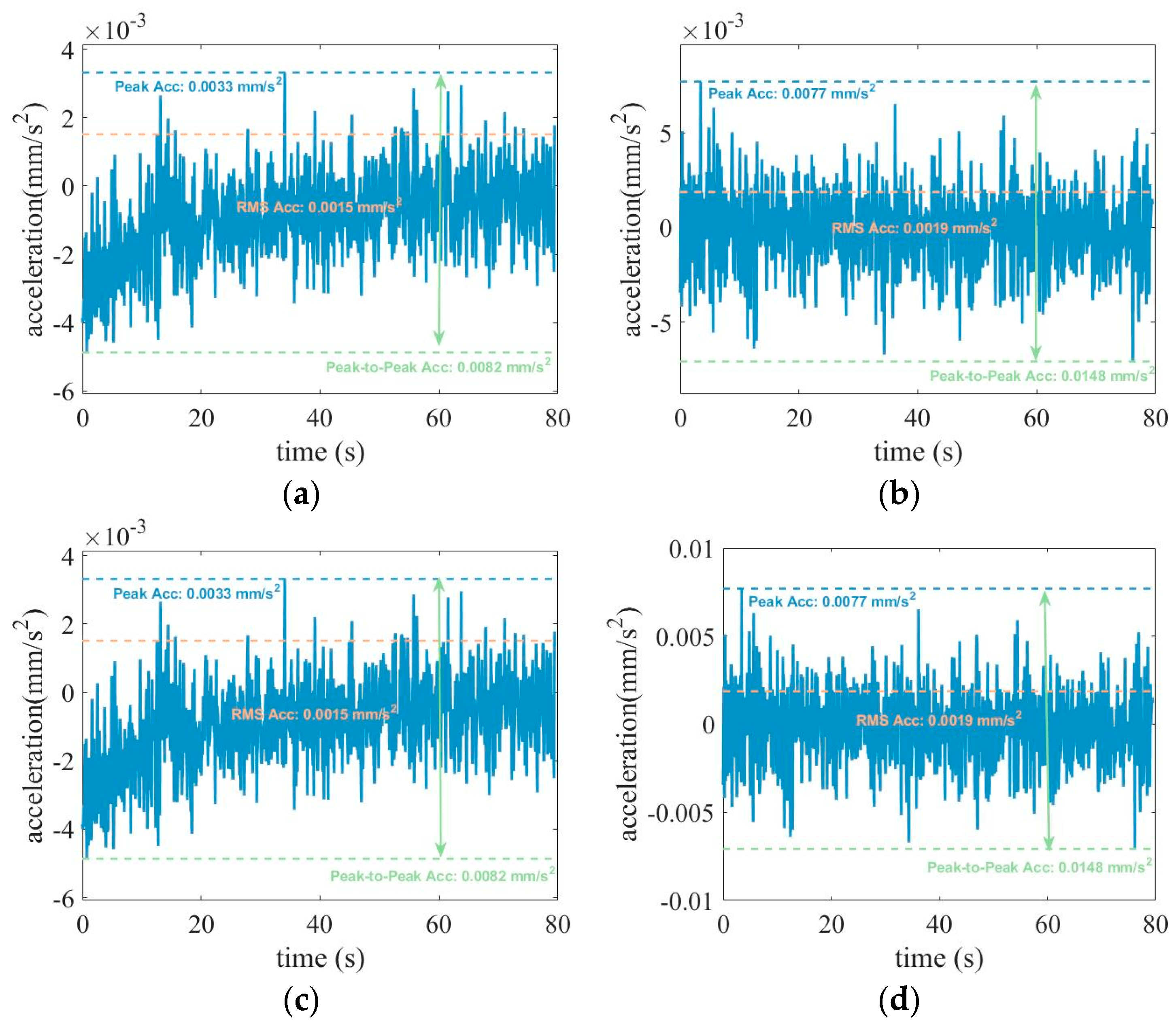
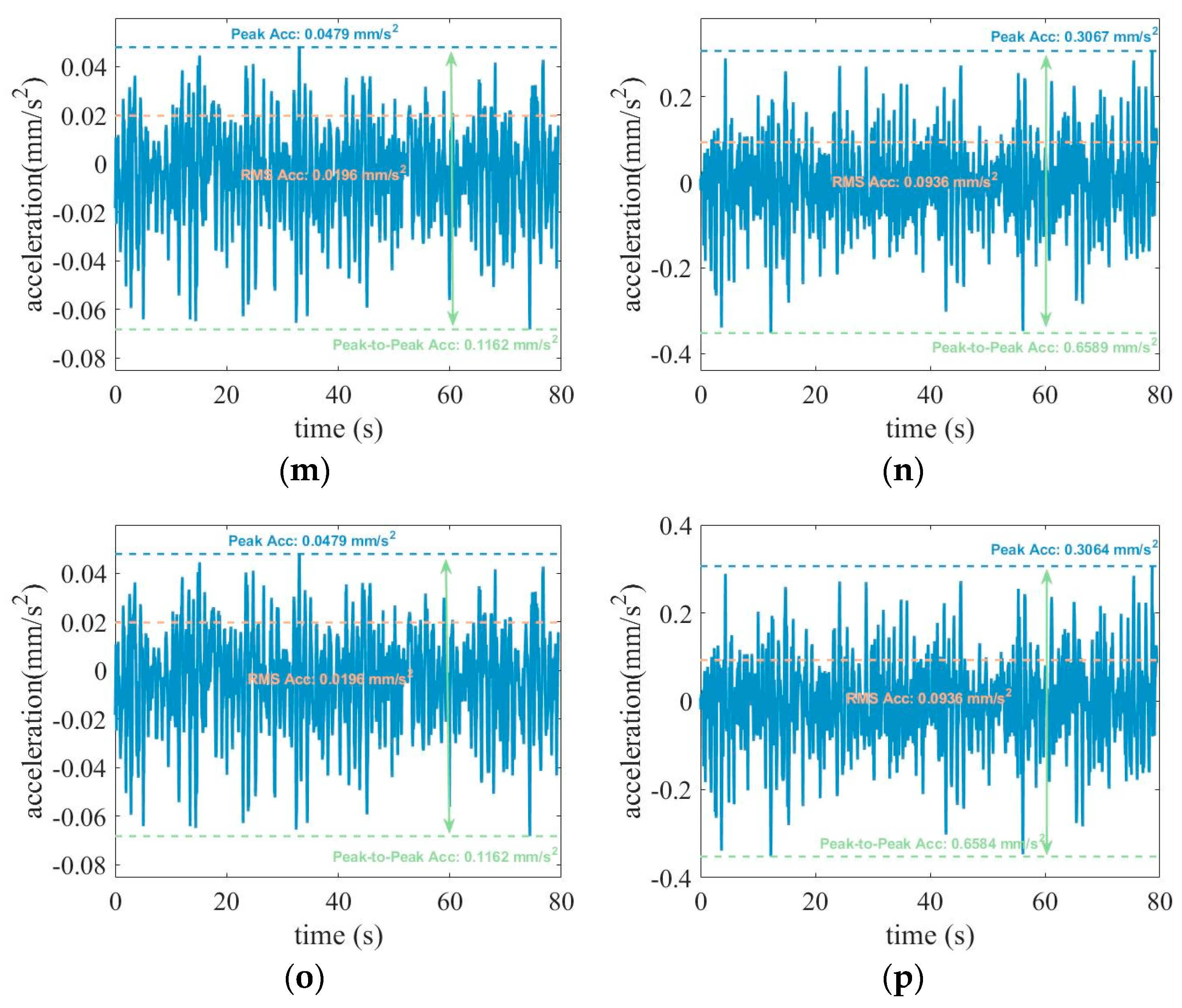
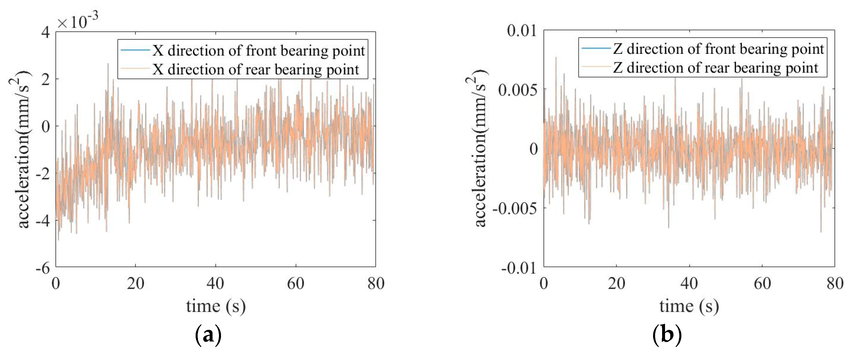
After wavelet noise reduction, Fast Fourier Transform, signal resampling and other technologies were applied to the loads with significant wave heights of 0.5 m, 1.25 m, 2.5 m, and 4 m obtained from the ship model test, and the loads were transmitted to the deck bottom of the turbine support system to calculate the vibration response through the deck, support system, and turbine to the front and rear bearing points. The calculation results are shown in Figure 5:
As shown in Figure 5, the front and rear bearing points exhibit oscillatory behavior over time both in the X and Z directions. In the X direction, the waveforms at the front and rear bearing points are essentially identical for significant wave heights of 0.5 m, 1.25 m, 2.5 m, and 4 m, with the corresponding peak values, effective values, and peak-to-peak values being largely consistent. Similarly, in the Z direction, the waveforms at the front and rear bearing points are essentially identical for significant wave heights of 0.5 m, 1.25 m, 2.5 m, and 4 m, with the corresponding peak values, effective values, and peak-to-peak values being largely consistent. The comparison of curves and their peak values, effective values, and peak-to-peak values reveals that the vibration signals at the front and rear bearing points in the Z direction are stronger than those in the X direction. Moreover, as the significant wave height increases, so do the associated peak values, effective values, and peak-to-peak values. The comparison of the vibration response ratios for different significant wave heights indicates that, when the significant wave height is 0.5 m, the vibration response ratio is significantly greater than the other groups of data. An analysis of various indicators indicates that, when the significant wave height is 0.5 m, the vibration signal in the X direction exhibits a more significant response change than that in the Z direction, resulting in a change in the dynamic response characteristics of the system and leading to the maximum vibration response ratio. Furthermore, the comparison of the output and input signal values across all datasets shows that the output signal values are consistently lower than the input signal values due to the influence of material damping. The yawing caused by the bow waves induces the hull to move in a low-frequency and high-amplitude pattern. This motion is transmitted to the rotor system through the support system, resulting in the oscillation of the acceleration input waveform, which, in turn, leads to the acceleration at the front and rear bearing points in the X and Z directions over time.
As shown in Figure 5, the acceleration values at the front and rear bearing points in the X direction exhibit a gradual decrease from 0 to 10 s, followed by a stable state from 10 to 100 s. The acceleration waveforms at the front and rear bearing points are essentially identical. The acceleration values along the Z direction oscillate over time within 0–100 s, and the acceleration waveforms at the front and rear bearing points are basically the same. The peak values at the front and rear bearing points in the X and Z directions are slightly lower than those in the input time-domain waveforms, a result of the damping effect in the materials. The impact of head waves leads to the hull experiencing vibrations at a low frequency and high amplitude, which are then transmitted through the support system to the turbine system, causing the input acceleration waveform to oscillate. Consequently, the acceleration at the front and rear bearing points in both the X and Z directions oscillates over time.

3. Experimental Study of Fusion Model

3.1. Ship Test Model

According to the similarity law of the seakeeping test, the actual ship is scaled down to ensure geometric similarity, motion similarity, and mechanical similarity between the actual ship and the ship model, thereby ensuring the accuracy of the data measured by the ship model.
Geometric similarity means ensuring that the ship type and scale ratio of the actual ship and the ship model are the same, and the condition is as follows:
L s L m = B s B m = T s T m = α l
where L s denotes the length of the actual ship, L m represents the length of the model ship, B s is the width of the actual ship, B m is the width of the model ship, T s is the draft of the actual ship, T m is the draft of the model ship, and α l is the size ratio.
Motion similarity means ensuring that the corresponding mass points of the actual ship and the ship model move along geometrically similar trajectories and pass through a geometrically similar distance over a certain proportional time. The conditions are the following:
V s 1 V m 1 = V s 2 V m 2 = = C v
where V s is the speed of the actual ship; V m is the speed of the ship model; and subscripts 1, 2, … represent the positions of corresponding points.
Mechanical similarity means that forces at corresponding points in systems with similar geometry and motion are in the same direction and proportional to one another. In view of the complexity of mechanical phenomena and the general laws of mechanics (Newton’s Second Law of Motion—Force and Acceleration), we obtain the following:
F s = M s d v s d t s F m = M m d v m d t m
where F is the force applied to the corresponding point; and M is the mass of the hull.
Substituting the similarity constants α F , α M , α v , α t of the same physical quantities into the above equation, we obtain the following:
α F F m = α M M m α v d v m α t d t m α F α t α M α v F m = M m d v m d t m
where α F α t α M α v is the similarity index of the mechanical system. If α F α t α M α v = 1 , we obtain the following:
F s t s M s v s / F m t m M m v m = 1 or F s t s M s v s = F m t m M m v m
The swaying environment refers to the swaying motion in which the longitudinal symmetry plane of the hull always coincides with the vertical plane encompassing the ship’s sailing speed vector. It is characterized by the fact that the magnitude and direction of the gravity component in the y-axis direction of the hull will change periodically with the swaying angle during the swaying process. Consequently, this leads to a periodical change in the bearing load applied to the turbine rotor system as the hull sways.
The changing law of displacement, velocity, and acceleration when the ship is pitching, that is, the swing law of the hull pitching motion, is the following:
θ J , x = θ x , m sin 2 π ω x t + φ x , 0
θ ˙ J , x = θ x , m 2 π ω x cos 2 π ω x t + φ x , 0
θ ¨ J , x = θ x , m ( 2 π ω x ) 2 sin ω x t + φ x , 0
where ω x is the frequency of the hull’s pitch swing; θ J , x is the angular displacement of the swing; θ ˙ J , x is the speed of the swing; θ ¨ J , x is the acceleration of the swing; θ x , m is the amplitude of the swing angle; and φ x , 0 is the initial phase.
The lateral swing of the ship refers to the swinging motion of the hull rotating around its own longitudinal axis along the tangent direction of the track. It is characterized by the fact that the direction and magnitude of the gravity components both in the X-axis and Y-axis directions will change periodically with the lateral rolling motion of the hull, which leads to a periodic change in the bearing load applied to the turbine rotor system as the hull swings.
θ J , z = θ z , m sin 2 π ω z t + φ z , 0
θ ˙ J , z = θ z , m 2 π ω z cos 2 π ω z t + φ z , 0
θ ¨ J , z = θ z , m ( 2 π ω z ) 2 sin ω z t + φ z , 0
where ω z is the frequency of the ship’s roll motion; θ J , z is the angular displacement; θ ˙ J , z is the speed; θ ¨ J , z is the acceleration; θ z , m is the amplitude; and φ z , 0 is the initial phase. In general, when the ship’s roll motion occurs, θ J , z 0 ,   θ ˙ J , z 0 ,   θ ¨ J , z 0 ,   Z · J changes, and other motion parameters are zero.
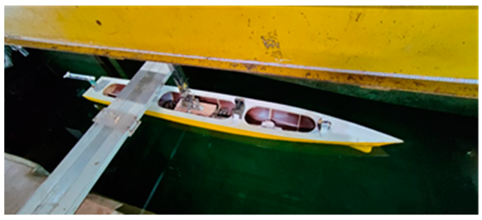
The ship model scaled down based on a certain ratio is shown in Figure 6. The lateral moment of inertia of the ship model is 0.06 Kgf·5 m·s2, and the longitudinal moment of inertia is 21 Kgf·5 m·s2, which ensures the dynamic similarity with the actual ship at the same scale.

3.2. Ship Test Analysis

This test was conducted in a towing tank that is 108 m long, 83 m effective, 7.0 m wide, and 3.4 m deep. SW-3, a three-dimensional wave-maker pusher imported from Denmark, was installed at the end of the tank, and a ship model dock and wave-breaking bank were set at the head of the tank. The measurement system was a four-degree-of-freedom seakeeping instrument, GEL-421-1. The models, ranges, and accuracy of each device are shown in Table 1.
The test process and measurement system are shown in Figure 7.
During navigation, the majority of encountered sea waves have significant wave heights ranging from 0.5 m to 3 m. To simulate varying marine environmental conditions, four test conditions were established with significant wave heights of 0.5 m, 1.25 m, 2.5 m, and 4 m, respectively, while maintaining the pool water temperature at 20 degrees Celsius. These wave heights cover conditions ranging from calm waters to higher waves, enabling the evaluation of the performance and structural response of the target model under a variety of fluctuating conditions. The above conditions measured the heave and pitch motion of the target model and the motion acceleration values (in the x, y, and z directions) at designated key positions (deck, front bearing, and rear bearing).
Acceleration sensors are arranged at the center of gravity and the key position of the gas turbine. The acceleration at the center of gravity can be used to obtain the acceleration at any position through coordinate conversion relations. Different acceleration sensors can verify the reliability of data records.
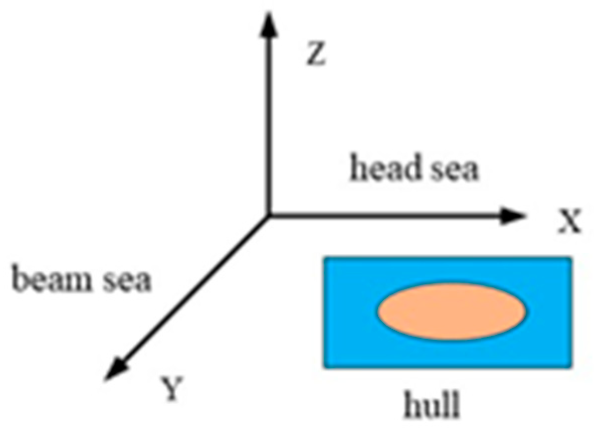
The test direction of the turbine rotor system facing the waves is shown in Figure 8. Upon encountering head waves, the hull is subjected to wave forces in the X and Z directions. At this time, the acceleration of the waves in the X and Z directions is significantly greater than that in the Y direction. From the perspective of computational efficiency, the turbine rotor system only retains the wave acceleration input in the X direction and the Z direction when encountering the head sea.
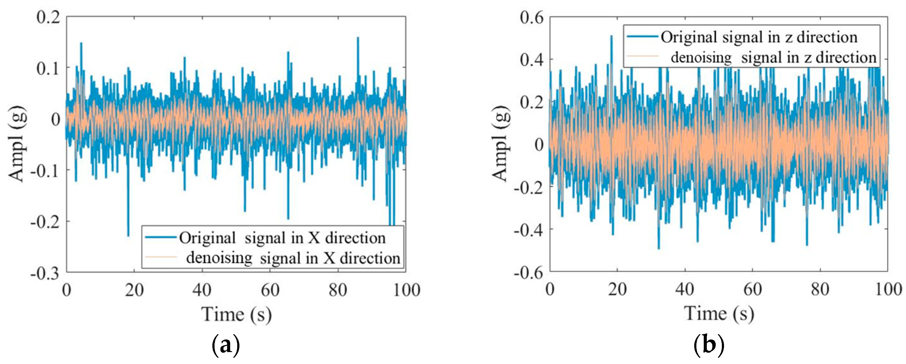
The sampling frequency of the original data, 10,000 Hz, poses challenges for quick and effective computation in three-dimensional simulation software. In addition, the presence of high-frequency noise in the original data may interfere with the study of low-frequency and high-amplitude vibration transmission of the hull swing. Processing of the original data is necessary. Firstly, an analysis of the time–frequency domain characteristics of the original signal is required. Given that the turbine’s acceleration in the X and Z directions is substantially greater than that in the Y direction during head-on wave conditions, only the acceleration in the X and Z directions is retained for computational efficiency. The time-domain signals in the X and Z directions are amplified individually, and a 10 s segment of these signals is selected to produce 10 s time-domain signals in the X and Z directions as depicted in Figure 9.
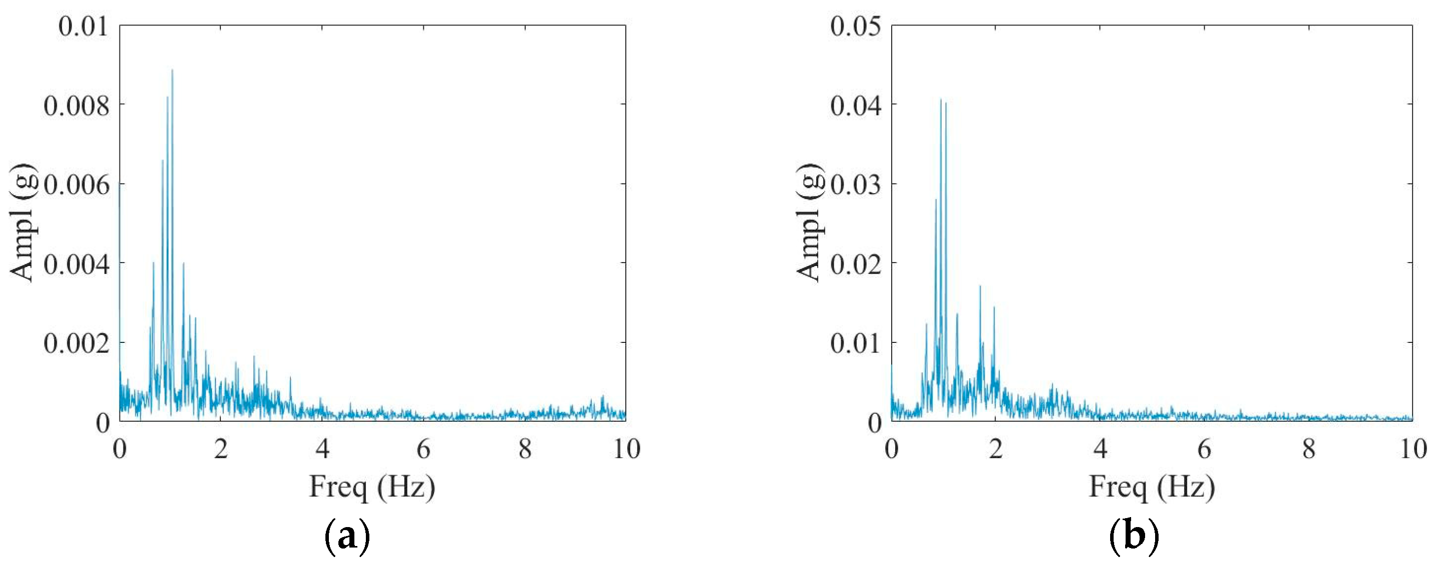
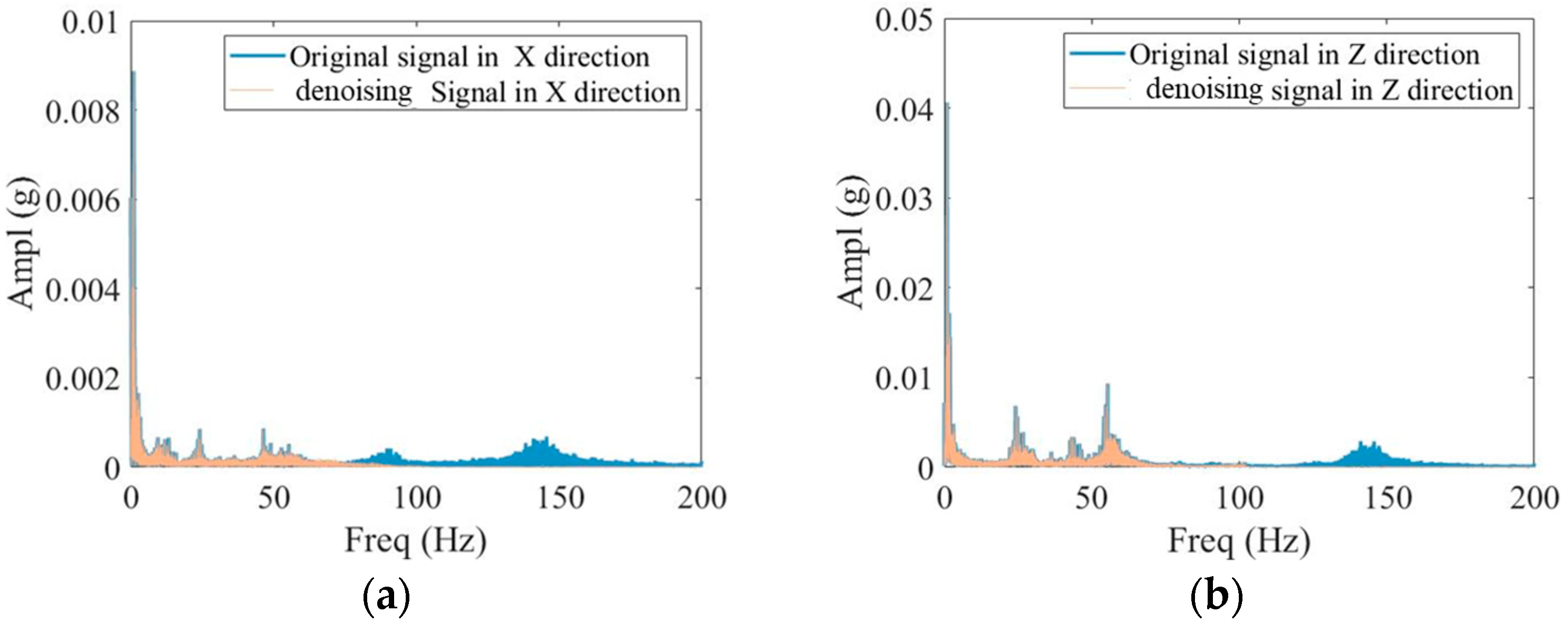
The FFT on the acceleration in the X and Z directions indicates that the acceleration in the two directions has high-frequency components superimposed on the low-frequency vibration (about 1 Hz, below 2 Hz), as shown in Figure 10.
Secondly, the wavelet transform method is employed to denoise the original signal of the acceleration input in the X and Z directions of the turbine support, filter out the high-frequency components, and retain the low-frequency components. Figure 11 illustrates the comparison between the denoised signal and the original signal trajectory. The denoised signal exhibits greater smoothness, with the low-frequency components below 10 Hz remaining largely consistent with the original signal.
The FFT on the acceleration after noise reduction in the X and Z directions indicates that the acceleration in the two directions has high-frequency components superimposed on the low-frequency vibration (about 1 Hz, below 2 Hz), as shown in Figure 12.
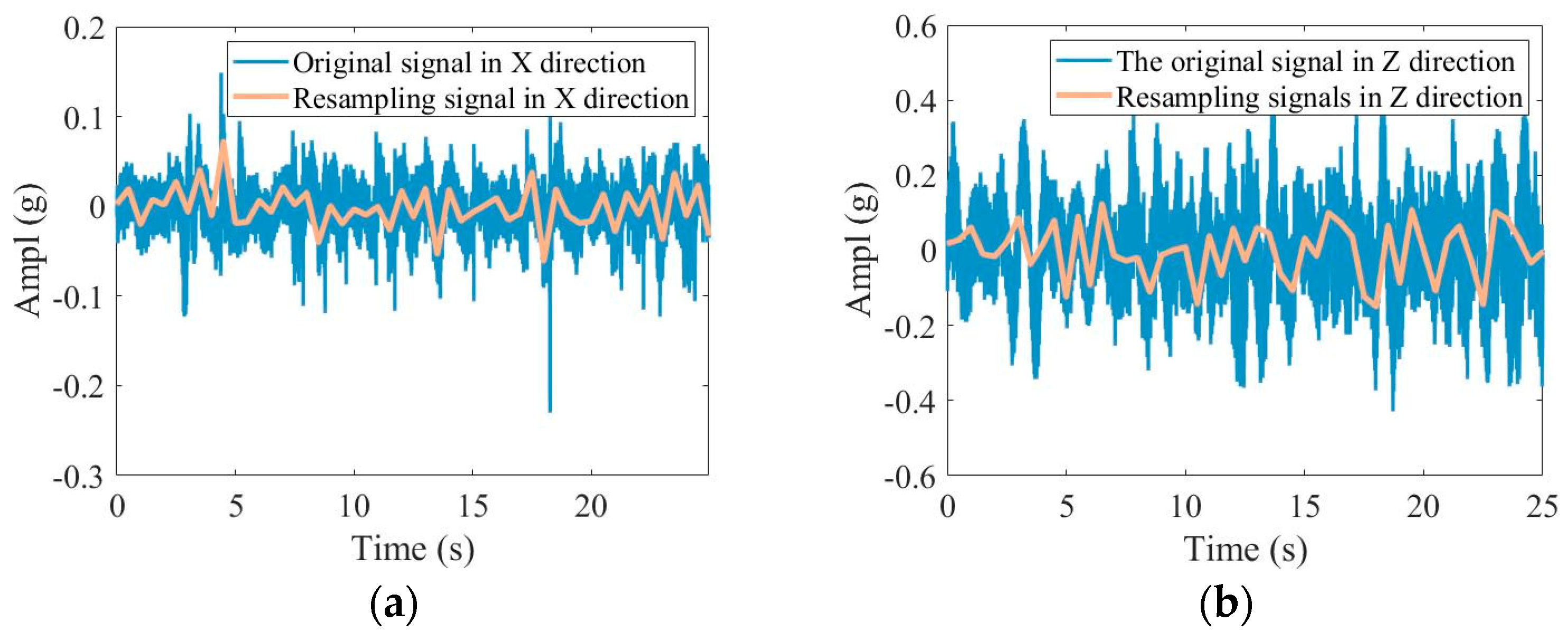
Finally, since the sampling frequency in the test is 10 k, even if the signal data after noise reduction still require large calculations for simulation measurements, the denoised signal within 100 s is resampled, with a resampling frequency of 20 Hz, ensuring 10 points per cycle of the 2 Hz signal. The time trajectories of the resampled signal and the denoised signal are compared. Due to the reduction in the number of sampling points, the comparison of the time domain and the frequency domain is slightly different but largely consistent, as shown in Figure 13.

4. Comparative Analysis of Fusion Models

4.1. Acceleration Response

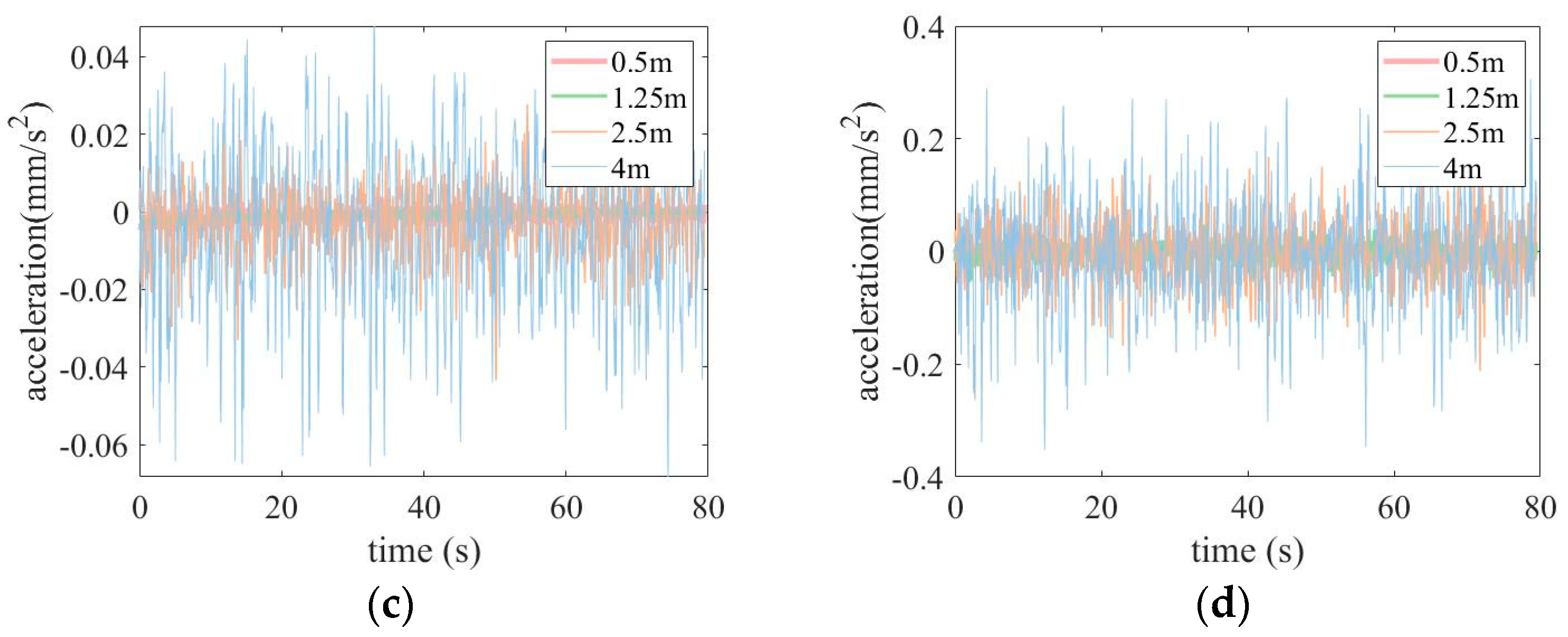
The comparison of the changes in vibration signals at significant wave heights of 0.5 m, 1.25 m, 2.5 m, and 4 m, as shown in Figure 14a–d, indicates that the vibration response waveforms at different significant wave heights are basically the same. The peak-to-peak values of the vibration signals at different significant wave heights are as follows: 0.008187, 0.007223, 0.071158, and 0.116176 in Figure 14a, 0.014786, 0.128267, 0.381124, and 0.658892 in Figure 14b, 0.008184, 0.007219, 0.071155, and 0.116171 in Figure 14c, and 0.014768, 0.128132, 0.380733, and 0.658445 in Figure 14d. This comparison indicates that, as the significant wave height increases, so does the peak-to-peak value of the vibration signal.
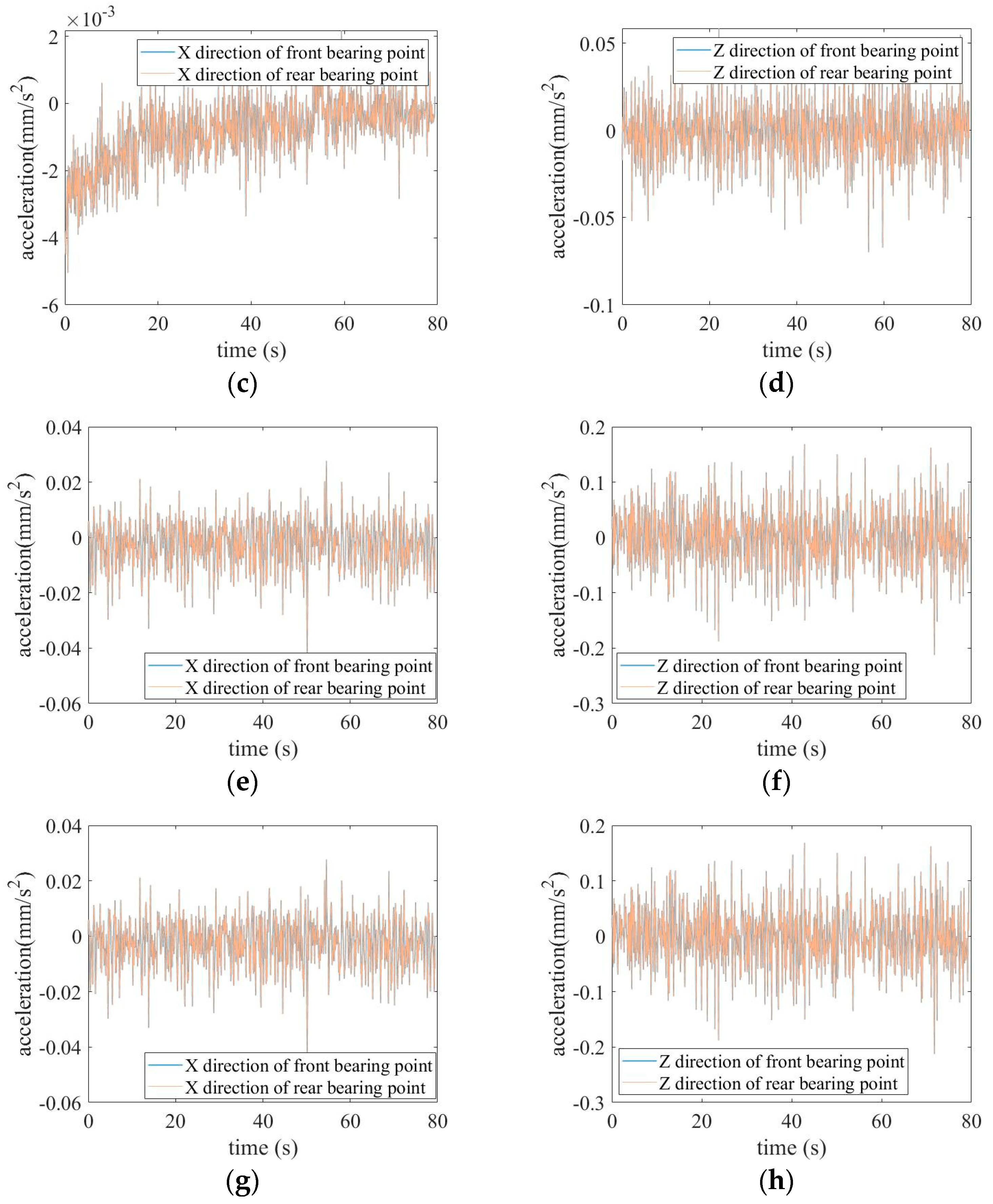
The comparison of the changes in vibration signals at the front and rear bearing points, as shown in Figure 15a–h, reveals that the vibration response waveforms at the front and rear bearing points in the X and Z directions are generally consistent. The effective values of the vibration signal are as follows: 0.001511 and 0.001510 in Figure 15a, 0.001866 and 0.001865 in Figure 15b, 0.001262 and 0.001261 in Figure 15c, 0.015221 and 0.015213 in Figure 15d, 0.008563 and 0.008563 in Figure 15e, 0.048041 and 0.048020 in Figure 15f, 0.019646 and 0.019645 in Figure 15g, and 0.093615 and 0.093584 in Figure 15h The comparison of the effective values of the vibration signals at the front and rear bearing points indicates that the amplitude of the vibration signal at the front bearing point is slightly larger than at the rear bearing point. Specifically, the effective value of the vibration signal at the front bearing point in the X direction is 0.03~0.10% larger than at the rear bearing point, and the effective value of the vibration signal at the front bearing point in the Z direction is 0.03~0.04% larger than at the rear bearing point. This suggests that the damping of the low-frequency and high-amplitude vibrations transmitted to the front bearing through the support system is relatively less than that transmitted to the rear bearing.

4.2. Root Mean Square (RMS) Acceleration

The wave load waveforms under different significant wave heights are relatively complex. By calculating the RMS values of the acceleration at the front and rear bearing points before and after the wave test and simulation, we can roughly gauge the overall vibration intensity and the energy contained in the vibration signals.
(1)
Front Bearing Point
The RMS values of the acceleration output responses from the simulation and test results in the X and Z directions at the front bearing point are calculated, respectively. The calculation results are presented in Table 2.
(2)
Rear Bearing Point
The RMS values of the acceleration output responses from the simulation and test results in the X and Z directions at the rear bearing point are calculated, respectively. The calculation results are presented in Table 3.
By calculating the RMS value comparison error of the acceleration load at the front and rear sliding bearings, we found that the RMS value errors of the turbine in the X and Z directions are about 10% under 18-knot head waves, which verifies the feasibility and correctness of the fusion model. The RMS value of the Z reverse acceleration is greater than the RMS value in the X direction, indicating that the vibration intensity in the Z direction is greater.

5. Conclusions

In this paper, the vibration transmission model integrating a ship model slice, test data, and a three-dimensional entity is proposed. Techniques including wavelet denoising, Fast Fourier Transform, and signal resampling are used, and the simulation is carried out by numerical calculation and a display algorithm. The vibration response tests were carried out under effective wave heights of 0.5 m, 1.25 m, 2.5 m, and 4 m. The test results and simulation results were compared.
  • A simplified three-dimensional entity model of the turbine support ring was developed. The three-dimensional dynamic model for the whole machine vibration transmission was modified by material damping and a critical boundary. A ship slice model was developed based on the two-dimensional slice theory. A fusion model was constructed by combining the ship model test data. The acceleration response and RMS value were compared to validate the accuracy of the model.
  • The high acceleration amplitude observed in the 1–2 Hz frequency range in the X and Z directions of the 18-knot head wave test was primarily due to the hull experiencing low-frequency and high-amplitude motion in the vertical, front, rear, and roll directions under the influence of head waves.
  • Under the influence of a head wave load, the vibration output response at the bearing point before and after the wave load was calculated using the vibration transmission fusion model. The comparative test showed that the waveforms of the two were essentially the same. However, the obtained peak values of the vibration signal were slightly diminished compared to the input signal due to the effect of material damping. When the effective wave height was 0.5 m, the vibration response ratio outpaced the rest of the dataset. This was attributed to the change in the dynamic response characteristics under the action of the wave load, and the wave height was 0.5 m. Compared with the change in the vibration signal in the Z direction, the change in the vibration signal in the X direction produced a more obvious response. Specifically, the vibration signal in the Z direction was larger than that in the X direction. Furthermore, the amplitude of the vibration signal at the front bearing point was slightly higher than that at the rear bearing point.
The vibration transmission model integrating a ship model slice, test data, and a three-dimensional entity proposed in this paper addresses the following challenges: the difficulty in obtaining the dynamic parameters of the bearing of the turbine rotor system by hull excitation; the limitations of using a simplified sine wave in simulations to accurately represent the impact of real ocean waves on the hull; and the challenges in controlling a significant wave height level by the measured data of a real ship test. Additionally, the model tackles issues such as high sampling frequencies of the test signals, low computational efficiency, and high levels of high-frequency signal interference. This model provides reliable and accurate ideas and methods for obtaining the dynamic parameters of the bearing in the gas turbine rotor system, thereby elucidating the dynamic characteristics of the gas turbine rotor system under hull excitation. This, in turn, offers a theoretical basis for the dynamic design of the bearing and the stable operation of the gas turbine rotor system.

Author Contributions

Methodology, Q.W.; resources, Y.L.; writing—original draft, X.Z.; and writing—review and editing, X.Z., Y.L., Q.W., Z.X. and M.L. All the authors were informed about each step of manuscript processing including submission, revision, revision reminder, etc., via emails from MDPI’s system or their assigned Assistant Editor. All authors have read and agreed to the published version of the manuscript.

Funding

This research was funded by the Basic Research for National Science and Technology Major Projects of China (grant no. J2019-I-0012-0012 and grant no. HT-J2019-Ⅳ-0021-0089).

Data Availability Statement

The raw data supporting the conclusions of this article will be made available by the authors on request.

Conflicts of Interest

The authors declare no conflicts of interest.

Abbreviations

FFTFast Fourier Transform
RMSRoot mean square

References

  1. Gandzha, S.; Nikolay, N.; Chuyduk, I.; Salovat, S. Design of a Combined Magnetic and Gas Dynamic Bearing for High-Speed Micro-Gas Turbine Power Plants with an Axial Gap Brushless Generator. Processes 2022, 10, 1067. [Google Scholar] [CrossRef]
  2. Li, C. Analysis of the Misalignment-Imbalance Fault Characteristics and the Influence of Oil Inlet Pressure on the Elliptical Bearing Rotor System. Ph.D. Thesis, Xi’an University of Technology, Xi’an, China, 2022. [Google Scholar]
  3. Yuan, Z.; Shevchenko, S.; Radchenko, M.; Shevchenko, O.; Pavlenko, A.; Radchenko, A.; Radchenko, R. Studies on Improving Seals for Enhancing the Vibration and Environmental Safety of Rotary Machines. Vibration 2024, 7, 776–790. [Google Scholar] [CrossRef]
  4. Ren, Y.; Sun, X.; Luo, Y.; Lu, W.; Wang, H. Layering Vibration Transfer Path Analysis of a Flexible Supported Gear System Based on the Vibration Power Flow Theory. Processes 2023, 11, 1233. [Google Scholar] [CrossRef]
  5. Żywica, G.; Breńkacz, Ł.; Bagiński, P. Interactions in the Rotor-Bearings-Support Structure System of the Multi-stage ORC Microturbine. J. Vib. Eng. Technol. 2018, 6, 369–377. [Google Scholar] [CrossRef]
  6. Xie, C. Dynamic Characteristics Analysis of Floating Ring Bearing in Turbocharger Rotor System. Ph.D. Thesis, Taiyuan University of Science and Technology, Taiyuan, China, 2021. [Google Scholar]
  7. Zhang, J.; Fu, Z.; Yang, J.; Han, D. Experimental Investigation on the Influence of Bearing Supply Pressure on Gas Whip of the Rotor-Bearing Systems of High Speed Turbines. Noise Vib. Control 2015, 35, 195–199. [Google Scholar]
  8. Zhou, H.; Zang, C. Analysis of Dynamic Characteristics for the Rotor System in an Air Turbine Starter. Mach. Build. Autom. 2022, 51, 23–25. [Google Scholar]
  9. Wu, G. Research on Fault Excitation and Transmission Characteristics of Gas Turbine Rolling Bearings. Ph.D. Thesis, Harbin Institute of Technology, Harbin, China, 2021. [Google Scholar]
  10. Li, J. Research on Dynamic Stability of Two-Stage Turbine Bearing-Rotor System. Ph.D. Thesis, University of Chinese Academy of Sciences (The Institute of Engineering Thermophysics, Chinese Academy of Sciences), Beijing, China, 2018. [Google Scholar]
  11. Huang, Z.; Yuan, Q.; Yu, C.; Gao, J.; Kong, X. Research on Design Methodology for Similarity Test Model of Gas Turbine Rotor Dynamics. J. Xi’an Jiaotong Univ. 2023, 57, 78–88. [Google Scholar]
  12. Lei, D. Analysis of Coupled Vibration Characteristics of Aviation Turbine Engine Rotor-Helical Gear System. Ph.D. Thesis, Central South University, Changsha, China, 2022. [Google Scholar]
  13. Zhang, L.; Pei, S.; Xu, H. Research on Safety and Stability of Two Ship Rotor Bearing Systems under Swing Conditions. Sci. Sin. (Technol.) 2018, 48, 369–381. [Google Scholar] [CrossRef]
  14. Han, Q.; Chu, F. Parametric instability of flexible rotor-bearing system under time-periodic base angular motions. Appl. Math. Model. 2015, 39, 4511–4522. [Google Scholar] [CrossRef]
  15. Pu, S.; He, Y.; Yang, Q.; Cheng, M.; Wang, Y.; Wang, Z.; Lin, Y. Study on Dynamic Characteristics of Rotor-Bearing System under Pitching Condition. J. Phys. Conf. Series. IOP Publ. 2021, 2113, 012021. [Google Scholar] [CrossRef]
  16. Wang, Z. Analysis and Experimental Study on Oil Film Characteristics of Ship Plain Bearing. Ph.D. Thesis, Zhejiang Ocean University, Zhoushan, China, 2023. [Google Scholar]
  17. Li, X.; Zhang, G.; Yang, Y. Kinematics Analysis of the 6-DOF Test-bed for the Sliding Bearing of Marine Gas Turbine. J. Phys. Conf. Series. IOP Publ. 2021, 1952, 032002. [Google Scholar] [CrossRef]
  18. Ding, K. Research on Design of Ship Plain Bearing-Rotor Test Platform and Swing Test. Ph.D. Thesis, Zhejiang Ocean University, Zhoushan, China, 2023. [Google Scholar]
  19. Wang, Q.; Xing, Z.; Liu, Y.; Li, M. Rubbing vibration characteristics of double-rotor system under wave load. J. Vibroeng. 2023, 25, 1–14. [Google Scholar] [CrossRef]
  20. Zeng, F.; Liu, Y.; Wang, Q.; Li, J. Simulation analysis of rolling bearings based on explicit dynamics. J. Phys. Conf. Series. IOP Publ. 2022, 2383, 012158. [Google Scholar] [CrossRef]
  21. Yang, W.; Liang, M.; Wang, L.; Yuan, H. Research on unbalance response characteristics of gas turbine blade-disk rotor system. J. Vibroeng. 2018, 20, 1676–1690. [Google Scholar] [CrossRef]
Figure 1. Vibration transmission model of ship model slice–test data–3D entity integration.
Processes 12 02091 g001
Figure 2. Schematic diagram of the coordinate system of a two-dimensional cylinder section.
Processes 12 02091 g002
Figure 3. Simplified turbine support system model: (a) front view of the model; (b) side view of the model; and (c) overall system model.
Processes 12 02091 g003
Figure 4. Position and setting of front and rear bearings.
Processes 12 02091 g004
Figure 5. Vibration response of front and rear bearing points: (a) acceleration of the front bearing point in the X direction at a meaningful wave height of 0.5 m; (b) acceleration of the front bearing point in the Z direction at a meaningful wave height of 0.5 m; (c) acceleration of the rear bearing point in the X direction at a meaningful wave height of 0.5 m; (d) acceleration of the rear bearing point in the Z direction at a meaningful wave height of 0.5 m; (e) acceleration of the front bearing point in the X direction at a meaningful wave height of 1.25 m; (f) acceleration of the front bearing point in the Z direction at a meaningful wave height of 1.25 m; (g) acceleration of the rear bearing point in the X direction at a meaningful wave height of 1.25 m; (h) acceleration of the rear bearing point in the Z direction at a meaningful wave height of 1.25 m; (i) acceleration of the front bearing point in the X direction at a meaningful wave height of 2.5 m; (j) acceleration of the front bearing point in the Z direction at a meaningful wave height of 2.5 m; (k) acceleration of the rear bearing point in the X direction at a meaningful wave height of 2.5 m; (l) acceleration of the rear bearing point in the Z direction at a meaningful wave height of 2.5 m; (m) acceleration of the front bearing point in the X direction at a meaningful wave height of 4 m; (n) acceleration of the front bearing point in the Z direction at a meaningful wave height of 4 m; (o) acceleration of the rear bearing point in the X direction at a meaningful wave height of 4 m; and (p) acceleration of the rear bearing point in the Z direction at a meaningful wave height of 4 m.
Processes 12 02091 g005aProcesses 12 02091 g005bProcesses 12 02091 g005c
Figure 6. Ship test analysis.
Processes 12 02091 g006
Figure 7. Test process and measurement system.
Processes 12 02091 g007
Figure 8. Ship hull and head wave test direction.
Processes 12 02091 g008
Figure 9. Acceleration time-domain signals in the X and Z directions: (a) X-direction acceleration time-domain signal; and (b) Z-direction acceleration time-domain signal.
Processes 12 02091 g009
Figure 10. Acceleration FFT results in the X and Z directions: (a) X-direction acceleration frequency-domain signal; and (b) Z-direction acceleration frequency-domain signal.
Processes 12 02091 g010
Figure 11. Time-domain signal after noise reduction in the X and Z directions: (a) time-domain signal after X-direction noise reduction; and (b) time-domain signal after Z-direction noise reduction.
Processes 12 02091 g011
Figure 12. FFT results after the X-Z direction acceleration noise reduction: (a) frequency-domain signal after X-direction acceleration noise reduction; and (b) frequency-domain signal after Z-direction acceleration noise reduction.
Processes 12 02091 g012
Figure 13. Comparison between resampled signal and original signal: (a) resampled signal in the X direction; and (b) resampled signal in the Z direction.
Processes 12 02091 g013
Figure 14. Vibration comparison under different significant wave heights: (a) X-direction acceleration at the front bearing point under different significant wave heights; (b) Z-direction acceleration at the front bearing point under different significant wave heights; (c) X-direction acceleration of the rear bearing point under different significant wave heights; and (d) Z-direction acceleration of the rear bearing point under different significant wave heights.
Processes 12 02091 g014aProcesses 12 02091 g014b
Figure 15. Vibration comparison under different significant wave heights: (a) X-direction acceleration at a significant wave height of 0.5 m; (b) Z-direction acceleration at a significant wave height of 0.5 m; (c) X-direction acceleration at a significant wave height of 1.25 m; (d) Z-direction acceleration at a significant wave height of 1.25 m; (e) X-direction acceleration at a significant wave height of 2.5 m; (f) X-direction acceleration at a significant wave height of 2.5 m; (g) X-direction acceleration at a significant wave height of 4 m; and (h) Z-direction acceleration at a significant wave height of 4 m.
Processes 12 02091 g015aProcesses 12 02091 g015b
Table 1. List of main test instruments and equipment.
Serial NumberNameModelRangeAccuracy
1Trailer systemNon-standard
2ThermometerSWP-C80
3Airworthiness instrumentCustomizedSurge and heave range ±150 mm, roll and pitch range ±35°Displacement linear error <1.5%, resolution 0.25 mm
4Data acquisition instrumentM8128
5Acceleration sensorThree-axis piezoelectric acceleration sensor 1A342E10,000 m·s20.5 mV/m·s2
Table 2. Comparison of RMS values for head sea at front bearing points.
RMS Values of
the Simulation
Results in the X Direction
RMS Values of
the Test Results
in the X Direction
RMS Values of the
Simulation Results in the Z Direction
RMS Values of the Test Results in the Z Direction
m/s20.178036760.178036760.178036760.17803676
Error%10.827%9.949%
Table 3. Comparison of RMS values for head sea at rear bearing point.
RMS Values of
the Simulation
Results in the X Direction
RMS Values of
the Test Results
in the X Direction
RMS Values of the
Simulation Results in the Z Direction
RMS Values of the Test Results in the Z Direction
m/s20.1780345620.1780345620.1780345620.178034562
Error%10.826%9.923%
Disclaimer/Publisher’s Note: The statements, opinions and data contained in all publications are solely those of the individual author(s) and contributor(s) and not of MDPI and/or the editor(s). MDPI and/or the editor(s) disclaim responsibility for any injury to people or property resulting from any ideas, methods, instructions or products referred to in the content.