Abstract
This study aims to achieve rapid drilling of life-support holes, regarding the optimization design of drill bits as the key, among which the simulation analysis of drill bit cutting teeth is an important technical means. Firstly, based on the rock mechanics test results in the study area combined with the corresponding logging information, the analysis and evaluation of the geological conditions in the study area were completed, a complete rock mechanics characteristic profile was established, and the drillability of the rock was calculated to be relatively good. Then, a numerical simulation of parallel cutting of rock with conical teeth was established by experimentally testing rock mechanics parameters and using the discrete element method (PFC2D). The simulation study of the drill bit cutting teeth was completed by parameter calibration, analysis of rock cutting morphology, analysis of the number of rock cutting cracks, and analysis of the specific work of rock cutting and breaking. It was determined that the optimal rock-entering angle of the drill bit cutting teeth in the Shouyang mining area is 14°. Finally, verified by field practice, the optimized drill bit has stable performance, strong cutting ability, and good wear resistance; the maximum instantaneous mechanical drilling speed reaches 58.14 m/h, and it shows a slightly worn state after continuously drilling 582 m in the stratum, meeting the requirements of one-trip drilling and hole formation for life-support holes. This research provides a scientific basis and practical techniques for the construction of life-support holes in the Shouyang mining area and under similar geological conditions. It can provide more effective emergency plans and rescue strategies for possible mine disasters in the future, which is crucial for improving the technical system of emergency rescue for mine accidents and enhancing the emergency rescue capability of surface drilling.
1. Introduction
The life-support hole is an indispensable part of mine rescue. It not only provides the hope of survival for trapped miners but also provides effective rescue means for the rescuers [1,2]. Fast drilling is one of the core requirements of life-guarantee hole drilling. Specifically, the hole is formed within 72 h of gold rescue time at a depth of 600 m—that is, within 72 h, it is necessary to complete the drilling and hole fixing of the first surface soil section, the drilling and hole fixing of the second bedrock section, and the construction of the third open hole section depends on the disaster site [3]. At present, the concern for the safe and rapid drilling and trajectory control of life-support holes is mostly reflected in the application aspect [4,5,6]. Coupled with the sudden occurrence of rescue events, conventional drilling methods are often copied for operations [7,8]. There is a lack of systematic and sufficient research on the basic geological conditions in disaster areas and the adaptability of drilling techniques, resulting in slow on-site rescue operations [9,10]. Shanxi Province is one of the main coal-producing areas in China, with a relatively high risk of mine accidents [11,12]. The loose and medium–soft strata commonly existing in the region bring unique challenges to the construction of life-support holes during rescue. Given the lack of rescue experience under such special geological conditions, it is extremely important to conduct targeted preliminary research. Through these studies, more effective emergency plans and rescue strategies can be provided for possible mine disasters in the future, which can not only better protect the lives and safety of miners, but also improve the efficiency and success rate of rescue operations.
The performance of the cutting teeth of the bit directly affects the drilling efficiency of the bit [13,14]. Through simulation analysis, the design and parameters of the cutting teeth can be optimized, and the cutting speed and drilling ability of the drill bit can be improved, so as to speed up the construction progress of the life-support hole [15,16,17,18,19]. Compared with physical experiments, simulation has many advantages, such as saving time and cost, reducing material consumption, and easily adjusting various parameters in the simulation process to observe the cutting effect under different conditions [20,21,22]. In addition, simulation also allows researchers to predict and verify the performance of drill design without actually manufacturing the drill, which is particularly useful for iterative optimization of drill design [23,24,25]. At present, with the improvement in computing power and the progress of simulation technology, many research institutions and enterprises at home and abroad are using PDC bit simulation technology to obtain more accurate predictions of the rock-breaking process [26,27,28,29,30,31]. Its main research and development direction can be divided into the following two parts: The first is research on the personalized drill bit [32]; taking into account the differences in the formation, there will be personalized drills for different regions in the future to complete local optimization. The second is the improvement in simulation accuracy. With the development of computer technology, more advanced finite element models and constitutive models can be applied to construct more refined grids to complete the simulation of drill bits.
Therefore, this study selected Shouyang mining area with a relatively high risk of mine accidents as the research object. Based on the analysis and evaluation of the geological conditions in the study area, the simulation analysis of the cutting teeth of the drill bit is completed. The optimization of the rock entry angle of the drill bit is carried out in order to improve the cutting ability of the PDC bit, optimize the overall performance of the bit, and achieve the purpose of rapid rock-breaking drilling.
2. Overview of the Study Area
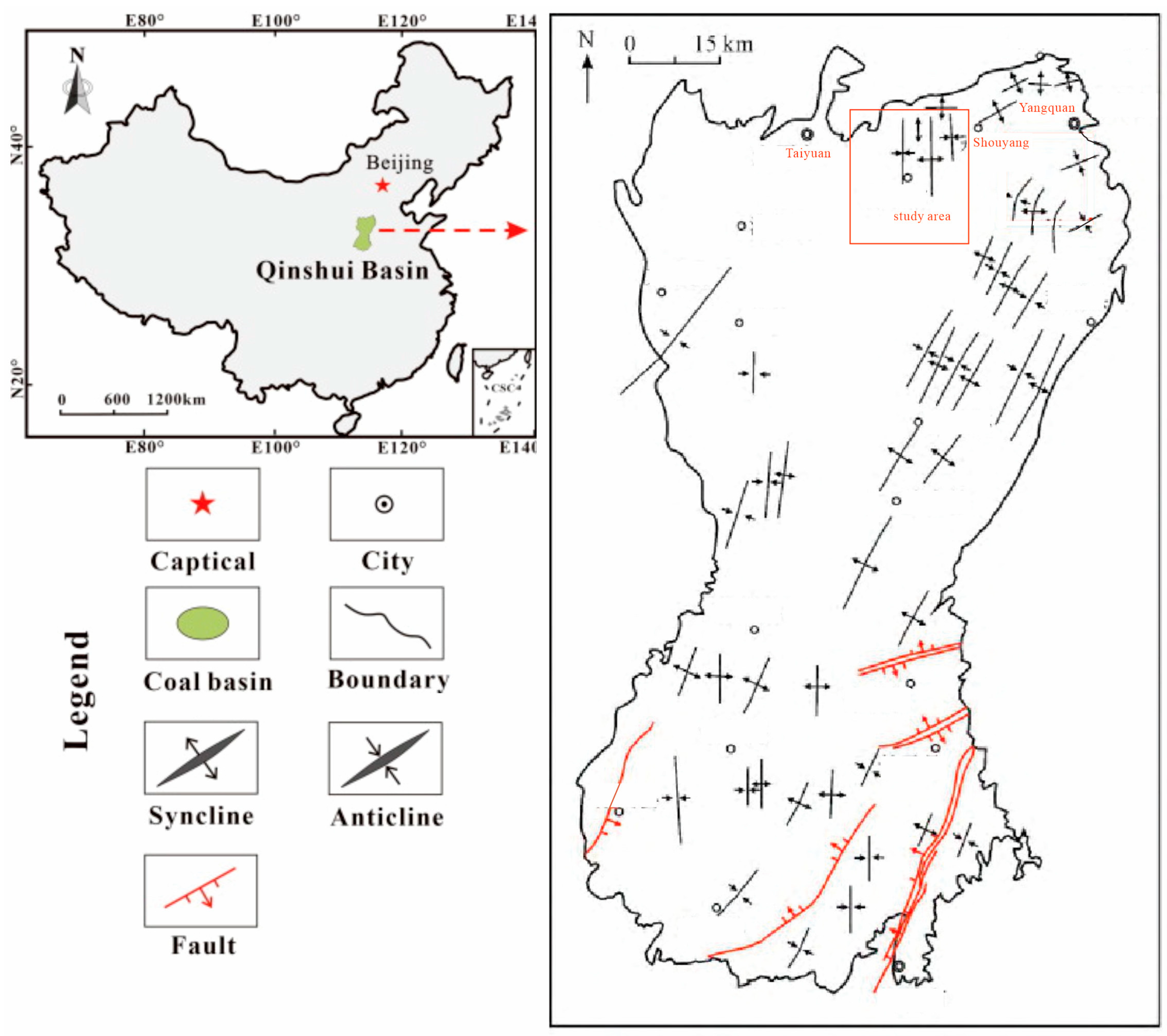
As shown in Figure 1, Shouyang mining area is located in the central part of Shanxi, at the northern end of Qinshui basin. It is mainly a monoclinic structure with an east–west trend and southward tilt, accompanied by a secondary wide and gentle fold. The dip angle of the stratum is gentle, and the middle part is steeper. The faults and collapse columns are more developed. The test area develops multiple strata, among which the Liujiagou Formation and Shiqianfeng Formation are locally developed, and the actual drilling probability is low, as shown in Table 1. Ordovician strata are usually not drilled. The main drilled strata include the Upper Shihezi Formation, which is mainly fine-grained sandstone and mudstone, while the Lower Shihezi strata are mostly feldspar quartz sandstone and mudstone interbeds, with aluminum mudstone on top. The Shanxi Formation is dominated by sandstone, mudstone, and coal seams. The Taiyuan Formation is dominated by quartz sandstone, mudstone, coal seams, and limestone.

Figure 1.
Regional location map.

Table 1.
Geological stratification of Shouyang mining area.
3. Rock Mechanics Characteristics of Strata
The mechanical characteristics of formation rock are necessary for the simulation study of drill cutting teeth [33]. It can provide the basis of real physical environment simulation so that the simulation is more in line with the actual working conditions. It is helpful to optimize the design and material selection of cutting teeth so that the cutting teeth can adapt to different rock conditions. The wear and failure modes of the cutting teeth can be predicted and improved in advance. It can also improve drilling efficiency and reduce costs, such as avoiding bit replacement and waste of drilling time. In short, it is an important factor to improve the performance of the drill bit and optimize the drilling process.
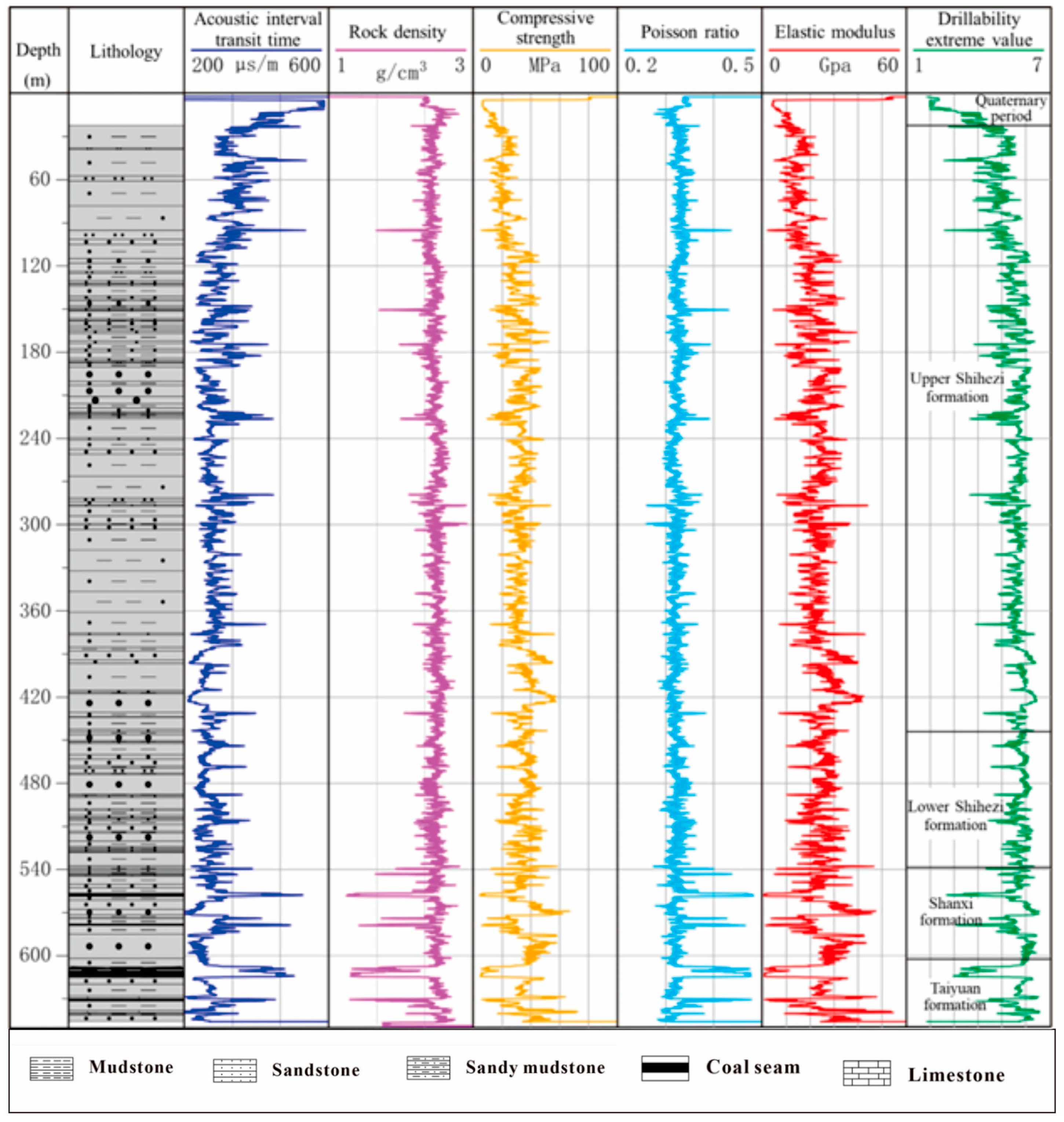
Obtaining accurate rock mechanics parameters is the basis for studying the mechanical characteristics of strata. In this study, based on the surface drilling project in the mining area, the borehole core was obtained and the specimen was reprocessed in the laboratory. The TAR-1500 hydraulic servo test system was used to carry out the whole process test of triaxial stress and strain. As shown in Table 2, it is the triaxial compression test results of the X-65 hole in Shouyang mining area. Based on the test results and the logging methods such as acoustic wave and density, the dynamic rock mechanics parameters are obtained and the complete rock mechanics characteristic profile is established. The rock drillability is calculated based on the acoustic logging method, as shown in Figure 2. All types of data extracted in the figure strictly comply with the technical standards in the “Coalbed Methane Logging Operation Regulations” (Q/CUCBM 0401—2002) issued by China United Coalbed Methane Corporation Limited. It can be seen from the figure that the Shouyang mining area is dominated by medium–fine sandstone plus mudstone and siltstone. The formation hardness is medium–soft, and the local formation is hard. The compressive strength of the bedrock formation is between 5.87 and 73.17 MPa, with an average of 33.25 MPa. The drillability grade is between 2.8 and 6.6, with an average of 5.1, and the comprehensive evaluation of drillability is good.
Table 2.
Results of triaxial compression test.
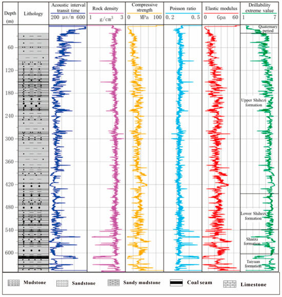
Figure 2.
Rock mechanical characteristics profile of X-65 hole formation.
4. Simulation Analysis of Drill Cutting Teeth
Engineering practice shows that PDC bits have become the preferred bit type for rescue in most areas of China due to their common advantageous characteristics and wide applicability. Their cutting teeth are the basic cutting units, and their performance directly determines the drilling effect. This paper selects the fine sandstone stratum with the highest strength in the bedrock stratum and uses PFC software 9.1 (Particle Flow Code) analysis combined with the indoor experiment method to optimize the rock-entering angle of the drill bit teeth, aiming to improve the cutting ability, optimize the overall performance, and achieve rapid rock-breaking drilling [34]. As a representative software based on discontinuous medium mechanics, PFC can not only simulate the macroscopic and mesoscopic mechanical characteristics of rock materials but also reveal the dynamic mechanical characteristics at the mesoscopic level, which can provide a reliable theoretical basis for drill bit design optimization, performance improvement, and service life extension as well as help the research and development in related fields [35,36]. In the relevant research on rock cutting, most of them focus on the essence of plastic–brittle failure and the mechanism of plastic–brittle transformation during the rock failure process, while there are relatively few studies on the form of crack propagation and the mesoscopic mechanism of rock chip spalling [37,38]. Based on the previous achievements, this paper establishes a numerical simulation of parallel cutting of rock with conical teeth by experimentally testing rock mechanics parameters and using the discrete element method (PFC2D) to study the cutting morphology, the number of cutting cracks, and the specific work of rock breaking at different cutting angles. Moreover, choosing PFC2D for simulation can better represent the process of crack initiation and propagation, providing theoretical guidance for improving the drilling speed in rock drilling engineering.
4.1. Parameter Calibration
Firstly, based on the macroscopic mechanical properties of fine sandstone measured by laboratory experiments, PFC2 D software 5.0 was used to calibrate the microscopic particle parameters. Since PFC2D uses granular materials to simulate strong materials, cementing is required. Therefore, the calibration process involves not only the microscopic parameters of the particles themselves but also the parameters of the bond. Through the simulation of uniaxial compression test, the elastic modulus, compressive strength, and Poisson’s ratio of the model were calibrated. Subsequently, the parameters of PFC2D were calibrated according to the macroscopic mechanical parameters of fine sandstone in the rock mechanics sample test of X-65 hole, and a set of mesoscopic particle parameters that can accurately simulate the required rock properties was obtained after fine tuning, as shown in Table 3.
Table 3.
Model particle properties.
4.2. Analysis of Rock Cutting Morphology
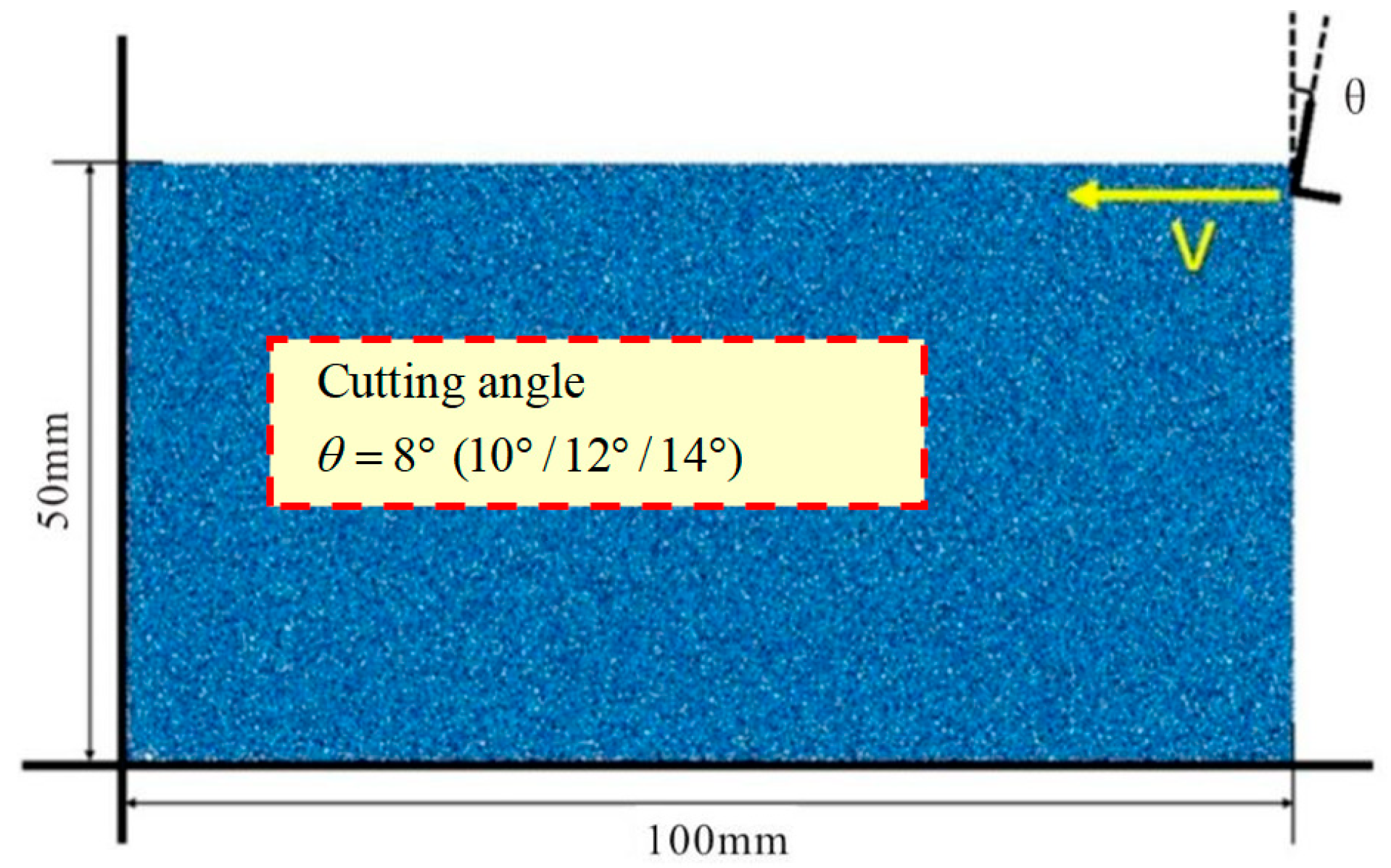
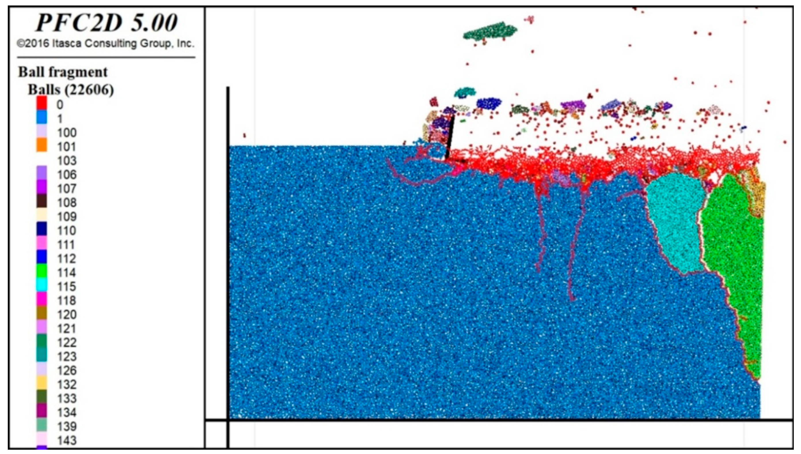
The rock cutting numerical simulation is carried out by using the particle parameters obtained by parameter calibration. The rock sample is designed as a 50 mm × 100 mm 2D granular particle and a parallel bond bonding sample. The rock cutting simulation experiment uses two cutting methods and carries out continuous loading. The design of cutting scheme is shown in Figure 3. The number of sample particles is 22,606, and the tool is cut to the left at a loading speed of 1 m/s. Four groups of rock cutting tests under different cutting angles (θ1–θ4 groups) were carried out, which were 8°, 10°, 12°, and 14°, respectively. The results are shown in Figure 2.

Figure 3.
Schematic diagram of rock cutting model.
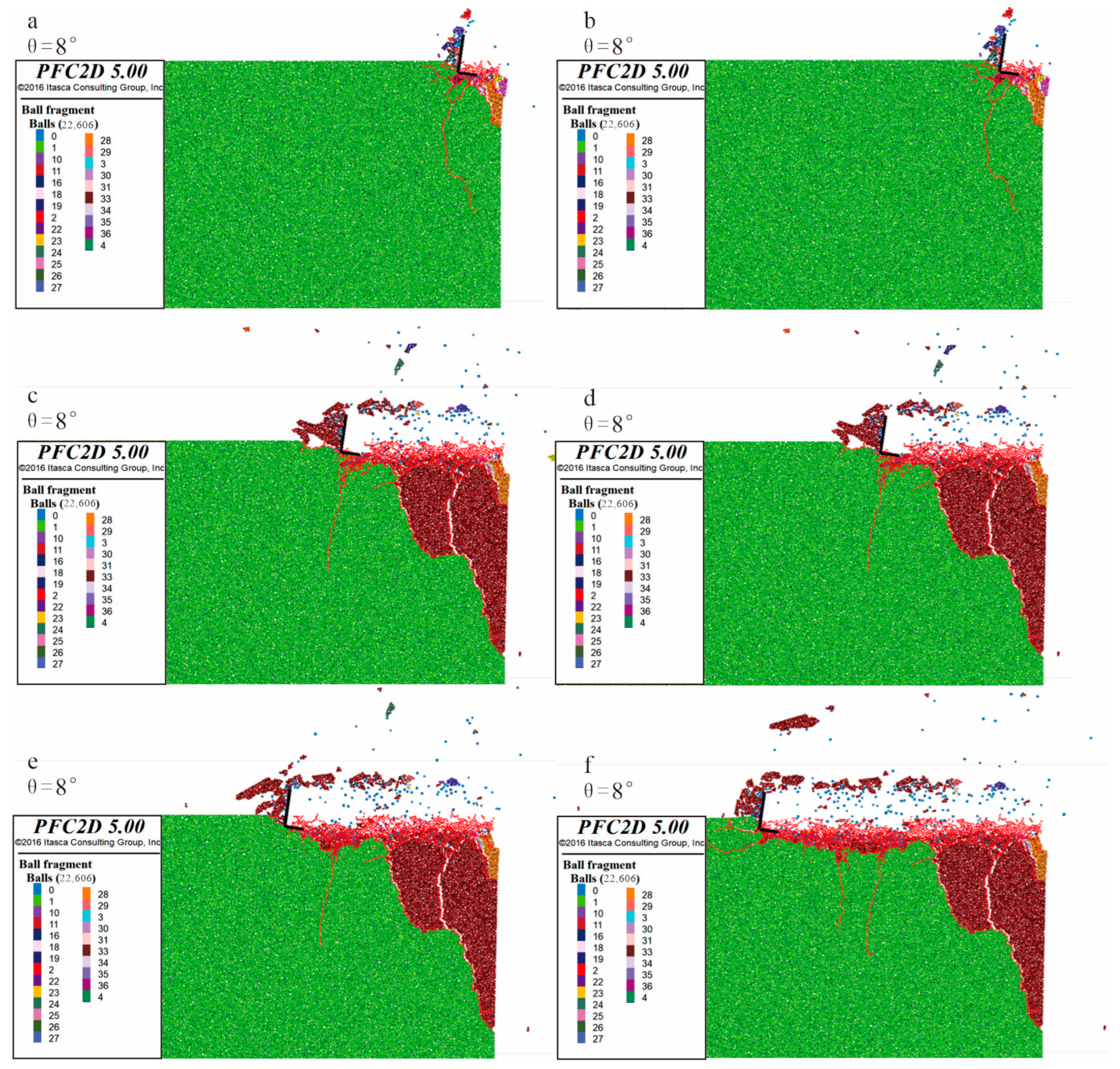
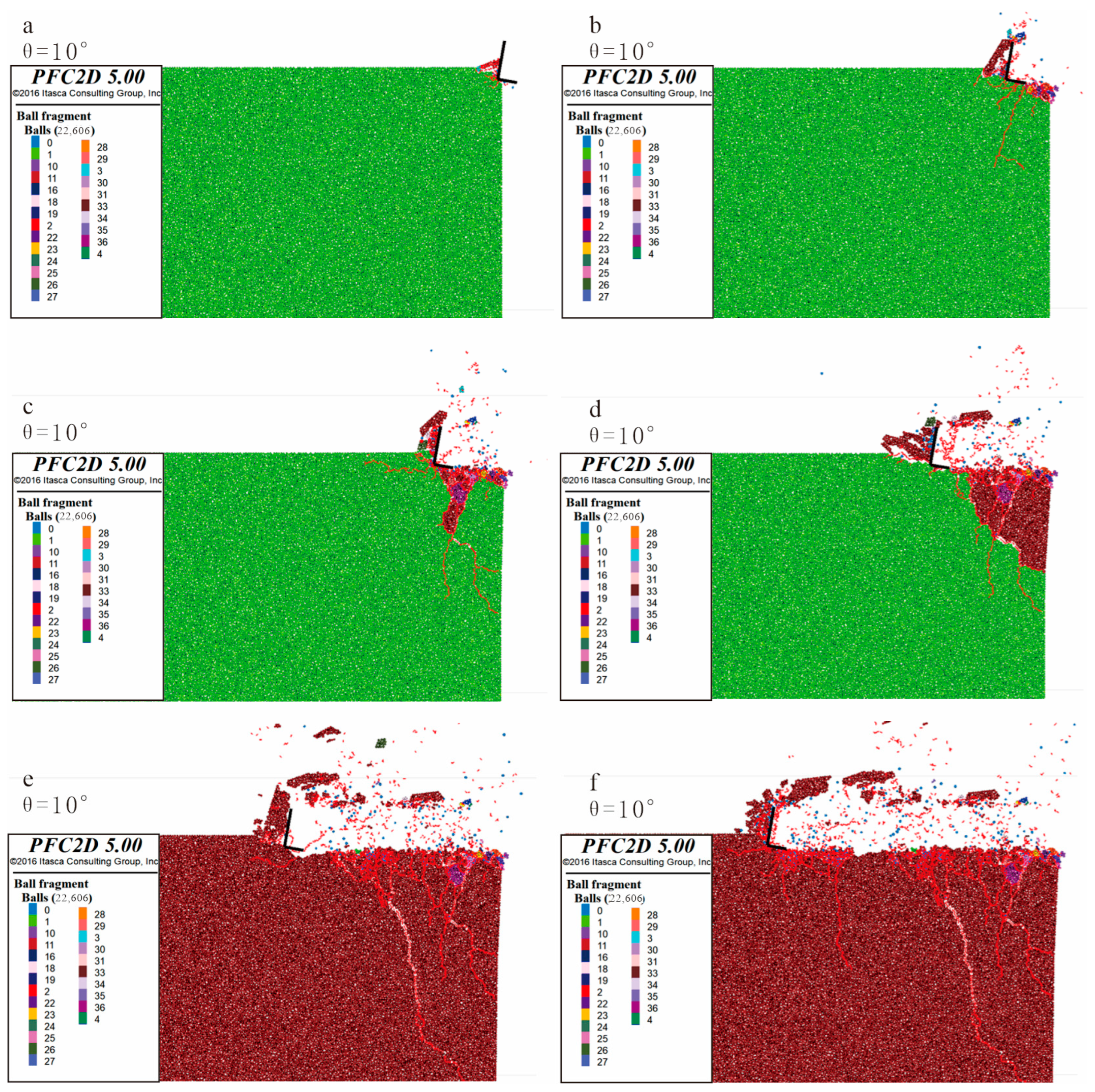
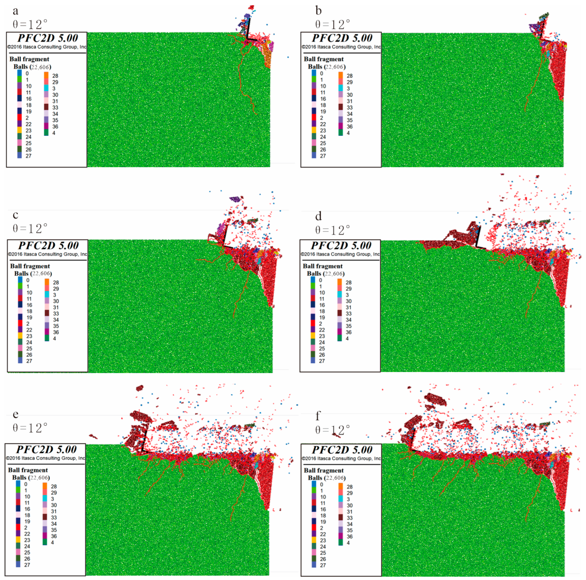
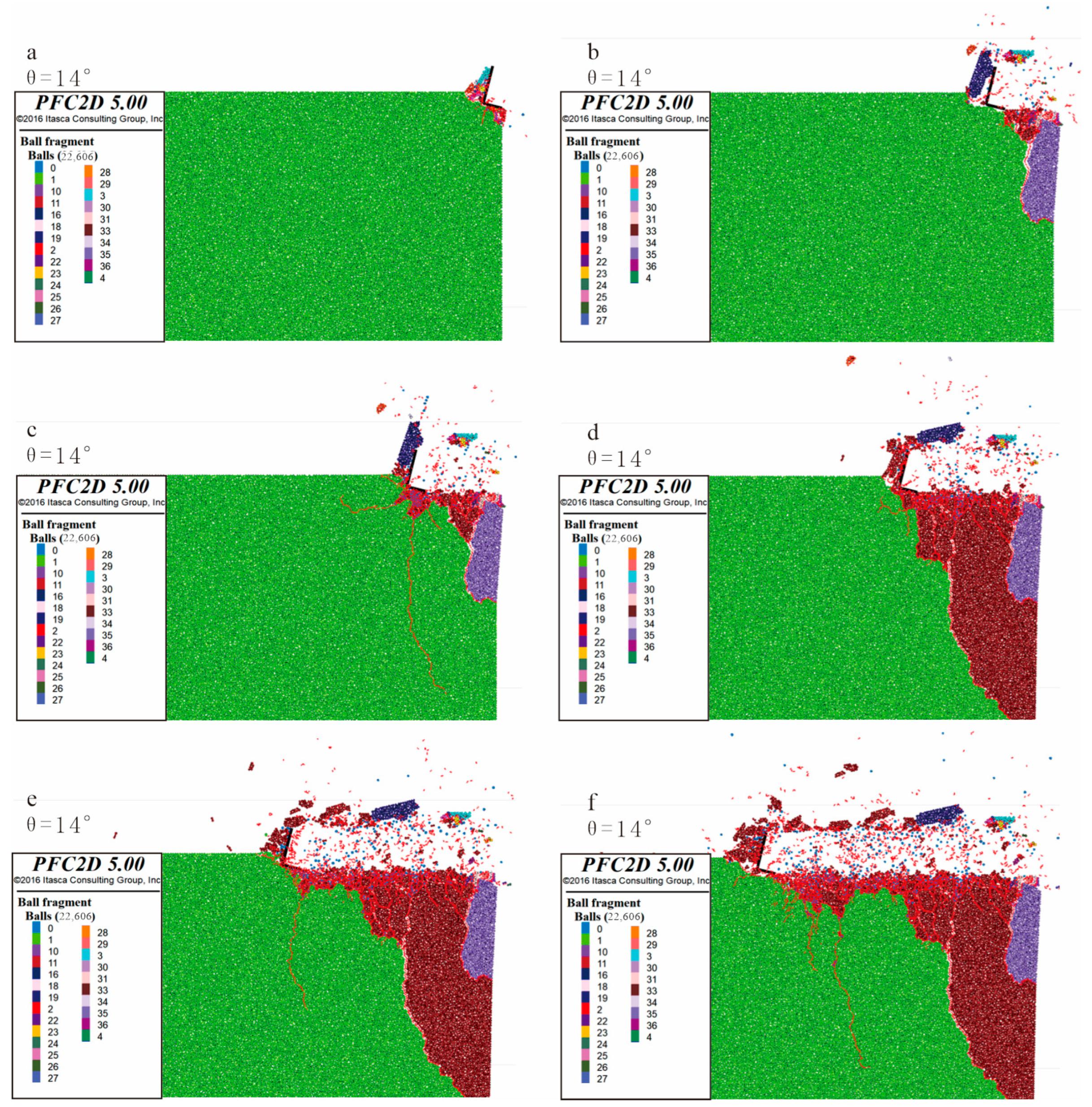
According to the simulation results (Figure 4, Figure 5, Figure 6 and Figure 7), when the cutting teeth contact with the rock, the cutting teeth will produce cutting force on the rock surface, causing elastic deformation and plastic deformation of the rock. As the cutting progresses, the stress field inside the rock changes, resulting in microscopic cracks inside the rock. These micro cracks will continue to expand with the movement of the cutting teeth and gradually develop from micro cracks to macro cracks, forming the cutting area of the cutting teeth. In the cutting area, with the increase in the number and width of cracks, more rock fragments are separated from the rock mass, forming a broken area of cutting teeth. When the crack develops to a certain extent, the cutting teeth will have a large relative displacement with the rock such that a large number of rock blocks are separated from the rock mass, forming a peeling area of the cutting teeth. These different regions correspond to different rock-breaking mechanisms of the cutting teeth, namely, cutting, compaction, shearing, and crushing, which cause different degrees of damage to the rock mass.
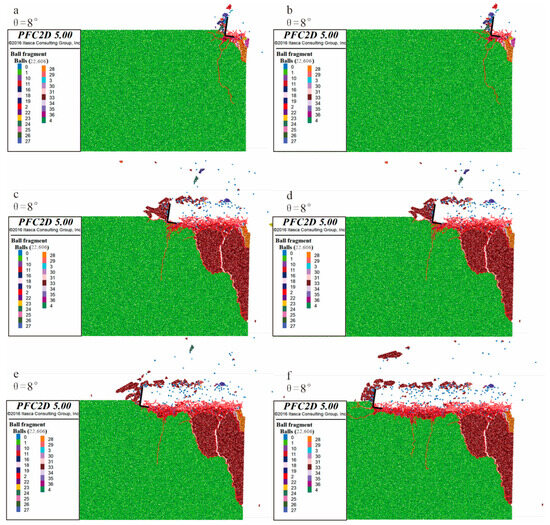
Figure 4.
Experimental group θ1. Cutting debris morphology and crack propagation diagram. Figures (a–f) are diagrams showing the morphology of cutting chips and crack propagation at different time stages during the cutting process.
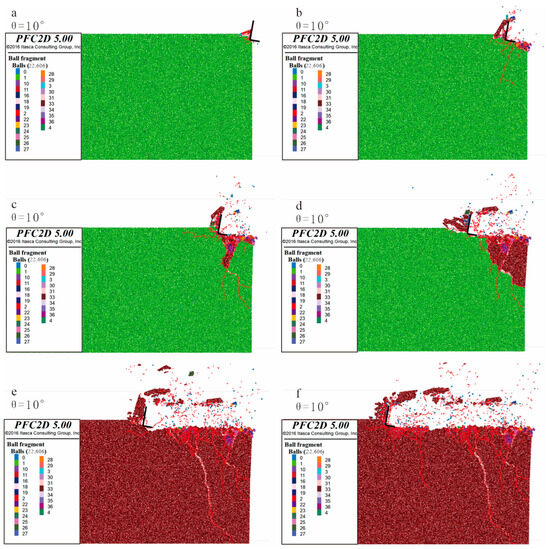
Figure 5.
Experimental group θ2. Cutting debris morphology and crack propagation diagram. Figures (a–f) are diagrams showing the morphology of cutting chips and crack propagation at different time stages during the cutting process.
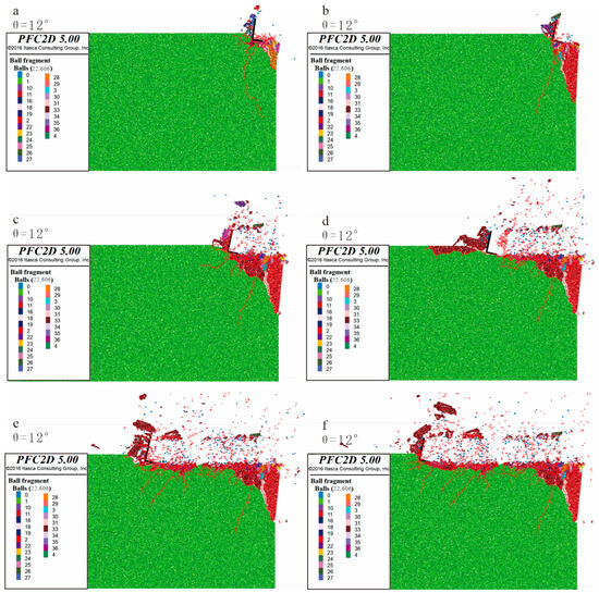
Figure 6.
Experimental group θ3. Cutting debris morphology and crack propagation diagram. Figures (a–f) are diagrams showing the morphology of cutting chips and crack propagation at different time stages during the cutting process.
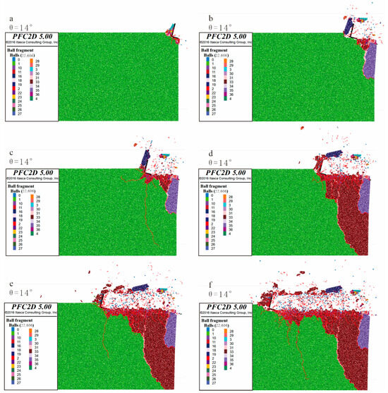
Figure 7.
Experimental group θ4. Cutting debris morphology and crack propagation diagram. Figures (a–f) are diagrams showing the morphology of cutting chips and crack propagation at different time stages during the cutting process.
When the cutting angle θ is 10°, compared with the process diagram of the cutting angle θ of 8°, it can be found that when the cutting angle θ is 10° the crack development speed and the rock fragments separated from the rock sample are greater than the crack development speed and the fragment size of the cutting angle θ of 8°—that is, a larger size of cutting is produced. Similarly, the comparison between 12° and 14° is the same. That is to say, as the cutting angle increases, the crack growth rate increases, and the rock fragments separated from the rock sample also increase.
4.3. Analysis of Rock Cutting Crack Number
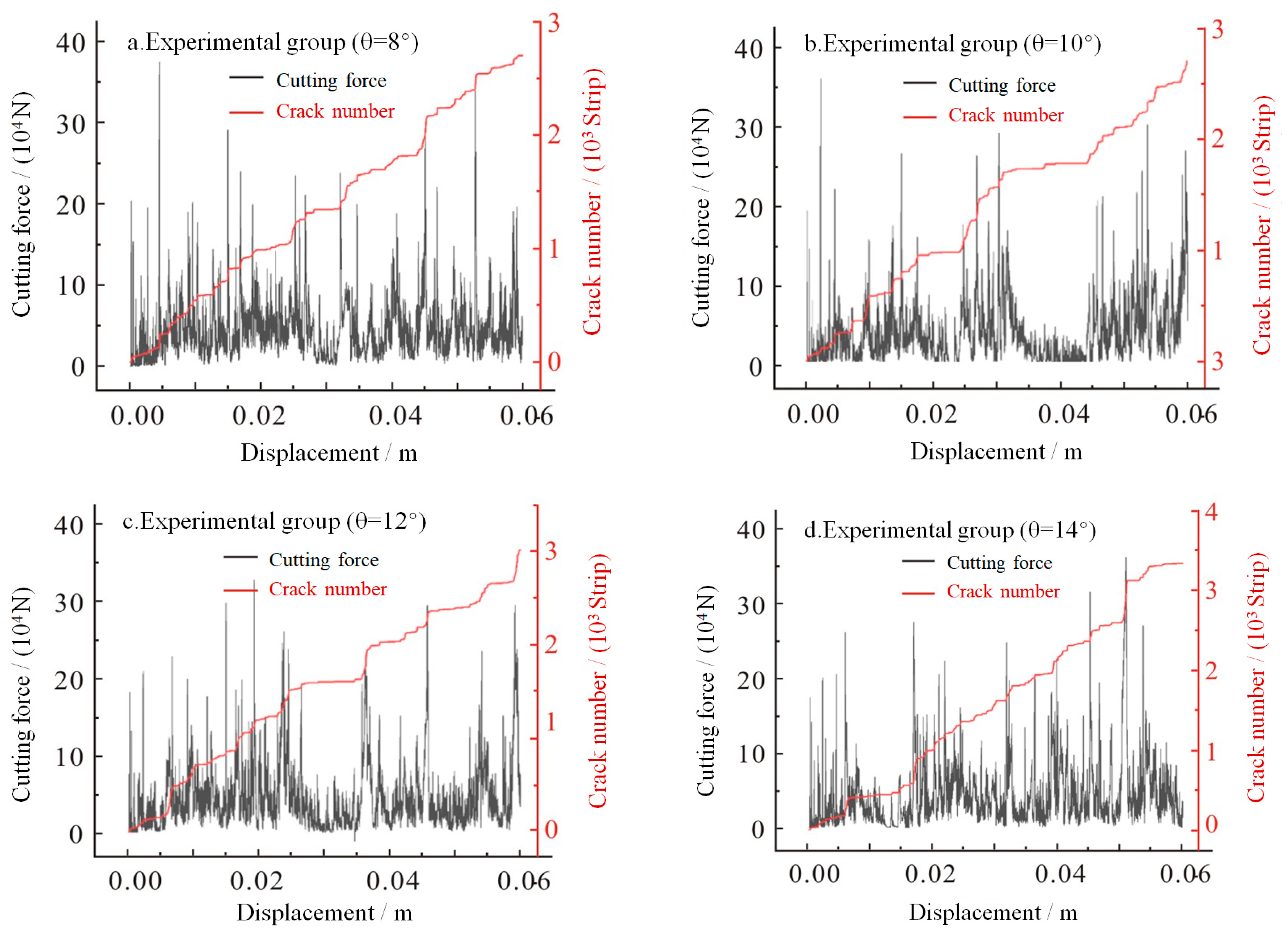
The real-time cutting force F and the number of cracks N of the four groups of cutting experiments are plotted with the change in the cutting distance X of the drilling teeth in Figure 8. From the four sets of data in Figure 8, it can be seen that the peak of the cutting force basically corresponds to the sharp increase in the number of cracks. It shows that there is a great correlation between the increase in crack number and the peak value of cutting force, which shows a periodic law. It can also be observed that there is almost no change in the number of cracks in the area where the cutting force is small and the fluctuation is slow. Combined with the morphology of the previous cutting process, it can be known that there will be large-sized cuttings at the time when the peak cutting force and the number of cracks increase sharply, and the chips are generated by large chips accompanied by small chips during the entire cutting process.
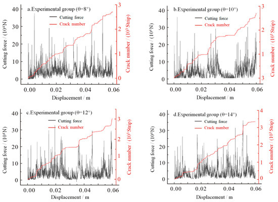
Figure 8.
Summary of four groups of cutting forces and crack numbers.
By deriving the relationship between the number of cracks and the displacement, it can be found that the number of cracks increases with the increase in the cutting angle θ. There are two ways of crack growth in the process of cutting: large step growth and small amplitude growth, which correspond to the large-sized cuttings produced by brittle failure and the small-sized cuttings produced by plastic failure, respectively. Comparing Figure 8a with Figure 8b, it can be found that the larger size of rock debris produced when the θ angle increases from 8° to 10° corresponds to the large crack step in the crack diagram. Comparing the experimental group θ2 (θ = 10°) with the experimental group θ3 (θ = 12°), it can be found that the large crack step in Figure 8c is smaller than that in Figure 8d, which is consistent with the phenomenon that less large-sized cuttings are produced when the θ angle is 12° in the cutting topography.
4.4. Rock Cutting Rock Breaking Specific Work
The rock cutting process simulated by PFC2D is different from the actual situation. In the simulation, to calculate the energy consumption generated by the loading tool, only the force load generated by the tool in contact with the rock is integrated along the loading path. For parallel cutting, since the y-direction displacement is 0, it means that there is no energy consumption in the y direction. Therefore, only the energy consumption in the x direction needs to be calculated. In this way, the energy consumption of parallel cutting can be obtained by calculating the energy consumption in the x direction (Equation (1)).
where is the energy consumed by the system in the process of rock cutting, J, and is the cutting force in the horizontal direction of the tool, N.
In PFC, with the help of the Fish language programming function, the change in contact force between particles can be tracked and monitored in real time. Once the contact force is reduced to 0, it is determined that the rock particles have peeled off from the rock matrix. These exfoliated particles were then counted to determine the total number of exfoliated particles. As shown in Figure 9, the color of the exfoliated particles is different from that of the rock matrix, and the exfoliated particles can be clearly identified and distinguished. Finally, the total volume of rock breaking V (Equation (2)) can be calculated by multiplying the total number of exfoliated particles by the volume of a single particle.
where N is the number of rock debris particles, dimensionless, and D is the average particle size, m.
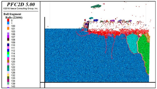
Figure 9.
Viewing the number of peeled particles.
According to the above Equation (2), the rock cutting rock breaking volume of four groups of different cutting angles is calculated as follows: , , , and .
The method of calculating the specific work of rock breaking in PFC2D is to ratio the energy of rock breaking to the volume of consumption:
where is the specific work of rock breaking under 2D condition, is the volume of rock debris, and is the energy consumed by parallel cutting.
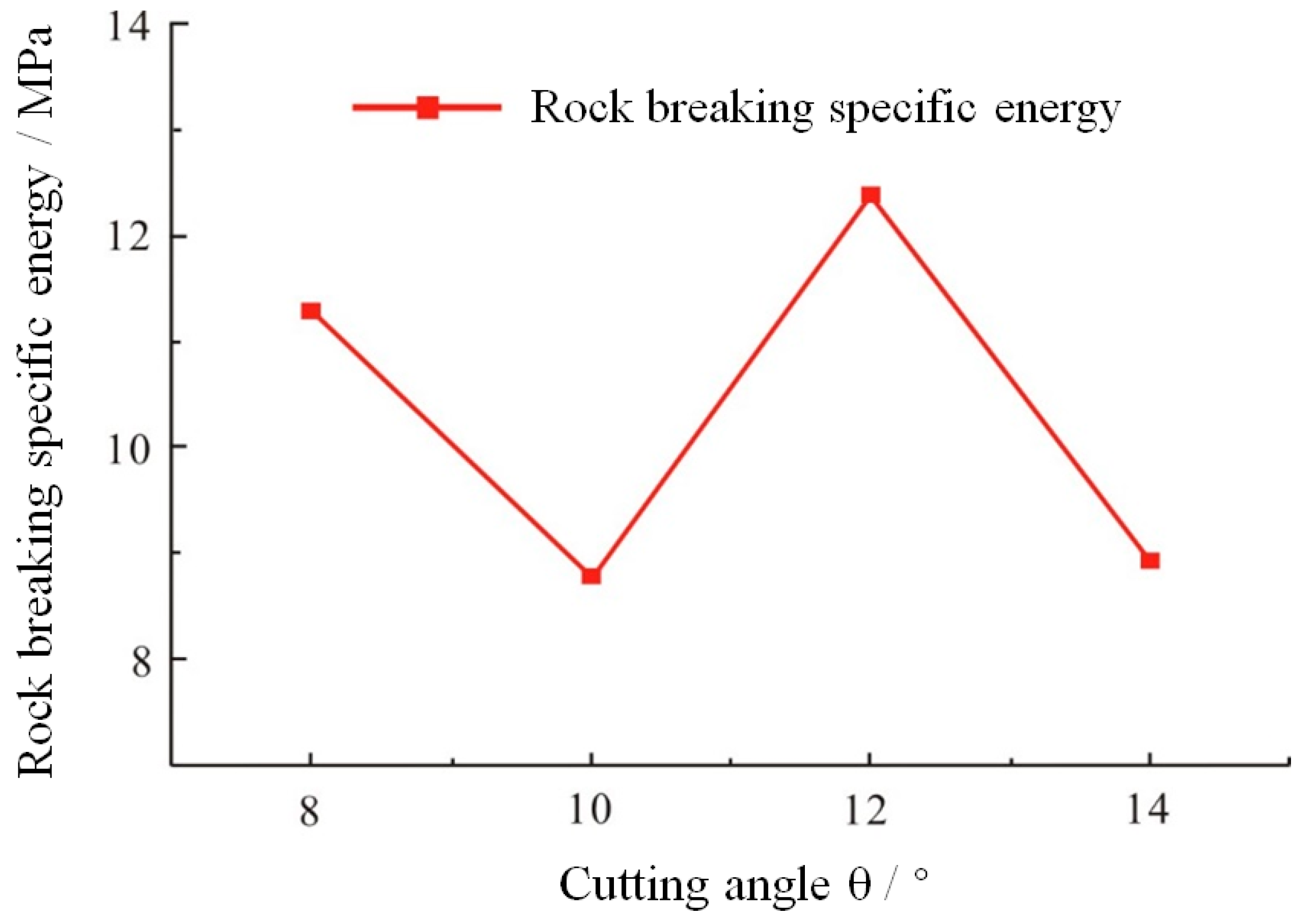
According to Equation (3), the specific work of rock cutting under four different cutting angles is calculated as follows: 11.282 MPa, 8.783 MPa, 12.386 MPa, and 8.931 MPa. It can be found from the comparison of the cutting topography that the rock-breaking specific work of the experimental group θ2 and the experimental group θ4 producing larger chips is smaller, and the rock-breaking specific work of the experimental group θ3 producing smaller chips is larger. It can be found that the larger-sized cuttings produced by brittle failure have larger rock-breaking volume and smaller rock-breaking specific work, which means that when the cutting angle θ is 10° and 14°, more cuttings can be produced and the energy required is smaller—that is, the rock-breaking efficiency is higher. When the cutting angle θ is 12°, less cuttings are produced and the efficiency is lower, as shown in Figure 10.

Figure 10.
Comparison chart of rock-breaking specific work for four groups.
In conclusion, the strata in this area are normally deposited coal measures strata, and the lithology of the strata is mainly the alternation of sandstone and mudstone without special hard rocks. Therefore, on the basis of ensuring high rock-breaking efficiency, 14° is selected as the rock-entry angle of drill bit cutting teeth suitable for the Shouyang mining area for bit arrangement optimization and the rock-breaking effect is the most ideal. The main reasons to be considered are two parts: on the one hand, in relatively soft geological layers, a larger cutting angle can enable the drill bit to cut into the stratum more quickly and improve the drilling efficiency; on the other hand, a larger cutting angle usually forms a larger chip removal space, which is conducive to discharging the broken rock cuttings. To a certain extent, this can reduce the risk of drill bit jamming or damage caused by chip blockage.
5. Engineering Practice
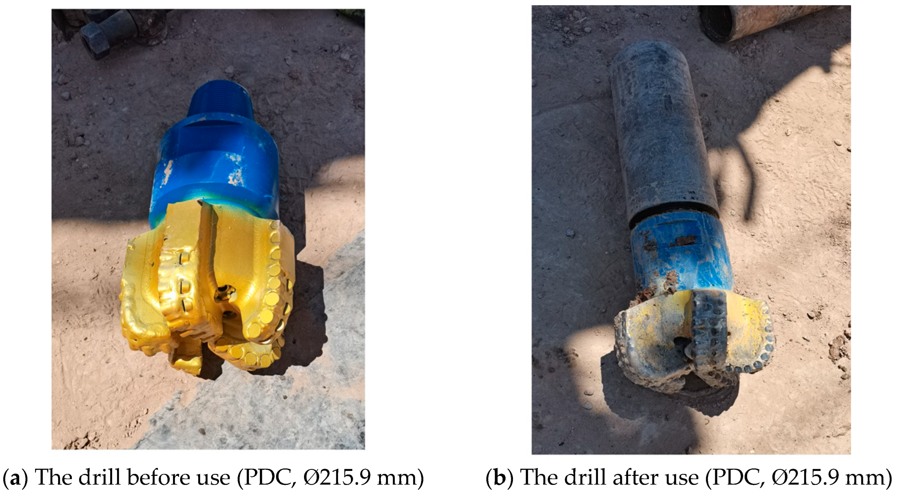
In the drilling operation of the X-154 hole of ground gas control hole in Shouyang mining area, based on the simulation analysis results of bit cutting teeth, the PDC bit was made and tested by selecting the bit cutting teeth into the rock angle of 14°. The drill assembly is a personalized PDC bit + single-bend screw drill. The drilling flushing fluid and drilling parameters are consistent with the gas control hole project completed in advance. The field verification shows that the optimized drill bit has stable performance, strong cutting ability, and good wear resistance. The maximum instantaneous penetration rate reaches 58.14 m/h and shows a slight wear state after 582 m continuous drilling in the formation, as shown in Figure 11, which is conducive to the control of hole deviation and azimuth and meets the needs of one-time drilling of life-support holes.
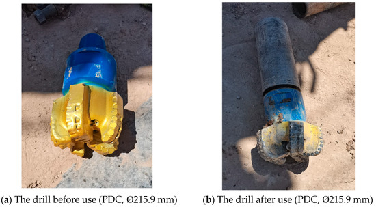
Figure 11.
Wear situation of personalized drill bits during on-site testing.
6. Conclusions
- (1)
- The Shouyang mining area is dominated by medium–fine sandstone plus mudstone and siltstone. The formation hardness is medium–soft, and the local formation is hard. The compressive strength of the bedrock formation is between 5.87 and 73.17 MPa, with an average of 33.25 MPa. The drillability grade is between 2.8 and 6.6, with an average of 5.1, and the comprehensive evaluation of drillability is good.
- (2)
- A numerical simulation of parallel cutting of rock with conical teeth was established by experimentally testing rock mechanics parameters and using the discrete element method (PFC2D). The cutting morphology, number of cutting cracks, and specific work of rock breaking at different cutting angles during the rock cutting process were studied, and it was determined that the rock-entering angles of the drill bit cutting teeth suitable for the Shouyang mining area is 14°.
- (3)
- Based on the simulation analysis results of the cutting teeth of the drill bit, the PDC bit was made with the cutting teeth of the drill bit entering the rock at an angle of 14°, and the practical application was carried out. The optimized bit has stable performance, strong cutting ability, and good wear resistance. The maximum instantaneous mechanical drilling speed reaches 58.14 m/h, and it is slightly worn after continuous drilling in the formation for 582 m, which can meet the construction requirements of the life-guarantee hole.
Author Contributions
Writing—original draft preparation, Z.Z. and J.F.; methodology, Y.K.; validation, Y.K. and B.Z.; formal analysis, Z.Z., Y.K. and J.F.; investigation, B.Z. and X.L.; conceptualization, Z.Z., J.F., Y.K., B.Z. and X.L.; supervision, Y.K. All authors have read and agreed to the published version of the manuscript.
Funding
This work was supported by the National Key Research and Development Program of China under 2023YFC3010900.
Data Availability Statement
Data are contained within the article.
Acknowledgments
We also would like to thank the anonymous reviewers for their valuable comments and suggestions that led to a substantially improved manuscript.
Conflicts of Interest
Author Zhu Zebin, Feng Jian, Kang Yuguo and Zhang Biao were employed by Beijing Dadi Hi Tech Geological Exploration Co., Ltd. Author Ling Xue was employed by School of Engineering and Technology, China University of Geosciences (Beijing). The authors declare no conflicts of interest.
References
- Zhang, B.; Kang, Y.G.; Huang, Y.; Zhang, M.; Zhou, G.; Ren, Y.; Liu, J.; Gao, K.; Zhao, Y. Key technologies of surface efficient life support hole forming for mine rescue. Coal Geol. Explor. 2022, 50, 14–23. [Google Scholar] [CrossRef]
- Kang, Y.G.; Zhang, B.; Zhang, M. Key technology and application of surface life support hole demonstration project in Meihuajing Mine. Saf. Coal Mines 2022, 53, 113–120. [Google Scholar]
- Tian, H.L.; Zou, Z.J.; Hao, S.J.; Cao, M.; Zhou, G.; Huang, Y.; Gu, H.; Wang, L. Key technologies and equipment of quickly and safely building life support and rescue channel in mine disastery. Coal Geol. Explor. 2022, 50, 2. [Google Scholar] [CrossRef]
- Zare-Reisabadi, M.R.; Kaffash, A.; Shadizadeh, S.R. Determination of optimal well trajectory during drilling and production based on borehole stability. Int. J. Rock Mech. Min. Sci. 2012, 56, 77–87. [Google Scholar] [CrossRef]
- Boukredera, F.S.; Hadjadj, A.; Youcefi, M.R. Drilling vibrations diagnostic through drilling data analyses and visualization in real time application. Earth Sci. Inform. 2021, 14, 1919–1936. [Google Scholar] [CrossRef]
- Bout, G.; Brito, D.; Gómez, R.; Carvajal, G.; Ramírez, G. Physics-Based Observers for Measurement-While-Drilling System in Down-the-Hole Drills. Mathematics 2023, 10, 4814. [Google Scholar] [CrossRef]
- He, J.-F.; Zhao, Z.-Q.; Yin, Q.-L.; Luo, Y.-J.; Gan, X. Design and optimisation on rapid rescue well-drilling technology with large-diameter pneumatic hammers. Int. J. Min. Reclam. Environ. 2019, 34, 19–33. [Google Scholar] [CrossRef]
- Dehnert, J.; Stopp, J.; Windisch, P.; Schönherrt, B. Quick-Erect Stopping System for radiation protection and mine rescue in small-scale mining. Minning Metall. Explor. 2020, 37, 1807–1817. [Google Scholar]
- Zheng, X.; Wang, H.; Guo, J.; Zhang, D. Method for multi-information drilling detection after mining disasters. Comput. Electr. Eng. 2020, 86, 106726. [Google Scholar] [CrossRef]
- Liu, L.; Zhou, J.; Kong, L.; Wang, Y.; Li, J. Analysis of the dynamic response and impact parameters of pneumatic down-the-hole hammer drilling rescue holes. Geoenergy Sci. Eng. 2023, 228, 211935. [Google Scholar] [CrossRef]
- Zhao, J.Z.; Shi, B.H. Division of coalbed methane-enriched units in the Qinshui Basin. Chin. Sci. Bull. 2005, 50, 140–145. [Google Scholar] [CrossRef]
- Wang, B.; Zhang, Q.; Qu, Z.; Zhang, Y. South Anze Structure and Its Control on Coalbed Methane Aggregation in the Qinshui Basin and the Mechanism of Syncline Gas Enrichment in the Qinshui Basin. Energies 2023, 16, 4521. [Google Scholar] [CrossRef]
- Han, X.M.; Xue, L.B.; Xu, J. Influence mechanism of polycrystalline diamond compact bit temperature rise based on thermo-fluid-solid coupling. Sci. Prog. 2023, 106, 00368504231214704. [Google Scholar] [CrossRef]
- Zhang, Z.; Zhao, D.; Zhao, Y.; Zhou, Y.; Tang, Q.; Han, J. Simulation and experimental study on temperature and stress field of full-sized PDC bits in rock breaking process. J. Pet. Sci. Eng. 2019, 186, 106679. [Google Scholar] [CrossRef]
- Gao, K.; Xu, X.; Jiao, S.; Li, Z. Modeling and experimental research on temperature field of full-sized PDC bits in rock drilling and coring. Energy Rep. 2022, 8, 8928–8938. [Google Scholar] [CrossRef]
- Wang, X.R.; Zhang, H.; Zhang, K.S. Rock breaking simulation and optimization design of multi-ridged PDC cuters. J. China Univ. Pet. 2022, 46, 63–71. [Google Scholar]
- Li, Y.C. Research status on rock-breaking mechanism and performance testing methods of PDC bit cutters. Diam. Abras. Eng. 2023, 43, 553–567. [Google Scholar] [CrossRef]
- Pang, Z.Y.; Xing, X.S.; Wu, Z.Q.; Ma, M.Y.; Mao, L.J. Experimental study on rock breaking by full-size PDC bit in heterogeneous layer. Exp. Technol. Manag. 2023, 40, 44–51. [Google Scholar] [CrossRef]
- Zhu, X.H.; Dan, Z.W. Numerical simulation of rock breaking by PDC cutters in hot dry rocks. Nat. Gas Ind. 2019, 39, 125–134. [Google Scholar]
- Cai, C.; Tan, Z.B.; Xuan, L.C.; Yang, Y.X.; Ren, H.T.; Pu, Z.C.; Zhang, P.; Xie, S. A study on drilling breakage and rock breaking mechanism by using separated impact-scraping and cutting compound bit. J. Vib. Shock 2022, 41, 232–241. [Google Scholar]
- Bazaluk, O.; Velychkovych, A.; Ropyak, L.; Pashechko, M.; Pryhorovska, T.; Lozynskyi, V. Influence of Heavy Weight Drill Pipe Material and Drill Bit Manufacturing Errors on Stress State of Steel Blades. Energies 2021, 14, 4198. [Google Scholar] [CrossRef]
- Yang, Y.; Yang, Y.X.; Ren, H.T.; Qi, Q.L.; Huang, Z.Q.; Zhou, C.X. Experimental study on motion and mechanical characteristics of the vertical wheel in the rock-breaking process. Pet. Sci. 2023, 20, 495–506. [Google Scholar] [CrossRef]
- Yu, J.P.; Zou, D.Y.; Liu, X.A.; Zhang, Y. Simulation and Experimental Study on Hybrid Bit with Different Cutters. Int. J. Simul. Model. 2021, 20, 87–98. [Google Scholar] [CrossRef]
- Niu, S.; Li, Y.; Xie, B.; Yang, Y.; Li, G.; Huang, K. Unit experimental and numerical simulation study on rock breaking mechanism of disc-like hybrid bit. Geoenergy Sci. Eng. 2023, 228, 212006. [Google Scholar] [CrossRef]
- Huang, K.L.; Ai, Z.J.; Yang, Y.X. Working characteristics research on the impacting–cutting hybrid bit. Adv. Mech. Eng. 2019, 11, 168781401985094. [Google Scholar] [CrossRef]
- Ayop, A.Z.; Bahruddin, A.Z.; Maulianda, B.; Prakasan, A.; Dovletov, S.; Atdayev, E.; Rani, A.M.A.; Elraies, K.A.; Ganat, T.A.-A.; Barati, R.; et al. Numerical modeling on drilling fluid and cutter design effect on drilling bit cutter thermal wear and breakdown. J. Pet. Explor. Prod. Tecnol. 2020, 10, 959–968. [Google Scholar] [CrossRef]
- Sun, R.J.; Ju, P.; Shi, Z.J. Simulation study of new directional drilling PDC bit used in coal mine. Geosyst. Eng. 2017, 20, 142–148. [Google Scholar] [CrossRef]
- Zhang, X.; Li, X.; Gao, K.D.; Zeng, Q.L. Analysis of Different Positional Relationships of Adjacent Double Picks on Cutting Force. Int. J. Simul. Model. 2022, 21, 651–662. [Google Scholar] [CrossRef]
- Wu, Z.B.; Yuan, Y.F.; Zhang, W.X.; Huang, J.J. Numerical simulation of rock breaking with intelligent bionic PDC Bit. Sci. Technol. Eng. 2023, 23, 6870–6880. [Google Scholar]
- Kuang, Y.C.; Zhang, M.M.; Feng, M.; Guo, C.; Zhang, Y. Simulation Model of PDC Tooth Cutting Rock and Experimental Research on the Bit. Chin. J. Undergr. Space Eng. 2018, 14, 1218–1225. [Google Scholar]
- Peng, Q.; Zhou, Y.C.; Zhou, B.; Liu, C.; Liu, Y. Development and Field Test of a Non-Planar Cutter PDC Bit with Convex Ridges. Pet. Drill. Tech. 2020, 48, 49–55. [Google Scholar]
- Tian, H.; Ren, H.; Song, D.; Yang, Y. Research on cutting track and working load of directional drilling PDC bit. J. Pet. Sci. Eng. 2021, 208, 109480. [Google Scholar] [CrossRef]
- Chen, L.; Li, D.; He, J.; Meng, L.; Chi, Q.; Li, G.; Chen, W.; Zhao, Y.; Yi, X.; Xia, C. Study on the mechanism of multidimensional cutting teeth and the influencing factors of rock breaking efficiency. PLoS ONE 2024, 19, e0297176. [Google Scholar] [CrossRef] [PubMed]
- Wang, M.; Cao, P. Calibrating the Micromechanical Parameters of the PFC2D(3D) Models Using the Improved Simulated Annealing Algorithm. Math. Probl. Eng. 2017, 2017, 6401835. [Google Scholar] [CrossRef]
- Yuan, L.-W.; Li, S.-M.; Peng, B.; Chen, Y.-M. Study on Failure Process of Tailing Dams Based on Particle Flow Theories. Int. J. Simul. Model. 2015, 14, 658–668. [Google Scholar] [CrossRef]
- Haeri, H.; Sarfarazi, V.; Marji, M.F. Static and Dynamic Response of Rock Engineering Models. Iran. J. Sci. Technol. Trans. Civ. Eng. 2021, 46, 327–341. [Google Scholar] [CrossRef]
- Yilmaz, N.G.; Yurdakul, M.; Goktan, R. Prediction of radial bit cutting force in high-strength rocks using multiple linear regression analysis. Int. J. Rock Mech. Min. Sci. 2007, 44, 962–970. [Google Scholar] [CrossRef]
- Liu, H.J.; Ling, X.; Ma, J.T. Analysis of rock breaking process of single tooth straight cutting based on PFC2D. Drill. Eng. 2023, 50, 156–162. [Google Scholar]
Disclaimer/Publisher’s Note: The statements, opinions and data contained in all publications are solely those of the individual author(s) and contributor(s) and not of MDPI and/or the editor(s). MDPI and/or the editor(s) disclaim responsibility for any injury to people or property resulting from any ideas, methods, instructions or products referred to in the content. |
© 2024 by the authors. Licensee MDPI, Basel, Switzerland. This article is an open access article distributed under the terms and conditions of the Creative Commons Attribution (CC BY) license (https://creativecommons.org/licenses/by/4.0/).