Article

Stability Characteristics of Natural Gas Hydrate Wellbores Based on Thermo-Hydro-Mech Modeling

1
State Key Laboratory of Offshore Natural Gas Hydrates, Beijing 100028, China
2
Sanya Offshore Oil & Gas Research Institute, Northeast Petroleum University, Sanya 572025, China
3
CNOOC Research Institute Ltd., Beijing 100028, China
*
Author to whom correspondence should be addressed.
Processes 2024, 12(10), 2196; https://doi.org/10.3390/pr12102196
Submission received: 9 September 2024 / Revised: 1 October 2024 / Accepted: 7 October 2024 / Published: 9 October 2024

Abstract

:
During drilling operations, drilling fluids undergo heat exchange with hydrate-bearing formations. The intrusion of drilling fluids affects hydrate stability, leading to variations in stress fields around a wellbore and complex scenarios such as borehole collapse, significantly hindering the efficient development of natural gas hydrate resources. This study establishes a thermo-hydro-mech model for hydrate-bearing inclined wells based on linear thermoelastic porous media theory and an appropriately high inhibitive drilling fluid temperature. This research reveals that drilling should follow directions of minimum horizontal stress or perpendicular to maximum horizontal stress during drilling operations to control wellbore stability. Hydrate decomposition due to factors like drilling fluid pressure and temperature can rapidly reduce the strength of low-saturation formations, significantly increasing the risk of wellbore instability. Therefore, selecting appropriate highly inhibitive and low-temperature drilling fluids during drilling operations helps control hydrate decomposition and reduce fluid intrusion, thereby mitigating risks associated with wellbore instability.

1. Introduction

Natural gas hydrates are ice-like caged crystalline compounds composed of water and natural gas under high-pressure, low-temperature conditions, in which water molecules as the primary body can capture guest gas molecules through the cavity built by hydrogen bonding [1,2,3]. They are widely distributed in deep-sea formations and are considered a highly promising new type of unconventional alternative energy because of their abundant reserves and high combustion efficiency [4,5]. This unique energy resource has attracted long-term research plans from multiple countries globally, with many incorporating it into their national key development strategies, sparking a research boom in natural gas hydrates worldwide [6]. Unlike the extraction of conventional oil and natural gas resources, natural gas hydrates are usually extracted by physicochemical means to break the original thermodynamic equilibrium state, causing solid hydrates to decompose and release natural gas. Conventional extraction methods include thermal stimulation, depressurization, and chemical injection [7,8,9], while some emerging methods include solid-state fluidization and carbon dioxide replacement [10,11].
Currently, countries such as Russia, the United States, Japan, South Korea, Canada, and China have implemented extraction plans for natural gas hydrates. For instance, in 2012, the United States successfully conducted a 30-day CO2/CH4 displacement trial in Alaska, yielding 2.8 × 10⁴ m3 of natural gas. Japan completed its initial trial extraction of gas hydrates in the Nankai Trough in 2013, validating depressurization methods, but had to halt operations because of sand production issues [12,13]. Subsequently, Japan attempted extraction again in 2017 but faced unexpected interruptions from sand production and hydrate blockage. South Korea completed the UBGH1 and UBGH2 drilling expeditions in the Ulleung Basin in 2007 and 2010, respectively, selecting suitable trial sites for future commercial extraction. India conducted the NGHP-01 and NGHP-02 expeditions in 2006 and 2015, respectively, identifying ideal sites for future hydrate trials in the Krishna–Godavari Basin (Areas B and C). China has also made significant strides in gas hydrate extraction. In 2017, China achieved its first mud-rich sandy reservoir hydrate trial using depressurization in the Shenhu area of the South China Sea, producing 3 × 10⁴ m3 of gas over 60 days. By 2020, China conducted a second trial in the Shenhu area using horizontal well depressurization technology, setting multiple world records and achieving the safe extraction of mud-rich sandy hydrates, which is crucial for commercialization [14].
However, hydrate formation requires specific low-temperature and high-pressure environments, making it highly susceptible to changes in external conditions. During drilling, factors such as frictional heating of the drill string, invasion of drilling fluids, or changes in wellbore pressure can disrupt the hydrate’s equilibrium state [15,16]. This disruption can lead to changes in reservoir geomechanical properties and cause a series of downhole safety accidents, including instability of wellbore walls and submarine landslides. These accidents not only have the potential to damage marine environments but can also delay offshore gas production operations. Therefore, maintaining wellbore stability during drilling is crucial. Currently, countries like China, Japan, Canada, and the United States are heavily investing in hydrate exploration and extraction research. However, frequent occurrences of complex situations such as wellbore collapse due to the low strength of hydrate formations, high porosity, and phase changes under thermal and pressure influences severely impact drilling efficiency [17,18].
The hydrate resources in the South China Sea are abundant, primarily existing in non-lithified forms, particularly mud-rich sandy sediments. However, after gas production from these hydrate formations, the reservoirs are highly prone to collapse. This necessitates the development of solutions to ensure the safe and efficient extraction of South China Sea hydrates, with a critical emphasis on maintaining wellbore stability [19,20].
Extensive global research has been conducted on wellbore stability during hydrate drilling [21]. Early efforts included Birchwood’s semi-analytical models for stress distribution around hydrate reservoirs during drilling, which integrated the mechanical properties of THF hydrate sediments to assess wellbore stability, albeit without accounting for the temperature effects of drilling fluids [22]. In 2007, Freij-Ayoub [23] et al. developed an evaluation model for wellbore stability under the coupled effects of thermal–flow–mechanical actions in hydrate sediment reservoirs in the Gulf of Mexico. Their model simplified the multiphase flow caused by hydrate decomposition and adopted the Mohr–Coulomb model to predict stability. Kimoto et al. proposed a mathematical model aimed at predicting subsidence due to hydrate decomposition induced by heating [24]. Their study specifically addressed submarine landslides triggered by depressurization-induced decomposition, which was observed to have a greater impact compared with heating-induced decomposition.
In the 21st century, research into wellbore stability during hydrate drilling has advanced significantly. Khurshid et al. utilized PFD-3D simulations to study changes in wellbore temperature fields during hydrate drilling processes. Their findings demonstrated that drilling fluid temperatures can disrupt the hydrated state around the wellbore, thereby increasing the risk of wellbore instability [25,26]. Qiu et al., employing MH21-HYDRES and 3D finite element geomechanical simulators, conducted studies on wellbore stability during depressurization extraction of hydrate reservoirs in the Nankai Trough, Japan. They analyzed changes in reservoir mechanical properties during extraction, providing insights into mitigating stability risks [27]. In 2011, Li et al. analyzed the impact of drilling fluid temperatures on hydrate wellbore stability in the Gulf of Mexico using the Drucker–Prager criterion. They found that lower temperatures of drilling fluids were more conducive to maintaining wellbore stability [28]. Sun et al. explored the effects of drilling fluid properties and initial reservoir conditions on wellbore stability, contributing further insights into optimizing drilling practices in hydrate formations [14]. Salehabadi et al. focused on wellbore stability post-drilling fluid intrusion and examined the causes of hydrate wellbore collapse under non-uniform loading conditions, offering crucial considerations for operational safety [29,30]. Guo et al. investigated the effects of drilling fluid properties on hydrate formations and analyzed the impact of hydrate decomposition on reservoir strength, enhancing our understanding of the complex interactions involved in hydrate drilling operations [31].
Building upon previous research, this paper introduces Euler’s transformation to account for the full stochastic nature of three-dimensional stress directions, incorporates linear thermoelastic porous media theory, and establishes a thermal–flow–solid coupled inclined wellbore stress analytical model. This approach enhances the consideration of intermediate stresses on hydrate wellbore stability using the Drucker–Prager (D-P) criterion. Additionally, this study further analyzes factors such as well inclination/azimuth, hydrate saturation, drilling fluid temperature, and reservoir porosity to assess hydrate reservoir wellbore stability comprehensively. The physical significance of the model is clearer, which provides some help to better understand the mechanism of complex dynamics influence in hydrate drilling operations.

2. Materials and Methods

2.1. Geostress Model around Gas Hydrate Wells

The stress state of gas hydrates is influenced by the in situ stress of a rock mass and its geological stress history, resulting in stochastic variations in magnitude and direction across different regions [32]. This study employs Eulerian transformations to convert between the geostress coordinate system and the borehole coordinate system, describing the stress state and stability of the gas hydrate wellbore in inclined wells. As shown in Figure 1, assuming the main stress direction in the gas hydrate reservoir is aligned with the depicted direction, the stress in the geostress coordinate system is given by
σ s = σ H σ h σ v
where σH represents maximum horizontal geostress, MPa; σh represents minimum horizontal geostress, MPa; and σv represents Overburden pressure, MPa.
Specifically, the transformation process involves rotating about the OZ1 axis by angle γ (following the right-hand rule) to obtain the coordinate system (X2, Y2, Z2), and then rotating about the OY2 axis by angle ψ to arrive at the coordinate system (x, y, z), where γ represents the azimuth angle and ψ represents the inclination angle.
In Figure 1, it is assumed that the principal stress direction in the gas hydrate formation is aligned with the direction marked in the diagram. According to the Euler transformation, the expression for transforming the geostress coordinate system to the borehole coordinate system is as follows:
M γ , ψ = cos γ cos ψ sin γ cos γ sin ψ sin γ cos ψ cos γ sin γ sin ψ sin ψ 0 cos ψ
σ x y z = σ x x σ x y σ x z σ y x σ y y σ y z σ z x σ z y σ z z = M γ , ψ σ x M γ , ψ T
where [σxyz] represents the stress tensor in the borehole coordinate system; [M(γ,ψ)] denotes the stress tensor in the geostress coordinate system; and [MT(γ,ψ)] is the transpose of [M(γ,ψ)].
To construct a relatively simple and practical stability model for gas hydrate wellbores, the following assumptions are made: (1) the gas hydrate formation is treated as a porous, elastoplastic formation, homogeneous and isotropic material, with the surrounding rock in a state of plane strain and (2) this study disregards the impact of gas or water produced from gas hydrate decomposition during drilling.
Based on these assumptions and incorporating the Euler transformation, the stress distribution equation around the gas hydrate wellbore is derived as follows:
σ r = R 2 r 2 P i + σ x x + σ y y 2 1 R 2 r 2 + σ x x σ y y 2 1 R 2 r 2 1 3 R 2 r 2 cos 2 θ α p   r p 0 σ θ = R 2 r 2 P i + σ x x + σ y y 2 1 + R 2 r 2 σ x x + σ y y 2 1 + 3 R 4 r 4 cos 2 θ α p   r p 0 σ Z = σ z z 2 ν σ x x + σ y y R 2 r 2 cos 2 θ α p   r p 0 τ r θ = σ y y σ z z 2 1 R 2 r 2 1 + 3 R 2 r 2 sin 2 θ
where σr, σθ, and σz and represent the radial, tangential, and axial stresses, respectively, at a distance r from the wellbore, in MPa; Pi is the liquid column pressure, in MPa; R is the radius of the wellbore, in meters; r is the radial distance from the well axis, in meters; θ is the azimuthal angle, in degrees; and v is the Poisson’s ratio, dimensionless.
During the drilling process, drilling fluid flows radially into the formation under a positive pressure differential, causing the internal pore structure to extend and the fluid permeation space to enlarge, resulting in changes in permeation stress based on the principles of poroelasticity [20]. The relevant expression is as follows:
σ r p = α 1 2 ν 1 ν 1 r 2 R r p f r r d r φ p   r p 0 σ θ p = α 1 2 ν 1 ν 1 r 2 R r p f r r d r + p   r p 0 φ p   r p 0 σ z p = α 1 2 ν 2 1 ν φ p   r p 0
where σrp, σθp, and σzp represent the radial, tangential, and axial stresses due to formation seepage around the wellbore, in MPa; α is the effective stress coefficient; φ is the porosity of the hydrate-bearing formation; p(r) is the real-time formation pore pressure around the hydrate wellbore, in MPa; and p0 is the initial formation pore pressure, in MPa.
During the drilling process, the heat generated by the drill bit cutting and friction of drilling tools will be transmitted to the formation through the drilling fluid, which will lead to the decomposition of hydrates, thus affecting the cementation and skeleton of the hydrate formation and causing the collapse of the wellbore wall [33]. Based on thermal elasticity theory, the expression for thermal stress around the well is as follows:
σ r T = E α T 3 1 ν 1 r 2 R r T r T 0 r d r σ θ T = E α T 3 1 ν 1 r 2 R r T r T 0 r d r + T r T 0 σ z T = E α T 3 1 ν T r T 0
where σrT, σθT, and σzT represent the radial, tangential, and axial stresses around the wellbore induced by temperature changes in the formation, in MPa; αT is the thermal expansion coefficient of the hydrate-bearing formation, in K−1; T(r) is the real-time temperature of the formation around the hydrate wellbore, in K; and To is the original temperature of the hydrate-bearing formation, in K.
By combining Equations (4)–(6), the coupled thermal–fluid–solid stress model for the inclined wellbore in hydrate formations is established as follows:
σ r = R 2 r 2 P i + σ x x + σ y y 2 1 R 2 r 2 + σ x x σ y y 2 1 R 2 r 2 1 3 R 2 r 2 cos 2 θ + δ α 1 2 ν 1 ν 1 r 2 R r p   r p 0 r d r + E α T 3 1 ν 1 r 2 R r T r T 0 r d r δ φ + α p   r p 0 σ θ = R 2 r 2 P i + σ x x + σ y y 2 1 + R 2 r 2 σ x x + σ y y 2 1 + 3 R 4 r 4 cos 2 θ + δ α 1 2 ν 1 ν 1 r 2 R r p   r p 0 r d r p   r p 0 + E α T 3 1 ν 1 r 2 R r T r T 0 r d r + T r T 0 δ φ + α p   r p 0 σ Z = σ z z 2 ν σ x x + σ y y R 2 r 2 cos 2 θ + δ α 1 2 ν 1 ν φ p   r p 0 + E α T 3 1 ν T r T 0 α p   r p 0 τ r θ = σ y y σ z z 2 1 R 2 r 2 1 + 3 R 2 r 2 sin 2 θ
According to the stress model around natural gas hydrate wells, the principal stresses at the wellbore are obtained as follows:
σ i = σ r = P i δ φ + α p   r p 0 σ j , k = σ θ + σ z 2 ± σ θ σ z 2 + 4 σ θ z 2 2
where δ is the permeability coefficient. When the wellbore is permeable, δ = 1; when the wellbore is impermeable, δ = 0. σi, σj, and σk represent the three principal stresses at the wellbore wall, in MPa.

2.2. Strength Criteria

Research by L. Vernik and others has indicated that the Mohr–Coulomb (M-C) criterion fails to predict the failure zones in wellbores accurately compared with actual observations [34,35]. Therefore, this study employs the D-P criterion to enhance the influence of intermediate stresses on the strength of gas hydrate surrounding rock. The D-P criterion not only considers the shear failure of rock but also accounts for the effects of intermediate principal stresses and static pressure, demonstrating good convergence properties and widespread use in numerical simulation software. The general expression for the D-P criterion is
J 2 R I 1 K f = 0 I 1 = σ 1 + σ 2 + σ 3 J 2 = 1 6 σ 1 σ 2 2 + σ 2 σ 3 2 + σ 1 σ 3 2 R = sin ϕ 3 3 + sin 2 ϕ K f = 3 C cos ϕ 3 3 + sin 2 ϕ
where I1 is the first stress invariant; J2 is the second deviatoric stress invariant; and R and Kf are constants related to cohesion and the internal friction angle.

2.3. Gas Hydrate Reservoir Physical Parameters

Holland et al.’s research into the microstructure of gas hydrates found that sediment deposits containing gas hydrates exhibit high permeability because natural gas exists in hydrate form within the pore space of geological formations [36]. Consequently, the actual permeability and effective porosity of geological formations are influenced by gas hydrates, expressed as follows:
φ = φ 0 1 S h
k = k 0 φ φ 0 5 × 1 φ 0 1 φ 2
where k is the effective permeability of the gas hydrate sediment, μm2; k0 is the initial permeability of the gas hydrate sediment, μm2; φ0 is the initial porosity of the gas hydrate reservoir, °; and φ is the effective porosity of the gas hydrate reservoir, °.
Before drilling into gas hydrate formations, the geological formations are in a stable state, with the pressure at each point equal to the original formation pore pressure. As drilling progresses, the gas hydrate reservoir is opened, altering the state of gas hydrates and thus changing the pore pressure of the geological formation:
p r , t = p 0 ln r R + P i ln r r + P i k ln r r ln r R + k ln r R
where r is the distance from the wellbore, m, and r is the distance from the wellbore to infinity, m.
During drilling operations, the temperature of the drilling fluid is generally higher than the temperature of the gas hydrate formation, resulting in a temperature difference between the formation and the fluid. This leads to heat exchange and changes in the temperature of the gas hydrate formation, simplified under the assumption of negligible frictional heating and infinite thermal conductivity of the casing
T r , t = T 0 ln r R + T i ln r r + T i λ ln r r ln r R + λ ln r R
where Ti is the temperature of drilling fluid, K, and λ is the thermal conductivity of formation, W/(m∙K).
The elastic modulus of gas hydrate formations varies linearly with gas hydrate saturation, as indicated by
E = E 0 + a S h
where E is the elastic modulus of gas hydrate formation, MPa, and E0 is the initial elastic modulus of gas hydrate formation, MPa.
During gas hydrate exploitation, the invasion of drilling fluid disrupts the equilibrium of the formation, causing gas hydrate decomposition and deteriorating the cohesion of the reservoir, which affects the internal friction angle. This is expressed as follows:
C = C 0 + 1 sin ϕ 2 cos ϕ a S h b
where C is cohesion after gas hydrate decomposition, MPa; C0 is the initial cohesion of the gas hydrate reservoir, MPa; ϕ is the internal friction angle, °; and a and b are material parameters, with values of 0.00191 and 1.8, respectively.
Wang et al. found that the strength and elastic modulus of sediment containing gas hydrates increase with increasing gas hydrate saturation, with a relatively minor effect on Poisson’s ratio [37]. Miyazaki et al., through triaxial experiments, discovered that the internal friction angle of gas hydrate-bearing rocks is unaffected by gas hydrate saturation [38]. Therefore, in computational processes, it is assumed that both the internal friction angle and Poisson’s ratio remain constant.

2.4. Hydrate Reservoir Petrophysical Parameters

China conducted its first natural gas hydrate drilling expedition in the northern South China Sea region in 2007, obtaining core samples and natural gas hydrate specimens from various well locations. According to drilling and logging data from this block, the hydrate reservoir is located at a water depth of 1235 m, with the mudline ranging from 185 to 229 m below the seabed. The reservoir thickness is approximately 44 m, and the porosity is around 0.4 [14]. This paper uses this block as its research background, presenting geological data and the mechanical parameters of hydrates, as shown in Table 1.

3. Results and Discussion

During the drilling process, factors such as bottom hole pressure, drilling fluid properties, hydrate characteristics, temperature, and fluid flow in formations all influence hydrate wellbore stability. Therefore, the stability of hydrate wellbores is not solely the result of individual factors but rather the outcome of the synergistic coupling of multiple factors. In analyzing this issue, it is essential to consider various factors together to achieve satisfactory results. This paper focuses only on analyzing the primary influencing factors.

3.1. Well Deviation Angle and Azimuth Angle

A well-designed wellbore trajectory can effectively reduce the risk of wellbore instability. For a given depth, selecting appropriate well deviation angles and azimuth angles is crucial for maintaining the stability of hydrate wellbores. To clarify the influence of wellbore trajectory on stress distribution around the wellbore, this paper integrates the application analysis results of the MG-C strength criterion based on hydrate strength. The equivalent collapse pressure density contour map of hydrate wellbore collapse pressure is obtained, as shown in Figure 2.
The collapse pressure contour map exhibits periodic variations within the azimuth angle range of 0° to 360°. For ease of analysis, this paper considers the azimuth angle within the range of 0° to 180°, corresponding to half a cycle. When the azimuth angle is the same, the equivalent collapse pressure density of hydrates increases with increasing well deviation angle. At a deviation angle of 90°, the collapse pressure density reaches its maximum value. Therefore, during drilling in hydrate formations, the highest risk of hydrate wellbore collapse occurs in horizontal well segments. Thus, it is crucial to maintain stability in horizontal well segments to prevent wellbore collapse. In contrast, inclined or vertical well segments are less prone to wellbore collapse.
However, research by Liu et al. indicates that the point of minimum collapse pressure density should occur outside of straight well segments and is influenced by the azimuth angle [39]. It is recommended to drill along the direction of minimum horizontal stress or perpendicular to the direction of maximum horizontal stress to reduce the risk of hydrate wellbore collapse.
To further clarify the influence of the well deviation angle and azimuth angle on the equivalent collapse pressure density of hydrate wellbores, the impact of these angles on hydrate wellbore collapse pressure density is illustrated in Figure 3. It is observed that the collapse pressure density of hydrate wellbores is independent of the azimuth angle; thus, regardless of the azimuth angle chosen, the collapse pressure density increases only with an increasing well deviation angle, and the rate of increase remains consistent.
Given that the minimum and maximum horizontal principal stresses of the hydrate formation used in this study are equal, the collapse pressure density in this formation is unaffected by the orientation of the principal stresses in the formation.
In summary, when the minimum and maximum principal stresses are equal or close, the azimuth angle does not affect the collapse pressure density of hydrates. Therefore, when designing wellbore trajectories in such formations, it is crucial to consider the influence of the well deviation angle on hydrate wellbore stability. When the minimum and maximum principal stresses are not equal or close, drilling should proceed along the direction of minimum horizontal stress or perpendicular to the direction of maximum horizontal stress. It is also essential to control the variation in the well deviation angle within a reasonable range to mitigate the risk of hydrate wellbore collapse.

3.2. Drilling Fluid Temperature

During drilling and circulation processes, drilling fluids infiltrate into formations under pressure. Simultaneously, because of temperature differences between the drilling fluid and the formation, heat exchange occurs, leading to the redistribution of the temperature field in the hydrate formation. This disturbs the equilibrium of the hydrate formation and consequently affects the stress field distribution around the hydrate wellbore. Therefore, studying the influence of drilling fluid temperature on hydrate wellbore stability is essential for enhancing safe drilling in hydrate formations.
The contour map of the equivalent collapse pressure density of hydrates under different drilling fluid temperatures is shown in Figure 4. It illustrates a positive correlation between drilling fluid temperature and the collapse pressure density of hydrate formations. As drilling fluid temperature increases, the collapse pressure density of hydrates in the same area also increases.
The current models established do not account for hydrate decomposition. In actual drilling operations, as drilling time increases and frictional heat generated during the drilling process accumulates, hydrates may become unstable and even undergo decomposition. This can weaken the hydrate’s cementing effect on the formation, further deteriorating the mechanical properties of the formation. Consequently, the unstable zone around the wellbore may expand.
The additional stresses generated under different drilling fluid temperatures are depicted in Figure 5. When the drilling fluid temperature is lower than the temperature of the hydrate formation, a tensile stress field is induced around the wellbore. This results in reduced radial and tangential stresses around the wellbore, thereby lowering the collapse pressure density of the hydrate formation.
As the distance from the wellbore decreases, the effect of temperature on the stress field around the wellbore becomes more pronounced, with the maximum tensile stress field occurring near the wellbore wall. Additionally, the vertical stress around the wellbore is independent of the distance.
Therefore, using low-temperature drilling fluids helps to enhance the stability of hydrate wellbores by reducing the collapse pressure density of the hydrate formation through the creation of a beneficial tensile stress field around the wellbore.

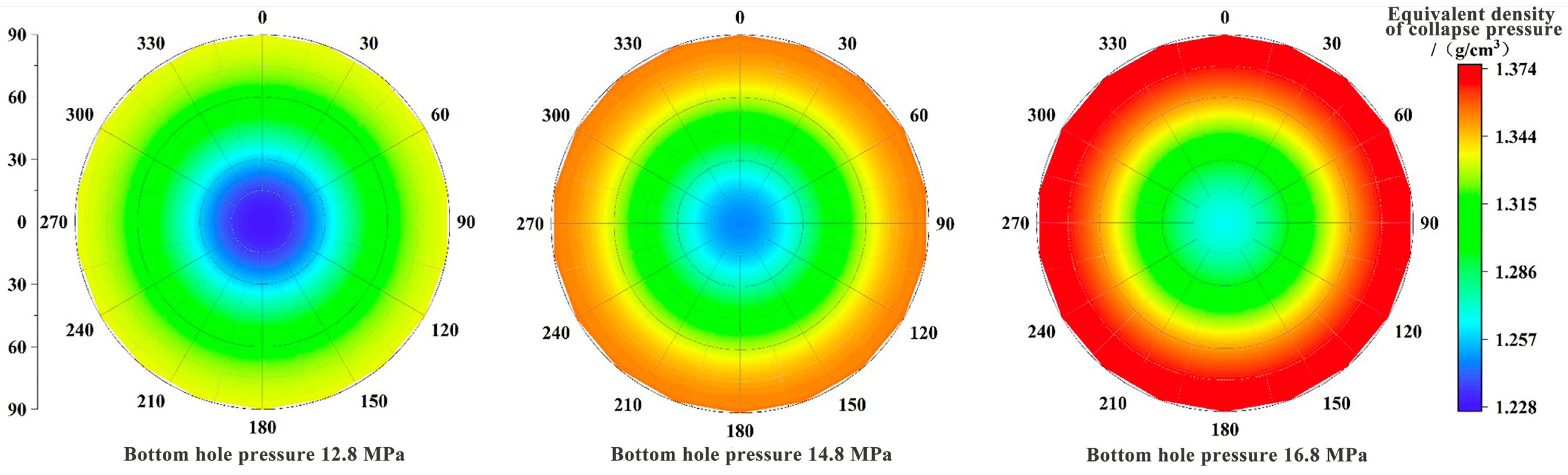
3.3. Bottom Hole Pressure

During the drilling process, an increase in bottom hole pressure leads to a greater pressure differential between the wellbore and the formation, accelerating the infiltration of drilling fluids into the formation. This affects the state of hydrates, disturbs the existing equilibrium, and increases the risk of instability in hydrate wellbores.
According to Table 1, the initial temperature of the formation is 287.15 K, equivalent to 15 °C. When the bottom hole pressure is 12.8 MPa, 14.8 MPa, and 16.8 MPa, the temperature and pressure conditions are below the hydrate phase equilibrium line, as shown in Figure 6. This indicates that the conditions do not reach the point where hydrates would decompose.
Hydrate formations are typically buried in shallow sediments beneath the seafloor. In many operational scenarios, seawater is commonly used as drilling mud. Therefore, when considering the infiltration of drilling fluids into formations under the influence of pressure differentials, the formation of a mud cake on the wellbore wall and its impact on the diffusion of drilling fluids have not been taken into account.
Figure 7 illustrates the contour map of the equivalent collapse pressure density of hydrates under different bottom hole pressures. Taking the wellbore vicinity as an example, as the bottom hole pressure increases, the collapse pressure density of hydrates also increases. This trend indicates a close relationship between bottom hole pressure and the extent of drilling fluid diffusion. Higher bottom hole pressures lead to better fluid diffusion and consequently poorer stability of hydrate wellbores.
The infiltration of drilling fluids also raises the pore pressure in the vicinity of the wellbore, which in turn counteracts the effective stress within the formation, thereby reducing the effective stress. Simultaneously, the invasion of drilling fluids may not only reduce the strength and stability of the formation but also react with hydrates within the formation, potentially causing deformation and fracturing of the formation.

3.4. Formation Porosity

During the drilling process, managed pressure drilling (MPD) is commonly used, where the hydrostatic pressure exerted by the drilling fluid exceeds the formation pore pressure. Consequently, under pressure differentials, drilling fluid pressure infiltrates into the formation, generating additional stresses that cause the redistribution of the seepage field around the hydrate wellbore. This alters the stress field distribution around the hydrate wellbore.
Based on a hydrate wellbore stress model, the equivalent collapse pressure density of hydrates was calculated for pore densities of 0.3, 0.4, and 0.5 in the hydrate formation. The contour map of collapse pressure density under different formation porosities is depicted in Figure 8. Taking the vertical well segment and its adjacent area as an example, as the pore density of the hydrate formation increases, the color deepens gradually in this region, indicating the need to increase the drilling fluid density to maintain stability.
When the formation pore density is 0.3, a drilling fluid density of approximately 1.061 g/cm3 is sufficient to maintain stability in that area. For a pore density of 0.4, the drilling fluid density needs to be increased to around 1.17 g/cm3. With a pore density of 0.5, the drilling fluid density should be about 1.24 g/cm3, and for horizontal well sections, it may even need to reach 1.350 g/cm3 to ensure stability.
The observed phenomenon is due to an increase in formation pore density, which inversely affects hydrate saturation in the formation, while the formation’s permeability also increases. As the effective porosity of the hydrate wellbore increases, it indicates the presence of more pore and fracture spaces, making it easier for drilling fluid to penetrate into the formation. This can lead to the following main issues: Increased formation pore density reduces hydrate saturation in the formation, weakening the hydrate’s cementation and support of the formation, and the higher formation pore density increases the formation’s permeability, allowing more drilling fluid to infiltrate under the same time and conditions, thereby reducing the strength of the surrounding rocks.
In summary, the increase in formation pore density reduces the strength of the hydrate formation, necessitating higher drilling fluid densities to maintain wellbore stability under similar conditions. This consequently elevates drilling risks.

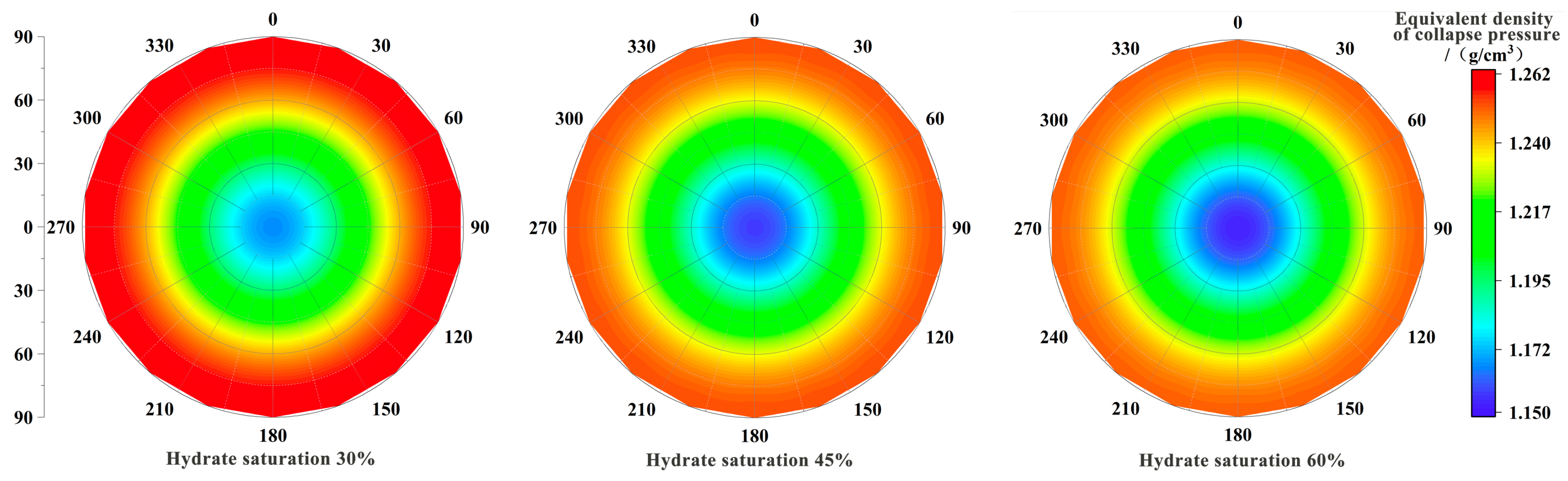
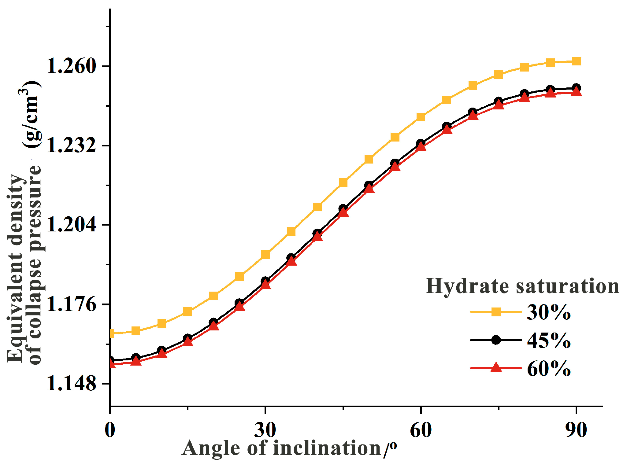
3.5. Hydrate Saturations

The saturation of hydrates is closely related to parameters such as cohesion, the elastic modulus, and other geological strength factors. This interdependence highlights the integral relationship between hydrate saturation and reservoir strength. Based on a model of stress around hydrate wells, calculations were conducted for collapse pressure equivalent density under hydrate saturations of 30%, 45%, and 60%. The corresponding collapse pressure density maps under different hydrate saturations are shown in Figure 9.
As hydrate saturation increases, the collapse pressure equivalent density decreases steadily, indicating that with higher hydrate saturation, the cohesive strength of hydrates and the elastic modulus of the reservoir increase. This signifies a continuous enhancement in the geological properties. Specifically, as hydrate saturation increases, the supportive and cementing role of hydrates in the reservoir strengthens progressively, transforming the reservoir from loose to firm.
During the transition from 45% to 60% hydrate saturation, there is minimal variation in color in the vertical well segment and adjacent areas (blue regions), suggesting little difference in collapse pressure equivalent density. However, when hydrate saturation decreases from 45% to 30%, a change of 15%, the blue areas noticeably lighten, indicating a significant increase in collapse pressure equivalent density around the hydrate wellbore.
Based on Figure 10, as the hydrate saturation increases from 30% to 45%, there is a significant decrease in the collapse pressure equivalent density of the hydrate formation. However, when the hydrate saturation increases from 45% to 60%, there is a smaller decrease in the collapse pressure equivalent density for the same increase in hydrate saturation. This trend indicates that in formations with high hydrate saturation (Sh > 60%), further increases in hydrate saturation do not significantly enhance the strength of the formation.
Specifically, under the same conditions, as the hydrate saturation increases, the mechanical properties of the hydrate formation tend towards elasticity. At the same hydrate saturation levels, an increase in effective stress (confining pressure) leads the hydrate formation towards plasticity. Therefore, the mechanical behavior of hydrate formations is more complex, which increases drilling risks. Consequently, during drilling operations, it is crucial to monitor hydrate dissociation and minimize disturbances to hydrate formations to reduce the risk of wellbore collapse.

4. Conclusions

(1)
The transformation from a wellbore coordinate system to geographical and polar coordinates via the Euler transformation facilitated the determination of principal stresses around hydrate formations. This approach integrates factors such as seepage flow, temperature distribution, and stress fields to establish a comprehensive stress model around the wellbore.
(2)
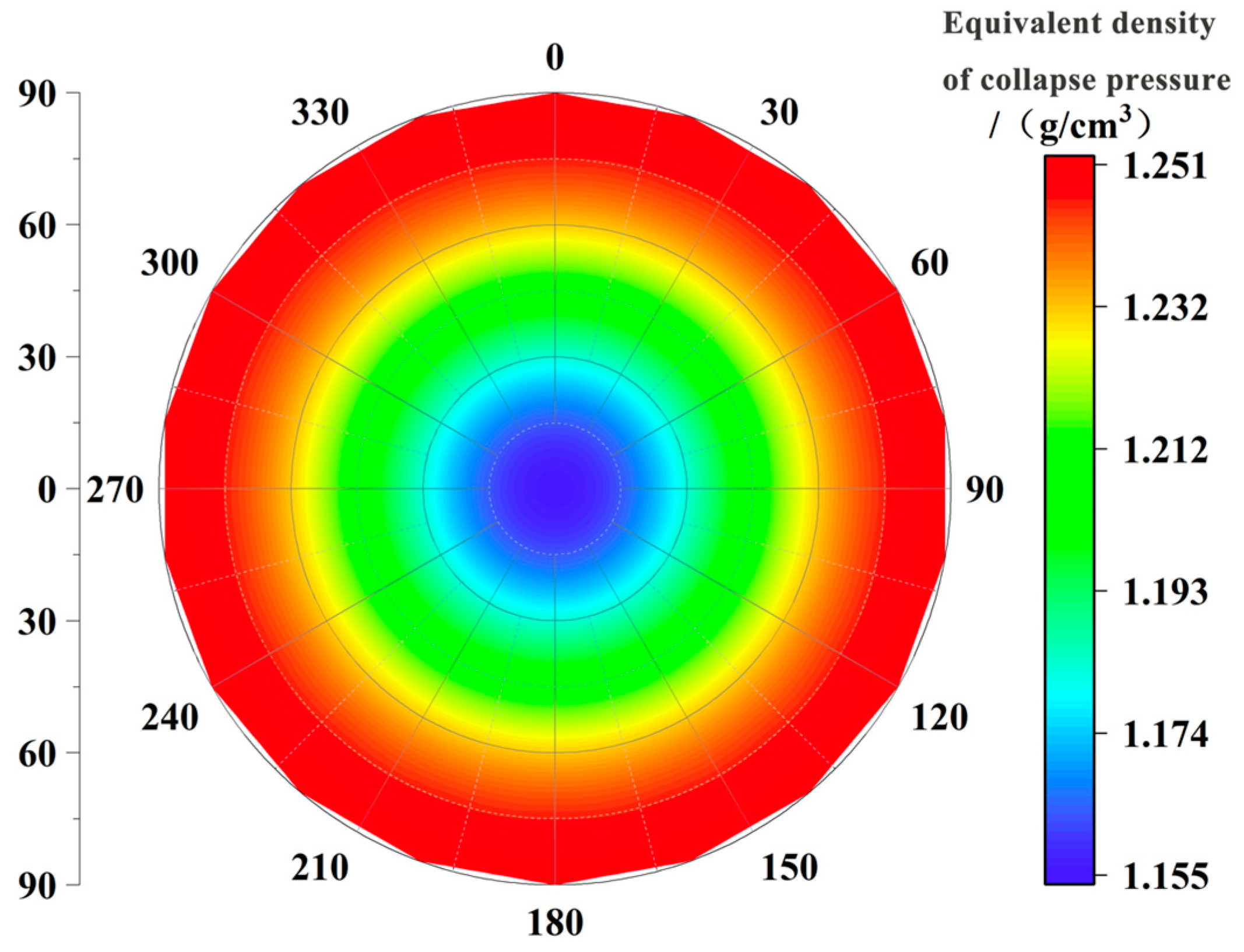
When minimum and maximum principal stresses are similar or equal, the azimuth angle has no significant impact on the collapse pressure density of hydrates. Therefore, in designing well trajectories for this formation, it is crucial to focus on the influence of the inclination angle on hydrate wellbore stability. In cases where minimum and maximum principal stresses differ, the stability of hydrate wellbores should be assessed comprehensively considering both inclination and azimuth angles. Specifically, drilling should align with the direction of minimum horizontal stress or perpendicular to the direction of maximum horizontal stress while controlling the variation in the inclination angle within reasonable limits to mitigate the risk of hydrate wellbore collapse.
(3)
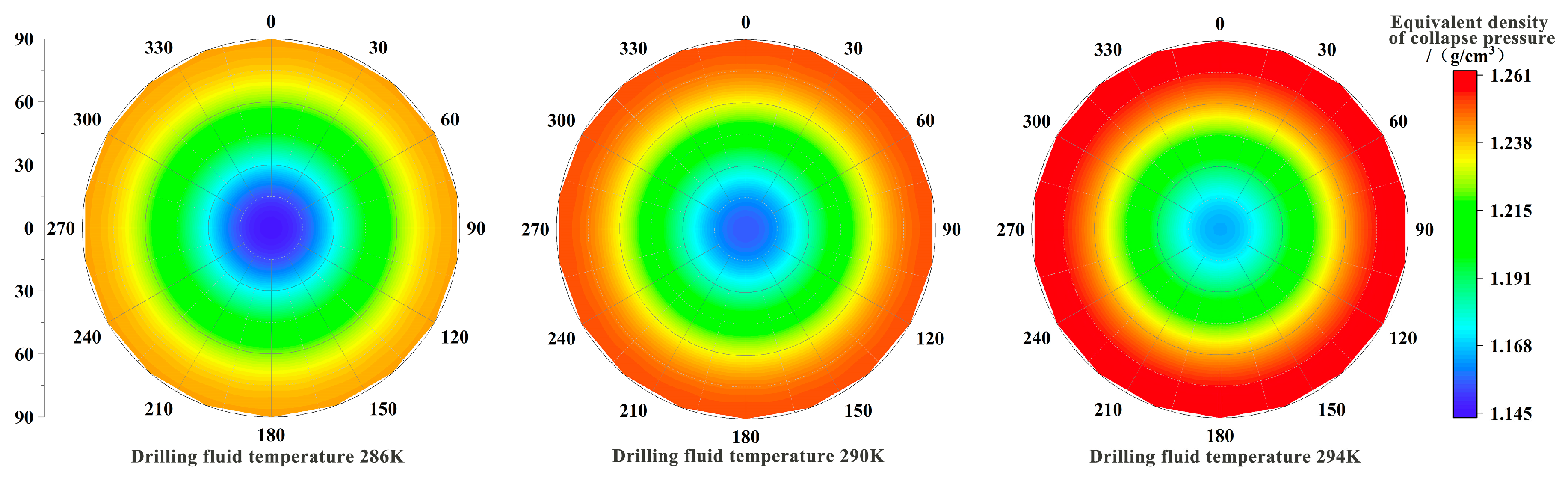
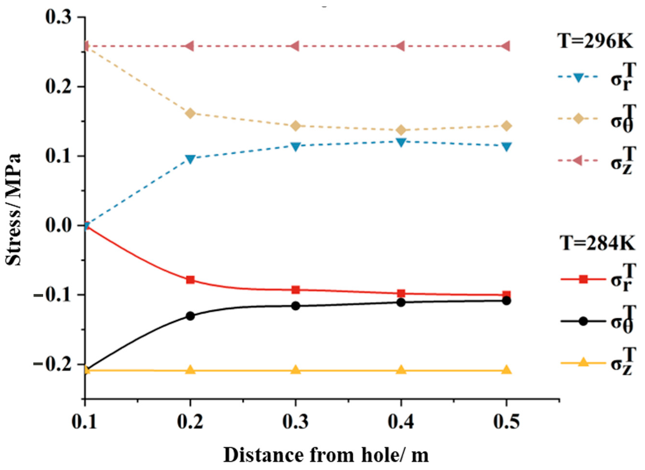
High-temperature drilling fluids induce thermal stresses in hydrate formations, disrupting stress equilibrium around the wellbore and perturbing hydrate states, thereby increasing the risk of hydrate wellbore instability. Therefore, during drilling operations in hydrate formations, it is advisable to use low-temperature drilling fluids, ideally maintaining drilling fluid temperatures below or at least not exceeding the temperatures of the hydrate formation. This approach not only reduces the risk of hydrate dissociation but also enhances the stability of hydrate formations.
(4)
The invasion of drilling fluids can diminish the strength and stability of formations and may react with hydrates within the formation, altering the structure of the formation. This alteration can lead to deformation and fracturing of the formation, posing challenges to wellbore stability. Hence, monitoring changes in bottom hole pressure during drilling is crucial to mitigate damage caused by drilling fluid invasion into hydrate wellbores. The size of formation porosity directly affects hydrate saturation, where higher porosity implies lower hydrate saturation and weaker formation strength. Conversely, lower porosity makes the invasion of drilling fluids more challenging, thereby increasing drilling risks. During the process of hydrate decomposition from high to low saturation, formation strength decreases gradually initially but rapidly later. Therefore, vigilance towards hydrate dissociation during drilling is essential to minimize disturbances to hydrate formations and reduce the risk of wellbore collapse.

Author Contributions

Methodology, S.S.; validation, X.Z.; writing—original draft, X.Z.; writing—review and editing, Y.Z. All authors have read and agreed to the published version of the manuscript.

Funding

This research was funded by the Open-ended Fund of State Key Laboratory of National Gas Hydrates, grant number 2022-FKJJ-SHW.

Data Availability Statement

The original contributions presented in this study are included in the article. Further inquiries can be directed to the corresponding author.

Conflicts of Interest

Zhang Xiaohan and Zhou Yunjianare were employed by the CNOOC Research Institute Co., Ltd. The authors declare that this research was conducted in the absence of any commercial or financial relationships that could be construed as a potential conflict of interest.

References

  1. Xu, C.; Li, X.; Yan, K.; Ruan, X.; Chen, Z.; Xia, Z. Research Progress in Hydrate-Based Technologies and Processes in China: A Review. Chin. J. Chem. Eng. 2019, 27, 1998–2013. [Google Scholar] [CrossRef]
  2. Sun, X.; Yao, D.; Qu, J.; Sun, S.; Qin, Z.; Tao, L.; Zhao, Y. A Novel Transient Hole Cleaning Algorithm for Horizontal Wells Based on Drift-Flux Model. Geoenergy Sci. Eng. 2024, 233, 212517. [Google Scholar] [CrossRef]
  3. Giovannetti, R.; Gambelli, A.M.; Castellani, B.; Rossi, A.; Minicucci, M.; Zannotti, M.; Li, Y.; Rossi, F. May Sediments Affect the Inhibiting Properties of NaCl on CH4 and CO2 Hydrates Formation? An Experimental Report. J. Mol. Liq. 2022, 359, 119300. [Google Scholar] [CrossRef]
  4. Liu, L.; Sun, Z.; Zhang, L.; Wu, N.; Yichao, Q.; Jiang, Z.; Geng, W.; Cao, H.; Zhang, X.; Zhai, B.; et al. Progress in Global Gas Hydrate Development and Production as a New Energy Resource. Acta Geol. Sin. 2019, 93, 731–755. [Google Scholar] [CrossRef]
  5. Feng, J.; Yan, T.; Hou, Z. Numerical Simulation Study of Factors Influencing Ultrasonic Cavitation Bubble Evolution on Rock Surfaces during Ultrasonic-Assisted Rock Breaking. Water 2024, 16, 2234. [Google Scholar] [CrossRef]
  6. Li, G.; Li, X.S.; Lv, Q.N.; Xiao, C.W.; Deng, F.C. Long-Term Analysis of the 2020 Gas Hydrate Production Test in the South China Sea by Full Implicit Simulator of Hydrate. Energy Fuels 2023, 37, 3785–3798. [Google Scholar] [CrossRef]
  7. Zhong, X.; Pan, D.; Zhai, L.; Zhu, Y.; Zhang, H.; Zhang, Y.; Wang, Y.; Li, X.; Chen, C. Evaluation of the Gas Production Enhancement Effect of Hydraulic Fracturing on Combining Depressurization with Thermal Stimulation from Challenging Ocean Hydrate Reservoirs. J. Nat. Gas Sci. Eng. 2020, 83, 103621. [Google Scholar] [CrossRef]
  8. Kim, H.C.; Bishnoi, P.R.; Heidemann, R.A.; Rizvi, S.S.H. Kinetics of Methane Hydrate Decomposition. Chem. Eng. Sci. 1987, 42, 1645–1653. [Google Scholar] [CrossRef]
  9. Yousif, M.H.; Li, P.M.; Selim, M.S.; Sloan, E.D. Depressurization of Natural Gas Hydrates in Berea Sandstone Cores. J. Incl. Phenom. Mol. Recognit. Chem. 1990, 8, 71–88. [Google Scholar] [CrossRef]
  10. Zhou, S.; Li, Q.; Wei, C.; Zhou, J.; Pang, W.; Yufa, H.; Xin, L.; Xu, L.; Qiang, F.; Jiang, L. The World’s First Successful Implementation of Solid Fluidization Well Testing and Production for Non-Diagenetic Natural Gas Hydrate Buried in Shallow Layer in Deep Water. In Proceedings of the Offshore Technology Conference, Houston, TX, USA, 30 April–3 May 2018; Volume 4, pp. 2784–2794. [Google Scholar] [CrossRef]
  11. Koh, D.Y.; Kang, H.; Lee, J.W.; Park, Y.; Kim, S.J.; Lee, J.; Lee, J.Y.; Lee, H. Energy-Efficient Natural Gas Hydrate Production Using Gas Exchange. Appl. Energy 2016, 162, 114–130. [Google Scholar] [CrossRef]
  12. Li, J.; Zhang, Y.; Di, S.; Lin, L.; Zhou, Y. Research on hydrate-bearing reservoir deformation and wellbore wall stability during natural gas hydrate exploitation. Geomech. Energy Environ. 2023, 34, 100458. [Google Scholar] [CrossRef]
  13. Wang, L.; Li, Y.; Shen, S.; Liu, W.; Sun, X.; Liu, Y.; Zhao, J. Mechanical Behaviours of Gas-Hydrate-Bearing Clayey Sediments of the South China Sea. Environ. Geotech. 2022, 9, 210–222. [Google Scholar] [CrossRef]
  14. Sun, J.; Ning, F.; Lei, H.; Gai, X.; Sánchez, M.; Lu, J.; Li, Y.; Liu, L.; Liu, C.; Wu, N.; et al. Wellbore Stability Analysis during Drilling through Marine Gas Hydrate-Bearing Sediments in Shenhu Area: A Case Study. J. Pet. Sci. Eng. 2018, 170, 345–367. [Google Scholar] [CrossRef]
  15. Kurihara, M.; Sato, A.; Funatsu, K.; Ouchi, H.; Yamamoto, K.; Numasawa, M.; Ebinuma, T.; Narita, H.; Masuda, Y.; Dallimore, S.R.; et al. Analysis of Production Data for 2007/2008 Mallik Gas Hydrate Production Tests in Canada. In Proceedings of the International Oil and Gas Conference and Exhibition in China, Beijing, China, 8–10 June 2010; Volume 4, pp. 2908–2931. [Google Scholar] [CrossRef]
  16. Dong, L.; Liao, H.; Li, Y.; Meng, Q.; Hu, G.; Wang, J.; Wu, N. Analysis of the Mechanical Properties of the Reconstituted Hydrate-Bearing Clayey-Silt Samples from the South China Sea. J. Mar. Sci. Eng. 2022, 10, 831. [Google Scholar] [CrossRef]
  17. Dong, L.; Wu, N.; Leonenko, Y.; Wan, Y.; Liao, H.; Hu, G.; Li, Y. A coupled thermal-hydraulic-mechanical model for drilling fluid invasion into hydrate-bearing sediments. Energy 2023, 278, 127785. [Google Scholar] [CrossRef]
  18. Ma, T.; Chen, P.; Yang, C.; Zhao, J. Wellbore Stability Analysis and Well Path Optimization Based on the Breakout Width Model and Mogi-Coulomb Criterion. J. Pet. Sci. Eng. 2015, 135, 678–701. [Google Scholar] [CrossRef]
  19. Al-Ajmi, A.M.; Zimmerman, R.W. A New Well Path Optimization Model for Increased Mechanical Borehole Stability. J. Pet. Sci. Eng. 2009, 69, 53–62. [Google Scholar] [CrossRef]
  20. Cheng, W.; Ning, F.; Sun, J.; Liu, Z.; Jiang, G.; Li, X. A Porothermoelastic Wellbore Stability Model for Riserless Drilling through Gas Hydrate-Bearing Sediments in the Shenhu Area of the South China Sea. J. Nat. Gas Sci. Eng. 2019, 72, 103036. [Google Scholar] [CrossRef]
  21. Ghassemi, A.; Tao, Q.; Diek, A. Influence of Coupled Chemo-Poro-Thermoelastic Processes on Pore Pressure and Stress Distributions around a Wellbore in Swelling Shale. J. Pet. Sci. Eng. 2009, 67, 57–64. [Google Scholar] [CrossRef]
  22. Birchwood, R.; Noeth, S.; Hooyman, P.; Winters, W.; Jones, E. Wellbore stability model for marine sediments containing gas hydrates. In Proceedings of the AADE National Conference and Exhibition, Houston, TX, USA, 5–7 April 2005. [Google Scholar]
  23. Freij-Ayoub, R.; Tan, C.; Clennell, B.; Tohidi, B.; Yang, J. A Wellbore Stability Model for Hydrate Bearing Sediments. J. Pet. Sci. Eng. 2007, 57, 209–220. [Google Scholar] [CrossRef]
  24. Kimoto, S.; Oka, F.; Fushita, T.; Fujiwaki, M. A Chemo-Thermo-Mechanically Coupled Numerical Simulation of the Subsurface Ground Deformations Due to Methane Hydrate Dissociation. Comput. Geotech. 2007, 34, 216–228. [Google Scholar] [CrossRef]
  25. Chen, Y.; Sun, T.; Zhang, Y.; Chen, Y.; Sun, T.; Zhang, Y.; Qu, X.; Shi, H.; Ying, H. The Suitable Strength Criterion to Determine the Collapse of Hydrate Reservoirs with Different Saturation. In Proceedings of the ISOPE International Ocean and Polar Engineering Conference, Honolulu, HI, USA, 16–21 June 2019. [Google Scholar]
  26. Khurshid, I.; Lee, K.J.; Bank, J.J.; Choe, J. Heat Transfer and Well Bore Stability Analysis in Hydrate Bearing Zone in the East Sea, South Korea. In Proceedings of the Offshore Technology Conference, Houston, TX, USA, 3–6 May 2010; Volume 2, pp. 1115–1131. [Google Scholar] [CrossRef]
  27. Qiu, K.; Yamamoto, K.; Birchwood, R.; Chen, Y. Well Integrity Evaluation for Methane Hydrate Production in the Deepwater Nankai Trough. In Proceedings of the International Petroleum Technology Conference, Doha, Qatar, 19–22 January 2014; Volume 1, pp. 822–846. [Google Scholar] [CrossRef]
  28. Li, L.; Cheng, Y.; Zhang, Y.; Cui, Q.; Zhao, F. A Fluid-Solid Coupling Model of Wellbore Stability for Hydrate Bearing Sediments. Procedia Eng. 2011, 18, 363–368. [Google Scholar] [CrossRef]
  29. Salehabadi, M.; Jin, M.; Yang, J.; Haghighi, H.; Ahmed, R.; Tohidi, B. Finite Element Modeling of Casing in Gas-Hydrate-Bearing Sediments. SPE Drill. Complet. 2009, 24, 545–552. [Google Scholar] [CrossRef]
  30. Salehabadi, M.; Jin, M.; Yang, J.; Ahmed, R.; Tohidi, B. The Effect of Casing Eccentricity on the Casing Stability Analysis of a Wellbore Drilled in Gas Hydrate Bearing Sediments. In Proceedings of the SPE EUROPEC/EAGE Annual Conference and Exhibition, Barcelona, Spain, 14–17 June 2010; Volume 3, pp. 2189–2204. [Google Scholar] [CrossRef]
  31. Guo, Z.Y.; Wang, H.N.; Jiang, M.J. Elastoplastic Analytical Investigation of Wellbore Stability for Drilling in Methane Hydrate-Bearing Sediments. J. Nat. Gas Sci. Eng. 2020, 79, 103344. [Google Scholar] [CrossRef]
  32. Sun, J.; Ning, F.; Liu, T.; Li, Y.; Lei, H.; Zhang, L.; Cheng, W.; Wang, R.; Cao, X.; Jiang, G. Numerical Analysis of Horizontal Wellbore State during Drilling at the First Offshore Hydrate Production Test Site in Shenhu Area of the South China Sea. Ocean. Eng. 2021, 238, 109614. [Google Scholar] [CrossRef]
  33. Gao, Y.; Sun, B.; Xu, B.; Wu, X.; Chen, Y.; Zhao, X.; Chen, L. A Wellbore/Formation-Coupled Heat-Transfer Model in Deepwater Drilling and Its Application in the Prediction of Hydrate-Reservoir Dissociation. SPE J. 2017, 22, 756–766. [Google Scholar] [CrossRef]
  34. Vernik, L.; Zoback, M.D. Estimation of Maximum Horizontal Principal Stress Magnitude from Stress-Induced Well Bore Breakouts in the Cajon Pass Scientific Research Borehole. J. Geophys. Res. Solid Earth 1992, 97, 5109–5119. [Google Scholar] [CrossRef]
  35. Späth, M.; Herrmann, C.; Prajapati, N.; Schneider, D.; Schwab, F.; Selzer, M.; Nestler, B. Multiphase-Field Modelling of Crack Propagation in Geological Materials and Porous Media with Drucker-Prager Plasticity. Comput. Geosci. 2021, 25, 325–343. [Google Scholar] [CrossRef]
  36. Holland, G.P.; Jenkins, J.E.; Creager, M.S.; Lewis, R.V.; Yarger, J.L. Solid-State NMR Investigation of Major and Minor Ampullate Spider Silk in the Native and Hydrated States. Biomacromolecules 2008, 9, 651–657. [Google Scholar] [CrossRef]
  37. Wang, H.N.; Chen, X.P.; Jiang, M.J.; Guo, Z.Y. Analytical Investigation of Wellbore Stability during Drilling in Marine Methane Hydrate-Bearing Sediments. J. Nat. Gas Sci. Eng. 2019, 68, 102885. [Google Scholar] [CrossRef]
  38. Miyazaki, K.; Tenma, N.; Aoki, K.; Sakamoto, Y.; Yamaguchi, T. Effects of confining pressure on mechanical properties of artificial methane-hydrate-bearing sediment in triaxial compression test. Int. J. Offshore Polar Eng. 2011, 21, 148–154. [Google Scholar]
  39. Liu, M.; Jin, Y.; Lu, Y.; Chen, M.; Hou, B.; Chen, W.; Wen, X.; Yu, X. A Wellbore Stability Model for a Deviated Well in a Transversely Isotropic Formation Considering Poroelastic Effects. Rock Mech. Rock Eng. 2016, 49, 3671–3686. [Google Scholar] [CrossRef]
Figure 1. Schematic representation of the conversion between the geostress coordinate system and borehole coordinates.
Processes 12 02196 g001
Figure 2. Contour map of the equivalent collapse pressure density of hydrate wellbores.
Processes 12 02196 g002
Figure 3. The effect of the wellbore trajectory on the equivalent collapse pressure density of hydrate wellbore walls.
Processes 12 02196 g003
Figure 4. Hydrate collapse pressure contour map at different drilling fluid temperatures.
Processes 12 02196 g004
Figure 5. The additional stress generated at different drilling fluid temperatures.
Processes 12 02196 g005
Figure 6. The phase equilibrium curve of hydrates.
Processes 12 02196 g006
Figure 7. Hydrate collapse pressure contour map under different bottom hole pressures.
Processes 12 02196 g007
Figure 8. Hydrate collapse pressure contour map under different formation porosities.
Processes 12 02196 g008
Figure 9. Hydrate collapse pressure contour map under different hydrate saturations.
Processes 12 02196 g009
Figure 10. The influence of different hydrate saturations on the equivalent density of collapse pressure of hydrate wellbore walls.
Processes 12 02196 g010
Table 1. Hydrate reservoir petrophysical parameters [14,17,20].
Parameter/UnitValueParameter/UnitValue
Hole Radius/m0.1143Hydrate Formation Thermal Expansion Coefficient/K−17.7 × 10−5
Hole Depth/m1420Formation Thermal Conductivity/W/(m·K)1
Well Deviation Angle/°0–90Gas Thermal Conductivity/W/(m·K)0.07
Well Azimuth Angle/°0–90Water Thermal Conductivity/W/(m·K)0.6
Azimuth Angle/°0–360Hydrate Thermal Conductivity/W/(m·K)2
Overburden Pressure/MPa16.4Hydrate Initial Saturation/%0.5
Maximum Horizontal Principal Stress/MPa15.5Gas Saturation/%0
Minimum Horizontal Principal Stress/MPa15.5Water Initial Saturation/%0.3
Formation Pore Pressure/MPa14.3Cohesion/MPaSh = 0, C = 0.1
Formation Porosity0.4Internal Friction Angle/°30
Drilling Fluid Pressure/MPa14.8Poisson’s Ratio0.35
Drilling Fluid Temperature/K290Hydrate Elastic Modulus/MPaVaries with Saturation
Formation Temperature/K287.15Formation Bulk Modulus/GPa7
Hydrate Sediment Initial Effective Permeability/μm20.02Biot coefficient1
Disclaimer/Publisher’s Note: The statements, opinions and data contained in all publications are solely those of the individual author(s) and contributor(s) and not of MDPI and/or the editor(s). MDPI and/or the editor(s) disclaim responsibility for any injury to people or property resulting from any ideas, methods, instructions or products referred to in the content.

