Abstract
To investigate the pressure pulsation characteristics of self-priming pumps under different flow conditions, Fluent 19.2 software was used to numerically calculate the internal flow inside a self-priming pump by means of the RNG k-ε model. The pressure pulsation characteristics, as well as the standard deviation in the volute and impeller domains, were analyzed under different flow conditions. As a result, under rated- and high-flow conditions, the monitoring points in the volute channel have obvious periodic patterns, and the peak pressure pulsations all occur in the octave band of the blade frequency. The pressure pulsation amplitude is larger under the high-flow condition than in the other two conditions. The monitoring points L1 and L5 on the impeller channel centerline are located near the impeller’s inlet and outlet, respectively, so the pressure pulsations are larger than other monitoring points.
1. Introduction
A self-priming pump is a special centrifugal pump, it has a compact structure, high operational reliability, a long life, and other advantages. The pump only needs to be filled with water in the first operation, after a shutdown part of the retained water in the bottom of the pump will be available for the subsequent start [1,2,3,4,5]. As modern industry develops at a rapid pace, the comprehensive performance of self-priming pumps and the reliability of operation has received more and more attention. The rotor–stator interaction is a significant non-constant flow phenomenon in the self-priming pump, and the strong pressure pulsation caused by the rotor–stator interaction seriously affects the stability and safety of centrifugal pump operation. Thus, it is necessary to investigate the pressure pulsation characteristics of self-priming pumps.
In the process of researching the pressure pulsation characteristics of a non-constant flow field, the change in flow velocity is also accompanied by the transformation of thermal energy, and the two interact and influence each other [6,7]. The pump pressure pulsation research process applies two main means: experimental methods and numerical calculations. In terms of experiments, a large number of scholars have explored the pressure pulsation of pumps. Tan et al. [8] used a high-frequency pressure sensor to obtain time–frequency domain plots of the pressure pulsations in a pump at different rotational speeds, and it was shown that, as the rotational speed increases, the rotor–stator interaction increases, and the periodicity of the pressure pulsations becomes more significant. Jiang et al. [9] studied the impact of a half-height guide vane of a centrifugal pump on pressure pulsation characteristics and found that lowering the guide vane height significantly reduced the amplitudes of the pressure pulsations at the tongue of the diaphragm and downstream. Zhang et al. [10] utilized a pressure transducer to collect pressure pulsation data from the centrifugal pump volute walls. The magnitude and intensity of pressure pulsations were analyzed for different speed conditions as well, and it was observed that the intensity of pressure pulsations at the volute outlet was stronger. Sun et al. [11] measured pressure pulsations at three pressure monitoring points near the leading, middle, and trailing edges of the vanes of a submersible cross-flow pumping unit under several operating conditions using dynamic pressure sensors. The results showed that the blade frequency and the multiples of the blade frequency are the main frequencies of the pressure pulsation in the blade area under different flow conditions. Gao et al. [12] investigated the effects of different orifice ring clearances on the radial force and pressure pulsation of the impeller by combining experiments and numerical simulations, and the results showed that the radial force on the impeller showed nonlinear change with the change in orifice ring gap, and the radial force is minimized when the orifice ring gap is 0.75 mm for the small and rated-flow-rate condition, and the radial force is minimized in the 0.25 mm scheme for the high-flow rate condition.
Scholars have similarly conducted numerous studies on pressure pulsation characteristics in centrifugal pumps using numerical calculation methods. Xu et al. [13] used CFX to study the gas phase distribution and vane pressure pulsation regulation of a fuel pump and found that the effect of gas components on blade pressure pulsations is mainly reflected in the most complex long- and short-blade interfaces; that is. the inlet position of the short vane. Li et al. [14] performed a numerical simulation of a high-pressure aviation fuel centrifugal pump, analyzed its internal pressure pulsation, and found that the overall flow in the pump is relatively smooth under the designed flow conditions, but a certain amount of vortex flow occurs in the impeller channel under low-flow conditions. Yang et al. [15] numerically simulated the pressure pulsation of a self-priming pump using CFX combined with a mesh slip technique to analyze pressure pulsation regulation, and found that, due to the rotor–stator interaction, the amplitude of pressure pulsation at the monitoring point close to the impeller varies more and low-frequency pulsation occurs when the gas–liquid two-phase flow passes through the volute. Liu et al. [16,17] used Fluent to study the effect of non-isometric vanes on the main frequency and amplitude of the pressure pulsation of a vortex self-priming pump. The results showed that non-isometric vane distribution could reduce the pressure pulsation amplitude of the vortex self-priming pump effectively and change the main pulsation frequency; meanwhile, the variation in the modulation angle also affects the pressure pulsation characteristics. Wang et al. [18] numerically simulated the non-constant flow field inside a cyclone self-priming pump using a large vortex simulation method and found that the maximum pressure pulsation value inside the vortex occurs in the volute channel inside the tongue area of the guide wall, which is biased towards the direction of rotation of the impeller. Zhou et al. [19] studied external hybrid self-priming pumps with different reflux hole areas and analyzed the effect of reflux hole area on their pressure pulsation characteristics. The results showed that the intensity of pressure fluctuations at the monitoring points near the reflux holes is generally greater than the others and decreases with the decrease in the reflux hole area. Zhao et al. [20] investigated the influence of rotational stall on pressure pulsations and showed that the interaction of the stall unit with the diaphragm tongue could cause rotor–stator interaction. Wang et al. [21] conducted a numerical simulation study on the noise and vibration of a double-suction centrifugal pump. Their research revealed that pressure pulsations at the tongue are the main source of noise and resonated with the volute. Chen et al. [22] studied an ultra-low-specific-speed centrifugal pump with the specific speed of ns = 25, and used three-dimensional numerical simulation calculations to analyze the internal flow field, the radial force on the impeller, and the pressure pulsation in each section of the volute. They found the coupling effect between the impeller outlet and the volute to be the main influencing element of the pressure pulsation inside the volute.
In summary, most of the research on pressure pulsation is concentrated on centrifugal pumps, and there is very little research on pressure pulsation in self-priming pumps. As a result, this paper investigates the pressure pulsation characteristics of a self-priming pump model by changing the inlet flow rate so as to study the effect of flow rate on its pressure pulsation characteristics. In addition, a standard deviation is introduced to further investigate the intensity of pressure pulsations, which is a reference for the selection of flow rate in the practical application of self-priming pumps.
2. Calculation Model and Method
2.1. Computational Model
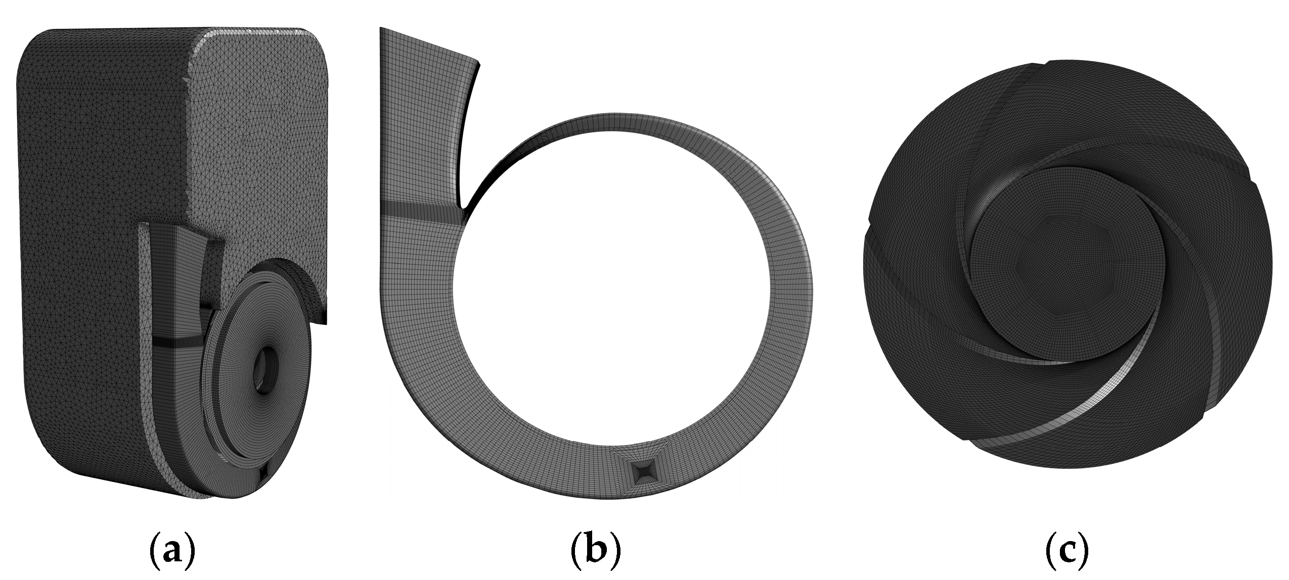
Physical diagrams of the self-priming pump (zx150-80) and the domain of the pump fluid are shown in Figure 1. The main performance parameters of the pump are Q = 120 m3/h, H = 75 m, n = 2950 r/min; the other geometric parameters are listed in Table 1.
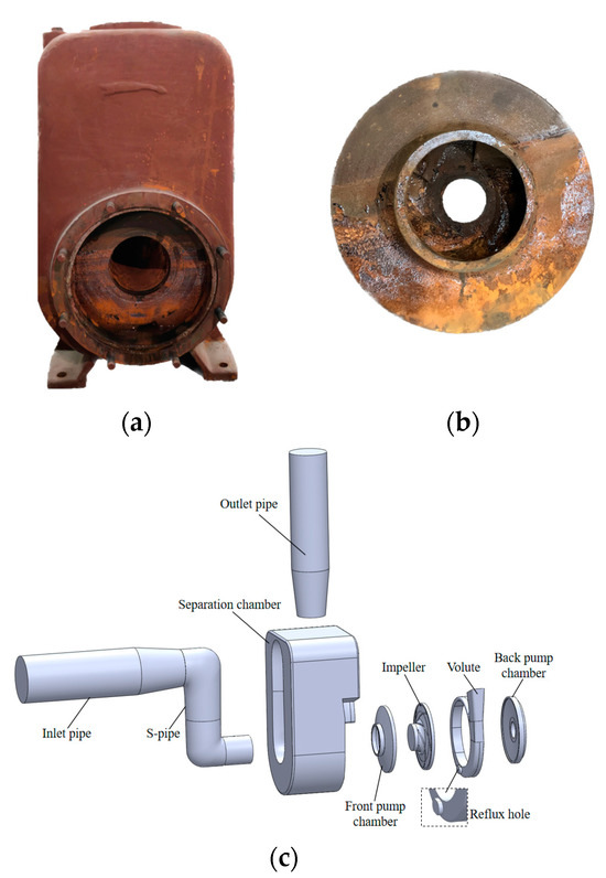
Figure 1.
Computational model of self-priming pump. (a) The self-priming pump. (b) Impeller. (c) Fluid computational domain.

Table 1.
Main geometric parameters of the self-priming pump.
2.2. Grid Independence Verification
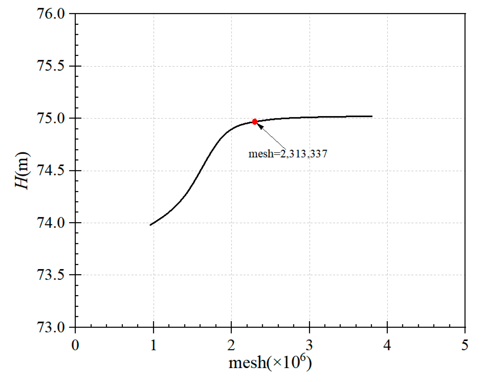
The computational domain is gridded using ANSYS ICEM 19.2. The self-priming pump grid is shown in Figure 2. To ensure that the number of grid cells does not affect the results of the calculations, the independence of the grid used to mesh the self-priming pump was verified. The results are shown in Figure 3. The head of the self-priming pump stabilizes as the number of grid cells for the self-priming pump reaches 2,313,337, and the grid numbers of the separation chamber, the volute, the impeller, the front and rear pump chambers, the S-pipe, the inlet piping, and the outlet piping are in the order 983,068, 335,082, 200,128, 192,216, 310,718, 179,550, and 112,575. Hexahedral structured grids were used for all overflow components in the self-priming pump, except for the gas–liquid separation chamber. The grid quality check revealed that grid quality was not less than 0.3 and the min angle was not less than 18°. This number of grids was still slightly insufficient for modeling the microscopic flow within the boundary layer, but it was sufficient for the prediction of the external properties and the capture of the macroscopic flow structure in the internal flow field.

Figure 2.
Grid diagram of the self-priming pump. (a) overall. (b) volute. (c) impeller.
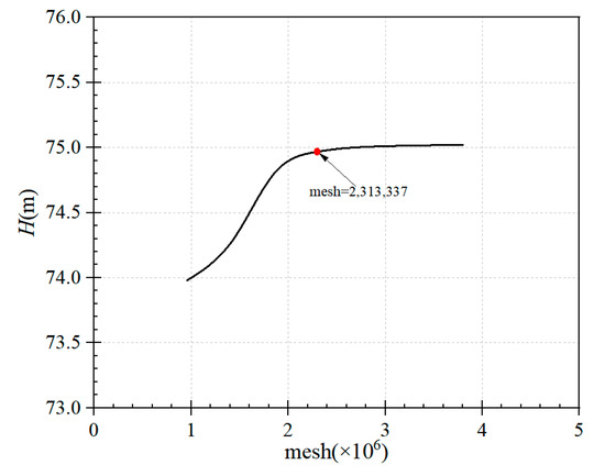
Figure 3.
Grid number independence.
2.3. Control Equations
The RNG k-ε model gives excellent computational results for pressure pulsation during the pump startup process [23,24]. Thus, the RNG k-ε two-square equation model was chosen to close the Reynolds mean equation for the calculation of nonconstant turbulence. The RNG k-ε model was obtained by improving the standard k-ε model using the prevailing time-averaged strain rate to increase the effect of the average strain rate [25]. The turbulence generation and turbulent kinetic energy dissipation equations in this model are the same as in the standard k-ε model, with only the constant term modified. Thus, for nonstationary, incompressible flow, the turbulent kinetic energy dissipation equation transforms to:
In the formula, u is the absolute velocity in the direction of x; μ is the viscosity coefficient of fluid; and δij is the Kronecker function.
To investigate the influence of flow rate on the pressure pulsation characteristics of self-priming pumps, three different flow conditions were selected for numerical calculations, namely 0.6 Qd, 1.0 Qd and 1.4 Qd. Considering viscosity, a no-slip boundary condition was used on the wall, the coupling of velocity and pressure was achieved using the SIMPLEC algorithm, and a default under-relaxation factor was used in the iterative calculations for all variables. In this calculation, the time required for 10 rotations of the impeller was set as the total time, and the time required for 3.9825° rotation of the impeller was 0.00025 s. Therefore, the final time step was set to be 0.00025 s, and the total time to be 0.225 s. The maximum number of iterations per time step was set to 50 to ensure absolute convergence at each time step, and the convergence residual was set to 0.001. The maximum number of iterations was set to be 0.001 for each time step.
2.4. Numerical Method Verification
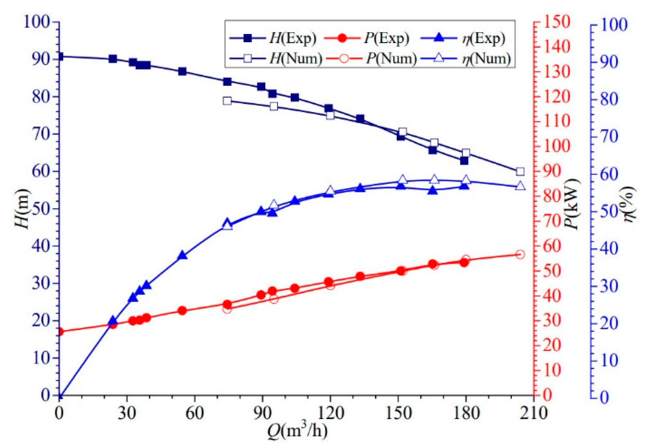
In order to confirm the reliability of the method of numerical calculation, external characterization tests of the pump were carried out. A comparison of the numerical calculation results with the experimental results is shown in Figure 4. The numerical calculation results are compared with experimental results in Figure 4. Under the rated flow of 120 m3/h, the experimental values for the head, efficiency, and shaft power were 76.93 m, 54.68%, and 45.67 kW, respectively. The numerical predictions for these quantities were 74.97 m, 55.48%, and 44.11 kW, respectively, corresponding to relative errors of 2.55%, −1.46%, and 3.41%, respectively; these deviations are all within reasonable limits. The predicted head, as well as the power, were a little below the test values for smaller flow ranges and a little above the test values for larger flow ranges. As for the efficiency, except for the significant difference between the efficiency at 166 m3/h, the deviation was small. In summary, the computational results are in close match with the test results, showing that the numerical scheme is accurate and the calculation results are reliable.
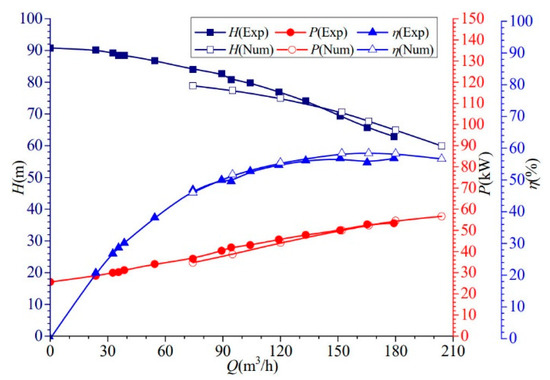
Figure 4.
Comparison of external characteristics.
3. Results Analysis
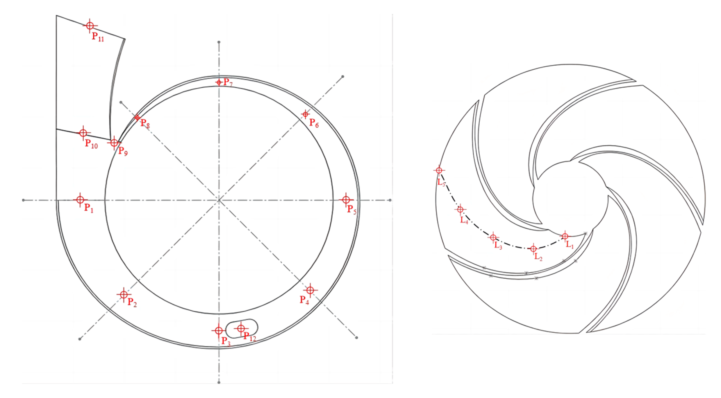
To analyze the changing behavior of pressure pulsation during the operation of the self-priming pump, the monitor points were set at the volute section, volute outlet section, tongue, reflux hole, and impeller channel centerline. The monitor points were located and named as shown in Figure 5. The monitor points in the volute were all distributed at 1/2 the thickness of the impeller, and the monitor points at the section of the volute are P1–8; the monitor point at the tongue is P9; the monitor points at the outlet section of the volute are P10–11, the monitor point at the reflux hole is P12, and the monitor points at the centerline of the impeller channel are L1–5.
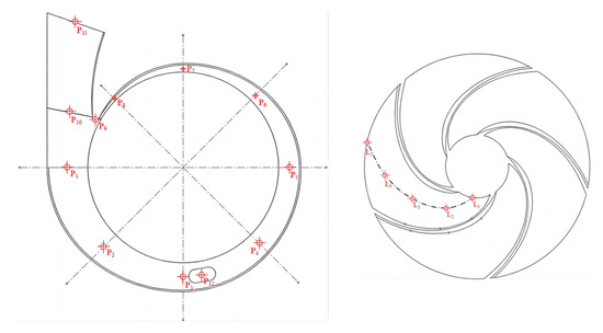
Figure 5.
Schematic diagram of the location of monitoring points.
3.1. Pressure Pulsation in the Volute Channel
The self-priming pump start-up process was numerically calculated for different flow conditions and the resulting pressure values were dimensionless and expressed in the average pressure coefficient Cp [26], the formula is as follows:
where U2 is the impeller outlet circumferential velocity, m/s; p is the transient static pressure, Pa; is the average static pressure at each monitoring point corresponding to 10 rotations of the impeller, Pa; ρ is the density of water, kg/m3.
In the process of this unsteady calculation, the process of 10 turns of impeller rotation was simulated. Due to the internal flow field of the self-priming pump in the pre-calculation period not being stable to minimize errors, the data of the final turn were selected for the analysis. The time-domain plots of pressure pulsations for eight sections of the volute under different flow conditions are shown in Figure 6. It can be observed that the pressure pulsation at the sections of the volute under the rated- and high-flow conditions shows a regular periodicity, and there are five peaks and valleys at each monitoring point in the cycle, mainly related to the rotational movement of the impeller. The amplitude of pressure pulsation at different section locations of monitoring points in the volute channel is different, the peaks of pressure pulsations are higher at P1 and P2, with the amplitude of 0.02388 and 0.02464 at the rated flow rate, as well as 0.03417 and 0.08326 at the high flow rate; the peaks at monitoring points 6 and 8 are smaller, with amplitudes of 0.00692 and 0.01061 at the rated flow rate, as well as 0.00941 and 0.00833 at the high flow rate. It is observed that the maximum values at the volute section are larger in high-flow conditions. In the low-flow condition, there is no obvious periodicity in the monitoring points on the volute section, and the trend of different monitoring points is not consistent; the largest value in the low-flow condition appears at monitoring point 5, which corresponds to the value of 0.01909, and the smallest value appears at monitoring point 3, which corresponds to the value of 0.00807. Comparing the time-domain plots of pressure pulsations at the volute section under the three flow conditions, it can be found that there is an obvious periodic pattern in the volute under the rated- and high-flow conditions; the amplitude of pressure pulsations is larger under the high-flow condition, especially at monitoring point 2, where there is an obvious periodic pattern in the volute under the rated- and high-flow conditions.
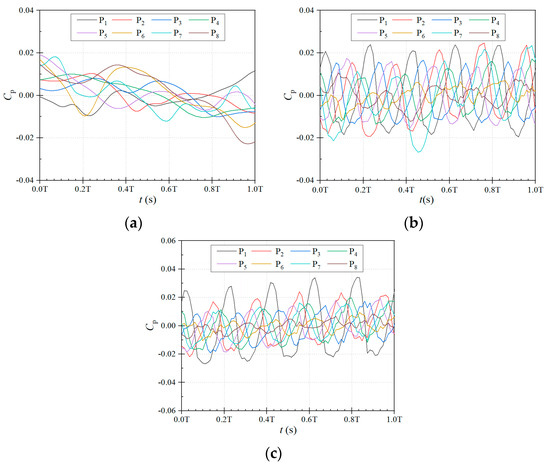
Figure 6.
Time–domain plots of pressure pulsation at the volute section under different flow conditions. (a) low flow rate. (b) rated flow rate. (c) high flow rate.
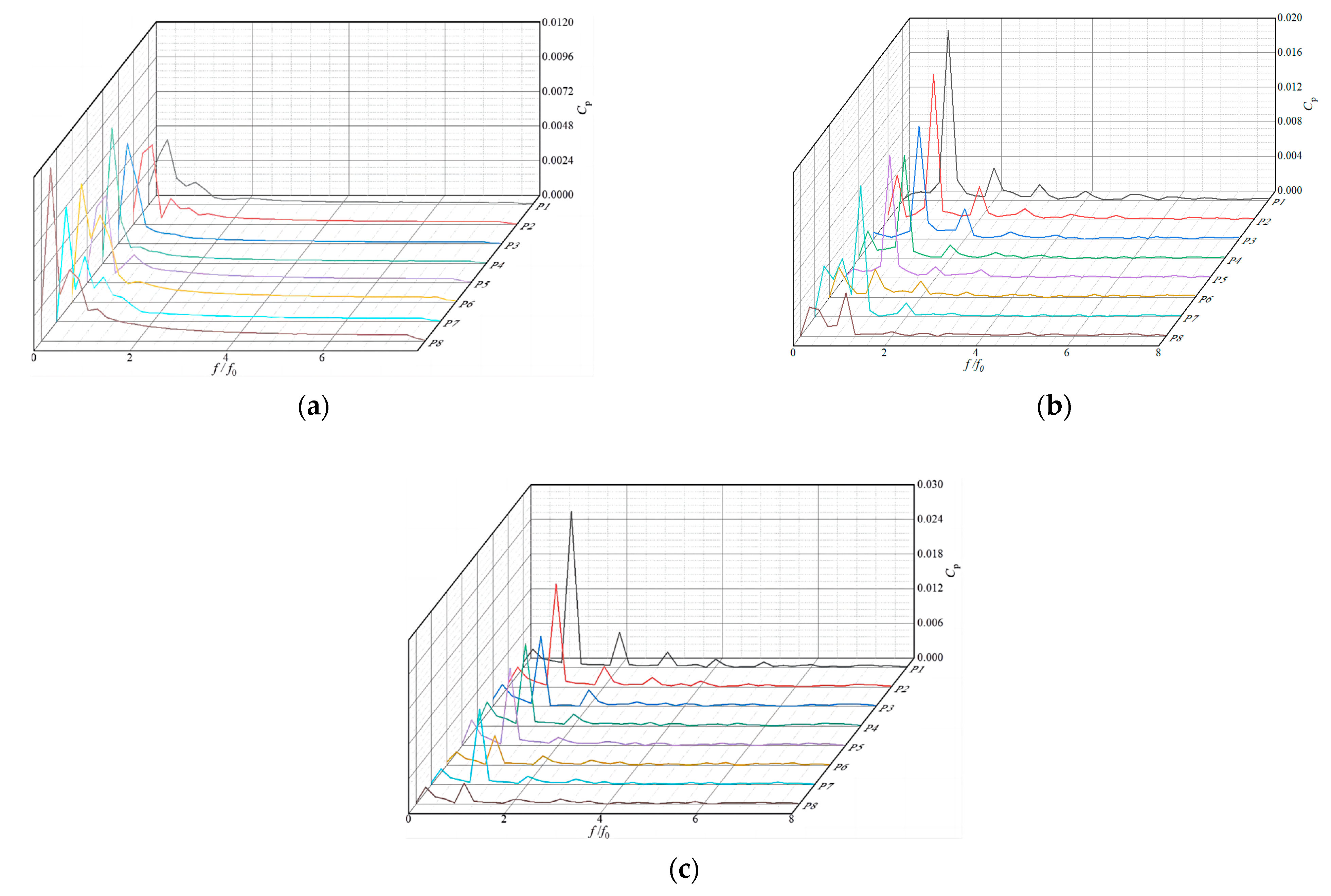
The speed of the self-priming pump used is 2950 r/min, the shaft frequency fz is 49.167 Hz, and the blade frequency f0 is 245.83 Hz. To compare the magnitude of the pressure pulsation amplitude at the monitoring point and the relationship between the amplitude and the frequency, the pressure pulsation signal is transformed by Fast Fourier Transform, and the pressure pulsation is obtained as shown in the frequency-domain plot. Figure 7 shows the frequency-domain plots of pressure pulsations at the monitoring points of the volute section with different flow conditions. The high-amplitude pressure pulsations generated at each monitoring point under the rated- and high-flow conditions all appear in the low-frequency band of the blade frequency, in which the peak value at 1 time the blade frequency is the largest. In the rated-flow condition, the main frequency peaks of the eight monitoring points are 0.01968, 0.01681, 0.01309, 0.01195, 0.01422, 0.00326, 0.01518, and 0.00504, and in the high-flow condition, the main frequency peaks of the eight monitoring points are 0.02709, 0.0178, 0.01218, 0.01425, 0.01339, 0.00514, 0.01297, and 0.00363. The peak pressure pulsation in the volute can be found to show a general trend of decreasing along the direction of impeller rotation, which is due to the flow structure of outlet return and flow separation. In the low-flow condition, the frequency-domain distribution at the section of the volute has no obvious regularity, and both the peak value and the trend of change are different from the other two conditions, and the peak value appears at 0.2 times the blade frequency, which is 0.00327, 0.00494, 0.00699, 0.00939, 0.00527, 0.00826, 0.00802, and 0.01206. In summary, for the monitoring points at the volute section, the frequency–domain distribution under the rated-flow and high-flow conditions has a certain regularity, and the high-amplitude pressure pulsation generated at each monitoring point appears in the octave band of the leaf frequency. The pressure pulsation peaks increase as the flow rate increases, with higher peaks occurring near sections I, II, and VIII.
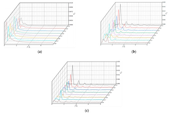
Figure 7.
Frequency-domain plots of pressure pulsation at the volute section during different flow conditions. (a) low flow rate. (b) rated flow rate. (c) high flow rate.
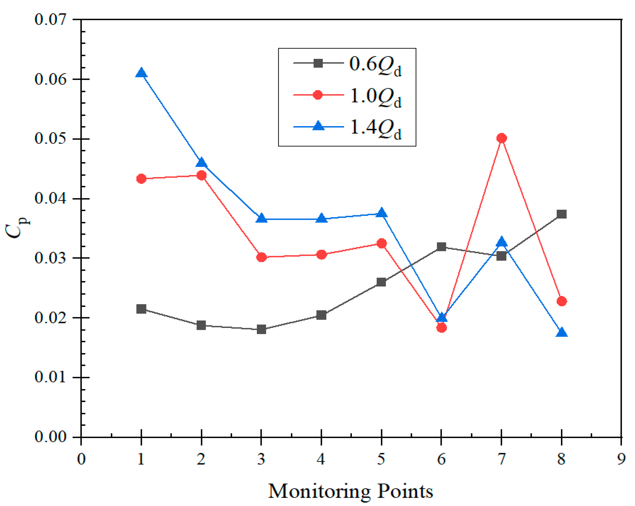
Figure 8 shows the distribution of the pressure pulsation amplitude in the volute section with different flow conditions. In the low-flow condition, with the rotational direction of the impeller, the amplitude of the monitor points on the cross-section exhibits a pattern of first decrease and then increase; in the rated-flow condition, it is larger in sections II and VII, with values of 0.04395 and 0.05019, and smaller in the VI and VIII sections, with values of 0.01839 and 0.02284. In the high-flow condition, the amplitude of the monitoring points in section I is significantly larger than that in the other sections, with a value of 0.061022. The amplitude in section VIII is the smallest, with a value of 0.01747. The larger amplitude represents intense pressure pulsation, i.e., the rotor–stator interaction of the impeller is strong, and the flow field structure inside the pump is unstable. Therefore, for the volute section of the self-priming pump, as the flow rate increases, the pressure pulsations become more intense and its internal flow field more unstable.
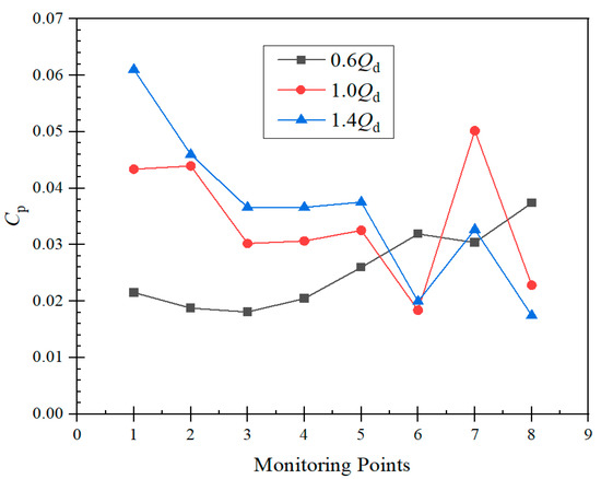
Figure 8.
Amplitude distribution of pressure pulsation at monitoring points of the volute section.
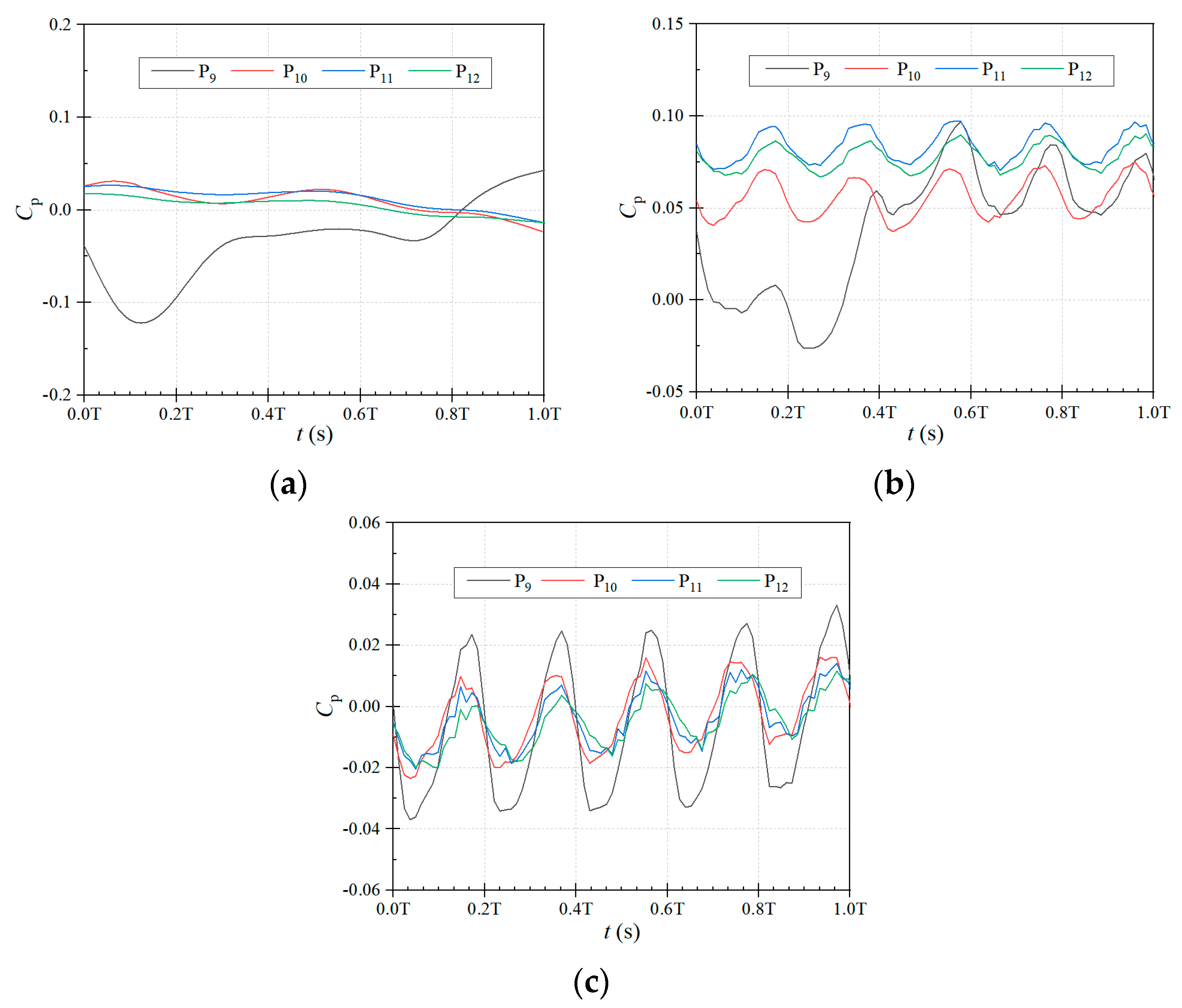
During the operation of the self-priming pump, the volute outlet, tongue, and reflux hole have obvious flow characteristics, so four monitor points are located at the above positions. Figure 9 displays a time–domain plot of the pressure pulsations at the tongue (P9), volute outlet channel (P10–11), and reflux hole (P12) with different flow conditions. In the low-flow condition, the pressure coefficient at the tongue location shows a decreasing and then increasing trend, reaching a minimum value of −0.12214 at 0.13 T and a maximum value of 0.04229 at 1.0 T; the monitoring points P10 and P11 at the outlet section of the volute show the same trend of evolution, which fluctuates within a certain range, but their periodicity is not obvious; the monitoring point P12 at the reflux hole, on the other hand, has a much smoother variation, the difference between the maximum and minimum values is only 0.03128 over the entire cycle. In the rated-flow condition, the tongues do not have a cyclic regularity in the stage of 0–0.42 T, after which, a cyclic regularity begins to appear and its peak value decreases; both monitoring points at the outlet section of the volute have a cyclicity, with a total of five peaks and valleys during the time of one rotation of the impeller. The monitoring point closer to the outlet section of the volute has a pressure coefficient that is 1.333 times that of the other monitoring point; the monitoring point at the return orifice has the same cyclicity as that of the outlet section of the volute, with both having five peaks and valleys, with values similar to those of P11. In the high-flow condition, the tongue is different from the other two conditions, the monitoring point is also periodic and its peak value increases with time; the outlet section of the volute is the same as the rated flow rate, and still has five peaks and valleys, but the value of the pressure coefficient close to the outlet of the volute is instead smaller than the other monitoring point, which is the opposite of the rated flow rate. In the position of the reflux hole, the value of the pressure coefficient is slightly smaller than that at the outlet of the volute. In summary, it was found that in the rated- and high-flow conditions, the outlet section of the volute and the reflux hole have obvious periodic patterns; however, no significant periodic pattern was observed in the low-flow conditions; the pressure coefficients in the high-flow conditions are significantly smaller than the pressure coefficients in the rated-flow conditions and slightly smaller than the pressure coefficients in the low-flow conditions.
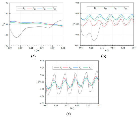
Figure 9.
Time–domain plots of monitoring points in the channel of the volute under different flow conditions. (a) low flow rate. (b) rated flow rate. (c) high flow rate.
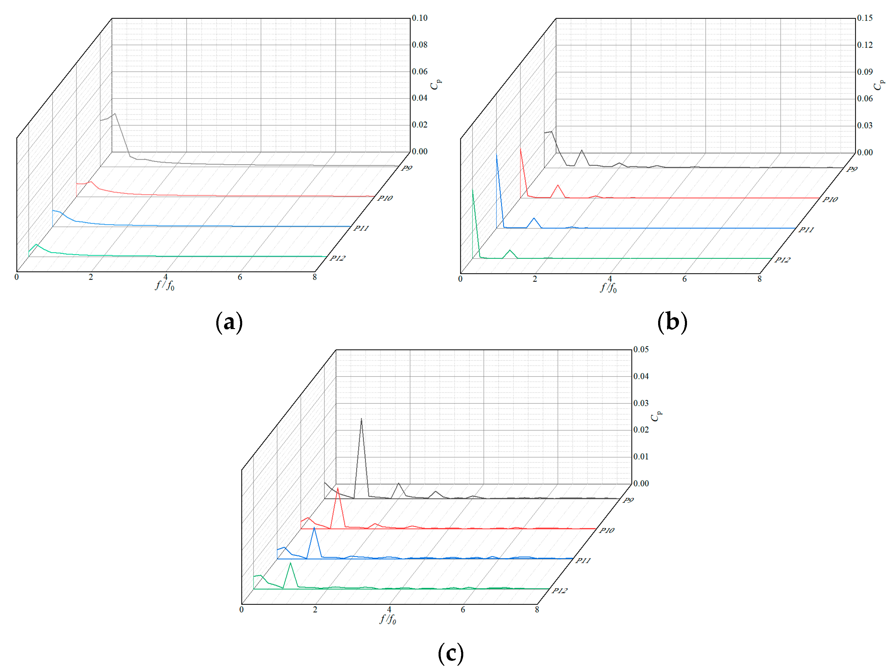
Figure 10 shows the pressure pulsation frequency-domain plots at the outlet flow channel, tongue, and reflux hole under different flow conditions. From the figure, it can be seen that under three different flow conditions, the pressure pulsation frequency-domain diagram shows different patterns. In the rated-flow condition, P9–12 have similar patterns, and the main frequencies are all distributed at one time the blade frequency, with peaks of 0.02013, 0.01477, 0.01162, and 0.00953, respectively. In the low-flow condition, the pressure pulsations at the four monitoring points show a unilateral decreasing trend as the frequency increases, and reach a peak at 0.4 f0 (two times the axial frequency), with peaks of 0.03988, 0.01141, 0.00712, and 0.00579, respectively. In the high-flow condition, the pressure pulsations are much more obvious than the two previous ones, and the maximum peaks are also found at one time the blade frequency, with peaks of 0.02994, 0.01535, 0.01185, and 0.00991, respectively. It was found that the pressure pulsation peaks at the outlet flow channel, tongue, and reflux hole also increase with the increase in the flow rate under different flow conditions.
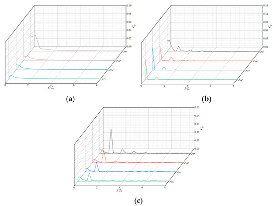
Figure 10.
Frequency-domain of the monitoring points in the flow channel of the volute under different flow conditions. (a) low flow rate. (b) rated flow rate. (c) high flow rate.
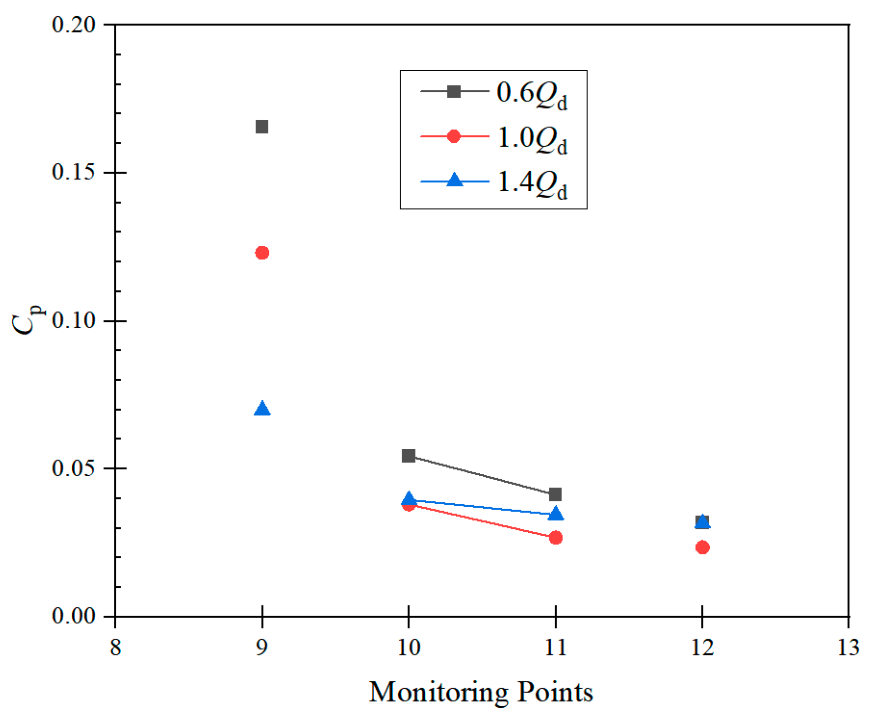
Figure 11 shows the distribution of pressure pulsation amplitude at the tongue, volute outlet section, and reflux hole with different flow conditions. In terms of the amplitude at the tongue, it is obvious that the larger the flow rate, the smaller its amplitude, i.e., the flow channel is more stable. For the volute outlet section, under the same flow condition, the closer the volute outlet, the smaller the amplitude; at the same monitoring point, the amplitude is largest in the low-flow condition, followed by the high flow rate and the minimum of the rated flow rate. For the reflux hole, there is little difference in amplitude at the low or high flow rates, both being 0.0316 and 0.02355 in the rated-flow condition.
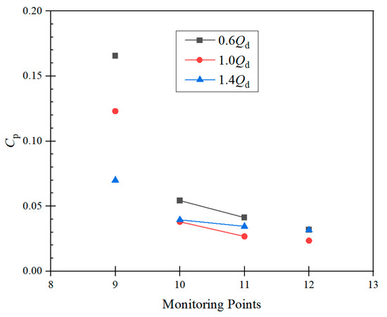
Figure 11.
Amplitude distribution of pressure pulsation at the monitoring points in the flow channel of the volute.
3.2. Pressure Pulsation in the Impeller Channel
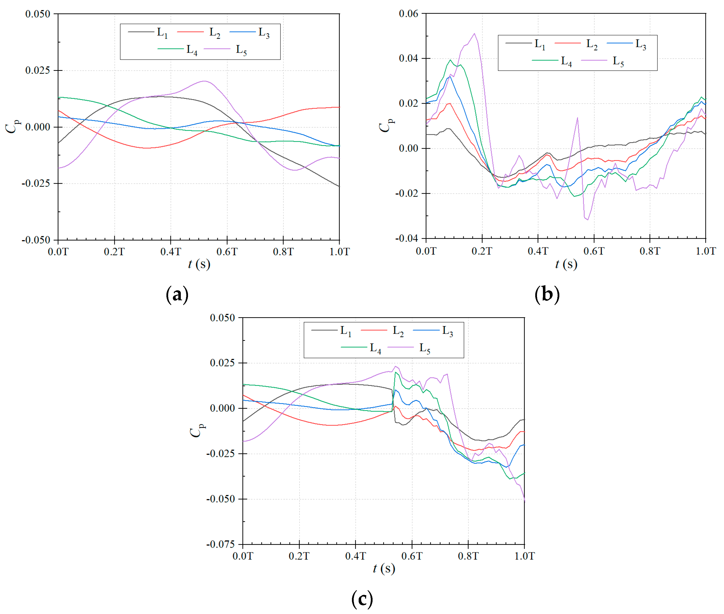
The flow conditions in the impeller channel are also extremely violent, especially near the impeller inlet and outlet locations. Figure 12 shows the time–domain pressure pulsations at the monitoring points L1–5 on the centerline of the impeller channel for different flow conditions. It can be seen from the figure that the monitoring points in the impeller channel show different trends under the three flow conditions. In the rated-flow condition, the monitoring points L2, L3, and L4 show a similar pattern of changing behavior during operation: all of them show the trend of first rising in the rapid decline, then fluctuation, and finally slowly rising. And all of them reach the maximum pressure coefficients of 0.02007, 0.03307, and 0.03947 at the peak value of 0.086 T. It can be seen from the figure that, inside the impeller channel, the closer to the outlet, the larger its pressure coefficient. L1 and L5 are close to the impeller inlet and outlet, respectively, which are affected by the impeller inlet flow and rotor–stator interaction, so that their time-domain curve changes are more drastic. In the low-flow condition, as the liquid flow rate in the pump decreases, the changes in the monitoring points also become smooth, and the amplitude of the pressure pulsation is reduced compared to the rated flow rate. Among them, the amplitude of the L1 and L5 monitoring points is much larger than that of the other three monitoring points, and this is determined by the location of the L1 and L5 monitoring points. In the high-flow condition, the pulsation amplitude of the time-domain curve is also smaller than that of the rated-flow condition, and the curve pattern is basically the same as that of the low-flow condition at 0–0.55 T, but there is a fluctuation interval between 0.55–0.72 T, and then it drops again after the fluctuation ends.
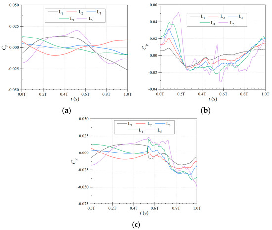
Figure 12.
Time-domain plots of monitoring points of impeller channel under different flow conditions. (a) low flow rate. (b) rated flow rate. (c) high flow rate.
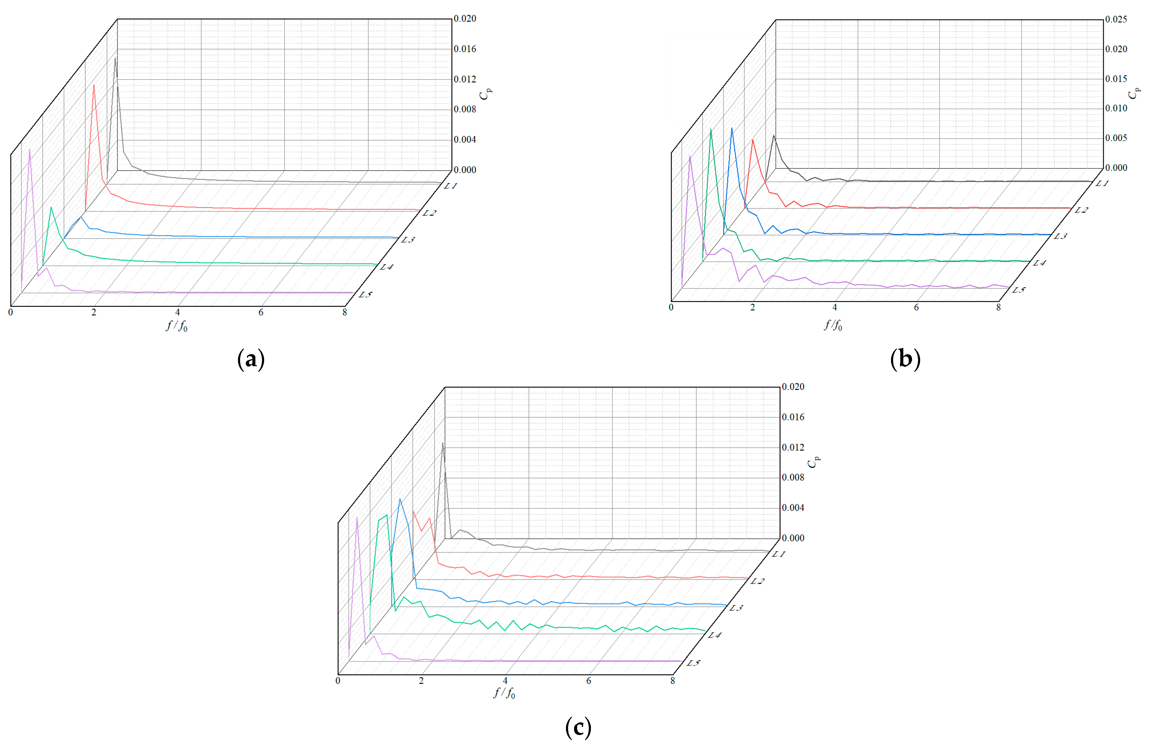
Figure 13 shows the pressure pulsation frequency-domain plot at the impeller midline monitoring point with different flow conditions. It can be seen that, in the low-flow conditions, the pressure coefficients of the four monitoring points decrease monotonically with the increase in frequency, and reach the maximum peak at 0.2 times the blade frequency, at 0.01668, 0.01668, 0.00178, 0.00772, and 0.01894, respectively. In the rated-flow condition, the peaks of the L1–4 monitoring points are only distributed before two times the blade frequency, and the peak distribution of the monitoring point L5 is more complicated than the other four, because it is closer to the impeller outlet. Because of its proximity to the impeller outlet, the peak distribution is more complicated than the other four, but the maximum values of the above five monitoring points all appear at 0.2 times the impeller frequency, and their peaks are at 0.00778, 0.01151, 0.01799, 0.02227, and 0.02227, respectively. In the high-flow conditions, compared with the previous two, its peak distribution is much more obvious and is distributed in low blade frequency, its maximum peak also appeared at 0.2 times the blade frequency, at this time the peaks are at 0.01448, 0.00636, 0.01422, 0.01492, and 0.01894, respectively. Some of the above characteristics in centrifugal pumps are similar to those in axial-flow pumps [27].
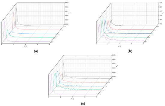
Figure 13.
Frequency-domain diagram of the monitoring points in the impeller channel under different flow conditions. (a) low flow rate. (b) rated flow rate. (c) high flow rate.
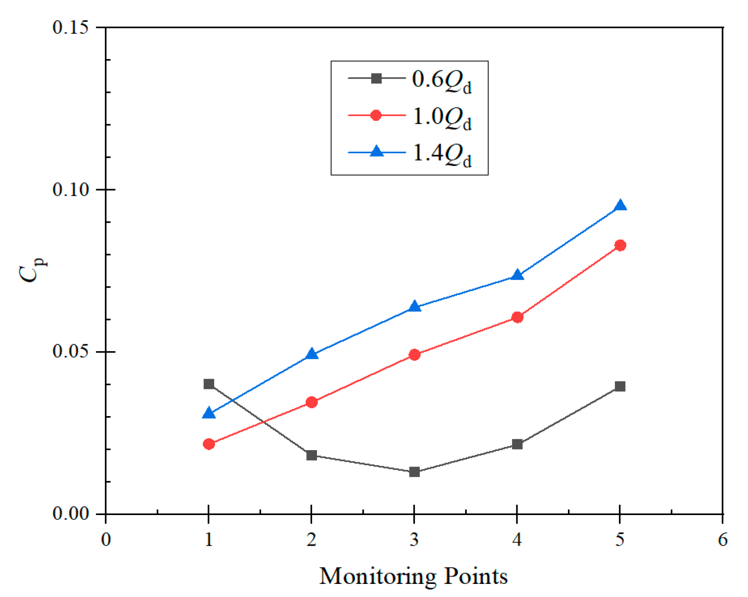
Figure 14 exhibits the pressure pulsation amplitude distribution at the monitoring points on the impeller midline with different flow conditions. In the low-flow condition, as the distance between the monitoring point and the impeller inlet increases, the amplitude of the pressure pulsation decreases and then increases, and the pressure pulsation under rated- and high-flow conditions gradually increases. It is also observed that the pressure pulsation amplitude at the impeller channel monitoring points increases gradually with an increasing flow rate.
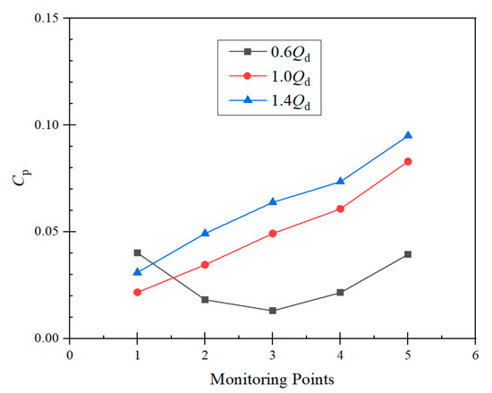
Figure 14.
Amplitude distribution of pressure pulsation at the monitoring points in the impeller channel.
The pressure distribution in the middle section of the pump under different flow conditions is shown in Figure 15. It can be clearly observed that, in the low-flow-rate condition, the pressure in the volute domain is significantly larger than other two flow conditions. In the low-flow-rate condition, the pressure in the volute channel is extremely high, with a maximum value of 800,000 Pa, while the pressure at the impeller inlet is negative. In the rated-flow-rate condition, the pressure in the volute domain is low, and the high-pressure area is mainly concentrated in the impeller outlet and the tongue area. In the high-flow-rate condition, the pressure in the volute channel is about 500,000 Pa, and the pressure in the impeller channel is larger as it is farther away from the inlet. It can be seen that in the operation of the self-priming pump, the pressure is higher in the low-flow-rate condition, followed by the high-flow rate, and the rated flow is the lowest.
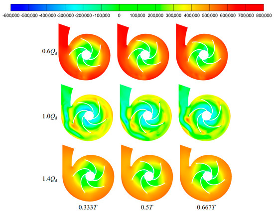
Figure 15.
Pressure distribution in the middle section of the pump under different flow conditions.
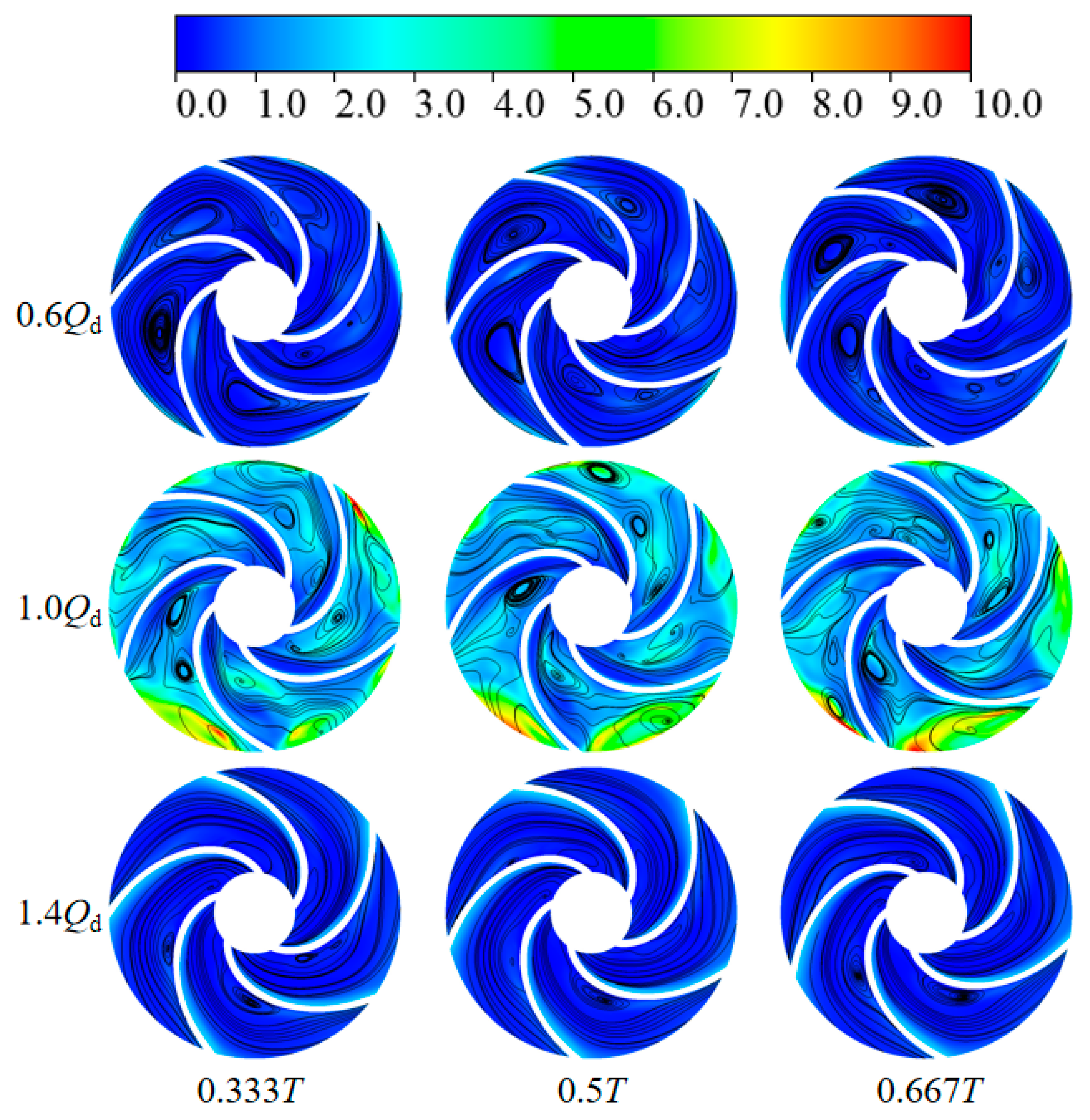
The distribution of turbulent kinetic energy and velocity streamlines in the impeller channel under different flow conditions are shown in Figure 16. From this figure, it can clearly be seen that the distribution of both turbulent kinetic energy and velocity streamlines at the rated flow rate is much more complicated than in the other conditions. In the low-flow-rate condition, there is a vortex in each impeller channel, and its position is close to the front side of the blade. In terms of the turbulent kinetic energy distribution, the turbulent kinetic energy distribution of the other positions is very low, except for the impeller outlet; that is, the flow is more stable. In the rated-flow-rate condition, the turbulent kinetic energy distribution in the impeller channel is much more complicated, most of the turbulent kinetic energy values are in the location of the larger vortex, and the number of vortexes in the impeller channel is much larger than in the low-flow-rate condition. In the high-flow-rate condition, the distribution of streamlines in the impeller channel is very uniform, which indicates that the flow in the impeller channel is very stable; as for the turbulent kinetic energy, the value on the back of the blade is larger. It can be seen that, in the pump operation process, the most complex flow takes place under the rated flow rate, followed by the low flow rate, and the high flow rate is the least complex.
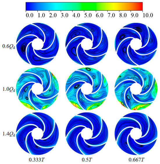
Figure 16.
Turbulent kinetic energy distribution in the impeller domain under different flow conditions.
3.3. Standard Deviation
The standard deviation [28] represents the average distance that the data deviates from the mean and is denoted by σ. The standard deviation is a reflection of the level of dispersion of the data set; as the standard deviation decreases, the less these values deviate from the mean, and vice versa. The standard deviation value is measured by the multiplicative link between the mean valve and the standard deviation. The overall standard deviation is the experimental standard deviation with an infinite number of measurements, also called the theoretical standard deviation. The formula is as follows:
where μ is the average value of the test data sample.
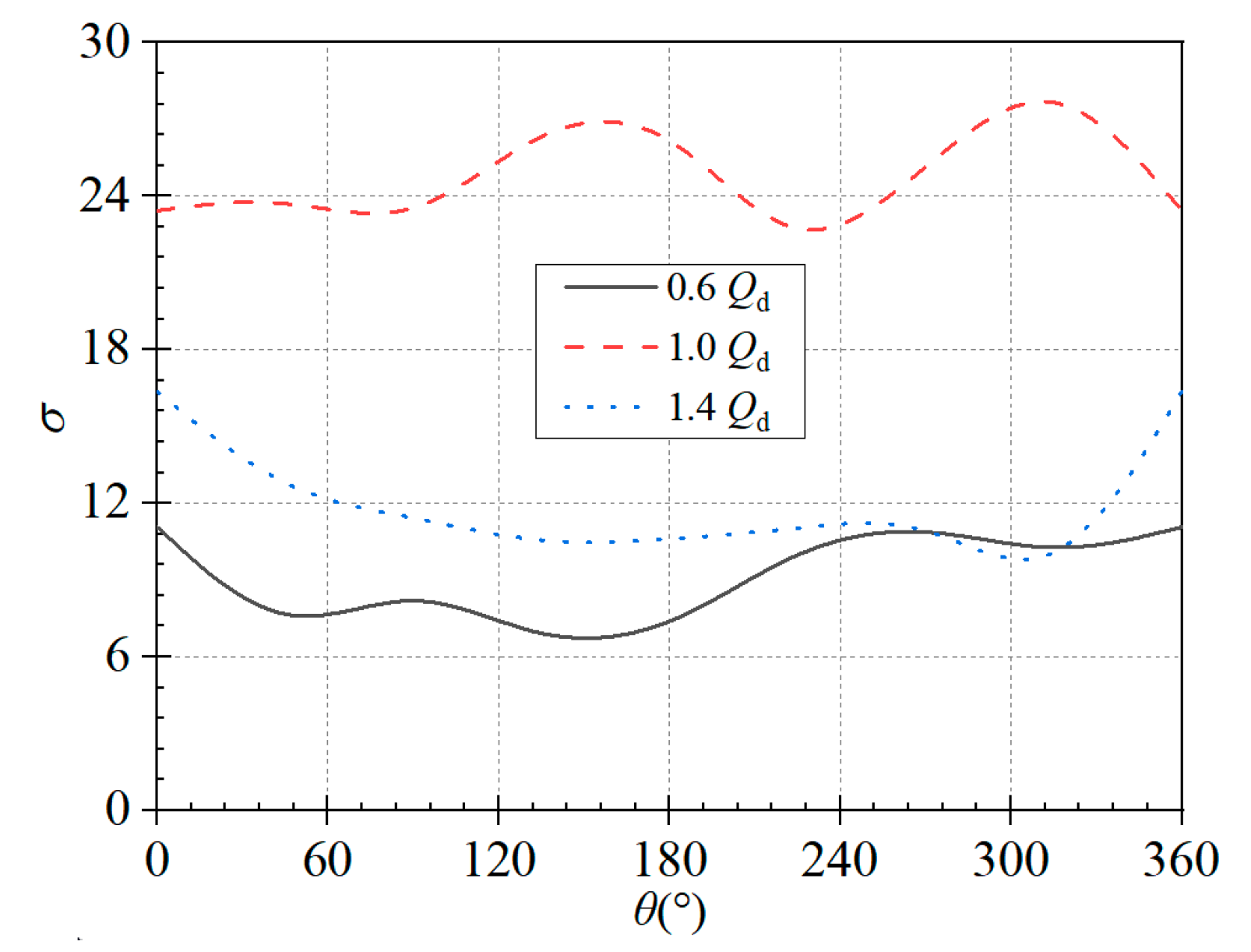
Figure 17 shows a plot of the standard deviation of the pressure coefficients at the monitoring points at eight sections of the volute during operation of the self-priming pump at the rated speed. As can be seen, in low-flow conditions, the standard deviation essentially fluctuates in the range of 6 to 12 [6, 12]; in the rated-flow condition, the standard deviation essentially fluctuates in the range of 21 to 30 [21, 30]; and in the high-flow condition, the standard deviation essentially fluctuates in the range of 8 to 17 [8, 17]. This fully indicates that during the self-priming pump operation process, the pressure pulsation in the volute basin is very obvious; and in the rated flow rate, the pressure pulsation is the largest, followed by the high-flow conditions, with the low-flow condition being the smallest.
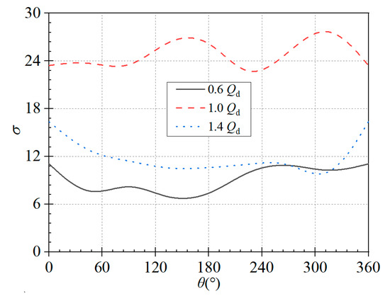
Figure 17.
Standard deviations distribution.
4. Discussions
In this numerical calculation, the pressure pulsation during the operation of the self-priming pump is comparatively analyzed under three stable flow rates (72 m3/h, 120 m3/h, and 168 m3/h) to investigate the influence of flow rate on the pressure pulsation characteristics. It can be seen that the best efficiency point for this type of self-priming pump is at 166 m3/h. At this point, Qd represents about 73% of the optimum flow rate, 0.6 Qd represents about 44%, and 1.4 Qd represents about 102% of the optimum flow rate. The defined low-, rated-, and high-flow conditions are inappropriate relative to the optimal flow rate. Therefore, in the next work, the number of selected flow conditions needs to be further increased, especially the high-flow conditions.
5. Conclusions
By comparing the pressure pulsation time-domain, frequency-domain, and amplitude distribution curves of the monitoring points in the volute and the impeller domains of self-priming pump, the differences in pressure pulsation between different flow conditions were explored, and the following conclusions can be made:
- (1)
- For the monitoring points at the volute section, the pressure pulsations in the time-domain and frequency-domain plots under the rated- and high-flow conditions have obvious periodic regularity, with the peak pressure pulsations occurring in the octave band of the blade frequency, and the amplitude of pressure pulsations under the high-flow condition is larger than that under the other two conditions.
- (2)
- The magnitude of pressure pulsations at L1 and L5 is larger at the monitoring points on the centerline of the impeller channel. Because L1 is close to the impeller inlet region, the fluid impacts the blade inlet, and L5 is close to the impeller outlet domain and is subject to outlet return flow and rotor–stator interaction effects.
- (3)
- During operation of the self-priming pump, the volute domain pressure pulsation is very complex, this part of the flow is extremely complex, and the pressure pulsation is largest at rated flow, followed by the high- and low-flow conditions.
Author Contributions
Conceptualization, L.-H.T.; Software, J.-F.L.; Investigation, Y.-J.Z., Y.-L.Z. and X.-W.X. All authors have read and agreed to the published version of the manuscript.
Funding
This research was financially supported by the Science and Technology Project of Quzhou (Grant Nos. 2023K256, 2022K98, and 2023NC08) and the Zhejiang Provincial Natural Science Foundation of China (Grant No. LZY21E050001).
Data Availability Statement
The data that support the findings of this study are available from the corresponding author upon reasonable request.
Conflicts of Interest
The authors declare no conflict of interest.
References
- Qian, H.; Mou, J.; Wu, D.; Ren, Y.; Zheng, S.; Zhu, Z. Experimental investigation on the gas-liquid flow patterns in a centrifugal pump during self-priming process. AIP Adv. 2020, 10, 015136. [Google Scholar] [CrossRef]
- Wang, C.; He, X.; Zhang, D.; Hu, B.; Shi, W. Numerical and experimental study of the self-priming process of a multistage self-priming centrifugal pump. Int. J. Energy Res. 2019, 43, 4074–4092. [Google Scholar] [CrossRef]
- Shepard, J. Self-priming pumps: An overview. World Pumps 2003, 444, 21–25. [Google Scholar]
- Wu, D.; Zhu, Z.; Ren, Y.; Gu, Y.; Zhou, P. Influence of blade profile on energy loss of sewage self-priming pump. J. Braz. Soc. Mech. Sci. Eng. 2019, 41, 470–484. [Google Scholar] [CrossRef]
- Gu, Y.; Yu, L.; Mou, J.; Wu, D.; Xu, M.; Zhou, P.; Ren, Y. Research strategies to develop environmentally friendly marine antifouling coatings. Mar. Drugs 2020, 18, 371. [Google Scholar] [CrossRef] [PubMed]
- Der, O.; Alqahtani, A.A.; Marengo, M.; Bertola, V. Characterization of polypropylene pulsating heat stripes: Effects of orientation, heat transfer fluid, and loop geometry. Appl. Therm. Eng. 2021, 184, 116304. [Google Scholar] [CrossRef]
- Luca, P.; Naoko, I.; Fabio, B. Pulsating heat pipes: Critical review on different experimental techniques. Exp. Therm. Fluid Sci. 2023, 148, 110980. [Google Scholar]
- Tan, L.; Niu, G.; Shi, W.; Shi, Z.; Chen, C. Experimental Investigation of Pressure Fluctuations for Centrifugal Pumps at Different Rotational Speed. J. Nantong Univ. (Nat. Sci. Ed.) 2020, 19, 56–63. [Google Scholar]
- Jiang, W.; Zhu, X.; Tian, H.; Li, G.; Wang, Y. Numerical and experimental study of influence of semi-high guide vane on pressure fluctuation in centrifugal pump. J. Cent. South Univ. 2021, 52, 1276–1286. [Google Scholar]
- Zhang, Y.; Li, J.; Wang, T.; Xiao, J.; Jia, X.; Zhang, L. Pressure distribution on the inner wall of the volute casing of a centrifugal pump. Sci. Technol. Nucl. Install. 2022, 2022, 3563459. [Google Scholar] [CrossRef]
- Sun, Z.; Wang, L.; Ge, H.; Yuan, H.; Tang, F. Experiment on pressure pulsation in impeller of large submersible tubular pump. Trans. Chin. Soc. Agric. Mach. 2023, 54, 155–160, 169. [Google Scholar]
- Gao, B.; Wang, Z.; Yang, L.; Du, W.; Wu, C. Analysis and test of performance and hydraulic excitation characteristics of centrifugal pump with different seal ring clearances. Trans. Chin. Soc. Agric. Eng. 2016, 34, 79–85. [Google Scholar]
- Xu, Z.; Li, Z.; Wang, W.; Wang, Q.; Xu, Y. Influence of air void fraction on pressure fluctuation of centrifugal aviation fuel pump blade. J. Drain. Irrig. Mach. Eng. 2023, 41, 239–246. [Google Scholar]
- Li, J.; Li, H.; Zhang, W.; Wang, Y.; Li, K.; Wang, S. Transient flow structures and pressure pulsations of a high-pressure aero-fuel centrifugal pump. J. Northwestern Polytech. Univ. 2022, 40, 199–205. [Google Scholar] [CrossRef]
- Yang, B.; Pan, Z.; Ibra, F. Analyses of gas-liquid two-phase flow and pressure fluctuation during start-up of municipal waterlogging self-priming pump. J. Jiangsu Univ. (Nat. Sci. Ed.) 2020, 41, 516–522. [Google Scholar]
- Liu, Z.; Kong, F.; Wang, Y.; Xie, S.; Zhao, L. Effect of unequal spacing blade distribution on pressure fluctuation of self-priming vortex pump. J. Drain. Irrig. Mach. Eng. 2017, 35, 113–118. [Google Scholar]
- Wang, Y.; Peng, S.; Liu, R.; Liu, Y. Numerical simulation of pressure fluctuation in self-priming vortex pump. J. Drain. Irrig. Mach. Eng. 2015, 33, 583–588. [Google Scholar]
- Wang, C.; Si, Y.; Liu, H.; Wu, Z.; Yi, T. Pressure fluctuation characteristics study of unsteady flow field on rotational flow self-priming pump. China Mech. Eng. 2009, 20, 2586–2590. [Google Scholar]
- Zhou, P.; Wu, Z.; Mou, J.; Wu, D.; Zheng, S.; Gu, Y. Effect of reflux hole on the transient flow characteristics of the self-priming sewage centrifugal pump. J. Appl. Fluid Mech. 2019, 12, 689–699. [Google Scholar] [CrossRef]
- Zhao, X.; Xiao, Y.; Wang, Z.; Luo, Y.; Cao, L. Unsteady flow and pressure pulsation characteristics analysis of rotating stall in centrifugal pumps under off-design conditions. J. Fluids Eng. 2018, 140, 021105. [Google Scholar] [CrossRef]
- Wang, C.; Zeng, C.; Yang, X.; Peng, H.; Liu, D. Numerical simulation and performance prediction of positive and negative internal flow field of double suction pump. J. Drain. Irrig. Mach. Eng. 2015, 33, 577–582. [Google Scholar]
- Chen, J.; Wang, Y.; Liu, H.; Shan, C.; Zhang, X. Internal flow and unsteady characteristics of ultra-low specific speed centrifugal pump. J. Drain. Irrig. Mach. Eng. 2018, 36, 377–383. [Google Scholar]
- Wang, K.; Zhao, Y.; Wang, S.; Xiao, Y.; Wang, C.; Zhang, J. Analysis of pressure fluctuation and internal flow characteristics of axial flow pumps under off design conditions. J. Hydroelectr. Eng. 2023, 42, 86–96. [Google Scholar]
- Yang, J.; Zhou, R.; Chen, H.; Yu, T. Transient flow characteristics and pressure pulsation characteristics at splitter of double-volute centrifugal pump during startup. J. Jiangsu Univ. (Nat. Sci. Ed.) 2021, 42, 278–283. [Google Scholar]
- Gan, G.; Duan, Y.; Yi, J.; Fu, Q.; Zhu, R.; Shi, W. Effect of tip clearance on the cavitation performance of high-speed pump-jet propeller. Process 2023, 11, 3050. [Google Scholar] [CrossRef]
- Mou, J.; Liu, J.; Zheng, S.; Gu, Y.; Dai, D.; Ma, Y. Effect of tongue on pressure fluctuation and internal flow in centrifugal pump. J. Cent. South Univ. (Sci. Technol.) 2016, 47, 4089–4097. [Google Scholar]
- Jia, X.; Shen, S.; Zhang, S.; Lv, H.; Lin, Z.; Zhu, Z. Influence of tip clearance on internal energy loss characteristics of axial flow pumps under different operating conditions. Phys. Fluids 2024, 36, 015102. [Google Scholar] [CrossRef]
- Zhang, Y.; Zhu, Z.; Li, W. Experiments on pressure distribution of a low specific-speed centrifugal pump with atypical open impeller. J. Chem. Eng. Jpn. 2020, 53, 237–245. [Google Scholar] [CrossRef]


Disclaimer/Publisher’s Note: The statements, opinions and data contained in all publications are solely those of the individual author(s) and contributor(s) and not of MDPI and/or the editor(s). MDPI and/or the editor(s) disclaim responsibility for any injury to people or property resulting from any ideas, methods, instructions or products referred to in the content. |
© 2024 by the authors. Licensee MDPI, Basel, Switzerland. This article is an open access article distributed under the terms and conditions of the Creative Commons Attribution (CC BY) license (https://creativecommons.org/licenses/by/4.0/).