Article

Prevention of Blowout Tests in Large-Diameter Boreholes with Soundless Chemical Demolition Agents and Fracturing Characteristics of Hard Sandstones

School of Energy Science and Engineering, Henan Polytechnic University, Jiaozuo 454003, China
*
Author to whom correspondence should be addressed.
Processes 2024, 12(2), 336; https://doi.org/10.3390/pr12020336
Submission received: 29 December 2023 / Revised: 30 January 2024 / Accepted: 2 February 2024 / Published: 4 February 2024
(This article belongs to the Special Issue Exploration, Exploitation and Utilization of Coal and Gas Resources)

Abstract

:
Increasing the diameter of the drillhole can facilitate drillhole breakage using soundless chemical demolition agents, but it is prone to cause drillhole blowout, resulting in crushing failure. This paper conducted a blowhole prevention test on a large borehole using the internal insertion cooling pipe method (ICBPM) to test the expansion pressure of cooling pipes with different diameters. During this test, a fracture occurred in a hole with a 75 mm inner diameter in the rectangular sandstone specimens with high strength. It was found that utilizing the ICBPM can effectively hinder the development of blowholes. Expansion and blowhole prevention are optimized with a 0.14 mass ratio of the cooling water to demolition agent and a maximum expansion stress of 49.0 MPa. The guiding effect of the minimum resistance line is significant. In repeated tests, all fissures are distributed in a Y-shape on the free surface where the minimum resistance line is located. The acoustic emission signals from statically fractured hard rock increase abruptly before damage, and the development of rock expansion and fracturing can be obtained through strain monitoring. These results suggest that the ICBPM can reduce the expansion time with a strong crushing effect, satisfying the need to process more crushing projects.

1. Introduction

The use of soundless chemical demolition agents (SCDAs) for rock breaking or demolition operations has the advantages of low engineering interference, producing no noise, no fire, and no toxic and harmful gases. SCDAs can be widely applied in densely populated urban demolition [1,2,3,4], protective demolition [5], coal rock crushing in mines, and other fields [6,7,8,9,10]. In addition, applying these agents can decrease the large quantity of explosives required, aiding environmental protection and engineering safety; also, it increases reservoir permeability, promoting the development of oil and gas resources [11,12,13]. However, the high temperatures and blowholes generated by the hydration reaction have limited the use and development of SCDAs. Calcium oxide (CaO) is the main ingredient of SCDAs (with a content of about 80–95%) [14,15,16], which generates a large amount of heat during the hydration reaction. If excessive heat is accumulated in the slurry and not released in time, it can easily cause violent reactions during the test, damaging the strain gauges or creating blowholes. In field applications, the emergence of boreholes affects the safety of the operators and leads to a decrease in expansion performance or even complete failure. Therefore, failure of the expansion pressure test due to high-temperature burning of the strain gauges or holes should be avoided. The “Chinese SCDA Expansion Pressure Test Standard” specifies that the test pipe should be submerged in a constant-temperature water tank for testing [17]. The high thermal conductivity of steel and the large specific heat capacity of water can be used to absorb the heat released by the hydration reaction, thus obtaining the expansion stress throughout the reaction process. The main mechanism of this reaction occurs when high temperature and vapor pressure cannot be formed under a favorable heat dissipation environment, which delays the hydration reaction of SCDAs. However, the expansion time and pressures in engineering field applications differ from those under the test environment, and the flooded engineering conditions can hardly be achieved.
In response to these disadvantages, many scholars developed new test methods. Dai et al. [18] used the hydraulic balancing instrument to test the expansion pressure by recording the pressure gauge data. Wang et al. [19] developed a pressure ring test system to measure expansion pressure by recording the displacement with a micrometer. Dai et al. [20,21] and Qiu et al. [22] employed the axial expansion pressure test method to record the expansion pressure data by replacing the step of manually reading pressure gages with an electro-hydraulic servo pressure tester. The test recording process was simplified, and the accuracy of numerical recording was improved. Xu et al. [17] fabricated thickened aluminum alloy cylinders to replace seamless steel tubes based on the outer tube method and tested the expansion pressure by recording the strain at the end surface of the cylinders. The thickened aluminum alloy cylinders increased the thermal conductivity paths and reduced the surface temperature of the cylinders. The above studies extended the expansion pressure test method. Using micrometers and hydraulic gauges instead of strain gauges can avoid or reduce the effect of the heat of hydration on the latter. However, the calibration of the test equipment is technically demanding and costly, making it difficult to become a universal test method. In addition, the closed container prevents heat dissipation inside the borehole, which can easily induce SCDAs to blow holes inside the container. It results in energy release in the axial direction of the borehole, causing test failure or data errors. When using SCDAs in the field, the main method to prevent blowholes from forming is to minimize the diameter of holes, which is usually Φ = 30~45 mm with spacing less than 500 mm [23,24]. Small borehole diameters lead to low expansion pressure and a high number of drilling jobs, greatly limiting the application of expansion agents.
To solve the exothermic and blowhole problems of the SCDA hydration reaction, other scholars have controlled the water absorption and hydration reaction rate of SCDAs by physical cooling [25], optimizing the group distribution ratio or special loading structures [26,27]. Although the above research demonstrated a certain explosion-proof effect, the test was still dominated by boreholes with a small diameter, and the variation of components significantly affected the expansion performance. Further research is still needed for the investigation of the expansion performance and crushing effect under large-diameter drilling conditions.
In summary, the SCDA hydration reaction generates expansion pressure and causes problems such as violent reactions and high exothermicity. The high temperature and blowhole caused by the exothermic heat become the major constraints to the use and development of SCDAs. In this study, a cooling tube was inserted into the center of a large borehole to prevent the emergence of small boreholes by cooling the slurry from the inside, and the effect of the cooling tube diameter on the expansion performance was tested. Furthermore, this method was used to fracture hard rock samples, and the fragmentation characteristics of hard rock in the static fracturing process were investigated. The findings of this study provide a reference for the application of expansion agents under large borehole conditions.

2. Blowhole Mechanism and SCDA Blowhole Prevention Method

2.1. Characteristics and Mechanism of the Blowhole

CaO is the main component of SCDA expansion material, which is mixed with water in a certain proportion and expands and releases heat after hydration [21,28]. The hydration reaction can be expressed by Equation (1) as follows:
C a O + H 2 O = C a ( O H ) 2 + 64.9   k J 56 18 74
where 56, 18, and 74 represent the molar mass of CaO, H2O, and Ca(OH)2, respectively.
According to Equation (1), 1 mol of water fully reacts with 1 mol of calcium oxide in a mass ratio of 0.32, releasing 64.9 kJ of heat. The content of CaO in commonly used SCDA is about 80%, and the heat released by 1 kg of SCDA is 928.1 kJ, allowing 2.8 kg of water to be heated from 20 °C to 100 °C. Higher temperatures vaporize the free water in the slurry to produce steam pressure. When the steam pressure exceeds the expansion pressure of the SCDA and the friction in the borehole, the energy is released instantly along the borehole axis, accompanied by a large amount of slurry and water vapor ejection. Figure 1 shows the state of spraying holes in the steel pipe after 1–2 h of slurry injection. The length of the steel pipe is 1000 mm, and the inner diameters are 40 mm and 75 mm. The SCDA is type II, applicable to the ambient temperature of 10–30 °C. The water/cement ratio is 0.34, the test ambient temperature is 20 ± 2 °C, and the armored thermocouple is within the range of 0–500 °C.
A punch typically occurs suddenly and has potential hazards. Figure 1 shows the state of the SCDA after punching. At the occurrence of this event, the rapidly discharged steam from the orifice area causes substantial SCDA ejection from the borehole. Despite this, a minor portion of the SCDA remains, and the pipe is undamaged. This indicates a slight expansion pressure in the radial directions of the borehole during punching. Consequently, the prevalent SCDA around the borehole is in powdered form and has lost its expansion capabilities.
To prevent the development of blowholes, some scholars proposed to seal the orifices by machining flanges or plugs on the steel pipe ports, as shown in Figure 2. The inner diameter of the steel pipe is 40 mm, and its length is 1000 mm. Armored thermocouples with a range of 0–500 °C are used, and the slurry is injected and sealed with a threaded plug cap.
According to Figure 2, heat is prone to accumulate when using the plugging method due to the blockage of heat released from the orifice. Once the plugging is not secure, more serious blowholes will occur. Under clogging conditions, the blowholes are more intense, and the energy is ejected from the mouth of the steel pipe, cutting the blocking cap off along the orifice and leaving an intact body of the steel pipe.
The whole process of the SCDA reaction is accompanied by temperature changes, and a temperature increase is an important feature of SCDA hydration reaction and hole blowing. Figure 3 shows the temperature changes of the SCDA slurry hydration reaction tested with thermocouples at different internal diameters and hole-sealing conditions.
As shown in Figure 3, the tube diameter and sealing conditions affect the reaction rate and temperature of the SCDA. The temperature change curve can be generally divided into three stages based on the increasing trend of temperature. Stage I: Initial condensation after filling with the SCDA (at about 1.5 h), with the tube temperature matching the ambient temperature. Stage II: The initial condensation state is transformed into the final condensation state, followed by expansion. Expansion pressure and friction are generated in the steel pipe, causing heat accumulation inside the steel pipe and accelerating the hydration reaction process. Stage III: The energy imbalance state, where heat vaporizes the water in the free state to form vapor pressure. When the vapor pressure exceeds the expansion pressure and pipe wall friction, the water-hardening material blocks the heat dissipation channel, the equilibrium state is disturbed, and heat and water vapor carrying a large amount of the SCDA is ejected from the borehole. It was found that the sealed boreholes with an inner diameter of 40 mm and the unsealed ones with a 75 mm inner diameter had lower punching temperatures and required less time for a reaction to occur. In contrast, the unsealed boreholes (inner diameter = 40 mm) exhibited a relatively high punching temperature, resulting in elongated time. The reason for this is that a sealed environment enhances vapor pressure, resulting in a reduction in the hydration reaction time and temperature. In the case of the 75 mm inner diameter, the increase in the borehole diameter improves steam discharge and promotes the hydration reaction, elevating the vapor pressure rapidly. It can be inferred that a larger-diameter borehole is easier to punch. Conversely, vapor pressure accumulation is challenging for unsealed holes with an inner diameter of 40 mm. As a result, the hydration reaction time is longer, and the required punching temperature is higher.
According to the test results, Stage II (i.e., the stage when the initial consolidation state is transformed into the final consolidation state) is the critical period for preventing blowholes. Figure 4 explains the expansion mechanism of the SCDA hydration reaction in a water bath and in a room environment at a constant temperature.
As shown in Figure 4, at the initial stage, the hydration reaction on the surface of CaO particles generates water-hardening cementing substances, such as calcium silicate and calcium aluminates, enabling us to control the cementation and CaO hydration rate, which corresponds to Stage I in Figure 3. As the reaction proceeds, the CaO hydration reaction generates Ca(OH)2 crystals and releases heat. The water in the slurry absorbs heat through surface cementation and gradually forms vapor pressure, while the crystals grow and are constrained by the drilled holes, extruding and cementing each other to produce expansion pressure. The SCDA slurry is transformed from the initial condensation to the final condensation state. In the constant-temperature water bath environment, the heat released from the CaO hydration reaction is rapidly absorbed by the water outside the steel tube. Because there is no heat accumulation inside the borehole, no vapor pressure is generated, and the Ca(OH)2 crystals on the surface of the CaO particles gradually increase, ultimately squeezing each other inside the constraints to form hard cement. The Ca(OH)2 crystals generate outward expansion pressure under constraints and inwardly hinder the water molecules from entering the interior of the particles to undergo hydration with CaO. As a result, the expansion stress undergoes a process of rapid growth and slow growth until it stops. In a constant-temperature indoor environment, the heat released from the hydration reaction of CaO particles cannot be absorbed easily by the surrounding environment in time. The heat accumulated in the borehole increases its temperature, and the vaporization of water in the slurry generates vapor pressure. Due to the blockage of pores by water-hardened substances such as Ca(OH)2, the vapor pressure accumulates in the borehole and cannot be released. The blowhole occurs when the vapor pressure exceeds the radial expansion pressure and internal friction, and the high-temperature water vapor carrying a large amount of heat leads to the instant blowing of the slurry from the hole.

2.2. Anti-Blowout Mechanism and Anti-Blowout Effect of the ICBPM

The temperature change curve of the slurry and the expansion mechanism of the hydration reaction during the creation of a blowhole indicate significant stage characteristics in the actual working environment. When heat dissipation conditions are available during the hydration reaction, the blowhole can be avoided. The ICBPM involves the injection of freshwater into a cooling pipe (smaller in diameter than the drilled hole), followed by the injection of prepared slurry. In the early stage of expansion (Stage II), the heat generated by the hydration reaction is promptly absorbed by the water in the cooling pipe, decreasing the heat accumulation and steam pressure inside the slurry. In the late stage of the hydration reaction, Ca(OH)2 prevents water molecules from entering the internal particles and leads to less heat generation. The solid-phase expansion increases the expansion pressure and friction to prevent blowholes. Table 1 shows the experimental parameters of the ICBPM.
After fixing the steel pipe, one end of the cooling pipe was blocked and placed in the test steel pipe. Water was added to the cooling pipe until it was flush with the upper surface of the steel pipe. Subsequently, the slurry was prepared with a water/cement ratio of 0.34 and poured into the steel pipe to await the hydration reaction. Figure 5 shows the results of the blowhole prevention test.
It can be seen from Figure 5 that the ICBPM is effective in preventing blowouts. A small amount of slurry was ejected from the steel pipe orifice, indicating that the slurry mainly expanded in the radial direction within the borehole. After cutting the steel pipe, it was found that the Ca(OH)2 generated inside the borehole was constrained by the borehole wall and became compact to form a hard cement after volume expansion. This phenomenon is consistent with the morphology of the SCDA after expansion under the environment of a constant-temperature water bath, further demonstrating the effectiveness and feasibility of the ICBPM.

3. Expansion Performance Test of the ICBPM

3.1. Expansion Performance Test

In addition to the effectiveness of the ICBPM, the expansion performance of the slurry after inserting the cooling tube inside the slurry body still needs further investigation. The outer pipe method is a well-established method for expansion stress testing [29,30]. The specific step is to inject the SCDA slurry into the steel pipe, and the expansion of the slurry inside the steel pipe causes the external deformation of the steel pipe. The expansion stress is back-calculated by recording the strain of the steel pipe based on the thick-walled cylinder theory of elastomechanics [28,31]:
σ ρ = a 2 b 2 b 2 a 2 P 2 P 1 ρ 2 + a 2 P 1 b 2 P 2 b 2 a 2
σ φ = a 2 b 2 b 2 a 2 P 2 P 2 ρ 2 + a 2 P 1 b 2 P 2 b 2 a 2
where σ ρ is the radial positive stress in the cylinder; σ φ is the circumferential positive stress in the cylinder; a and b are the inner and outer diameters of the cylinder, respectively; P 2 is the pressure on the outer wall of the cylinder; P 1 is the pressure on the inner wall of the cylinder; and ρ is the distance from the radial point to the center of the cylinder.
When the outer wall of the cylinder is not under pressure, the cylinder is only subjected to the pressure of the inner wall, and the stress on the outer wall of the cylinder is transformed into the following:
σ φ = 2 a 2 P 1 b 2 a 2
According to Hooke’s law for plane stress problems in polar coordinates, we can obtain the following:
ε ρ = 1 E σ ρ ν σ φ
ε φ = 1 E σ φ ν σ ρ
After substituting Equations (5) and (6) into Equation (4), the following equation can be obtained:
P 1 = b 2 a 2 E ε φ + ν ε b 2 1 ν 2 a 2
Further simplification gives the following:
P = k 2 1 E ε φ + ν ε b 2 1 ν 2
where P is the internal expansion pressure of the steel pipe; k is the constraint coefficient, i.e., the ratio of the outer diameter to the inner diameter of the steel pipe; ε φ and ε b are the annular and axial strains of the steel pipe, respectively; ν is the Poisson’s ratio of the steel pipe, taken as 0.3; and E is the elastic modulus of the steel pipe, taken as 200 GPa.
The expansion properties of the ICBPM were tested using the outer pipe method, and the control group was tested for expansion stress in a constant-temperature water bath environment. The test program and parameters are shown in Table 2.
Seamless steel tubes with inner diameters of 40 and 75 mm were selected for the test boreholes (500 mm in height), and the base of these tubes was welded with a 10 mm thick steel plate. The thermostatic water bath was conducted in a tank environment (denoted as T), and room temperature (denoted as N) was used for the internal cooling test. For example, T75C3 indicates that a C3 cooling tube is inserted into a drilled hole with an inner diameter of 75 mm in a tank environment. The theoretical constraint coefficients for thick-walled cylinders are calculated as follows [32]:
b a a > 1 20
where b and a represent the outer and inner diameters of the borehole, mm.
A small constraint coefficient can easily lead to the steel pipe yielding or the fracture of the strain gauges. The constraint coefficient of the test steel pipe was 0.2, and the elasticity coefficient was 200 GPa. The DH3816N strain collector was employed. It should be noted that to avoid the false strains produced by the high temperature in the ICBPM test, BAB120-3AA250 high-temperature strain gauges with a resistance value of (120 ± 0.2) Ω were selected and designed to operate within 0–250 °C, and the 1/4 bridge configuration was utilized for electrical connection. The ordinary galvanized steel tubes were adopted for cooling and divided into C1, C2, and C3 modes according to the tube diameter and wall thickness. A K-type armored thermocouple (range 0–500 °C) was used. Figure 6 schematically showcases the test equipment and sensor arrangement.
Specifically, the thermocouples and strain gauges were arranged at a 25 cm depth in the middle of the steel pipe, with three transverse strain gauges evenly distributed along the annulus of the borehole (C) and one vertical strain gauge along the axial direction of the borehole (A) to measure the strains in the two directions. Foam cotton was wrapped around the outside of the thermocouple in the water tank environment to reduce the heat absorption effect of the water on the thermocouple. The equipment was installed and filled with SCDA slurry for the reaction.

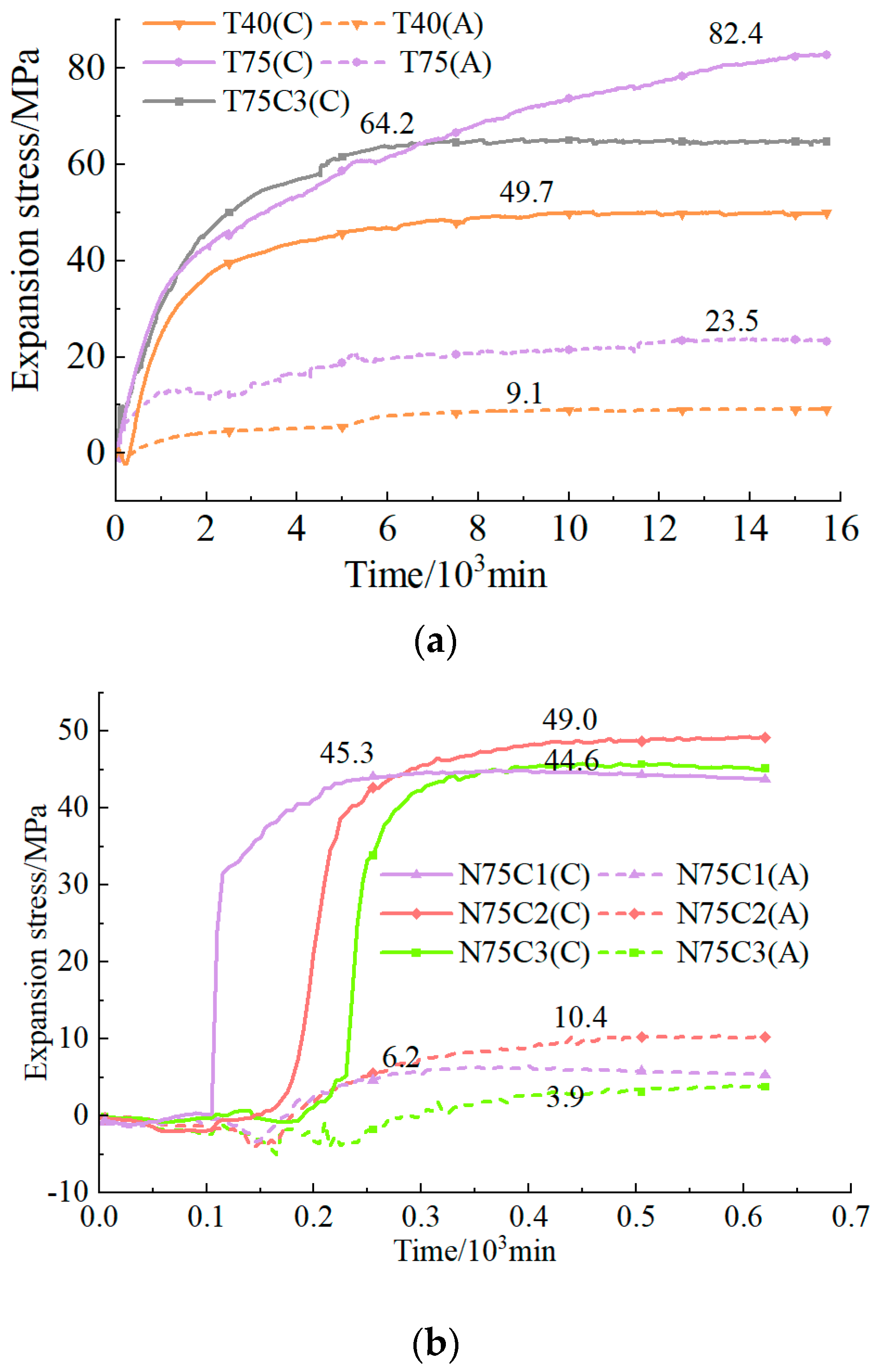
3.2. Test Results and Analyses

This paper compared the test results considering the macro-expansion effect, expansion pressure, and temperature data under a constant-temperature water bath and internal cooling conditions to study the expansion performance of the ICBPM and its characteristics at different depths. Figure 7 shows the macro-expansion effect of the expansion pressure test under the two conditions.
As shown in Figure 7a, in a constant-temperature water bath, the heat generated from the hydration reaction of the SCDA slurry is rapidly absorbed by the peripheral water of the steel pipe, and no punching in the hole occurs during the test. The expansion of SCDA is dominated by the circumferential expansion. At the mouth of the hole, due to constraints and the reduced friction force, the SCDA appears in the form of powder and a small amount of overflow with a height of 3–5 cm, and the inside of the drilled hole is a hard colloid. Figure 7b displays the blowout prevention effect of the ICBPM. A small amount of slurry and hot water splashed at the borehole entrance during the N75C1 test, indicating the highly intense hydration reaction inside the borehole. In addition to the phenomenon at the orifice, the remaining SCDA in the borehole is still a tightly extruded hard colloid. In this sense, the cooling pipe exerts a good effect in preventing blowout, and the slurry in the borehole retains a strong expansion capacity. The blowout prevention effect of the C2 and C3 cooling pipes is better than that of the C1 pipe since no blowhole and cooling water splash occurred during the experiment, and a hard collodion was formed inside the borehole. According to Figure 7, the slurry inside the borehole under both experimental conditions is extruded, dense, and hard collodion, indicating that the internal cooling method has a significant blowout prevention effect. In addition, this effect is related to the cooling pipe and a larger cooling pipe diameter embraces a greater amount of cooling water that lowers the content of the slurry, thus improving the blowout prevention effect.
To grasp the expansion performance of the ICBPM, the expansion stress data under both test environments were compared and analyzed. Figure 8 shows the time variation curves concerning the expansion stress under the constant-temperature water bath and ICBPM conditions.
Figure 8a demonstrates the time–expansion stress curves in a constant-temperature water bath. With the increase in the hole’s diameter, the annular and axial expansion stresses show an increasing trend, and the former is much larger than the latter, indicating that the pipe crack is mainly expanded in the annular direction. Specifically, the annular and axial expansion stresses at T40 are 49.7 and 9.1 MPa, respectively. The annular expansion stress of T75C3 is 64.2 MPa, in between that of T40 and T75. T75’s expansion performance is the best among all test groups, with expansion stresses in annular and axial directions of 82.4 and 23.5 MPa, respectively. Based on the analysis of the expansion stress development, the expansion stress after slurry filling experiences static, rapid, and slow growth stages until it stabilizes, and, thereafter, the expansion curve is smooth, indicating no sudden changes. After filling at the rapid growth stage, the expansion time is prolonged for 3000–5000 min. The reason for this is that in the water bath environment, due to the large specific heat capacity of water and the good thermal conductivity of the steel pipe, the heat can be absorbed by the surrounding water in time, and no vapor pressures are formed inside the steel pipe, indicating that the expansion pressure of the steel pipe is mainly a result of the expanded volume of the solid phase. The expansion mechanism and development are depicted in Figure 4. The hydration reaction occurs from the outside of the CaO particles and gradually generates water-hardening substances such as Ca(OH)2. The rate of expansion pressure growth in the initial stages was rapid and reduced to zero. During this process, a compact and dense colloid of Ca(OH)2 was formed inside the steel tube due to extrusion.
The expansion stress–time curves were plotted using the ICBPM, as shown in Figure 8b. The development stages of the expansion stress agree with those in the thermostatic water bath environment. The slurry undergoes rapid growth in the borehole after a static phase, and then the expansion stress exhibits a slow increase until it stabilizes. Compared with the expansion performance in a constant-temperature water bath, the expansion stress obtained from the ICBPM is relatively low, up to 49.0 MPa, and the expansion time is reduced substantially. In the case of N75C2, for example, it takes about 400 min to reach maximum expansion stress after slurry filling. The filled slurry rested for about 160 min, and then the expansion stress at N75C1 increased steeply, which is indicative of the vertically rising section in the expansion stress curve. This phenomenon is attributed to the limited heat absorption from the small amount of cooling water, while substantial heat is absorbed by the slurry and accumulated inside the borehole, resulting in a sharp increase in the vapor pressure and the spattering of slurry; furthermore, the increase in heat and water vapor pressure aggravates the expansion of the particles, boosting the expansion pressure. The degree of the hydration reaction can be significantly reduced when the content of the cooling water is increased, such as at N75C2 and N75C3. After the static phase, the stress curve of the rapid increase in the expansion pressure phase is relatively flat. With the increasing cooling water content, the expansion reaction time of the N75C3 group is relatively long. In addition, the expansion stress data show that the expansion performance of N75C2 is the best, with an annular expansion stress of 49.0 MPa, followed by N75C1 and N75C3 with similar values of 45.3 and 44.6 MPa, respectively.
To sum up, in a constant-temperature water bath, the SCDA is characterized by good heat dissipation and no blowhole occurrence. On the other hand, the expansion duration is long, the test conditions are difficult to realize in the actual engineering environment, and the measured stress curve is not applicable as the basis of engineering guidance. Contrastingly, under ICBPM conditions, the expansion stress of the three cooling pipe diameters reaches more than 40 MPa, satisfying the engineering needs of rock breaking. With the increasing hole diameter, the crushing effect is enhanced, the expansion time is greatly reduced, and the test environment is consistent with the engineering environment, indicating the high practical significance of this method.
The temperature changes further characterize expansion stress development. Figure 9 presents the temperature profiles of the hydration reaction in the borehole under different conditions.
The temperature increase of the slurry inside the borehole in a thermostatic water bath is small, with the maximum temperature increasing to 26.3 °C, and the dosage increment exerts a limited effect on the temperature. The temperature of the borehole is consistent with that set by the water tank. In addition, the temperature increase is much lower than the vaporization temperature, suggesting that no punching occurs throughout the test. Compared with the temperature in the constant-temperature water bath, the temperature of the ICBPM rises significantly. This is because the amount of cooling water is low, the absorption of heat is limited, and heat accumulation continues to occur in the borehole. Additionally, the volume of cooling water contributes to the time of temperature variation. N75C1 exhibits an abrupt increase in temperature, with an obvious inflection point; the highest temperature is achieved with the least heat growth time, which is consistent with the characteristics of the expansion pressure curve in Figure 8b. With the increasing diameter of the cooling pipe and the decreasing slurry content, the temperature increment inside the borehole drops gradually, and the curve becomes smooth, indicating a favorable hydration reaction inside the borehole.

4. ICBPM Rock-Breaking Performance Test
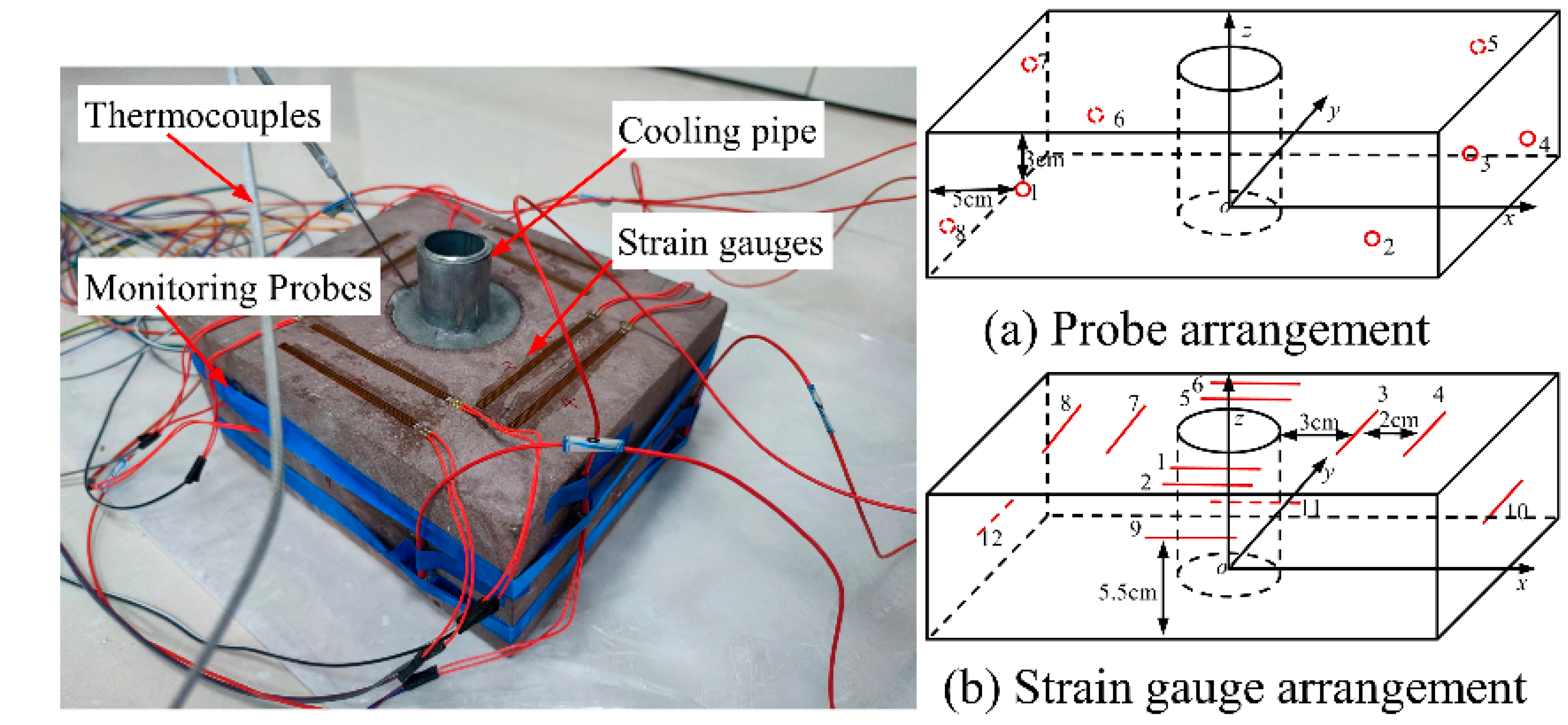
4.1. Test Scheme

Boreholes with a diameter of about 40 mm have been shown to have good crushing capacity for rocks [8,9]. Figure 8b shows that the expansion stresses of N75C2 and T40 are almost the same, the expansion reaction time is less, and the borehole diameter is larger. To test the actual crushing performance of the ICBPM on rocks and to grasp the characteristics of crushed rocks, a further static fracturing test was carried out on hard sandstone. The specimen is a purple-red sandstone from Rizhao City, Shandong Province, with a uniform and dense rock texture, a uniaxial compressive strength of 113.79 MPa, and a tensile strength of 4.34 MPa. In the actual environment, the distance of the free surface from the center of the borehole is not consistent. Therefore, the rectangular specimen was designed with a length, width, and height of 250 mm, 220 mm, and 110 mm, respectively. Drillholes with a 75 mm diameter and 110 mm depth were made in the center of the specimen, and the distances from the center of the drillholes to the free surface were 125 mm and 110 mm, respectively. Based on the expansion test, the model of the cooling tube is selected as C2. Acoustic emission and strain acquisition systems were deployed to monitor the damage characteristics of the specimen. Briefly, the acoustic emission monitoring system adopted the PCI-II type 8-channel acoustic emission collector, and the Nano30 sensor with a preamplifier gain of 40 dB, sampling frequency of 1 MSPS, and a threshold value of 35 dB was selected. In the case of the strain acquisition system, the DH3818 static strain gauge and BFH120-100AA concrete strain gauge were employed, with a resistance value of 120 Ω, sensitivity of 2.0, and a filament lattice dimension of 100.0 × 4.0 mm. The K-type armored thermocouple within 0–500 °C and a temperature recorder with 1 min recording intervals were adopted for temperature monitoring. The arrangement of the test’s equipment is provided in Figure 10.
With the center point of the specimen’s bottom surface as the origin, the acoustic emission probes were arranged on the diagonal lines on four side surfaces (xoz and yoz). The x, y, and z boundary directions were each moved inward by 5, 5, and 3 cm, respectively. In addition, vaseline was applied between the transducer and the specimen as a coupling agent, and adhesive tapes were used to fix the transducer. The strain gauges of the xoy plane were placed with the center of the surface as the base point. The strain gauges were pasted along the x and y directions, with a distance of 3 and 5 cm from the boundary of the borehole to the outward directions, and lateral strain gauges were arranged in the center of the plane. Thermocouples were inserted inside the slurry to record the slurry reaction temperature. After arranging the equipment, the slurry was injected into the hole at a water/cement ratio of 0.34, and water was poured into the cooling pipe following a water injection coefficient of 0.14. Then, the expansion was observed.

4.2. Cumulative Count Results and Analysis

Acoustic emission ringing count refers to the number of acoustic emission signal oscillations for a set threshold, enabling the reflection of the acoustic emission signal’s strength and frequency, and it is typically used to evaluate the strength of acoustic emission activity [33]. Figure 11 shows the fracture development and ring count characteristics of the hard sandstone specimen.
The process from slurry filling to specimen destruction can be seen in the figure above. After the filled slurry stands for a long period, the pressure inside the borehole continues to build up, and a sudden fracture occurs, emitting acoustic emission signals. In line with the acoustic emission signal and shooting time information, the development of the fracture was captured. According to the loading test with a mechanical testing machine, most of the force-triggered rock deformation will go through the processes of microfracture compaction (phase I), elastic deformation (phase II), stable fracture development and extension (phase III), and unstable extension (phase IV). The corresponding acoustic emission characteristics are as follows: For phase I, the primary fissures (in the form of pores) inside the rock are closed owing to compression, the newly created cracks are few, the acoustic emission counts increase, the energy is small, and smooth changes are observed in the cumulative count curve. In the case of phase II, the rock compression continues with linear elasticity, the number of nascent cracks attenuates inside the rock, and the acoustic emission counts and energy changes undergo a quiet period. When entering phase III, the loading reaches 60–80% of its strength, the quantity and size of new cracks inside the rock is enhanced, and the acoustic emission counts and single energy release intensify, which can be manifested by the surge in the ringing count and energy curves. In phase IV, the fissure generation accelerates, and an unstable expansion occurs until the loss of bearing capacity. Thereafter, the load exceeds the maximum strength of the rock, improving the acoustic emission ringing counts and the energy release with significant fluctuations in the corresponding curves, but these increments fail to surpass the peak values of counts and energy release.
When using acoustic emission to monitor rock damage characteristics, the initial damage occurs on the surface and inside the specimen. This produces acoustic signals that can only be translated into electrical ones using the probe and recorded with the computer. As a result, the documented data are directly proportional to the magnitude of the damage-induced acoustic signals inside the specimen. Notably, the acoustic emission signal displays hysteresis. In the uniaxial compression test, the mechanical testing machine recorded the maximum failure stress before the acoustic emission signal registered the maximum ringing count. In addition, the specimen was subjected to intense pressure and broke within minutes. In this process, a clear acoustic signal was created since the primary pores were compacted. The fractured rock is extruded and misaligned. Compared to the compaction stage, the destruction stage generates a sudden increase in acoustic signals, followed by a continuous development after the specimen is destroyed.
According to Figure 11, the fracture of the hard rock under the SCDA loading conditions is significantly different from that at the mentioned phases.
This paper explored the loading method of the SCDA, including a lengthy process of a hydration reaction and gradual expansion. Due to the hard rock materials, monitoring the acoustic emission signal from the compaction to the destruction stage is challenging. With energy accumulating within the borehole, the rock suddenly collapses, significantly increasing the acoustic signals. Given that the loading was performed within the borehole, and no constraints were applied on the outer boundary, no compression or misalignment was detected between the rock mass and the block after destruction. As a result, the generation of acoustic emission signals after rock damage was quite limited. The detectable signals originate from the rupture of primary cracks and the growth of secondary cracks. As seen in Figure 11, the ringing signals exhibit the same traits as crack formation. Before damage, the ringing count exhibits almost no acoustic signals; substantial acoustic signals suddenly appear during damage, with minor fluctuations thereafter. The acoustic emission data align with the sequence of rock fracture, primary crack, and secondary crack formation in the image. The test outcomes indicate that acoustic emission is an accurate indicator of rock fracture characteristics when exposed to SCDA expansion.

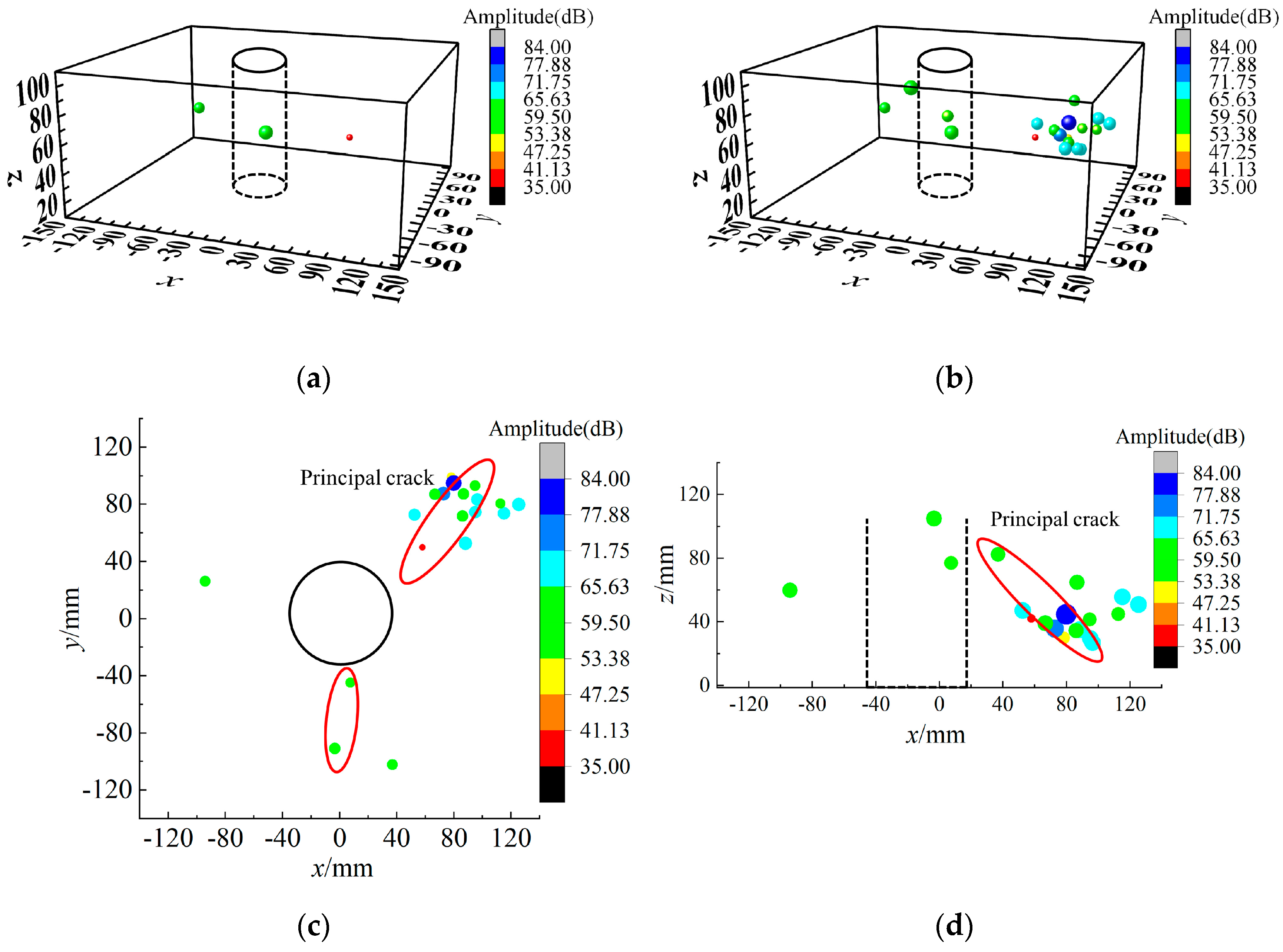
4.3. Spatial and Temporal Evolution Characteristics of the Acoustic Emission

The energy generated by the internal damage of the rock is detected by eight sensors on the specimen’s surface and is identified as an event, i.e., a localization point, through an iterative algorithm. The distribution of the localization points and energy amplitude can visually reflect the characteristics of the microfracture evolution within the rock, and rock rupture occurs under macroscopic conditions. Figure 12 displays the 3D images of the localization points from the main and top views based on the acoustic emission signals emitted when the specimen is ruptured due to the expansion of the SCDA slurry.
From this figure, relatively few events are distributed in the inner wall of the borehole at the pre-rupture phase of the specimen. Additionally, the stress distribution inside the specimen decreases with increasing distances between the stress and the center of the circle, and a closer spacing to the specimen center tolerates a higher stress. This relationship is manifested as the temporal and spatial characteristics of the fissures in the macroscopic stage, and these fissures—which are close to the center of the borehole—are the first ones to appear and gradually evolve and expand from the center when subjected to increasing SCDA stress. With the enhancing expansion pressure, the events increase suddenly upon rupture, and the range of crack occurrence remains close to the borehole wall, indicating that numerous fissures are generated near the borehole wall. The expansion stress results in stress concentration at the fissures and an outward expansion of cracks. The reason for this is that the rock undergoes brittle breakage and then circumferential expansion with the absence of circumferential pressure and constraints. As a result, the acoustic emission events generated by the fracture penetration away from the center of the borehole wall are characterized by an overall low number of events and high-energy individual events.

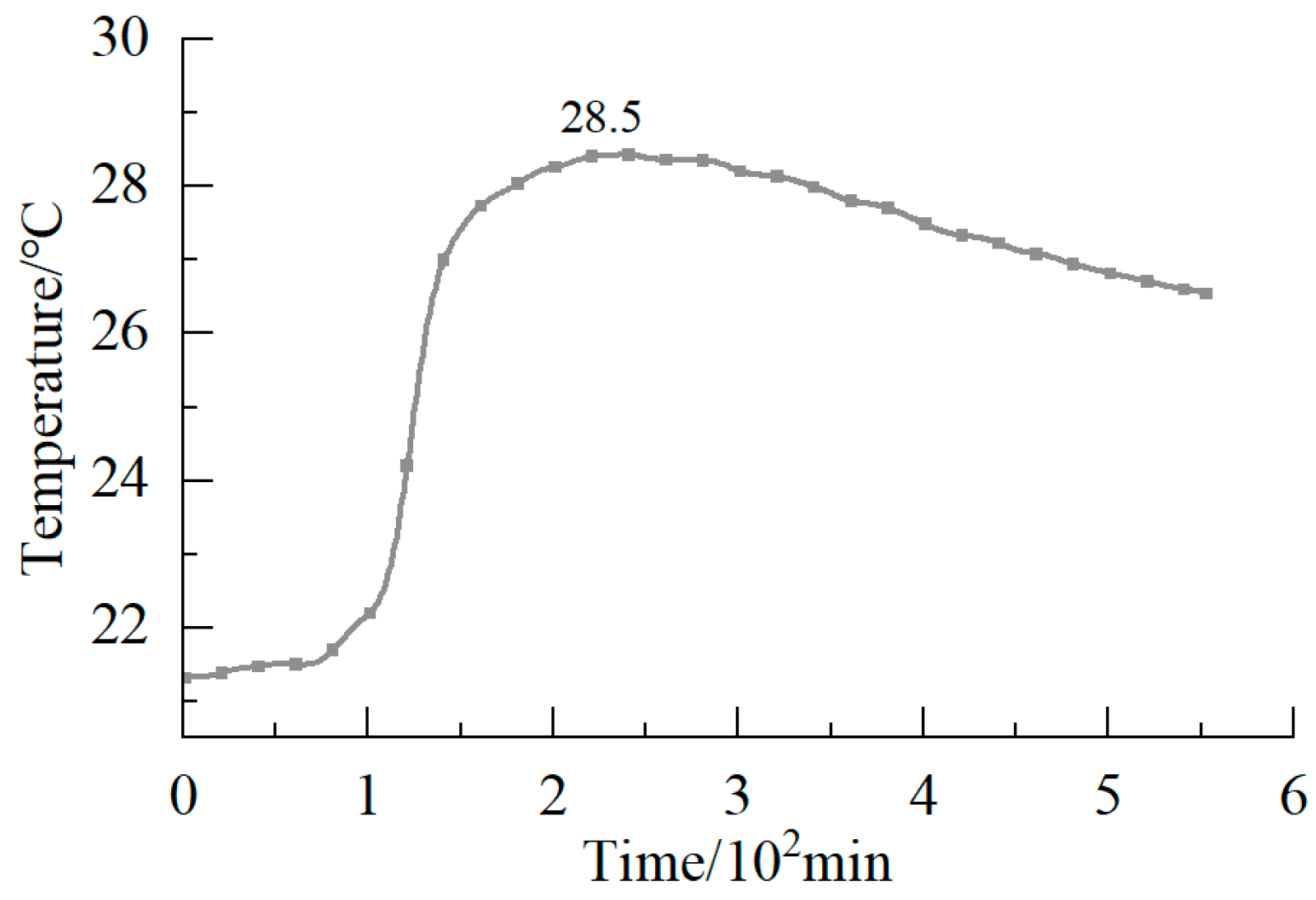
4.4. Temperature and Strain Monitoring Results and Analysis

Strain gauges were placed randomly to monitor rock deformation and crack expansion. In this paper, strain gauges with long grids were arranged closely along the periphery of the borehole. Using strain gauges can intuitively reflect the expansion of the SCDA and rock deformation, and the strain monitoring data are shown in Figure 13.
From the figure above, the fractured and intact surface strains were defined according to rock mass integrity. The strain values of both types show an overall linear growth trend with the increasing expansion pressure and undergo the compression density stage. The strain growth presents a concave shape at the initial stage and then enters the linear growth stage. The measurements of strain gauges on the xz and yz (9, 10, 11, and 12) sides of the specimen are higher than those on the xy plane in the same direction. The strain values of the fractured and intact surfaces of the specimens show significant variability. Considering the SCDA-generated expansion pressure in the borehole as a uniform load, the vertical distances from the center of the borehole to the fracture and intact surfaces are 11 and 12.5 cm, respectively, indicating that the strains on the fractured surface are larger than those on the intact surface, and the lateral surface exhibits the fastest strain growth. When the strain values reach 198.19 and 238.89, respectively, the brittle fracture of the test block occurs, and acoustic emission energy is generated. The fracture occurs in the specimen plane where the minimum resistance line is located. This phenomenon suggests that the minimum resistance line has a significant guiding effect, and the fracture direction of the specimen can be predicted by observing the changing trend of the strain values. It is concluded that using the minimum resistance line to orientate the fractured rock body and predict the fracture direction according to the trend of the strain value is reliable, and the reproducibility of the test results is good. Figure 14 shows the fracture results of the test blocks in the repeatability test.
The “Y”-shaped crack pattern of the specimens is different from the “†” or “T” rupture patterns of the cubic specimen after failure. In addition, the cracks all appear in the free plane where the minimum line of resistance is located, indicating that the minimum line of resistance significantly influences the cracks of the specimens and has significant directionality.
Figure 15 shows the temperature variation of the SCDA during rock fracture.
As shown in Figure 15, the temperature profile of the SCDA reveals the development of expansion stress. The temperature rise time is consistent with the tested results in the steel pipe, indicating a consistency in the initial solidification time of the SCDA under the same ambient temperature conditions. The dosage change has few effects on the curing time of the SCDA, ensuring abundant construction time. Under the same condition of water injection, the temperature inside the specimen is significantly reduced compared to that inside the steel pipe. This is mainly due to the test condition of the steel pipe, where the outside of the steel pipe is air. Notably, the air is recognized as a poor heat conductor, possessing a thermal conductivity coefficient of 0.01–0.04 W/m·K and a specific heat capacity of 1003 J/ kg·K. In contrast, the coefficient of thermal conductivity and the specific heat capacity of the rock are 2–6 W/m·K and 700–1000 J/ kg·K, respectively [34,35]. Air exhibits a poorer ability to absorb and transfer heat than the rock, thus leading to a better heat insulation effect and less heat dissipation. As a result, the test temperature of the SCDA in the rock is further reduced.

5. Discussion

5.1. Influence of Injection Volume on Expansion Properties

Borehole diameter affects the charge in the expansion stress. According to Figure 8a, the expansion stress in the water bath increases with the elevating borehole diameter when the slurry filling height is the same.
However, in the actual working environment, the heat generated from the hydration reaction significantly impacts the expansion performance and crushing effect. When using the ICBPM to test the expansion stress, the change in the cooling pipe diameter affects the water injection volume and slurry content. In this paper, the water injection coefficient was considered to reveal the relationship among the water injection volume, slurry content, reaction temperature, and expansion stress, and it is shown in Equation (9) as follows:
k = ρ 1 r 1 2 h 1 ρ 2 ( R 2 r 2 2 ) h 2
where k is the water injection coefficient; ρ 1 stands for the water density, 1 g · cm 3 ; ρ 2 is the slurry density, and taken as 2.25 g · cm 3 when the water/cement ratio is 0.34; h 1 and h 2 are the heights of the water injection and the drilled hole, respectively; r 1 and r 2 represent the inner and outer diameters of the cooling tube, respectively; and R represents the diameter of the drilled hole.
Above all, the expansion performance and blowhole prevention effect of the ICBPM are related to the water injection coefficient. The relationship between the water injection coefficient and between the changes in the temperature and expansion pressure is illustrated in Figure 16.
The water injection coefficient has a linear decreasing relationship with temperature. Specifically, the higher water injection coefficient indicates that more water is injected, which causes less slurry content and heat release, resulting in a better effect of spray prevention. However, the increasing water injection will expand the diameter or length of the cooling pipe and reduce the SCDA content, thus affecting the construction efficiency and crushing effect. The effect of the water injection coefficient on the effect of blowhole prevention was further analyzed. Experimental data show that when the water injection coefficient is 0.14, the hydration reaction temperature is 85.8 °C, and the effect of blowhole prevention is improved at the maximum expansion stress. When ICBPM tests were conducted, the heat increased with increasing charge. As mentioned earlier, the heat released from the full reaction of 1 kg of SCDA can raise 2.8 kg of water from 20 to 100 °C with a water injection coefficient of about 2.1. The results show that the actual water injection coefficient is much less than 2.1 since the heat generated from the hydration reaction is lower than that in the early stage of the reaction. The cooling water delivers a blowhole-preventing effect in the initial hydration reaction. However, during the later reaction period, the expansion pressure inside the slurry rises, the reaction-generated heat is absorbed by Ca(OH)2, and its temperature increases, yet no new blowholes are formed. Thus, a reduced water injection coefficient can be used to prevent the blowholes, and the blowhole prevention mechanism is further verified.

5.2. Effect of Pore Size on the Ability to Break Rock

SCDAs are commonly used in engineering with 40–50 mm hole diameters. Despite their popularity, they have limitations. For one thing, they cannot be applied in large-diameter drillholes due to the blowholes that are formed; moreover, the engineering efficiency is limited by their long reaction time. The adoption of the ICBPM can address the above problems well. In addition to the remarkable reduction in the expansion reaction time, it exhibits a good blowout prevention performance, permitting the exponential expansion of the hole’s diameter to improve the adaptability to different construction equipment and engineering environments. Figure 17 shows the expansion performance of 40 mm and 75 mm drillholes under two test environments.
It can be seen that the expansion stress is consistent with the two borehole diameters in both test environments, with the resulting radial expansion stress and axial stress reaching about 49 MPa and 10 MPa, respectively. The reason for this is that the heat dissipation conditions are optimized in the tank environment, achieving consistent expansion stress with that of the 40 mm borehole diameter. In the water bath, the slurry expands slowly, the reaction is more thorough, and the expansion stress curve is smoother. However, the test time is too long, and the results do not meet the expected standards. Compared with T40, N75C2 shows a steep increase in the expansion stress curve. This rise is attributed to the heat released from the hydration reaction accelerating the expansion reaction with the employment of the internal cooling method; as a result, the expansion reaction time is reduced dramatically.
The expansion stress data were fitted to obtain Equation (10) for N75C2(C) as follows:
y = 49.70 1 + e x 235.10 16.52 + 48.38
where x is the expansion action time, min; y is the expansion pressure, MPa.
Figure 8b shows the small expansion stress fluctuation of the ICBPM, which indicates the equation’s high generation, reflecting the development law of expansion stress over time.
In addition to the drastic reduction in reaction time, the hole size also largely impacts the crushing of the rock. The rock exhibits much lower tensile strength than compressive strength [36,37,38]. A good crushing effect of a 40 mm borehole on the rock was confirmed, and further increasing the borehole diameter with the ICBPM remarkably improves the performance of the SCDA for crushing it.
It is assumed that the inner and outer walls of the borehole are subjected to uniformly distributed pressure during the expansion of the SCDA, and the expanded borehole can be regarded as an axisymmetric model. According to the thick-walled cylinder theory of elastic mechanics, in the case of the outer wall pressure P2 = 0, the distribution of tensile stress at a specific point inside the specimen is modeled as Equation (11) as follows:
σ φ = a 2 P 1 b 2 a 2 1 + b 2 ρ 2
where σ φ is the tensile stress, MPa; a is the inner borehole diameter, mm; b is the outer diameter, mm; P 1 is the expansion pressure inside the borehole, MPa; and ρ is the distance from the internal test block to the borehole center, mm.
Taking the inner diameter a = 40 mm as an example, the distribution of tensile stress at a distance ρ from the middle of the circular hole with the increasing hole diameter is shown in Figure 18.
It can be observed that the stress state at an internal block point decreases nonlinearly with the increasing distance to the borehole’s center. This decreasing trend is consistent for different borehole diameters due to the power function of variations in tensile stress within the test block with ρ. It is also noted that the tensile stresses applied inside the block show significant differences depending on the diameters of the hole. To further analyze the effect of the diameter of a borehole on rock-crushing performance, Equation (12) shows the effect of an enlarged pore size on the expansion properties under the same boundary conditions.
m = σ φ 2 σ φ 1 = l 2 0.0025 b 2 1 0.0025 b 2 l 2
where m denotes the expansion performance enhancement factor; σ φ 1 and σ φ 2 represent the tensile stress of the specimens with different hole diameters, respectively; l = a 2 a 1 , a 1 , and a 2 refer to the different aperture diameters, a 2 > a 1 ; and b signifies the outer diameter of the drilled hole.
The crushing performance enhancement curve is outlined in Figure 19, according to Equation (12).
The coefficient of influence between the pore size and crushing performance exhibits a nonlinear upward trend. The reason for this is that enlarging the hole diameter affects the borehole stress distribution and narrows the minimum line of resistance, resulting in a nonlinear increase. In summary, an increase in borehole diameter with the ICBPM is important for reducing the reaction time, improving the crushing performance, and enhancing the engineering efficiency.

6. Conclusions

The ICBPM was employed to prevent blowhole generation, and the effectiveness of this approach was verified. The effect of different cooling tube diameters on expansion performance was studied. Hard sandstone specimens were selected for fracture tests, and rupture characteristics were monitored using thermocouples, acoustic emissions, and strain collection methods. The following conclusions were drawn:
(1)
The ICBPM displays a good anti-blowout effect and favorable expansion performance. The water injection coefficient is introduced to evaluate the expansion performance of the cooling method. When the coefficient is 0.14, the blowhole prevention effect and the expansion performance are improved, and the expansion pressure is 49.0 MPa, which is considered eligible for rock-crushing operations.
(2)
The fracture test verified the rock-crushing performance of the ICBPM. The minimum line of resistance significantly influences the direction of fracture extension, and all fractures appear in the free surface at the location of the minimum line of resistance. The fracture pattern shows a Y-shape distribution, and the fracture direction can be effectively identified using the strain monitoring method. The results are insightful for the directional fracturing of rock.
(3)
The application of the ICBPM largely reduces the expansion reaction time, and increasing the pore size exponentially increases its rock-crushing performance. In addition, the experimental environment reflects appropriate engineering conditions. Considering these advantages, this method has great engineering significance.

Author Contributions

Conceptualization, R.Y. and Z.D.; methodology, J.W.; investigation, J.W., S.X. and J.D.; writing—original draft preparation, J.W.; writing—review and editing, R.Y. and Z.D.; project administration, J.W.; funding acquisition, R.Y. and Z.D. All authors have read and agreed to the published version of the manuscript.

Funding

This research was financially supported by the National Natural Science Foundation of China (52174109); the Program for Innovative Research Team (in Science and Technology) at the University of Henan Province (22IRTSTHN005); and the Henan Provincial Science and Technology Research Project (222102320271).

Data Availability Statement

The data used to support the findings of this study are included within this article.

Conflicts of Interest

The authors declare no potential conflicts of interest concerning the research, authorship, and/or publication of this article.

References

  1. Cho, H.; Nam, Y.; Kim, K.; Lee, J.; Sohn, D. Numerical simulations of crack path control using soundless chemical demolition agents and estimation of required pressure for plain concrete demolition. Mater. Struct. 2018, 51, 169. [Google Scholar] [CrossRef]
  2. Shang, J.; Zhao, Z.; Aliyu, M.M. Stresses induced by a demolition agent in non-explosive rock fracturing. Int. J. Rock Mech. Min. 2018, 107, 172–180. [Google Scholar] [CrossRef]
  3. Natanzi, A.S.; Laefer, D.F.; Zolanvari, S.M.I. Selective demolition of masonry unit walls with a soundless chemical demolition agent. Constr. Build. Mater. 2020, 248, 118635. [Google Scholar] [CrossRef]
  4. Zheng, W.Z.; Li, R.S.; Xu, L.B.; Hou, X.M. Review and analysis on research and application of static crushing technology. J. Harbin Inst. Technol. 2021, 53, 190–200. [Google Scholar] [CrossRef]
  5. Gambatese, J.A. Controlled Concrete Demolition Using Expansive Cracking Agents. J. Constr. Eng. Manag. 2003, 129, 98–104. [Google Scholar] [CrossRef]
  6. De Silva, V.R.S.; Ranjith, P.G. A study of rock joint influence on rock fracturing using a static fracture stimulation method. J. Mech. Phys. Solids 2020, 137, 103817. [Google Scholar] [CrossRef]
  7. Xu, S.; Hou, P.; Li, R.; Cai, M. An Experimental Study on the Mechanical Properties and Expansion Characteristics of a Novel Self-Swelling Cartridge for Rock Breakage. Rock Mech. Rock Eng. 2021, 54, 819–832. [Google Scholar] [CrossRef]
  8. Arshadnejad, S. Design of hole pattern in static rock fracture process due to expansion pressure. Int. J. Rock Mech. Min. 2019, 123, 104100. [Google Scholar] [CrossRef]
  9. Xu, J.Z.; Zhai, C.; Ranjith, P.G.; Sun, Y.; Qin, L.; Ma, H.T.; Guo, J.; Ma, Z. Investigation of non-explosive expansion material in roof caving field application. Int. J. Rock Mech. Min. 2019, 120, 50–57. [Google Scholar] [CrossRef]
  10. Wang, S.; Mitri, H.; Li, H.; Li, D.; Wang, W. Study of SCA-Induced Rock Crack Propagation under Different Stress Conditions Using a Modified Cohesive Element Method. Adv. Civ. Eng. 2018, 2018, 7936043. [Google Scholar] [CrossRef]
  11. Wang, Z.; Fu, X.; Pan, J.; Deng, Z. Effect of N2/CO2 injection and alternate injection on volume swelling/shrinkage strain of coal. Energy 2023, 275, 127377. [Google Scholar] [CrossRef]
  12. Yang, S.; Yang, Z.; Zhang, P.; Tian, W. Experiment and peridynamic simulation on cracking behavior of red sandstone containing a single non-straight fissure under uniaxial compression. Theor. Appl. Fract. Mech. 2020, 108, 102637. [Google Scholar] [CrossRef]
  13. Liu, T.; Lin, B.; Yang, W. Mechanical behavior and failure mechanism of pre-cracked specimen under uniaxial compression. Tectonophysics 2017, 712–713, 330–343. [Google Scholar] [CrossRef]
  14. De Silva, R.; Pathegama Gamage, R.; Anne Perera, M. An Alternative to Conventional Rock Fragmentation Methods Using SCDA: A Review. Energies 2016, 9, 958. [Google Scholar] [CrossRef]
  15. Manatunga, U.I.; Ranjith, P.G.; De Silva, V.R.S.; Wanniarachchi, W.A.M. Modified non-explosive expansive cement for preconditioning deep host rocks: A review. Geomech. Geophys. Geo-Energy Geo-Resour. 2021, 7, 99. [Google Scholar] [CrossRef]
  16. Laefer, D.F.; Ambrozevitch-Cooper, N.; Huynh, M.P.; Midgette, J.; Ceribasi, S.; Wortman, J. Expansive fracture agent behaviour for concrete cracking. Mag. Concr. Res. 2010, 62, 443–452. [Google Scholar] [CrossRef]
  17. Xu, S.; Hou, P.Y.; Li, R.R.; Suorineni, F.T. An improved outer pipe method for expansive pressure measurement of static cracking agents. Int. J. Min. Sci. Technol. 2022, 32, 27–39. [Google Scholar] [CrossRef]
  18. Dai, L.L.; Li, Q.N. Study of Expansion Pressure Determining of Static Crushing Agent. J. Wuhan Univ. Technol. 1989, 11, 131–135. [Google Scholar]
  19. Wang, Y.J.; Tian, X.B. Study on Method of Static Cracking Agent Pressure Measurement. Explos. Mater. 2004, 47, 1–3. [Google Scholar]
  20. Dai, X.H.; Qiu, Z.G.; Zhang, F.P.; Xu, X.X. Experimental Study on a New Swelling Pressure Measuring Method of the Static Cracking Agent. Met. Mine 2015, 50, 153–156. [Google Scholar]
  21. Dai, X.H.; Zhang, F.P.; Qiu, Z.G.; Xu, X.X. Experimental Study on Axial Swelling Mechanical Properties of Static Cracking Agent. J. Northeast. Univ. (Nat. Sci.) 2016, 37, 248–252. [Google Scholar]
  22. Qiu, Z.G.; Ji, Y.; Zhang, F.P.; Yan, G.L. Experimental Investigation and Numerical Modeling of Elastic Modulus Variation with Stress during Hydration and Expansion Process of Static Cracking Agent. Appl. Sci. 2021, 11, 3955. [Google Scholar] [CrossRef]
  23. Xu, J.Z.; Zhai, C.; Qin, L.; Yu, G.Q. Evaluation research of the fracturing capacity of non-explosive expansion material applied to coal-seam roof rock. Int. J. Rock Mech. Min. 2017, 94, 103–111. [Google Scholar] [CrossRef]
  24. Natanzi, A.S.; Laefer, D.F.; Connolly, L. Cold and moderate ambient temperatures effects on expansive pressure development in soundless chemical demolition agents. Constr. Build. Mater. 2016, 110, 117–127. [Google Scholar] [CrossRef]
  25. Xie, B.J.; Yan, Z.; Zhao, Z.M. Experimental study on anti-spraying hole of static blasting based on physical cooling. J. Saf. Sci. Technol. 2018, 14, 150–154. [Google Scholar] [CrossRef]
  26. De Silva, V.R.S.; Ranjith, P.G.; Perera, M.S.A.; Wu, B.; Rathnaweera, T.D. The Influence of Admixtures on the Hydration Process of Soundless Cracking Demolition Agents (SCDA) for Fragmentation of Saturated Deep Geological Reservoir Rock Formations. Rock Mech. Rock Eng. 2019, 52, 435–454. [Google Scholar] [CrossRef]
  27. Chen, W.D.; Wu, P.W.; Yu, H.J.; Xu, G.Q.; Sun, H.Y.; Li, X.L.; Tai, H.Y. Spray-prevention trial and rock-breaking simulation of a static cracking agent. J. Harbin Eng. Univ. 2021, 42, 1295–1302. [Google Scholar] [CrossRef]
  28. Gholinejad, M.; Arshadnejad, S. An experimental approach to determine the hole-pressure under expansion load. J. S. Afr. Inst. Min. Metall. 2012, 112, 631–635. [Google Scholar]
  29. Li, R.S.; Yan, Y.; Jiang, Z.S.; Zheng, W.Z.; Li, G.C. Impact of hole parameters and surrounding constraint on the expansive pressure distribution and development in soundless chemical demolition agents. Constr. Build. Mater. 2021, 307, 124992. [Google Scholar] [CrossRef]
  30. Laefer, D.F.; Natanzi, A.S.; Zolanvari, S.M.I. Impact of thermal transfer on hydration heat of a Soundless Chemical Demolition Agent. Constr. Build. Mater. 2018, 187, 348–359. [Google Scholar] [CrossRef]
  31. Xu, S.; Yang, Z.M.; Cai, M.; Hou, P.Y. An experimental study on the anchoring characteristics of an innovative self-swelling Split-set. Tunn. Undergr. Space Technol. 2021, 112, 103919. [Google Scholar] [CrossRef]
  32. Arshadnejad, S.; Goshtasbi, K. Analysis of the radial and tangential stress distribution between two neighbouring circular holes under internal pressure by numerical modelling. J. S. Afr. Inst. Min. Metall. 2011, 111, 301–308. [Google Scholar]
  33. Zhao, K.; Song, L.; Zeng, P.; Xie, W.J.; Gong, C.; Wu, W.K.; Liu, Y. Experimental Study on Failure Process and Precursor Characteristic Acoustic Emission of Filling Body-Sandstone Combination under Uniaxial Compression. Met. Mine 2022, 57, 70–76. [Google Scholar] [CrossRef]
  34. Lin, M.Z. Petrophysics and Its Engineering Applications; Chongqing University Press: Chongqing, China, 1991. [Google Scholar]
  35. Kobranova, B.H.; Lepalskaya, H. Determination of Physical Properties of Rocks; Beijing Geology Publishing House: Beijing, China, 1959. [Google Scholar]
  36. Chen, L.; Guo, W.; Zhang, D.; Zhao, T. Experimental study on the influence of prefabricated fissure size on the directional propagation law of rock type-I crack. Int. J. Rock Mech. Min. 2022, 160, 105274. [Google Scholar] [CrossRef]
  37. Li, D.; Zhu, Q.; Zhou, Z.; Li, X.; Ranjith, P.G. Fracture analysis of marble specimens with a hole under uniaxial compression by digital image correlation. Eng. Fract. Mech. 2017, 183, 109–124. [Google Scholar] [CrossRef]
  38. Basu, A.; Mishra, D.A.; Roychowdhury, K. Rock failure modes under uniaxial compression, Brazilian, and point load tests. Bull. Eng. Geol. Environ. 2013, 72, 457–475. [Google Scholar] [CrossRef]
Figure 1. Characteristics of SCDA blowholes.
Processes 12 00336 g001
Figure 2. Characteristics of blowholes under sealed condition.
Processes 12 00336 g002
Figure 3. Temperature characteristics of the hydration reaction at the time of borehole blowing.
Processes 12 00336 g003
Figure 4. Expansion mechanism of SCDA hydration reaction.
Processes 12 00336 g004
Figure 5. Effect of ICBPM blowhole prevention test.
Processes 12 00336 g005
Figure 6. Schematic diagram of the design of the expansion performance test equipment and sensors.
Processes 12 00336 g006
Figure 7. Macroscopic effect of SCDA expansion. (a) Macroscopic effects of expansion in a constant-temperature water bath. (b) Macro effects of ICBPM expansion.
Processes 12 00336 g007
Figure 8. Expansion performance parameters. (a) Expansion stress in constant-temperature water bath. (b) Expansion stress of ICBPM.
Processes 12 00336 g008
Figure 9. Temperature profiles of SCDA hydration reaction.
Processes 12 00336 g009
Figure 10. Equipment arrangement.
Processes 12 00336 g010
Figure 11. Ring count and fracture development characteristics.
Processes 12 00336 g011
Figure 12. Acoustic emission localization characteristics. (a) Event locus 1 min before macro rupture. (b) Macro fracture event locators. (c) Top view of event locations. (d) Main view of event locations.
Processes 12 00336 g012
Figure 13. Strain–time curves.
Processes 12 00336 g013
Figure 14. Final fracture morphologies of the two specimens.
Processes 12 00336 g014
Figure 15. Temperature–time curve.
Processes 12 00336 g015
Figure 16. Coefficient of water injection concerning temperature and expansion stress.
Processes 12 00336 g016
Figure 17. Comparison of the expansion performance of 40 mm and 75 mm drillholes.
Processes 12 00336 g017
Figure 18. Tensile stress distribution in the test block with different hole diameters.
Processes 12 00336 g018
Figure 19. Effect of enlarged borehole on crushing performance.
Processes 12 00336 g019
Table 1. Parameters of ICBPM blowhole prevention test.
NameOuter Diameter/mmInner Diameter/mmWater/cement ratioFilling Height/mm
Cooling pipe5.622.33/1000.00
Testing steel pipes75.531.310.341000.00
Table 2. Test parameters for expansion performance of ICBPM.
Serial NumberInner Diameter/mmOuter Diameter/mmCooling Pipe Inner Diameter/mmCooling Pipe Outer Diameter/mmFilling Height/mm
T404048///
T757590///
T75C37590///
N75C175902126500
N75C275903642500
N75C375903947500
Disclaimer/Publisher’s Note: The statements, opinions and data contained in all publications are solely those of the individual author(s) and contributor(s) and not of MDPI and/or the editor(s). MDPI and/or the editor(s) disclaim responsibility for any injury to people or property resulting from any ideas, methods, instructions or products referred to in the content.

