Article

Influence of Mining Sequence of Branch on Stope Pressure Behaviour on Continuous Mining and Continuous Backfilling

1
School of Civil and Resource Engineering, University of Science and Technology Beijing, Beijing 100083, China
2
School of Civil Engineering, North China University of Technology, Beijing 100144, China
*
Author to whom correspondence should be addressed.
Processes 2024, 12(3), 442; https://doi.org/10.3390/pr12030442
Submission received: 25 January 2024 / Revised: 19 February 2024 / Accepted: 20 February 2024 / Published: 22 February 2024

Abstract

:
Instability in coal pillars and filling bodies is a common occurrence during the mining process of continuous mining and continuous backfilling (CMCB). In view of this, combining numerical simulation, similarity simulation, and on-site testing approaches, backfill mining models were established in Flac3d5.01 software, similarity model test bench, and “two-stage”, “three-stage”, and “four-stage” mining sequences were conducted; the stress characteristics of coal pillar-filling body and the displacement evolution law of surrounding rock have been compared under three typical mining sequences. The results show that compared to two-stage mining sequence, three-stage and four-stage mining sequences provide sufficient time for the solidification of the filling body. The coal pillar exhibits better stability in the early stage of mining, but the stress concentration phenomenon is more significant in the later stage of mining. The stress concentration coefficient is the highest when the width of the coal pillar is 10 m. The integrity of the overburden is intact in different mining sequences, with only a small amount of separation and longitudinal cracks. Increasing the number of mining stages significantly reduces the roof subsidence, with the maximum roof subsidence in the three- and four-stage mining sequences being only 62.0% and 33.9% of that in the two-stage mining sequence. “Two stages”, “three stages”, and “four stages” of mining sequences are implemented in response to the requirements of weak and thick coal seam mining in Haoyuan Coal Mine and gangue disposal in Chahasu Coal Mine. Good engineering applications are achieved, enabling the realisation of safe, green, and efficient coal mining.

1. Introduction

The coal mining sector in China is currently plagued by several challenges, such as environmental protection, resource depletion, and gangue disposal [1,2,3,4]. As a green mining method, continuous mining and continuous backfilling (CMCB) technology can solve the problems at the root [5,6]. In 2017, this technology—which has the advantages of low technological threshold, flexible layouts for working face, minimal initial investment cost, parallel mining, and filling rate—solved the problem of pressed coal resource recovery beneath the eco-park in Yuxing Mine, Inner Mongolia [7,8]. Numerous scholars have conducted studies on different aspects of this technology, including filling equipment and process [9], filling materials and pipeline conveying [10,11,12,13,14], quarry overburden movement law [15,16], and coal pillar-filling body stability [17,18,19]. These studies have further encouraged the on-site application of this technology.
As a type of roadway mining method, the mining process of CMCB has the characteristics of “multi-circulation, small perturbation” [20,21,22,23]. A large number of coal pillar groups are formed during this mining process. When mining disturbances occur, the stability of these coal pillars gradually declines, which may lead to a large-scale instability of the coal pillar groups and compromise the safety of back mining. A reasonable branching sequence is a prerequisite for optimising the parameters and safe mining of CMCB. However, there is a major lack of research in this area. Generally, the mining sequence is optimised by designing many practical ways and then using similarity simulation, numerical simulation, and on-site monitoring to establish comparisons and preferences. Ye et al. [24] investigated the mining technique of gently inclined multi-layer deposits using similarity simulation experiments to evaluate the mine pressure manifestation law of the quarry under two types of back mining sequences, forward and backward mining. Li et al. [25] investigated the instability mechanism of floor dynamic pressure roadway in the adjacent layers of the coal seam group under different mining sequences and proposed the adoption of downstream mining to minimise multiple mining operations on the roadway. Wang et al. [26] summarised the impact ground pressure manifestation law and its influencing factors as affected by the mining layout, providing a theoretical basis for impact ground pressure prevention and control. Hu et al. [27] developed five alternative simulation schemes for deep mine section back-mining based on the time-varying parameter evolution law of rock mechanics and obtained stress and deformation characteristics of mining rock at different mining stages. The research of the above scholars has promoted the development of coal mine mining, but in the field of CMCB, there is a lack of research on the reasonable sequence of branch mining and backfilling. Mining companies generally use empirical or engineering analogy methods in the design of CMCB mining.
The branch mining of CMCB is a continuous change process of surrounding rock stress and deformation, and different mining sequences have different disturbance characteristics to the coal pillar, filling body, and overburden. Based on this, this study investigates the manifestation law of mine pressure in the quarry under different mining sequences, with a particular emphasis on analysing the force characteristics of coal pillars and filling bodies as well as the movement law of the overburden. The branch mining sequence that is most suited for a particular set of operating conditions is selected by comparing the stability of the roof, thus providing a theoretical basis for the safety of CMCB. Finally, the research results were successfully applied to the backfill mining of two mining areas in Inner Mongolia, achieving safe and efficient coal mining.

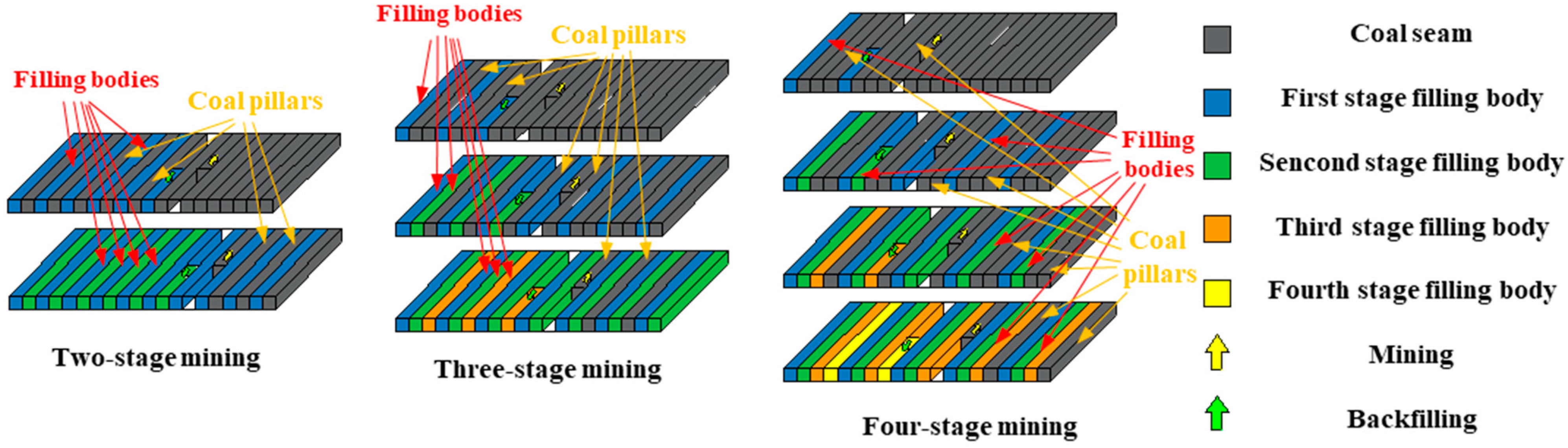
2. Branch Mining Sequence

The width of the coal pillar in one mining cycle of the CMCB working face is calculated as an integer multiple of the width of the branch. A reasonable mining sequence can reduce the stress concentration coefficient of the coal pillar and filling body, the number of branch mining cycles, and the movement distance of mining equipment; otherwise, it will not improve production efficiency. As shown in Figure 1, there are three typical mining sequences: “two-stage”; “three-stage”; and “four-stage”. Taking two-stage mining as an example, after the division of branches, coal pillars are mined and filled in every other branch, and the remaining coal pillars are used to support the overburden until the first stage of mining is completed. During the second stage of mining, the filling body serves as the support body, and the coal pillars are mined and continue to be filled until all coal resources are fully mined.
The data presented in Table 1 indicate that, as of December 2022, 36 mines in China have adopted or proposed to adopt CMCB. Of the mines in the distribution area, the majority are located in the provinces of Shandong, Shanxi, and Inner Mongolia. The number of CMCB mines in the northern part of Shaanxi Province is gradually increasing.
As can be seen from Table 1 [28,29,30], approximately 70% of CMCB mines use the “two-stage” mining sequence, while 15% of the mines individually use “three-stage” and “four-stage” mining sequences. According to the technical characteristics of short-wall mining, the majority of the branch widths are between 4 m and 6 m, with 5 m width accounting for 60% of all branch width data. According to the geological conditions of coal seams, mining companies generally use engineering analogies to choose the mining sequence. The mining operation in some mines can result in high mine pressure, which can cause phenomena such as cracking of coal pillars, filling body ganging, or bulging, as shown in Figure 2, all of which can affect mining safety and project advancement. Based on the above analysis, numerical simulation and similarity simulations are used to study the force characteristics of the coal pillar-filling body and the movement law of overburden in the CMCB mine for different sequences of back mining.

3. Numerical Simulation of Mine Pressure Manifestation Law in CMCB Mining

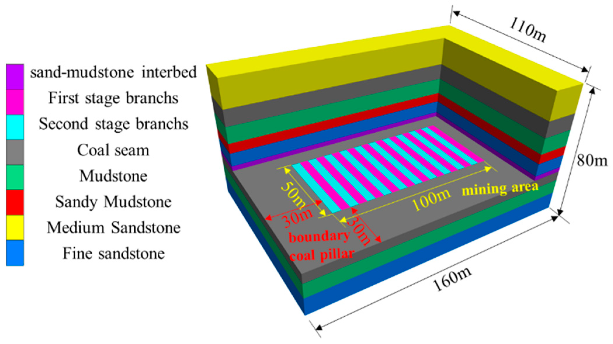
3.1. Model Establishment and Calculation

Flac3D 5.01 software is used to establish a numerical model of CMCB [31]. The computer used for model calculation is Precision T7920, with a model size of 160 m × 110 m × 80 m and a total of 457,600 elements and 477,495 nodes, as shown in Figure 3. The stress boundary condition is applied at the top instead of modelling the overburden capacity. The depth of the coal seam is 320 m, and the excavation range is 100 m × 5 m × 50 m, with a total of 20 branch lanes excavated. The immediate roof of the coal seam is a 3 m thick sand–mudstone interbed structure. The main roof is 8 m thick and comprises fine sandstone. The immediate floor is 2 m thick and comprises sandy mudstone, and the main floor is 7 m and comprises mudstone. A coal pillar of 30 m is set up in the model. The Mohr–Coulomb model is suitable for simulating various rock materials and has been widely used in the field of coal mining, so the Mohr–Coulomb model is used to model the geo-materials, and the physical and mechanical parameters of each rock strata are listed in Table 2 [32]. After the model is established, it is simulated for the initial stress condition until equilibrium is reached, and the bearing characteristics of the coal pillar-filling body and the stress distribution pattern of the surrounding rock in the quarry under “two-stage”, “three-stage”, and “four-stage” mining sequences are investigated, respectively.

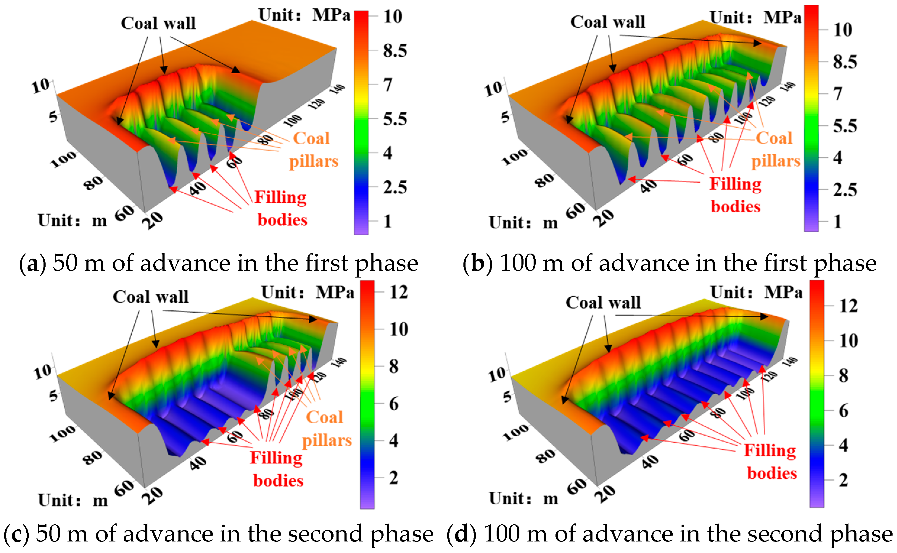
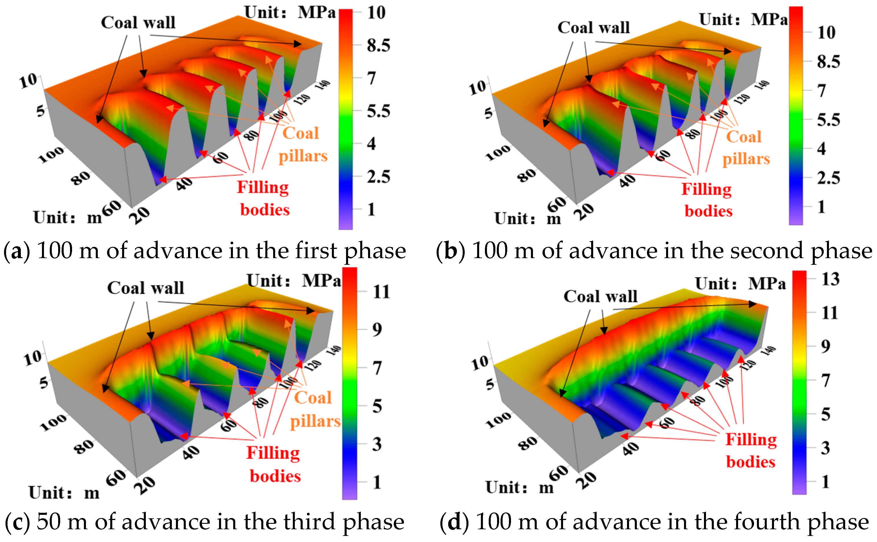
3.2. Bearing Characteristics of Coal Pillar-Filling Body under Different Mining Sequences

Considering the symmetry of the model along the plane running in the working face advancing direction, the model is cut along the said plane. The half model is then simulated to study the change rule of vertical stress in the coal pillar-filling body and the coal wall of the working face during mining.
Figure 4 shows the three-dimensional mining stress field distribution in the coal pillar-filling body under a two-stage mining sequence. It can be seen that the maximum stress in the coal pillar and filling body after the first stage of mining is 7.87 MPa and 2.56 MPa, respectively. The maximum stress in the advance abutment is 9.10 MPa, while that in the lateral abutment is 11.05 MPa. Due to the large number of branches in the first stage of mining and the width of the coal pillar being only 5 m, the bearing capacity of the coal pillar is insufficient. The coal wall surrounding the working face and the coal pillar bear the majority of the roof load. The filling body has a certain initial support capacity and provides lateral support to the coal pillar. In the second stage of mining, the coal pillar is gradually replaced by the filling body, which becomes the main load bearer. Once all of the coal pillars have been mined, the maximum stress of the filling body reaches 3.62 MPa. The maximum advance abutment stress is 10.83 MPa, and the lateral abutment pressure of the working face is 13.52 MPa.
Figure 5 shows the distribution of the three-dimensional mining stress field in the coal pillar-filling body during a three-stage mining sequence. It can be seen from the figure that after the first stage of mining, the maximum stress of the coal pillar and filling body reaches 10.50 MPa and 1.76 MPa, respectively. On the other hand, the advance abutment stress is 8.70 MPa, and the lateral abutment stress is 9.59 MPa. At this stage, the width of the coal pillar is 10 m, and the roof load is mainly borne by the coal pillar. In the second stage of mining, the width of the coal pillar is reduced to 5 m, and the roof load gradually transitions to the joint bearing of the coal pillar and the filling body. The maximum stress in the coal pillar and the filling body is 9.24 MPa and 3.52 MPa, respectively, whereas the advance abutment stress is 9.98 MPa, and the lateral abutment stress is 12.46 MPa, indicating a significant rise in stress. After the third stage of mining, the maximum stress in the filling body increases to 4.02 MPa, while the advancing abutment stress becomes 10.98 MPa, and the lateral abutment stress becomes 13.75 MPa.
Figure 6 shows the distribution of the three-dimensional mining stress field in the coal pillar-filling body under a four-stage mining sequence. It can be seen that the maximum stresses of the coal pillar after the first and second stages of mining are 10.12 MPa and 12.03 MPa. The maximum stresses in the filling body are 0.92 MPa and 2.1 MPa; the advance abutment stresses are 8.13 MPa and 9.25 MPa, and the lateral abutment stresses are 9.12 MPa and 10.31 MPa. In the first two stages of mining, the stresses in the coal pillar are greater than the lateral abutment stress and the advancing abutment stress. The width of the coal pillar is 10 m–15 m, and the roof load is mainly borne by the coal pillar. After the third phase of mining, the width of the coal pillar is 5 m, and the roof load is shifted to the filling body and the surrounding coal. The maximum stress of the coal pillar and filling body decreases to 9.52 MPa and 4.56 MPa, respectively. The advance abutment stress is 10.01 MPa, and the lateral abutment stress increases 12.57 MPa. At this stage, the lateral abutment stress is higher than the advancing abutment stress and the stress of the coal pillar. After the fourth stage of mining, all the coal pillars are mined out, and the roof load is gradually transitioned to the filling body, with a maximum stress of 4.82 MPa in the filling body. The stress is distributed in cycle fluctuation due to the enrichment rate of the filling body in each stage and the curing time; the maximum stress of the filling body in the second stage is 4.83 MPa, and the maximum stress of the filling body in the fourth stage is 1.02 MPa.
Figure 7 shows the maximum vertical stresses in different parts of the working face for different mining sequences. In contrast to three- and four-stage mining, two-stage mining has a wider disturbance range, a narrower coal pillar width of only 5 m, and a limited lateral support capacity of the coal pillar due to insufficient time for the maintenance of the filling body. Therefore, it is necessary to pay attention to its stability during the mining. In the third and fourth stages of mining, 10 m–15 m wide coal pillars with higher stability are left in the early stage, and multi-stage mining allows for enough time for the solidification of the filling body. When the width of the coal pillar is 10 m, the stress concentration coefficient of the coal pillar is the highest. However, in the later stage of mining, the stress of the coal pillar is considerably higher than that of the two-stage mining. So, it is necessary to strengthen the control of the coal ribs in the deeply buried or soft coal seams to prevent the destabilisation and destruction of the coal ribs. Regardless of the mining sequence, the stress in the filling body and the coal wall around the face increases with the increase in the number of mining steps. The filling body progressively replaces the coal pillar, which bears the majority of the roof load, until the coal pillar is completely removed. When the working face is fully mined, the filling body stress in the early stage is greater than that in the later stage. The more the steps of mining, the greater the peak stress of the filling body and the difference between the stresses in each stage. Under the condition of meeting the requirements of rock control, the strength of the filling body in the last stage can be appropriately lowered to reduce the cost of mining.

4. Similarity Simulation of the Movement Law of Overburden in CMCB

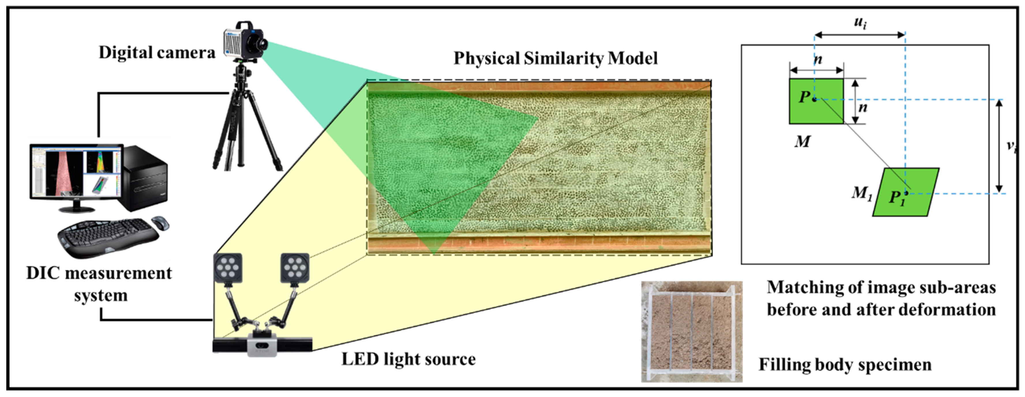
4.1. Materials and Methods

To further study the movement law of the overburden in the CMCB under different mining sequences, a similarity simulation experiment is conducted. The geometric similarity ratio of the model is 1:100; the weight similarity ratio is 1:1.6; the stress similarity ratio is 1:160, and the size of the model is 2400 mm × 20 mm × 1300 mm. The depth of the coal seam is 320 m; the height of the model is 120 m, and the remaining 200 m of the formation is modelled using heavy blocks. The materials utilised are lime, gypsum, and medium sand, and Table 3 displays the distribution of materials for the coal, strata, and filling body. This test consists of three groups: “two-stage”; “three-stage”; and “four-stage” mining. The excavation length of the model is 160 m, with a total of 32 supporting lanes. On both sides of the model, 40 m wide coal pillars are left.
The DIC measurement system shown in Figure 8 is used to measure the model displacement field. It consists of a quasi-static two-dimensional DIC system, an ordinary slow Charge Coupled Device(CCD) camera, and a Light-Emitting Diode (LED) light source. The full-field displacement of the model surface is obtained by making an inhomogeneous scattering speckle to track its movement, assuming that there is a feature point P(x,y) within the model. The size of its sub-area is M, and the size of the M pixel is n × n. When the area produces a displacement, the feature point P(x,y) becomes P1(x,y), with the distance between P(x,y) and P1(x,y) as the displacement, and the sub-region becomes M1. The correlation constant C indicates the degree of matching between P(x,y) and P1(x,y), which is solved as shown in Equation (1) [33,34]. The camera resolution is 3384 × 2704, and the model size is 2400 mm × 1200 mm. The size of the scattering size is 3 mm × 3 mm.
C = 1 P x , y P 1 x , y P 2 x , y P 1 2 x , y 1 / 2

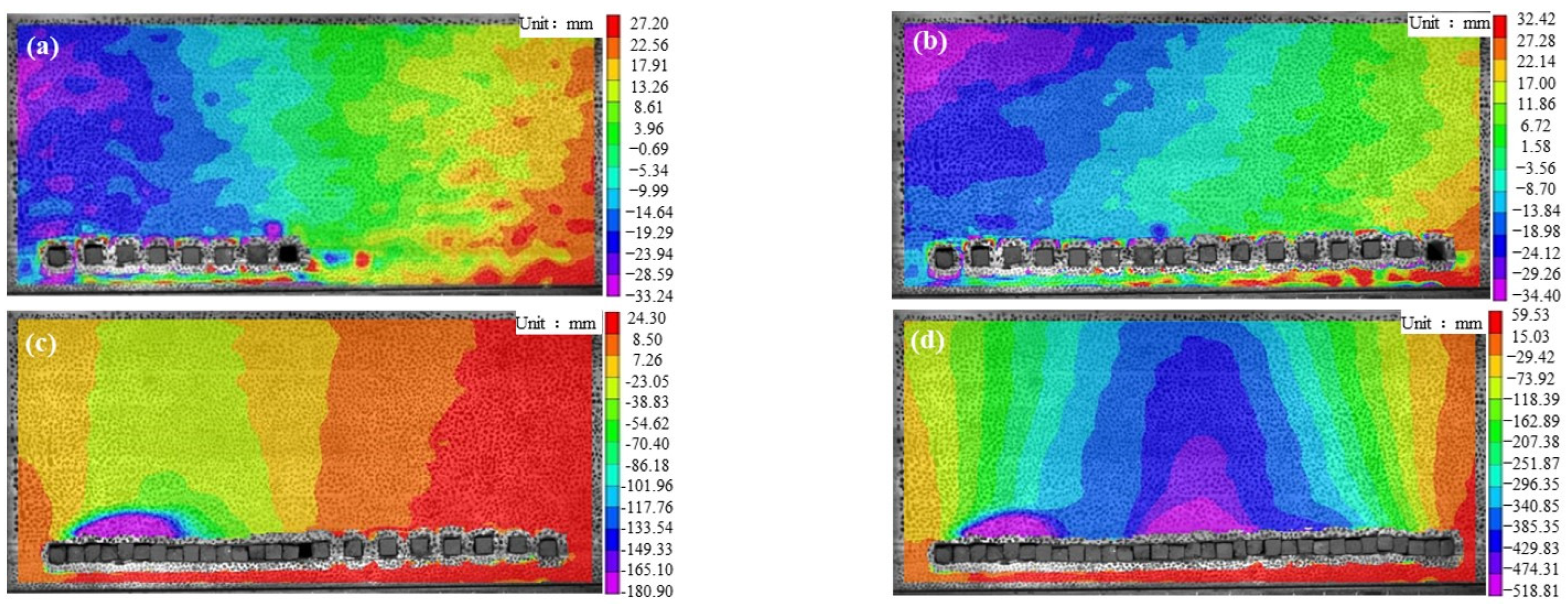
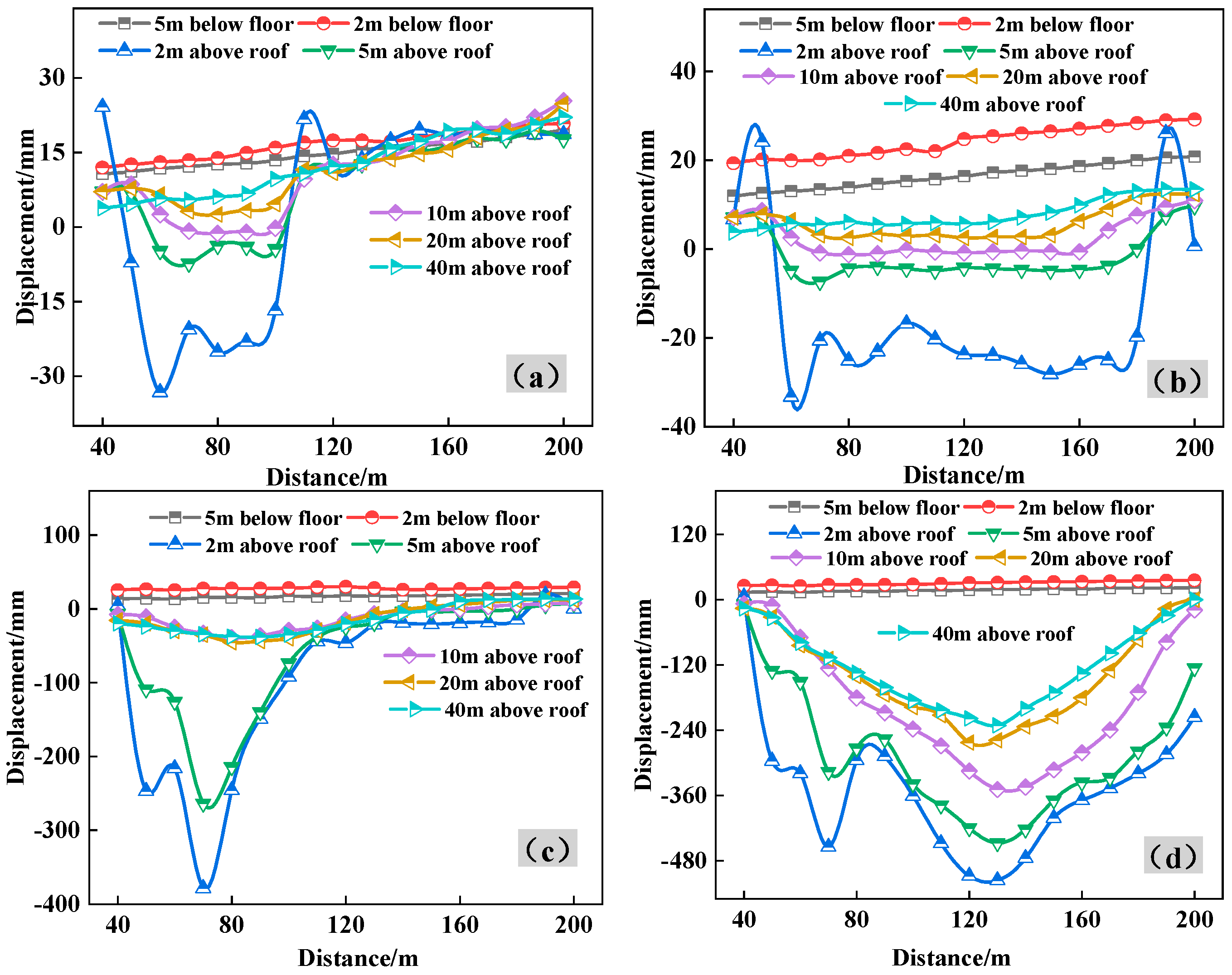
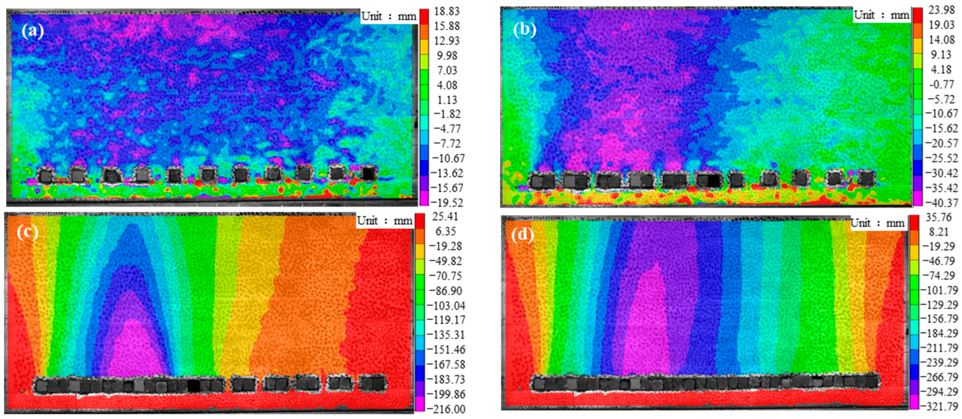
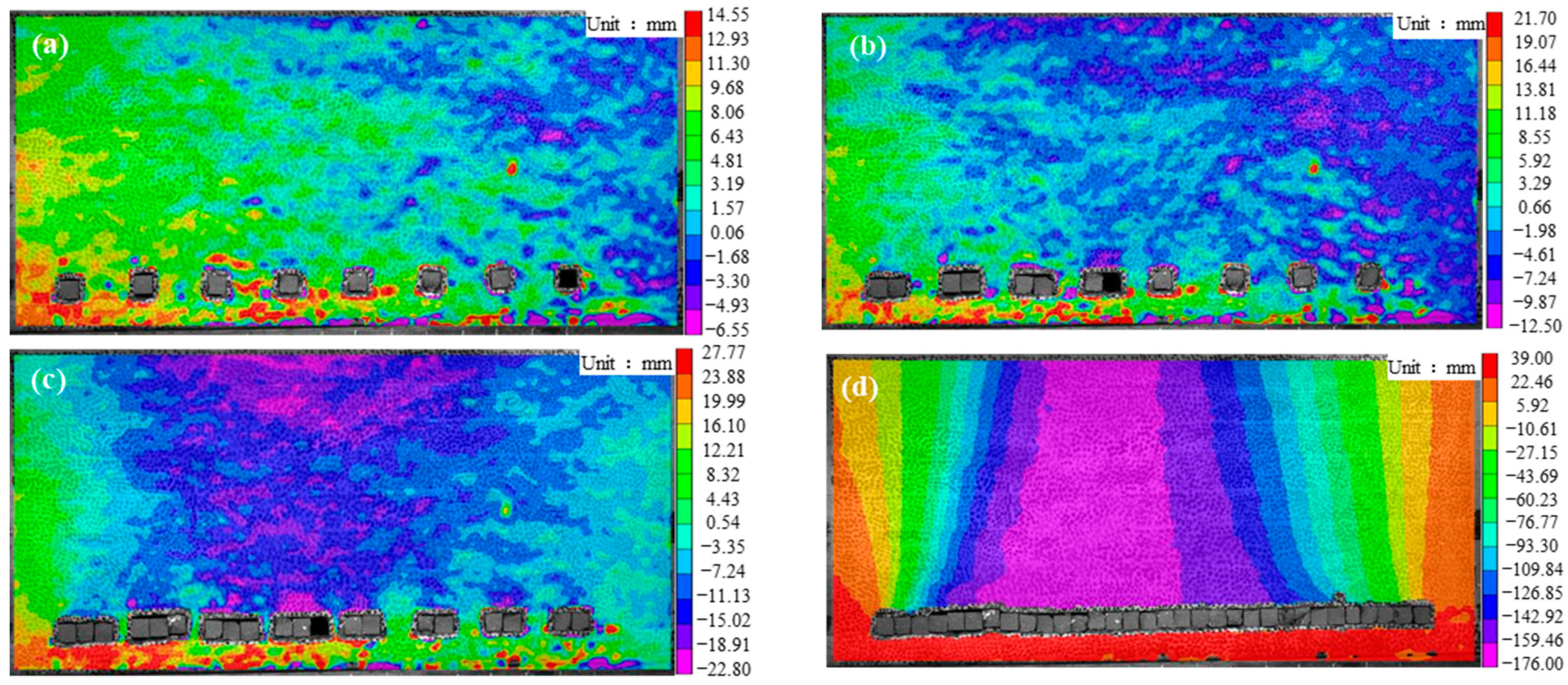
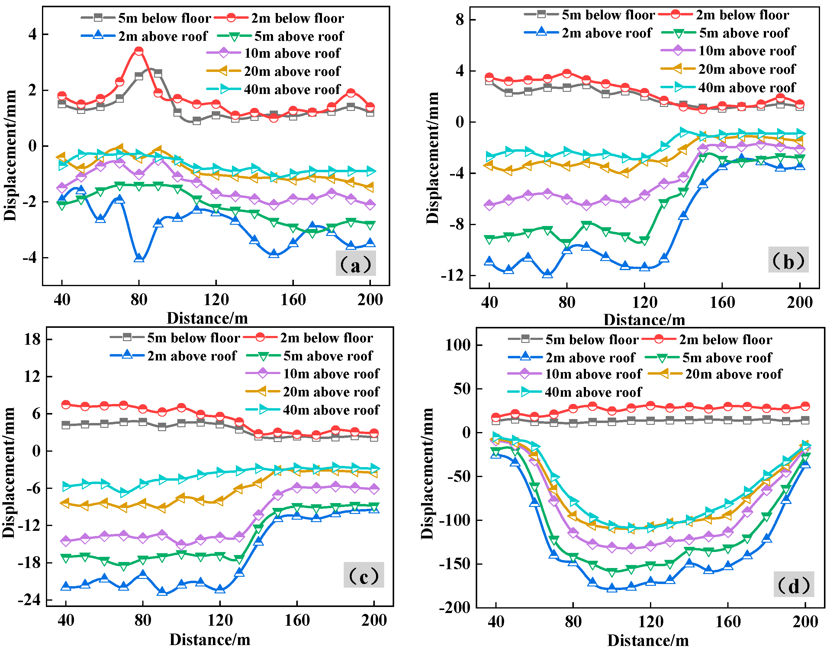
4.2. Characteristics of Fissure Development and Overburden Movement Law under Different Mining Sequences

Figure 9 shows the fracture development characteristics of the stope for different mining sequences. It can be seen from the figure that for different mining sequences, the roof does not have periodic fracture and collapse and only experiences small bending deformation. In the early stage of mining, either the coal pillar acts as the main load-bearing structure or the coal pillar-filling body acts as the joint load-bearing structure. There are no evident longitudinal fractures or separations on the roof, and there is very little displacement. The pressure coming from the stope is also not particularly noticeable. In the later stage of mining, the filling body completely replaces the coal pillar as the main load-bearing body. Since the filling rate cannot reach 100% and the strength and elastic modulus of the filling body are significantly lower than those of the coal pillar, the deformation of the filling body caused by the pressure results in the partial separation of the roof and longitudinal fissures. Thus, the roof undergoes a longitudinal fissure. In the last stage of mining, the filling body completely replaces the coal pillar as the main load-bearing body.
When the working face is completely excavated, the separation height for the mining sequences of “two-stage”, “three-stage”, and “four-stage” mining is 31 m, 21 m, and 14 m, respectively. The separation height increases with the increase in the number of mining phases, and the separation expands and then closes with the advancement of the working face. Due to the generation of higher pressure in the late stage of the “three-stage” and “four-stage” mining, some of the filling bodies experience cracking and spalling.
Figure 10 and Figure 11 show the vertical displacement contour of the stope and the vertical displacement curves of different layers above the roof during the two stages of mining, respectively. It is evident that following the initial stage of mining, the stope’s rock structure is still intact. The maximum subsidence of the roof is 34.40 mm, and the maximum floor heave is 32.42 mm. At this stage, the coal pillar plays the main bearing role. The filling body and the coal pillar support each other, and the rock stress in the stope is transferred to the filling body during the second stage of mining. Since the strength and filling rate of the filling body are lower than those of the coal pillar, when the second stage advances for 30 m, the immediate roof undergoes the separation and the longitudinal through fissure formation. The separation develops upwards as the working face continues to advance. When the working face is fully excavated, the maximum subsidence of the top plate is 518.81 mm, while the maximum floor heave is 59.53 mm.
Figure 12 and Figure 13 show the vertical displacement contour and the vertical displacement curves of different layers above the roof during the three-stage mining sequence, respectively. It can be observed that after the completion of the first two stages of mining, the maximum subsidence of the roof is 57.35 mm, and the maximum floor heave is 24.47 mm. The roof undergoes no separation and longitudinal fissures except for the bending subsidence. The load bearing of the coal pillar is gradually transitioned into the joint bearing of the coal pillar and the filling body. The filling body bears the majority of the overlaying load during the third stage of mining, and a part of the filling body becomes unstable due to cracking caused by the lack of strength. Following the completion of mining in the working face, the maximum subsidence of the roof is 321.79 mm, and the maximum floor heave is 45.44 mm.
Figure 14 and Figure 15 show the vertical displacement contour of the stope and the vertical displacement curves of different layers above the roof during the four-stage mining sequence, respectively. It can be inferred that after the completion of the first three stages of mining, the maximum subsidences of the roof are 6.55 mm, 14.94 mm, and 24.82 mm. The width of the coal pillar gradually decreases during mining, and the overburden load gradually shifts from the coal pillar to the filling body. This provides sufficient time for the solidification and strength formation in the filling body in the early stage. Some parts of the filling body undergo spalling in the process. When the working face is fully excavated, the maximum roof subsidence is 176.00 mm, and the maximum floor heave is 39.00 mm.
In summary, at a depth of 320 m, the maximum roof subsidence in the “two-stage”, “three-stage”, and “four-stage” mining sequences is 518.81 mm, 321.79 mm, and 176.00 mm, respectively. The maximum roof subsidence of the “three-stage” and “four-stage” mining sequences is only 62.0% and 33.9% that of the “two-stage” mining. This implies that increasing the mining stages can significantly reduce the amount of roof subsidence. In the last stage of mining, the maximum displacement of the roof accounts for 97.4%, 84.1%, and 94.1% of the final displacement; thereby, it is important to consider the stability of the roof throughout this phase of mining. After the completion of mining, the displacement curve of the roof is concave and sinking. The maintenance and curing time of the filling body in the early stage increases with the increase in the number of mining stages. This increases the elasticity modulus of the filling body and, therefore, reduces the amount of compression. The vertical displacement of the strata above the mining area of 1 m and 5 m displays upward and downward fluctuations at stages of mining, while the strata of 10 m and above show a slow sinking state.

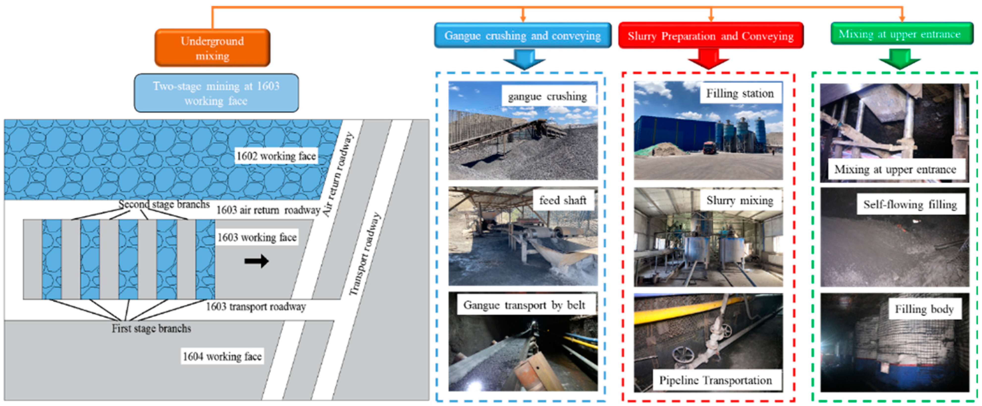
5. Engineering Application

5.1. Haoyuan Mine—Weak and Thick Coal Seam

The Haoyuan Mine, which mines No. 16 coal with an average depth of 320 m, average thickness of 6 m, and average dip angle of 8°, is located in Wuhai City, Inner Mongolia. It produces 600,000 tonnes of coal annually and has 1–5 layers of interbedded gangue with endogenous fissure development and poor integrity. The immediate roof of the coal seam is 3 m thick and interbedded with dense medium sandstone and mudstone, with thin layered thickness, developed laminations, and soft and weak interlayers. The main roof consists of 8 m thick medium sandstone. As the mining depth increases, it is affected by the Ordovician limestone water of the floor. As shown in Figure 16, the 1603 working face is designed with a “two-stage” mining sequence, with a strike length of 395 m, a face length of 50 m, and the width of the branch is 5 m. After mixing fly ash, cement, and water into a homogeneous slurry on the ground, the slurry is transported underground via the pipeline. After being crushed on the ground, the gangue is transmitted underground via a feeding well. From there, it is transported by belt to the upper branch entrance, where it is combined with the slurry to fill the mining area. The filling body is maintained for 28 days until the coal pillar is mined.
According to the real-time monitoring of the forces on the coal pillar and filling body by the YHY50W borehole stress meter “Huana Taian China“ during the mining, the average maximum vertical stresses in the coal pillar and filling body are 7.03 MPa and 3.89 MPa, respectively, which are basically the same as the results of numerical simulation. Furthermore, the coal pillar and filling body exhibit good stability. The internal structure of the roof is detected using the TS-C0601 borehole instrument “Changshen Wuhan China“, which consists of the host machine, depth encoder, wire disc, and φ40 probe, as shown in Figure 17. The roof of the branch has a small portion of delamination development in the range of 0–0.8 m, and the roof above 0.8 m is almost intact. The maximum subsidence of the roof after strengthening the support of the in situ along-airway is 165 mm, which is smaller than similar simulation results. This may be due to the good support effect on the branch during on-site excavation, which reduces the deformation of the overburden, and it is guaranteed to be used normally during the service period after the impact of two mining activities.

5.2. Chahasu Mine—Solid Waste Disposal

The Chahasu Mine, located in Ordos City, Inner Mongolia, produces 10 million tonnes of coal annually. The burial depth of 3–1 coal is 400 m, with an average thickness of 5 m and a dip angle ranging between 1°–3°. The immediate roof of the coal seam is a 2 m thick mudstone, while the main roof is a 10 m thick medium sandstone. The annual emission of gangue in this mine is more than 1 million tonnes. To dispose of the gangue, 301 and 302 working faces are established in the 31st mining area. The 301 and 302 working faces test the “four-phase” and “three-phase” mining sequences, respectively. The length of both working faces is 500 m, the face length is 50 m, and the width of the branch lane is 5 m. Since the coal seam is near horizontal, the slurry is mixed on the ground. After the gangue is crushed to a size of less than 20 mm by the gangue crushing system, it is mixed with fly ash, cement, and mine water according to the proportion of the grading and then conveyed via the pipeline to the transport lane. The branch is blocked from both sides after excavation, and the slurry is introduced into the roof of the branch through the three-way valves. The filling system of mine ground and underground is shown in Figure 18.
At present, 301 and 302 working faces have been mined, with a total production of 350,000 tonnes of coal, 245,000 tonnes of gangue, 87,500 tonnes of fly ash, and 100,000 tonnes of mine water disposed. As shown in Figure 19, the maximum stresses in the coal pillar and filling body of 301 working faces are 16.50 MPa and 7.56 MPa, respectively. The maximum stress concentration coefficient of the coal pillar is 1.65, and the maximum stresses in the coal pillar and filling body of 302 working faces are 14.32 MPa and 5.87 MPa, respectively. The maximum stress concentration coefficient of the coal pillar is 1.43, and the maximum stress concentration coefficient of the filling body is 1.43. The stress of the coal pillar and filling body in the four-stage mining is lower than that in the three-stage mining, which is similar to the numerical simulation results. The filling body is tightly connected to the roof. The maximum subsidence of the roof is 102 mm on average, and the overall mining pressure appears to be more moderate, which achieves significant economic and social benefits.

6. Conclusions

The present study employs numerical simulation and similarity simulation methods to study the influence of branch mining sequences on the stope pressure phenomenon. The following conclusions were obtained from the results:
(1) According to numerical simulation results, leaving a broad coal pillar in the early stage of mining offers better stability than two-stage, three-stage, and four-stage mining and provides adequate time for the filling body to solidify. However, in the late stage of mining, coal pillar stress is significantly higher than that in the two-stage mining. When the width of the coal pillar is 10 m, its stress concentration coefficient is the highest. It is necessary to strengthen the control of the coal ribs in the deeply buried or soft coal seams to prevent their instability and destruction;
(2) Similarity simulation results show that the integrity of the overburden is good during different mining sequences, with only limited delamination and longitudinal fissures. The displacement curve of the roof shows concave subsidence, with the maximum subsidence for the two, three, and four stages as 518.81 mm, 321.79 mm, and 176.00 mm. The heights of delamination development are 31 m, 21 m, and 14 m, respectively. The maximum roof subsidence in the three- and four-stage mining sequences is only 62.0% and 33.9% of that in the two-stage mining, which is significantly reduced by increasing the number of stages;
(3) The application of CMCB was carried out in response to the demands of weak coal seam mining in Haoyuan Mine and solid waste disposal in Chahasu Mine. The “two-stage”, “three-stage”, and “four-stage” mining sequences were practised according to the actual conditions on-site. According to the actual conditions of the site, good engineering application results have been achieved, which is conducive to achieving safe, green, and efficient mining of coal resources.

Author Contributions

All authors contributed to this study’s conception and design. Material preparation, data collection, and analysis were performed by H.L., Y.Y. and C.C. The first draft of the manuscript was written by H.L. The corresponding author is C.D. All authors commented on previous versions of this manuscript. All authors have read and agreed to the published version of the manuscript.

Funding

This research is supported by the National Natural Science Foundation of China (Grant no. (52204085).

Data Availability Statement

The data used to support the findings of this study are available from the corresponding author upon request.

Conflicts of Interest

The authors declare no conflicts of interest.

References

  1. Yuan, L.; Zhang, P. Development status and prospect of geological guarantee technology for precise coal mining. J. China Coal Soc. 2019, 44, 2277–2284. [Google Scholar]
  2. Qian, M.; Xu, J.; Wang, J. Further on the sustainable mining of coal. J. China Coal Soc. 2018, 43, 1–13. [Google Scholar]
  3. Li, Q.; Li, X.; Xu, J.; Xu, Z.; Zhang, C. Research advances in mining fractures evolution law of rock strata and ecological treatment technology. Coal Sci. Technol. 2022, 50, 28–47. [Google Scholar] [CrossRef]
  4. Xie, H.; Ren, S.; Xie, Y.; Jiao, X. Development opportunities of the coal industry towards the goal of carbon neutrality. J. China Coal Soc. 2021, 46, 2197–2211. [Google Scholar]
  5. Liu, F.; Cao, W.; Zhang, J.; Cao, G.; Guo, L. Current technological innovation and development direction of the 14th Five-Year Plan period in China coal industry. J. China Coal Soc. 2021, 46, 1–15. [Google Scholar]
  6. Peng, S.; Bi, Y. Strategic consideration and core technology about environmental ecological restoration in coal mine areas in the Yellow River basin of China. J. China Coal Soc. 2020, 45, 1211–1221. [Google Scholar]
  7. Lin, H.; Yang, R.; Li, Y.; Lu, B.; Xu, B.; Fan, Z.; Li, J. Application of short-wall continuous mining and continuous backfilling cemented-fill mining technology. Chin. J. Eng. 2022, 44, 981–992. [Google Scholar]
  8. Xu, B.; Li, Y.; Lu, B.; Li, J. Three measurement relationship and control principle of overburden movement in cemented filling. J. China Coal Soc. 2022, 47, 1055–1071. [Google Scholar]
  9. Shao, X.; Tao, Y.; Liu, E.; Zhao, B.; Li, X.; Wang, L.; Li, L.; Tang, R.; Zhang, J. Study and application of paste-like filling mining parameters of shallow buried coal seam in Northern Shaanxi. Coal Sci. Technol. 2021, 49, 63–70. [Google Scholar]
  10. Wang, S.; Li, Y.; Li, Q.; Wang, Z.; Wang, Y. Influence of gangue gradation coefficient on the performance of filling material based on talbol theory. J. Min. Saf. Eng. 2022, 39, 683–692. [Google Scholar]
  11. Yang, B.; Han, Y.; Yang, P.; Li, Y. Research on Ratio of High Concentration Cementation Stowing Materials in Coal Mine. Coal Sci. Technol. 2014, 42, 30–33. [Google Scholar]
  12. Sun, Q.; Tian, S.; Sun, Q.; Li, B.; Cai, C.; Xia, Y.; Wei, X.; Mu, Q. Preparation and microstructure of fly ash geopolymer paste backfill material. J. Clean. Prod. 2019, 2, 376–390. [Google Scholar] [CrossRef]
  13. Huang, Y.; Duan, X.; Wang, Y.; Luo, H.; Hao, X. Research on non-full pipeline flow transportation and prevention method of coal gangue cemented backfill. Coal Sci. Technol. 2020, 48, 117–122. [Google Scholar]
  14. Li, B.; Zhang, J.; Yan, H.; Zhou, N.; Li, M. Experimental investigation into the thermal conductivity of gangue-cemented paste backfill in mine application. J. Mater. Res. Technol. 2022, 16, 1792–1802. [Google Scholar] [CrossRef]
  15. Ma, L.; Zhang, D.; Jin, Z.; Wang, S.; Yu, Y. Theories and methods of efficiency water conservation mining in short-distance coal seams. J. China Coal Soc. 2019, 44, 727–738. [Google Scholar]
  16. Lin, H.; Yang, R.; Lu, B.; Li, Y.; Fang, S.; Fan, Z.; Li, Z. Overlying strata movement law of continuous mining and continuous backfilling cemented-fill mining. Environ. Earth Sci. 2021, 80, 688. [Google Scholar] [CrossRef]
  17. Zhao, Y.; Ran, H.; Feng, G.; Guo, Y.; Fan, Y. Damage evolution and failure characteristics of cemented gangue backfill body with different height-width ratios under uniaxial compression. J. Min. Saf. Eng. 2022, 39, 674–682. [Google Scholar]
  18. Wu, J.; Jing, H.; Pu, H.; Zhang, X.; Meng, Q.; Yin, Q. Macroscopic and mesoscopic mechanical properties of cemented waste rock backfill using fractal gangue. Chin. J. Rock Mech. Eng. 2021, 40, 2083–2100. [Google Scholar]
  19. Wang, F.; Li, G.; Ban, J.; Peng, X.; Li, S.; Liu, S. Synergistic bearing effect of backfilling body and coal pillar in deep mining. J. Min. Saf. Eng. 2020, 37, 311–318. [Google Scholar]
  20. Zhang, Y.; Cao, S.; Guo, S.; Wan, T.; Wang, J. Study on the height of fractured water-conducting zone under aquifer for short wall blocking mining. J. Min. Saf. Eng. 2018, 35, 106–111. [Google Scholar]
  21. Cao, Z.; Xu, P.; Li, Z.; Zhang, M.; Zhao, Y.; Shen, W. Joint Bearing Mechanism of Coal Pillar and Backfilling Body in Roadway Backfilling Mining Technology. CMC—Comput. Mater. Contin. 2018, 54, 137–159. [Google Scholar]
  22. Deng, X.; Zhang, J.; Klein, B.; de Wit, B.; Zhang, J. Time-dependent lateral pressure of the filling barricade for roadway cemented backfill mining technology. Mech. Time-Depend. Mater. 2020, 24, 41–58. [Google Scholar] [CrossRef]
  23. Liang, X.; Ding, C.; Zhu, X.; Zhou, J.; Chen, C.; Guo, X. Visualization study on stress evolution and crack propagation of jointed rock mass under blasting load. Eng. Fract. Mech. 2024, 296, 109833. [Google Scholar] [CrossRef]
  24. Ye, Y.; Shi, Y.; Wang, Q.; Wang, Q.; Liu, Y.; Yao, N.; Lu, F. Experimental study of deformation of wall rock and stoping sequence in mining gently inclined and multilayer deposits by backfill mining. J. Min. Saf. Eng. 2015, 32, 407–413. [Google Scholar]
  25. Li, J.; Zhang, J.; Hou, J.; Wang, L.; Yin, Z.; Li, C. Multiple disturbance instability mechanism of dynamic pressure roadway and mining sequence optimization. J. Min. Saf. Eng. 2015, 32, 439–445. [Google Scholar]
  26. Wang, Y.; Cao, A.; Dou, L.; Guo, X.; Du, B.; Liu, H.; Zhu, L. Study on the Rock Burst Risk Caused by the Irrational Layout of the Mining Exploitation. J. Min. Saf. Eng. 2012, 29, 827–832. [Google Scholar]
  27. Hu, J.; Xi, Z.; Luo, X.; Zhou, K.; Ai, Z. Optimization of mining sequence based on rock mass time-varying mechanics parameters. J. Cent. South Univ. 2017, 48, 2759–2764. [Google Scholar]
  28. Lu, B.; Zhang, X.; Li, F.; Zhang, B.; Pang, Z. Study and application of short-wall gangue cemented backfilling technology. J. China Coal Soc. 2017, 42, 7–15. [Google Scholar]
  29. Tu, S.; Hao, D.; Li, W.; Liu, X.; Miao, K.; Yang, Z. Construction of the theory and technology system of selective mining in “mining, dressing, backfilling and X” integrated mine. J. Min. Saf. Eng. 2020, 37, 81–92. [Google Scholar]
  30. Liu, J.; Li, X.; He, T. Application status and prospect of backfill mining in Chinese coal mines. J. China Coal Soc. 2020, 45, 141–150. [Google Scholar]
  31. Guo, G.; Guo, K.; Zhang, G.; Li, H.; Hu, S. Research on deformation characteristics of coupled coal-backfills bearing in deep strip backfilling mining. J. Min. Saf. Eng. 2020, 37, 101–109. [Google Scholar]
  32. Lin, H.; Yang, R.; Li, Y.; Fang, S. Deformation Mechanism and Control Technology of Coal Roadway with Thin Sand-mudstone Interbed Roof. Min. Metall. Explor. 2022, 40, 421–433. [Google Scholar] [CrossRef]
  33. Zhou, N.; Xu, J.; Zhang, J.; Ma, D.; Li, Z.; Yao, Y. Study on the weaking mechanism of hard overburden rock burst disaster by backfilling. Chin. J. Rock Mech. Eng. 2023, 42, 2412–2426. [Google Scholar]
  34. Yu, L.; Luo, J.; Jia, C.; Yao, D.; Luo, J. Research on Application of Digital Image Correlation Method in Mechanical Property Test. Nucl. Power Eng. 2022, 43, 146–151. [Google Scholar]
Figure 1. Mining sequence of CMCB.
Processes 12 00442 g001
Figure 2. Deformation of coal pillar and filling body.
Processes 12 00442 g002
Figure 3. Numerical model of CMCB mine.
Processes 12 00442 g003
Figure 4. Three-dimensional mining stress field distribution of coal pillar-filling body under two-stage mining sequence.
Processes 12 00442 g004
Figure 5. Three-dimensional mining stress field distribution in the coal pillar-filling body under three-stage mining sequence.
Processes 12 00442 g005
Figure 6. Three-dimensional mining stress field distribution of coal pillar-filling body under four-stage mining sequence.
Processes 12 00442 g006
Figure 7. Maximum vertical stress at each position under different mining sequences: (a) two-stages; (b) three-stages; (c) four-stages.
Processes 12 00442 g007
Figure 8. Digital image correlation method used as measuring system.
Processes 12 00442 g008
Figure 9. Fracture development characteristics of CMCB stope under different mining sequences.
Processes 12 00442 g009
Figure 10. Vertical displacement contour of overburden under two-stage mining sequence: (a) 50 m advance in the first stage; (b) 100 m advance in the first stage; (c) 50 m advance in the second stage; and (d) 100 m advance in the second stage.
Processes 12 00442 g010
Figure 11. Displacement curve of strata above the roof of two-stage mining: (a) advance 50 m in the first stage; (b) advance 100 m in the first stage; (c) advance 50 m in the second stage; and (d) advance 100 m in the second stage.
Processes 12 00442 g011
Figure 12. Vertical displacement contour of overburden under three-stage mining sequence: (a) 50 m advance in the first stage; (b) 100 m advance in the first stage; (c) 50 m advance in the second stage; and (d) 100 m advance in the second stage.
Processes 12 00442 g012
Figure 13. Displacement curve of strata above the roof of three-stage mining (a) advance 50 m in the first stage, (b) advance 100 m in the first stage, (c) advance 50 m in the second stage, and (d) advance 100 m in the second stage.
Processes 12 00442 g013
Figure 14. Vertical displacement contour of overburden under four-stage mining sequence: (a) 50 m advance in the first stage; (b) 100 m advance in the first stage; (c) 50 m advance in the second stage; and (d) 100 m advance in the second stage.
Processes 12 00442 g014
Figure 15. Displacement curve of strata above the roof of four-stage mining: (a) advance 50 m in the first stage; (b) advance 100 m in the first stage; (c) advance 50 m in the second stage; and (d) advance 100 m in the second stage.
Processes 12 00442 g015
Figure 16. Underground mixing mode of filling slurry.
Processes 12 00442 g016
Figure 17. On-site monitoring: (a) Stress of coal pillar and filling body; (b) YHY50W borehole stressmeter and TS-C0601 borehole instrument; (c) Borehole scoping results of gob-side entry retaining.
Processes 12 00442 g017
Figure 18. Surface and underground backfilling system.
Processes 12 00442 g018
Figure 19. On-site monitoring: (a) Stress of coal pillar and filling body; (b) Roof subsidence of gob-side entry retaining.
Processes 12 00442 g019
Table 1. Basic information of CMCB mine.
NameProduction Capacities (MTA)Extraction StageWidth of Branch (m)NameProduction Capacities (MTA)Extraction StageWidth of Branch (m)
Yuxing mine0.6two5Xinjulong mine7.5two4.5
Haoyuan mine0.6two5Yiqiao mine0.8two4.5
Huangbaici mine1.2two5Xincun mine0.9four5
Limin mine1.8three5Wangtaipu mine2.6four6
Wuhushan mine2.0two5Qianwan mine0.9two5
Changcheng fifth mine1.8two4Xinjian mine1.2two4
Changcheng sixth mine (plan)1.5Zishen mine0.9two5
Tianyu mine0.6two5Xinzhi mine0.28two5
Gonggeyingzi mine0.3three4Changcun mine8.0four5
Gongwusu mine (plan)2.7Dianpin mine2.6two6
Chahasu mine10.0three/four5Sihe mine1.8two6
Dingjiaqu (plan)2.3Sima mine3.0two5
Huhewusu mine1.2three5Dongshan mine1.5four5
Guanbanwusu mine (plan)2.4Yachen mine (plan)0.6
Suncun mine0.6two5Sucun mine (plan)0.9
Gaozhuang mine (plan)3.6Changxing mine0.9two6
Zhaizheng mine2.0two4.5Yuyang mine3.0two5.4
Xiezhuang mine2.0two5Guojiawan mine (plan)2.1
Table 2. Physical and mechanical parameters of surrounding rock.
LithologyDensity/kg/m3Bulk Modulus/GPaShear Modulus/GPaCohesion/MPaAngle of Internal/°Tensile Strength/MPa
Sandy mudstone25503.62.12.52292.5
Mudstone22005.44.82.6242.2
Coal14001.270.431.9251.2
Fine sandstone2600107.56.5323.2
Medium sandstone24805.954.13272.7
Filling body18500.960.40.75160.5
Table 3. Proportion of materials [33].
No.LithologyThickness (m)RatioMaterial Consumption (kg)
Medium SandLimeGypsumWater
12Sandy mudstone20864122.409.186.1215.30
11Fine sandstone17846106.085.307.6913.26
10Medium sandstone20855119.047.447.44148.8
9Coal1097334.022.631.134.20
8Mudstone1086452.803.962.646.60
7Sandy mudstone686436.722.751.844.59
6Fine sandstone884642.432.123.085.30
5Interbed Sandy mudstone 386418.361.370.922.30
4Coal697320.411.580.682.52
3Mudstone986447.523.322.385.94
2Fine sandstone1184658.342.924.237.29
1Filling body684626.642.001.333.33
Disclaimer/Publisher’s Note: The statements, opinions and data contained in all publications are solely those of the individual author(s) and contributor(s) and not of MDPI and/or the editor(s). MDPI and/or the editor(s) disclaim responsibility for any injury to people or property resulting from any ideas, methods, instructions or products referred to in the content.

