Article

Numerical Study on the Fracturing of Deep Rock Masses by Blasting Based on the Material Point Method

1
State Key Laboratory of Intelligent Construction and Healthy Operation and Maintenance of Deep Underground Engineering, College of Architecture and Environment, Sichuan University, Chengdu 610065, China
2
National Key Laboratory of Fundamental Algorithms and Models for Engineering Simulation, Chengdu 620107, China
3
State Key Laboratory of Precision Blasting, Jianghan University, Wuhan 430056, China
4
Hubei Key Laboratory of Blasting Engineering, Jianghan University, Wuhan 430056, China
*
Author to whom correspondence should be addressed.
Processes 2024, 12(6), 1048; https://doi.org/10.3390/pr12061048
Submission received: 11 April 2024 / Revised: 13 May 2024 / Accepted: 18 May 2024 / Published: 21 May 2024

Abstract

:
Blasting is a prevalent technique in deep rock excavation, with the state of rock fragmentation under high in-situ stress conditions being distinct from that under low in-situ stress conditions. A new material point method framework utilizing the generalized interpolated material point and convective particle domain interpolation functions was implemented to simulate the single-hole blasting process, analyze the stress distribution around the blasting hole, and elucidate the mechanism of how ground stress influences the expansion of blasting cracks through the interaction with the blasting load. In addition, the dynamic relaxation method realizes the stress’s initialization. It was concluded that the in-situ stress can increase the compressive stress induced by blasting load, whereas it decreases the caused tensile stress. With the increase in the ground stress, the scale of the cracks decreases. Under the non-isobaric condition, the blast-induced cracks preferentially expand along the high stress with the increase in the stress difference between the horizontal direction and the vertical direction, and the blast-induced cracks are suppressed to the greatest extent in the direction of the minimum ground stress.

1. Introduction

The ongoing advancement of the global economy has precipitated a burgeoning demand for natural resources. Deep resource extraction has become ubiquitous as shallower mineral deposits are gradually depleted [1,2]. Numerous mines worldwide operate at depths exceeding 1000 m below the surface, with examples in Canada and the United States reaching depths surpassing 2000 m [3]. Noteworthy among these is the West Wits mine in South Africa, distinguished as a pioneer in deep shaft mining, housing three gold mines—TauTona, Savuka, and Mponeng—all surpassing a depth of 3700 m. The mechanical behavior of rock masses is intricate, contingent upon factors such as mineral characteristics, degree of jointing, in-situ stress, and rock weathering [4,5,6,7,8,9]. Challenges associated with high temperature, in-situ stress, and permeability are notably pronounced in deep-rock engineering, with in-situ stress playing a pivotal role irrespective of geological conditions [10,11]. For instance, in the TauTona gold mine, in-situ stress approaches 100 MPa at 3500 m [12].
Drilling and blasting methods, including rock excavation through drilling, charging, and blasting, have long served as the primary approach for rock excavation in underground construction, as shown in Figure 1, offering adaptability to varied geological conditions, cost-effectiveness, and particular suitability for complex rock construction [9,13,14,15]. While surface and shallow rock masses typically experience low in-situ stresses with minimal impact on rock fragmentation, deep mines encounter in-situ stresses nearing or surpassing the rock’s uniaxial compressive strength. Moreover, rock properties at considerable depths differ from those at shallower levels. With the advent of deep mining, extensive zonal disintegration of deep-rock masses occurs, transitioning the damage pattern of rocks from brittle to ductile, resulting in a sharp rise in rock burst accidents and induced phenomena, like seismic activity [16], Nevertheless, there remains a dearth of comprehensive research examining the effects of static in-situ stresses and dynamic blast loads on the blasting behavior of deep-rock masses. Lu et al. [17] emphasized that traditional pre-cracking and blasting methods become inapplicable when static in-situ stress surpasses 10–12 MPa. Therefore, a thorough understanding of the blasting mechanisms in rock masses subjected to high in-situ stress is paramount.
Over the past few decades, extensive research has delved into the blasting mechanism of rock formations, employing various methodologies, such as theoretical analysis, field blasting tests, and numerical simulations. The foundational blasting theories were predominantly established by Kutter and Fairhurst [18]. In-situ stress significantly influences the propagation of blast-induced cracks, a focal point of numerous studies investigating crack initiation and extension under in-situ stress conditions. Field tests conducted by Nicholls et al. [19] revealed that pre-splitting along the direction of maximum in-situ compressive stress is notably more accessible than in other directions. Some cracks initially initiated radially but subsequently deviated towards the direction of the applied static stress field. Some blast tests on diverse materials under initial rock pressure were conducted by Jung et al. [20], illustrating that crack propagation aligned with the applied pressure. Yang et al. [21] investigated blast-induced crack behavior in dynamic and static stress fields through focal dispersion experiments, revealing that perpendicular pre-compressive stress to the crack extension direction reduces stress concentration at the crack tip and impedes crack extension. In contrast, parallel pre-compressive stress exerts no effect on extension.
However, due to challenges associated with field blasting tests, such as high costs and difficulty in observing blast-induced cracks, experimental studies have yet to extensively explore the effects of in-situ stress on the blasting behavior of deep-rock masses. With advancements in computational power, numerical simulation methods have become valuable research tools for investigating blast damage or rock fracture [22]. Two primary numerical methods are commonly applied: mesh [23,24] and meshless [25,26]. Bendezu et al. [27] introduced a numerical analysis method based on the finite element method to simulate blast-induced challenges to rock-fracture extension. While the finite element method (FEM) is continuum-based, making it difficult to simulate crack extension and rock fragmentation directly, meshless methods and hybrid mesh-meshless methods have gained popularity for rock-blasting simulation in recent years. Fakhimi and Lanari [28] utilized a combination of the Discrete Element Method (DEM) and Smooth Particle Hydrodynamics (SPHs) to simulate rock blasting, with the behavior of the rock simulated using cohesive DEM and the explosive’s explosion simulated by SPH. However, the SPH method suffers from tensile instability, leading to numerical breaks, shape function inconsistency, and difficulty introducing intrinsic boundary conditions [29]. The material point method employs a dual Lagrangian and Eulerian description, capitalizing on the strengths of both methodologies, proving effective in solving fracture and significant deformation problems. The standard material point method, known as sMPM and developed by Sulsky [30,31], faces issues, like severe mesh traversal and tensile instability. Bardenhagen and Kober [32] addressed mesh traversal by introducing particle eigenfunctions and proposed the generalized interpolated material point method (GIMP-MPM). However, GIMP-MPM does not handle tensile instability well. Sadeghirad et al. [33,34] developed a series of convective particle domain interpolation (CPDI-MPM) techniques to alleviate tensile instability. CPDI-MPM treats material points as particle domains, accurately tracking tensile, shear, and rotational deformations by monitoring the motion of domain angles of mass points, surpassing previous material point methods in accuracy. While various enhanced extensions of material point methods have emerged, GIMP and CPDI methods are the prominently utilized approaches. Wan et al. [35] employed a combination of the generalized interpolated material point method (CPDI) and the para-basin interpolation technique (CPDI) to simulate the rock-blast fracture process under three-dimensional conditions comprehensively.
The above studies have yielded valuable insights into the influence of in-situ stress on blast-induced cracks. Previous numerical investigations into the effect of initial stress on blast fragments typically represented blast load through a pressure–time history curve. However, controversies persist regarding the selection of peak pressure, load function, and blast load duration, which fail to characterize explosive blasts accurately. The material model significantly affects the numerical simulation outcomes [36]. and the JH-2 model is a mature model suitable for rock blasting in in-situ stress conditions [37]. Here, a novel coupled static and dynamic load model is introduced, utilizing the material point method to simulate explosives, rock, and air, exploring the impact of in-situ stress on the evolution of rock single-hole blasting damage and analyzing the processes of crack initiation and extension.

2. Material Point Method

2.1. Governing Equations

An updated Lagrangian description is usually used in numerical methods to solve problems characterized by high strain rates and large deformation, especially in scenarios involving blasting and high-velocity impacts, and the corresponding governing equations are Equations (1)–(3).
d ρ d t + ρ v k x k = 0
σ i j x j + ρ b i = ρ u ¨ i
ρ e ˙ = ε ˙ i j σ i j
where ρ , v k , σ i j , b i , u ¨ i , e ˙ , and ε ˙ i j are density, velocity vector, component of the Cauchy stress tensor, body force per unit mass, displacement vector, energy rate, and component of the strain rate tensor, respectively.
Like most numerical methods, the weak form of the governing equations in the material domain Ω can be written as the following equation:
Ω     ρ u ¨ i δ u i d Ω + Ω     σ i j δ u i , j d Ω Ω     ρ b i δ u i d Ω = 0

2.2. MPM Solution Scheme

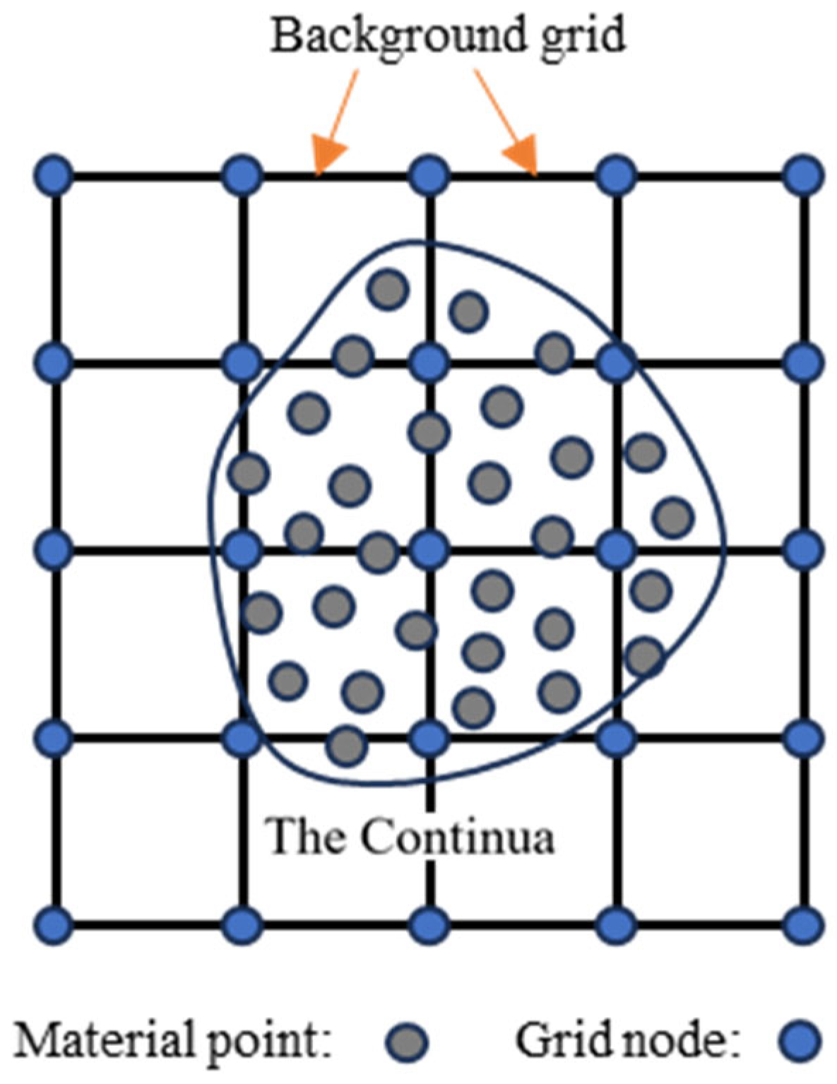
The MPM discretizes the continua into a cluster of particles with the lumped mass, as shown in Figure 2. Material points carry all physical attributes of the continuum and move within the background grid. The base function transfers physical information, such as velocities and stresses, between a cluster of material points and a background grid, eliminating the necessity to deal with convective terms. The momentum conservation equations are solved on a regular Eulerian background mesh, avoiding the problem of mesh distortion. Then, the discretized form of Equation (4) can be written as Equation (5).
p = 1 n p m p u ¨ i p δ u i p + p = 1 n p V p σ i j p δ u i p , j p = 1 n p m p b i p δ u i p = 0
where n p   is the total number of the particles,   m p , V p , u i p , δ u i p , and b i p are the mass, volume, displacement, virtual displacement, and body force of the particle p , respectively.
In the material point method, the weak form of the momentum conservation equation is solved on the background grid, and the background grid node data can be obtained by interpolating the material points data. Due to the arbitrariness of the virtual displacement δ u i , the momentum equation on the background grid can be written as the following equation:
  P ˙ i I = f i I i n t + f i I e x t ,   x I Γ u
where Γ u is the displacement boundary,
P i I = m I u ˙ i I
P i I is the grid nodal momentum,
m I = p = 1 n p N I p m p
m I is the lumped grid nodal mass,
f i I i n t = p = 1 n p V p N I p , j σ i j p
f i I e x t = p = 1 n p m p N I p b i p
where f i I i n t , f i I e x t are the internal nodal force and the external nodal force, respectively.

2.3. Base Function of GIMP and CPDI

The data of the background grid nodes are calculated by interpolating the data of the material points. Hence, the base functions are crucial for the accuracy of the numerical simulation results. However, the derivative of the   C 0 standard linear interpolation function is discontinuous between grids, leading to perturbations when material points instantaneously cross grid boundaries. This can cause short-term sudden changes in stress and energy, compromising accuracy and potentially distorting results. In the damage model, the beginning of damage is usually related to the stress, so grid crossing must be avoided. In addition, the numerical fracture will happen when particle sets are subjected to solid stretching.
Numerical fracture and grid crossing perturbations will result in the instability of the numerical simulation. Fine meshing enhances the accuracy of numerical simulation, but this is also more likely to produce grid-crossing instabilities. A straightforward approach to mitigate this is increasing material points and reducing time steps, although this method could be more efficient. A better way to reduce this error is to use B-spline shape functions, such as the generalized interpolating function (GIMP) [32], where both the function and its derivatives are C 1 continuous. Sadeghirad et al. [33,34] proposed a Convected Particle Domain Interpolation (CPDI) technique in which the convection of a continuum set of material points is more accurate than the generalized material point interpolation function. This feature is crucial for eliminating the instability in the stretching process, and CPDI has a C 1 continuous base function, like GIMP.

2.4. Time Step Control

The numerical stability of an explicit dynamics program depends on the time increment at each step. In the material point method, the time integration occurs on a spatially fixed background grid. In determining the critical time step, unlike the technique using Lagrangian grids, the material point method needs to consider the velocity of the material in addition to the material speed of sound. This consideration is particularly crucial for scenarios involving ultrahigh-speed impacts and explosions, where the velocity of the material point approaches the material speed of sound. According to the Courant–Friedrichs–Lewy stability condition, the propagating distance of the physical information is less than the element size during one timestep [38]. Therefore, a recommended time step is given by Equation (11).
t c r = h g m a x c p + u p
where t c r is the critical time increment,   h g is the length of the background grid,   c p is the wave speed, and u p is the particle’s velocity. The time step in the calculation process can be adjusted by the factor α   (0 < α < 1 ).

3. Theoretical Analysis and Numerical Model

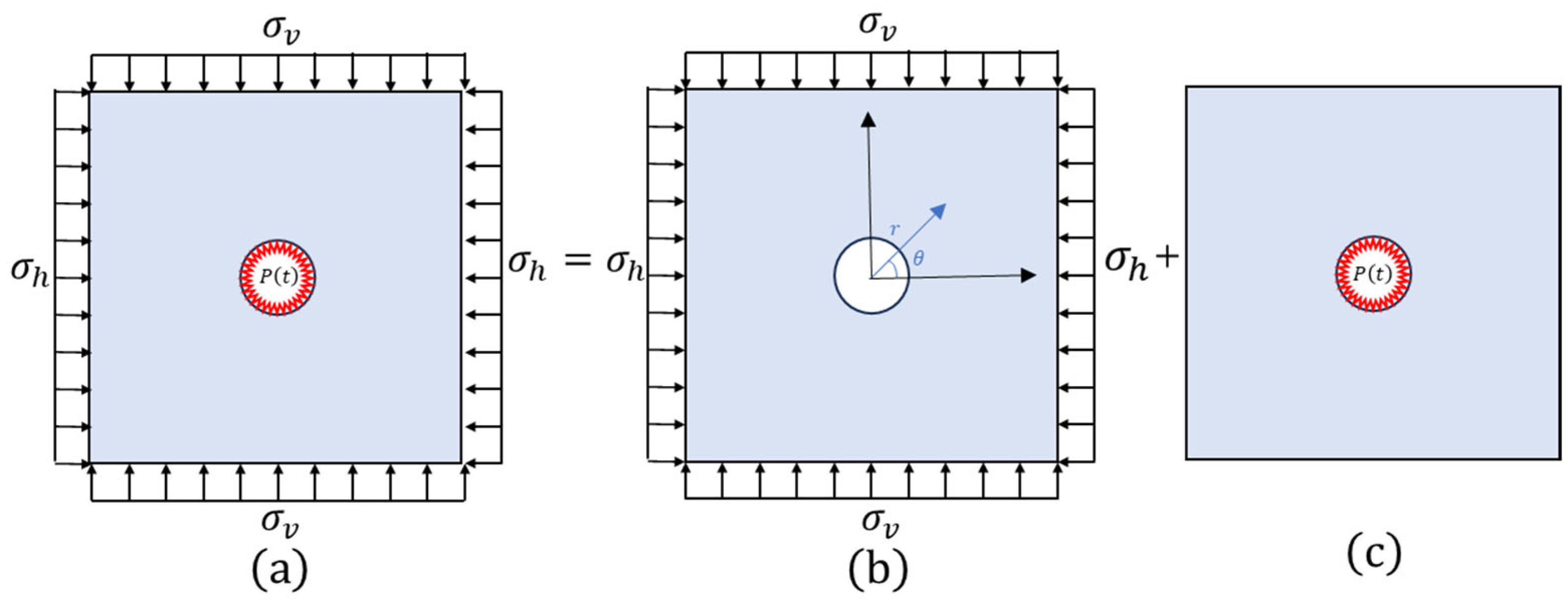
In the tunnel blasting excavation process, the axial size of the tunnel is much larger than the cross-section size. It is often used in a continuous column charging mode along the axial direction. The axial force is approximately uniform so that the deep-rock blasting can be simplified as a plane strain model. The rock single-hole blasting model with static and dynamic coupling is depicted in Figure 3a. An infinitely sizeable isotropic rock mass contains a borehole of radius α . The rock plate is subjected to in-situ stress, as shown in Figure 3b, and the center hole is subjected to explosive pressure, as shown in Figure 3c.

3.1. Stress Distributions under Static Loads

Because the rock size L of the rock mass under in-situ stress is much larger than the radius α of the borehole, assume that the rock mass is elastic, continuous, and homogeneous. Under the above conditions, the stress distribution around the borehole under in-situ stress can be obtained by the formula given by Kirsch [39]:
σ r r s = σ h + σ v 2 1 a r 2 + σ h σ v 2 ( 1 4 a r 2 + 3 a r 4 ) cos 2 θ σ θ θ s = σ h + σ v 2 1 + a r 2 σ h σ v 2 ( 1 + 3 a r 4 ) cos 2 θ τ r θ s = σ v σ h 2 ( 1 + 2 a r 2 3 a r 4 ) cos 2 θ
where σ r r s , σ θ θ s and τ r θ s are the radial stress, circumferential stress, and shear stress in the static state, respectively. σ v is the vertical in-situ stress and σ h is the horizontal in-situ stress; r is the distance to the center of the borehole.

3.2. Stress Distributions under Dynamic Loads

Blasting is an instantaneous process completed in several seconds, and the induced pressure P ( t ) on the borehole wall can be calculated using Equation (13) proposed by Blair [40].
P ( t ) = P V N e γ / n n t n e γ n
where P V N is the borehole pressure after blasting, n is an integer, and γ is a decay parameter. After the explosion of explosives, the wall of the borehole will be strongly impacted by the blast wave. This impact load leads to the enlargement of the borehole, forming a larger cavity while simultaneously subjecting the cavity rock wall to intense impact compression. It results in the formation of a broken belt ring. The whole expanded cavity and broken belt together form the crushed zone. The crushed zone is primarily characterized by compressive and shear damage. After the shock wave passes through the crushing zone and the compressive stress wave attenuates, its intensity decreases below the dynamic compressive strength of the rock, preventing immediate rock damage. However, it can still induce radial displacement in the rock mass, leading to radial tensile stress within the rock mass. Since the dynamic tensile strength of the rock is much lower than the dynamic compressive strength, the excessive circumferential tensile stress will result in circumferential tensile damage and radial cracks. The rock is strongly compressed when the blasting compressive stress wave is through the crushed zone and stores some elastic deformation energy. At the end of the stress wave propagation, the stored energy is released to produce an unloading wave, resulting in the rock mass’s centripetal movement and the radial tensile stress. If this tensile stress surpasses the rock’s dynamic tensile strength, it will produce circumferential fissures in the rock and eventually form the cracked zone. In this zone, the blasting produces many explosive gases and expands into radial fissures. On the other hand, the blasting gas is strongly compressed around the rock, triggering an unloading-induced tensile stress that further enlarges circumferential fissures. Outside Region 2, the intensity of stress waves is no longer sufficient to cause significant damage to form an elastic vibration zone [41].
It is assumed that the rock conforms to the basic assumptions of elastodynamics. The governing equations for the stress wave in the rock mass Equation (14) can be given by Miklowitz [42] in polar coordinates:
2 φ r , t r 2 + φ r , t r r 2 φ r , t C p 2 t 2 = 0 ( r > a ,   t > 0 ) φ r , t | t = 0 = φ r , t t | t = 0 = 0 ( r a ) lim r φ r , t = 0 ( t > 0 ) σ r r d a , t = P ( t )
where φ r , t is the displacement potential function, C p is the longitudinal wave velocity of the rock, and σ r r d represents the radial stress under dynamic loading.
The stress components under the blasting stress wave can be obtained from the following Equation (15):
σ r r d r , t = 2 μ + λ 2 φ r , t r 2 + λ φ ( r ,   t ) r r σ θ θ d r , t = λ 2 φ r , t r 2 + 2 μ + λ φ ( r ,   t ) r r σ z z d r , t = υ ( σ r r d r , t + σ θ θ d r , t )
where λ and μ are Lame constants, υ is Poisson’s ratio, and σ θ θ d is the circumferential stress under dynamic loading.
After the Laplace transformation, the general solution of Equation (15) can be determined by:
φ ¯ ( r ,   m ) = H t t K 0 s 2 r s 1 m 2 s 2 / k 2 a K 1 s 2 a + s 2 2 K 0 s 2 a s 1 = P ( m ) / 2 μ + λ s 2 = m / C p t = ( r a ) / C p k = C p / C s
where m is the Laplace transform parameter, C s is the shear wave velocity of the rock, H t t is the Heaviside function, and K 0 and K 1 are the second kind of zero-order and first-order modified Bessel functions, respectively.
Durbin [43] performed the numerical inversion of Equation (16). The result is expressed as follows:
φ r , t = 2 e a t T 1 2 R e φ ¯ r , a + k = 0 N R e φ ¯ r , a + i k 2 π T cos k 2 π T t I m φ ¯ r , a + i k 2 π T sin k 2 π T t
where a is an arbitrary real number, 0 a R e ( m ) ; and T is the time interval, 0 t T / 2 .
From Equation (13) to Equation (17), the stress distribution with the rock under coupled in-situ stress and blasting load can be obtained by Equation (18).
σ r r = σ r r d + σ r r s σ θ θ = σ θ θ d + σ θ θ s

3.3. Numerical Simulation Model

In theoretical analysis, the calculation of rock mass is based on the classical elasticity theory, making it challenging to derive an analytical solution for the inelastic material under blasting. Thus, the results can only be a general perception of the stress distribution in rock mass. To capture the nonlinear response of rock under blasting in deep-rock masses, numerical simulation methods have been widely applied, providing a convenient alternative for analyzing such complex problems. Because the material point method is independent of mesh distortion and convective term treatment, it has advantages as a numerical tool in modeling large deformation problems. Consequently, the method has been used to simulate the behavior of rock fracture under blast loading [44,45]. The numerical modeling setup for the rock single-hole blasting model with static and dynamic coupling is shown in Figure 4a. The stresses σ h and σ v are applied to model the in-situ stresses. The plane domain consists of explosives, air, and rock, with a borehole radius of 21 mm and an explosive radius of 16 mm. In the present numerical model, the size of the background grid is set as 10 mm, the discrete size of the rock is 5 mm, the discrete size of the explosives and air is 0.5 mm, and the whole discrete model is shown in Figure 4b.
The blasting process inside the borehole is intricate, involving the deformation of gases and solids. The selection of appropriate material point types is critical to the accuracy of numerical simulation. The localized discrete form of the blast hole is shown in Figure 4c. For the explosive part in the borehole, CPDI-Quadrilateral particles are inapplicable due to the potential large deformations. To address this problem, the uGIMP particles are employed to discretize explosives and air parts. The strong compression of parts within the borehole diminishes the impact of tensile instability induced by applying uGIMP particles. Moreover, the uGIMP particles model can be generated by the structuring method and is uniformly distributed in the plane, which can ensure that they expand uniformly in different directions and make the explosion more uniform. Meanwhile, CPDI- Quadrilateral particles are applied to discretize the rock region and simulate the rock fracture, avoiding the tensile instability of rocks and improving the accuracy of the simulation.
The effect of in-situ stress on rock cracking after blasting is analyzed, considering equiaxial pressure and different lateral pressure conditions. The rockblasting crack modes are investigated under in-situ stress levels of 0 MPa, 10 MPa, 20 MPa, 40 MPa, and 50 MPa. Under different lateral pressure conditions, the lateral pressure factor k = σ h / σ v is defined, and the vertical stress σ v = 40 MPa at a depth of 1500 m is used. Then, k = 0.25 , k = 0.5 , k = 1.0 , k = 1.5 , k = 2.0 , and k = 3.0 are determined for the rock-blasting crack patterns with six different lateral pressure coefficients.

3.4. Parameters of the Model

The military explosive, PETN, is applied to model the explosive material, with a density of 1.32   g / c m 3 , detonating velocity of 6690 m / s , and Chapman–Jouguet pressure P C J of 16 GPa, respectively. In general, the Jonew–Wilkins–Lee (JWL) equation is now the most commonly used equation of state for numerical calculations of explosions [46], and it is expressed as follows:
P = A 1 ω R 1 V e R 1 V + B 1 ω R 2 V e R 2 V + ω E V
where P is the hydrostatic pressure, V is the initial relative volume of explosion products, and E is the inner energy per initial unit volume. A , B , R 1 , R 2 and ω are the constants of explosions. For PETN, the parameters applied in this model are shown in Table 1, obtained from Banadaki et al. [47].
Air is considered an ideal gas with a density of 0.001225 kg/m3, and a polynomial EOS is used to simulate the relationship between pressure and density of air as shown in Equation (20).
P = c 0 + c 1 μ + c 2 μ 2 + c 3 μ 3 + c 4 + c 5 μ + c 6 μ 2 E
where c 0 = c 1 = c 2 = c 3 = c 6 = 0 ; c 4 = c 5 = 0.4, and E = 250.0   k J / m 3 .
The response of rock subjected to blasting loads is complex. The strength of rock is related to the pressure, damage, and strain rate. The JH-2 model is commonly used to simulate the damage of brittle materials [47,48,49,50,51]. The parameters of the JH-2 model are listed in Table 2. Most of the parameters can be determined or derived from laboratory experiments on rocks [47]. The strain rate coefficient C = 0.005 is assumed to be identical to ceramic. The damage constants D 1 and D 2 cannot be measured directly [47]; thus, the values of D 1 and D 2 are obtained by numerical adjustments. The values listed in Table 2 are validated to achieve an acceptable fracture pattern, and the same method has been successfully adopted by Banadaki et al. [47], Yang et al. [51], and Ai et al. [52].

3.5. Verification of the Numerical Method and Model

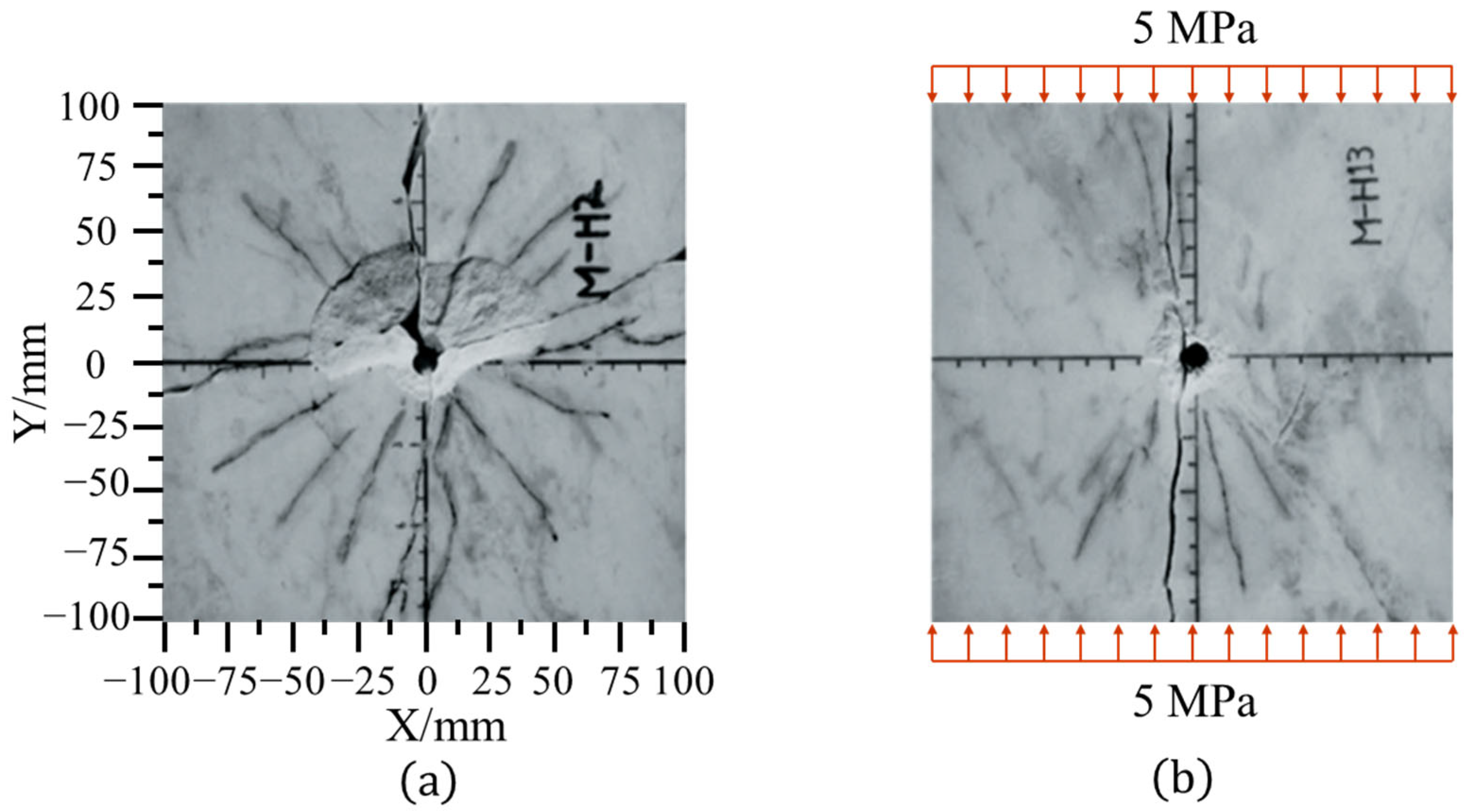
Jung et al. [20] performed single-hole blasting experiments on marble slabs in the laboratory. Marble slabs are loaded under the uniaxial stress of 5 MPa and without prestress. In these experiments, the dimension of the marble slab was 200 mm × 200 mm × 23 mm. The radius of the center borehole in the marble slab was 4 mm. A high-precision detonator was used for blasting and the density, modulus of elasticity, Poisson’s ratio, and tensile strength of the marble were 2625   k g / m 3 , 20.7 GPa, 0.12 and 6.2 MPa, respectively. The blast-induced rock-fracture modes are listed in Figure 5.
Numerical simulations were performed using MPM and compared with single-hole blasting experiments conducted by Jung et al. [20]. The dimensions, rock parameters, and prestress in numerical models are consistent with the experiment setup. The numerical rock-fracture modes caused by blasting without prestress and under uniaxial prestress are visualized in Figure 6, respectively. The experimental and numerical results demonstrated that the blast-induced cracks expanded radially around the borehole without applying prestress. However, when a 5 MPa uniaxial prestress was applied, the crack extension direction was consistent with the direction of the prestress, and the prestress inhibited the crack extension in the direction perpendicular to it. Notably, the longest crack observed in the numerical simulation is also consistent with the crack observed in the experiment. These indicate that the MPM and numerical model are suitable for simulating rock fracture caused by blasting.

4. Numerical Simulation Results

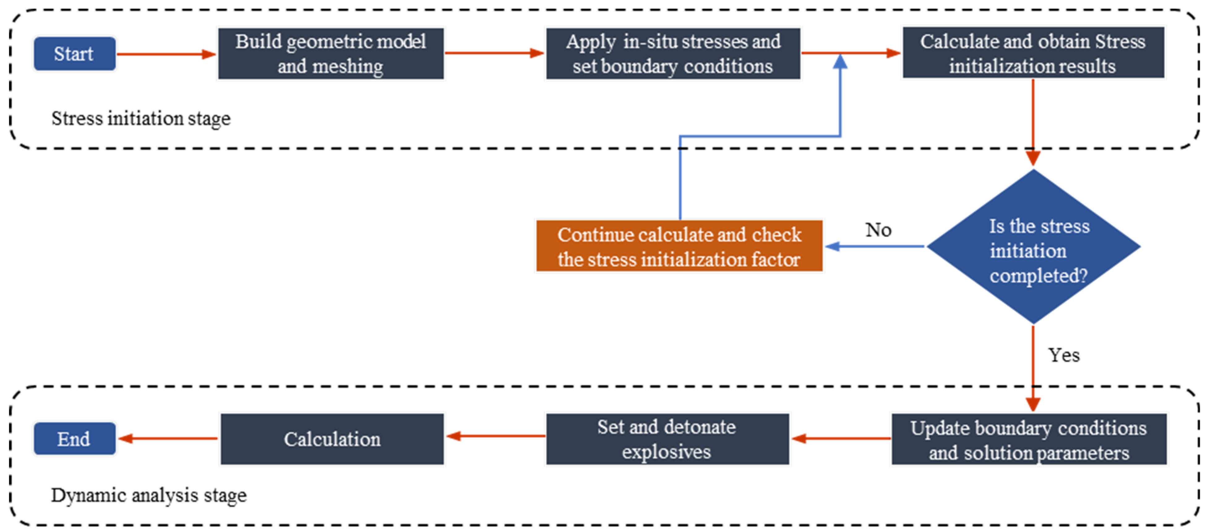
Generally, the numerical simulation of rock blasting under in-situ stress can be divided into static and dynamic phases. The static phase is the in-situ stress field simulation phase, known as the stress initialization phase, and the dynamic phase is the numerical simulation of the blasting process. The whole simulation process is shown in Figure 7.
The numerical models were employed in the simulations, which were conducted using the MPAS code (material point analysis system developed by the authors), an explicit material point method dynamic calculation program designed in C++. Furthermore, the program has already yielded some positive outcomes [35,53].

4.1. Stress Initialization

In deep-rock engineering, the in-situ stress state is significant, as it plays a pivotal role in the dynamic response behavior of rocks. Consequently, stress initialization represents a crucial initial step in the dynamic response simulation of rock masses in a high in-situ stress field [54]. The dynamic relaxation method is often used for its cost-effectiveness and ease of implementation. This method has characteristics of the explicit dynamic procedure of the material point method by introducing fictitious mass and viscous damping [55].
The dynamic equilibrium equation with fictitious mass and viscous damping is as follows:
P t = M a t + C v t + K d t
Using static loads to substitute for dynamic loads, the above equation can be rewritten as follows:
P K d t = M a t + C v t
where M is the fictitious mass and C is the artificial damping. v t and a t are the velocity and acceleration at time step t , respectively.
The left two terms of Equation (22) can be assumed as an unbalanced force R t at time step t , and Equation (22) can be written as Equation (23).
R t = M a t + C v t
The time increment step is t . Nodal velocity using the finite-difference method can be written as follows:
v t = 1 2 v t + t 2 + v t t 2
The acceleration can be obtained by linear interpolation of the velocity, as in Equation (25).
a t = 1 t v t + t 2 v t t 2
Substituting Equations (24) and (25) into Equation (23), the unbalanced force can be written as follows:
R t = 1 t M v t + t 2 v t t 2 + 1 2 C v t + t 2 + v t t 2
Therefore, Equation (26) can be rewritten in terms of the velocity at time t + t / 2 as follows:
v t + t 2 = 1 t M + 1 2 C 1 1 t 1 2 C v t t 2 + 1 t M + 1 2 C 1 R t
Assuming the viscous damping coefficient β as follows:
β = C t 2 M
After substituting Equation (28) into Equation (27), Equation (27) yields as follows:
v t + t 2 = 1 β 1 + β v t t 2 + 1 1 + β t M R t
To bring the system to a state of static equilibrium, reduce the unbalanced force factor to R t = M a t , then the velocity update equation becomes as follows:
v t + t 2 = 1 β 1 + β v t t 2 + 1 1 + β a t t
The critical viscous damping coefficient β is related to the model self-oscillation frequency ω , which can be obtained by numerical simulation, and the completion of the stress initialization phase is determined by the static identification condition Equation (31).
K F = F e x t + F i n t / F i n t < α F K E = E K / W e x t < α E
where K F is the parameter of the unbalanced force of the system, K E is the kinetic energy parameters of the system, F e x t and F i n t are nodal external and nodal internal forces, respectively, E K is the total kinetic energy of the system, and W e x t is the work of the nodal external force. When the system is in static equilibrium, K F and K E should be less than the constants α F and α E , setting as 0.01.
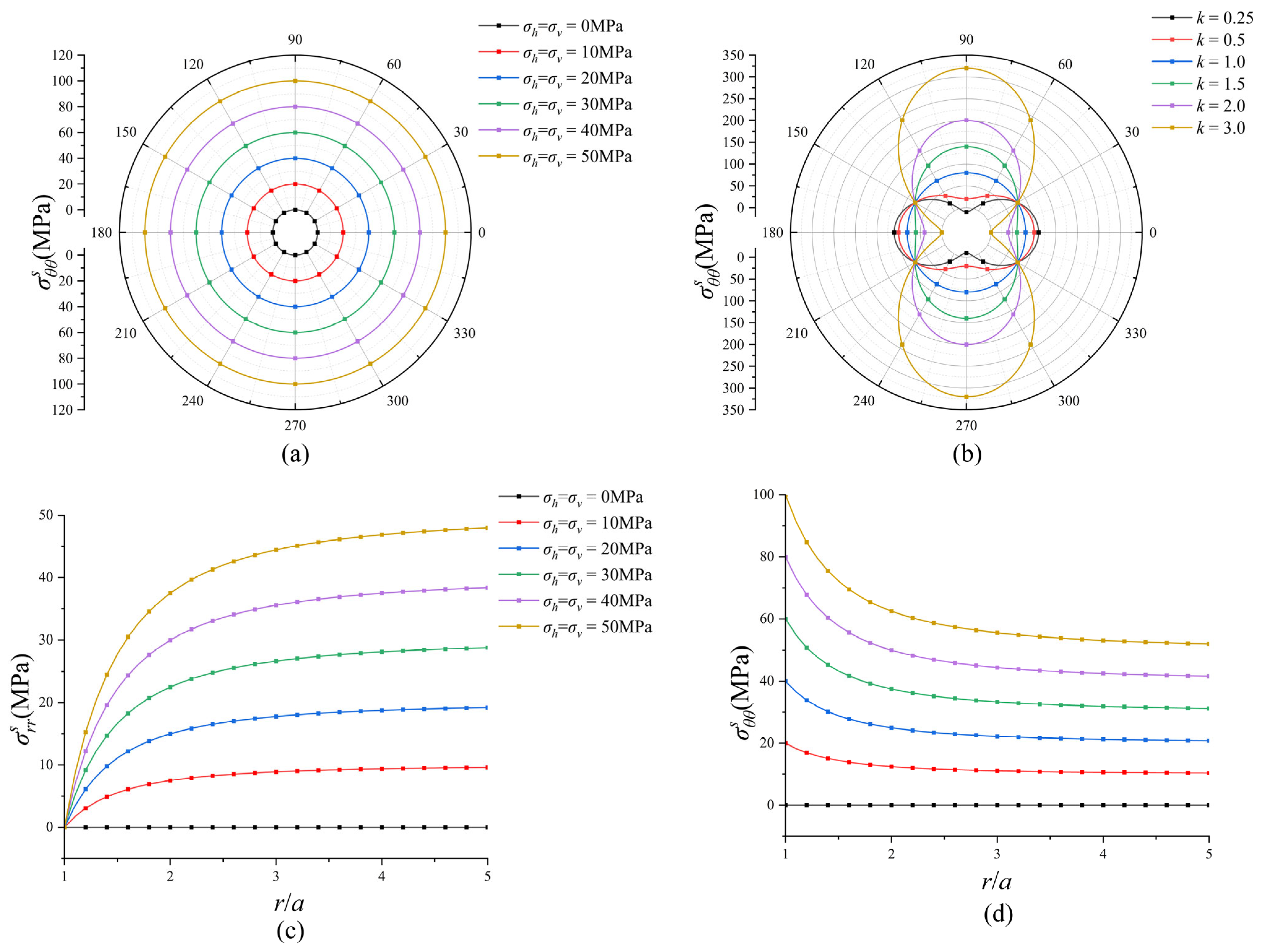
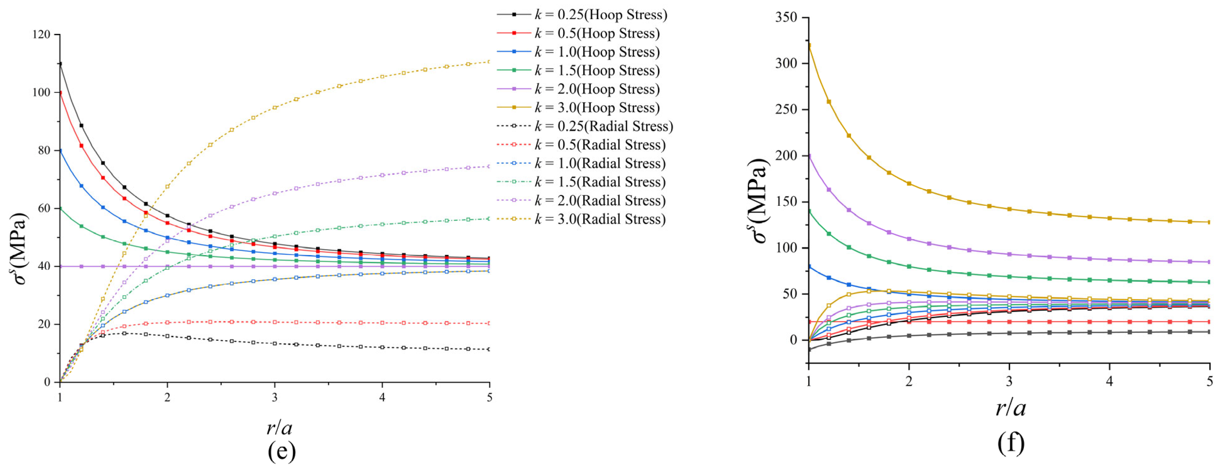
According to Equation (13), the stress distribution on the borehole wall and the variation in stress with increasing distance from the borehole can be obtained. As shown in Figure 8a,b, the circumferential stress distribution on the borehole wall for equiaxial pressure and different lateral pressures, respectively. Figure 8c–f shows the variation in stress as a function of distance from the borehole.
In the case of equiaxial pressure, from Figure 8a, circularly distributed circumferential compressive stress is generated on the borehole wall, which tends to increase in-situ stress levels. In the context of varying lateral pressure conditions, tensile stress is observed in the vertical direction of the borehole wall when k = 0.25. Conversely, when k > 0.25, circumferential stress is identified as compressive stress. Furthermore, with the increase in k, the circumferential compressive stress in the vertical direction is observed to increase more significantly compared to the horizontal direction.
From Figure 8c, radial stress around the borehole increases as the distance from the borehole rises in the case of equiaxial pressure. Conversely, in Figure 8d, radial stress around the borehole diminishes as the distance from the borehole increases. Eventually, the circumferential and radial stress converge with in-situ stress. Circumferential tensile stresses primarily influence the growth of cracks, and the circumferential compressive stress intensifies with the increment of in-situ stress. It can thus be deduced that higher in-situ stress has the potential to impede crack propagation.
In the case of different lateral pressures, as depicted in Figure 8e,f, in the horizontal direction, when k < 1.0 , the horizontal stress is less than the vertical stress, with the increase in distance from the borehole the circumferential stress decreases until it converges to the value of vertical stress. Simultaneously, the radial stress increases and then decreases until it aligns with the horizontal stress in the horizontal direction. When k > 1.0 and the distance from the borehole increases, the circumferential stress increases and then decreases until it matches the vertical stress value, and the radial stress gradually increases and converges to the horizontal stress value. In the vertical direction, the circumferential stress converges to the horizontal stress, while the radial stress converges to the vertical stress.
Numerical simulation was carried out based on the model shown in Figure 4, and the radial stress and circumferential stress distributions are plotted after stress initialization. Numerical outcomes presented in Figure 9 correspond to cases of σ h   = σ v = 10   M P a , σ h   = σ v = 40   M P a , k = 0.25 ,   a n d   k = 3.0 . From Figure 9a, at a certain distance from the borehole, the distribution of radial stress and circumferential stress is circular when σ h = σ v = 10   M P a , which means under the equiaxial pressure condition, the distribution of radial stress and annular stress is basically identical. From Figure 9d, when k = 3.0, the radial stress exhibits a nonlinear increase from the vertical to the horizontal direction, and the annular stress increases nonlinearly from the horizontal to the vertical direction. The results of the stress distribution analysis are in accordance with the theoretical analysis, thereby confirming the reliability of the stress initialization method employed.

4.2. Single-Hole Blasting with In-Situ Stress

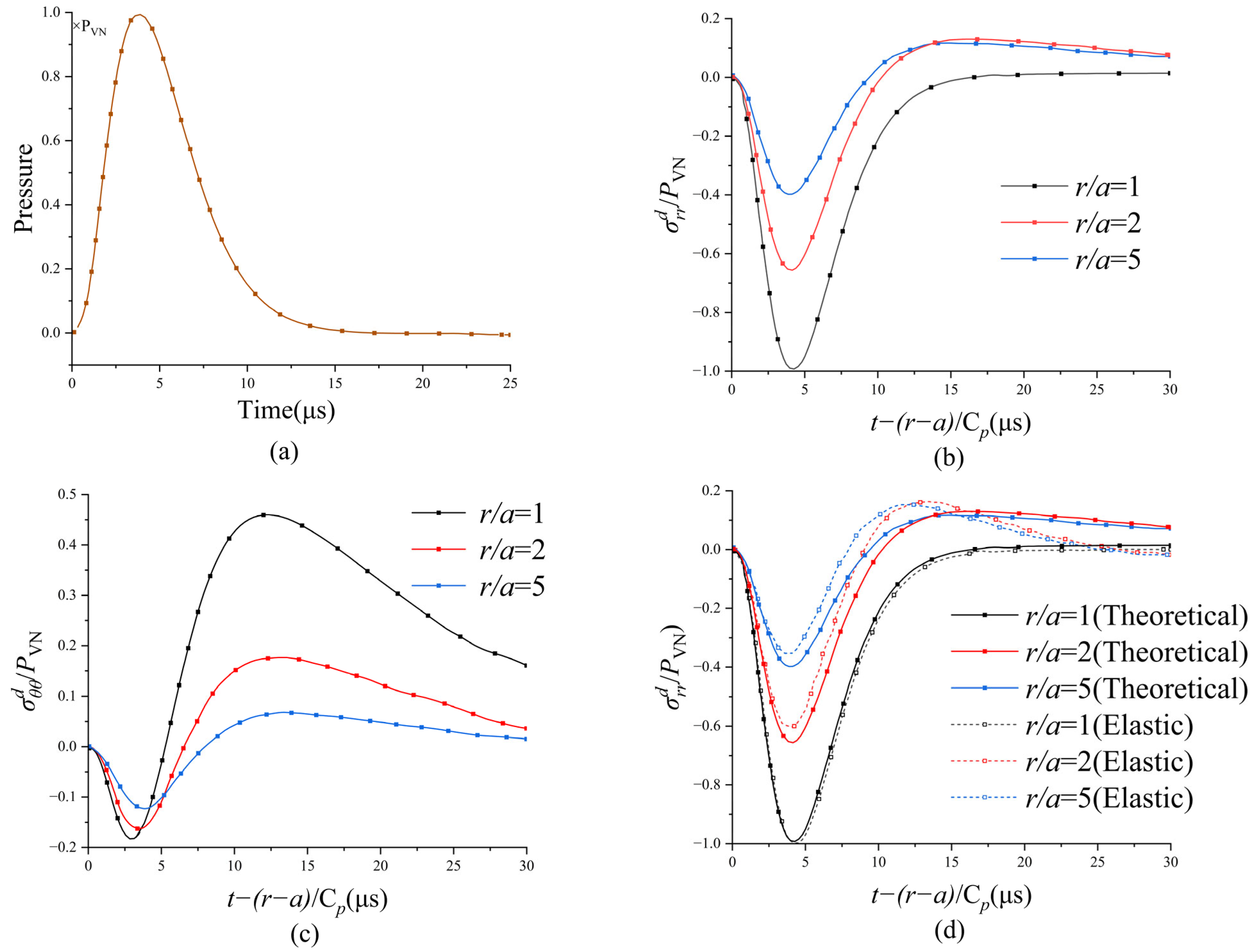
After stress initialization, the explosives can be detonated, and the boundary conditions should be changed to a reflection-free boundary. The theoretical analysis of the blasting-induced stress component is shown in Figure 10. As the stress wave propagates, the circumferential stress transitions from compressive to tensile stress, resulting in radial cracks within a specific range around the borehole. Figure 10d shows the stress histories derived from theoretical and numerical investigations. The numerical calculation results of the elastic material in compression and tension conditions at the wall of the borehole are incredibly close to the theoretical calculation results. In contrast, in the vicinity of the borehole, due to the large deformation characteristics of the rock-blasting problem, the results of the elastic model based on the small deformation theory make a certain degree of error with the theoretical calculation results. The overall trend is in agreement, which verifies the accuracy of the theoretical and numerical calculations.
In the stress wave propagation and stress wave reflection problems, to simulate an infinite range of stress wave propagation in a finite computational region, it is necessary to set the boundary condition as a reflection-free boundary, and the boundary force σ b o n d is introduced to replace the far-area-acting stress σ i n f in the MPM [56]. In the two-dimensional case, the boundary force is given by the displacement continuity condition. It can be expressed as
σ n = ρ c p v n σ t = ρ c s v s
where σ n is the normal stress, σ t is the tangential stress, ρ   is the current material density, c p and c s are the compression and shear wave speeds respectively, v n is the normal vibrational velocity, and v s is tangential vibrational velocity.
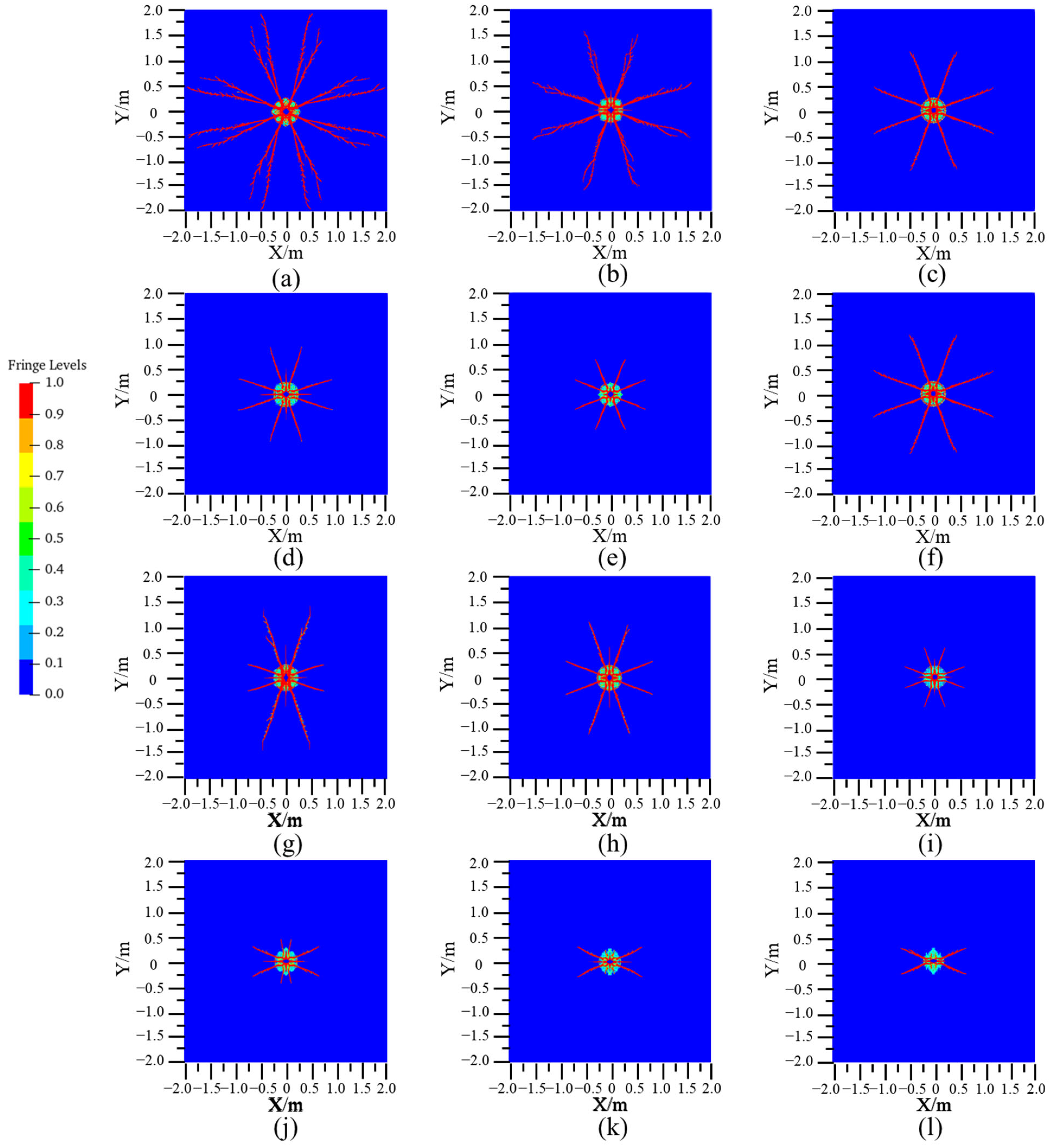
Figure 11a–f shows the numerical simulation results under equiaxial conditions. It is evident that the in-situ stress significantly influences the propagation of cracks, and the lengths of cracks are almost the same in the horizontal and vertical directions under equiaxial conditions. The maximum crack length is generated in the absence of in-situ stress. When the ground stress σ h = σ v = 10 MPa, the crack length decreases obviously. Subsequently, with the increase in the in-situ stress from 10 MPa to 50 MPa, the crack length decreases gradually, and the crack is minimal when the in-situ stress reaches 50 MPa.
Figure 11g–l shows the numerical simulation results of blasting with different lateral pressure coefficients, at a burial depth of 1500 m with the vertical pressure σ v = 40 MPa. The inhibitory effect of the in-situ stress on the crack extension is enhanced when the lateral pressure coefficient k is increased from 0.25 to 3.0, and the direction of the longest crack coincides with the direction of the maximum in-situ stress. When the lateral pressure coefficient k is less than 1.0, the horizontal in-situ stress is less than the vertical in-situ stress, resulting in a shorter maximum crack length horizontally compared to vertically. The disparity between crack lengths in the two directions decreases when k increases. However, when k exceeds 1.0, the crack length in the vertical direction is significantly reduced; it decreases with the increase in the lateral pressure coefficient and vertical cracks are difficult to form when k = 2.0 and k = 3.0 ; the results demonstrate that the in-situ stress perpendicular to the crack growth direction significantly inhibits crack extension. Meanwhile, the horizontal crack length changes slightly with the increase in the lateral pressure coefficient.

4.3. Discussion

The propagation of cracks in the process of blast-induced rock fracture is closely related to the in-situ stress level and the above theoretical and numerical simulation results can provide some guidance for the design of deep-rock-blast engineering.
The results of the above studies show that the in-situ stress significantly inhibits crack extension, and the crack extension length decreases significantly with increasing ground stress. If the design of deep-rock blasting with high in-situ stresses is identical to that of shallow-rock blasting, cracks may not be able to connect between adjacent boreholes, which is not conducive to rock fragmentation and the formation of excavation profiles. Consequently, in the design of deep-rock blasting, the explosive payload can be increased in accordance with the desired outcome, while the hole spacing can be reduced to enhance the fragmentation of the rock, improve the quality of the excavation profile, and achieve more optimal blasting results.
Under unequal horizontal and vertical stress, the direction of the longest crack produced by blasting coincides with the maximum in-situ stress, since the crack extension is largely inhibited by in-situ stresses perpendicular to the crack growth direction. Consequently, the configuration of boreholes aligned with the direction of the maximum in-situ stress is more conducive to the interconnection of cracks between boreholes. In deep-tunnel blasting, the configuration direction of contour boreholes is constrained by the location of the tunnel contour and is not readily amenable to modification. However, the cutting holes can be arranged toward the maximum in-situ stress, thus facilitating the connection of cracks created by blasting adjacent holes and the formation of cavities. The cavities will provide a new free surface for subsequent rock blasting, facilitating the reflection of the blast-stress wave to promote rock fracture.

5. Conclusions

The material point method combining CPDI and GIMP was adopted for the numerical simulation of deep-rock blasting, and a simple theoretical analysis was conducted. A coupling method can provide a uniform blasting pressure and overcome tensile instability. A good agreement was achieved between the simulation and experimental results. From this study, the following conclusions are obtained.
  • In the stress initialization stage, the dynamic relaxation method is adopted in the material point method to simulate the in-situ stress field and in-situ stress field results obtained by numerical simulation, consistent with theoretical results. The dynamic relaxation method is straightforward and cost-effective in the display dynamics software and only requires the introduction of a damping coefficient in the velocity update equation.
  • The in-situ stress significantly inhibits the crack extension produced by rock blasting, and the maximum crack length decreases considerably with the increase in in-situ stress due to the significant difference in the level of in-situ stress between the deep and shallow rock mass. Adjusting borehole spacing is advised to ensure complete crack extension to optimize rock fragmentation and excavation profile quality in deep-rock masses under high in-situ stress.
  • Under unequal horizontal and vertical stress, the orientation of the most extended cracks produced by blasting aligns with the direction of the maximum in-situ stress. Consequently, the arrangement of boreholes along the direction of the maximum in-situ stress is more conducive to promoting the connection of cracks produced between adjacent boreholes after blasting.

Author Contributions

Methodology, H.X.; Software, Y.W.; Validation, W.G.; Formal analysis, M.W.; Investigation, H.X.; Resources, H.X., W.G. and M.Z.; Data curation, M.Z.; Writing—original draft, H.X.; Writing—review & editing, M.W.; Supervision, M.W. and J.S.; Project administration, M.W. All authors have read and agreed to the published version of the manuscript.

Funding

This research was funded by the National Natural Science Foundation of China (grant number 12272247), National Key Project (grant number GJXM92579), and State Key Laboratory of Precision Blasting and Hubei Key Laboratory of Blasting Engineering, Jianghan University (grant number PBSKL2022B06).

Data Availability Statement

The data presented in this study are available on request from the corresponding author.

Conflicts of Interest

The authors declare no conflict of interest.

References

  1. Feng, X.; Yao, Z.; Li, S.; Wu, S.; Yang, C.; Guo, H.; Zhong, S. In Situ Observation of Hard Surrounding Rock Displacement at 2400-m-Deep Tunnels. Rock Mech. Rock Eng. 2018, 51, 873–892. [Google Scholar] [CrossRef]
  2. Wagner, H. Deep Mining: A Rock Engineering Challenge. Rock Mech. Rock Eng. 2019, 52, 1417–1446. [Google Scholar] [CrossRef]
  3. Zhou, J.; Li, X.; Mitri, H.S. Evaluation method of rockburst: State-of-the-art literature review. Tunn. Undergr. Space Technol. 2018, 81, 632–659. [Google Scholar] [CrossRef]
  4. Sousa, L.M. The influence of the characteristics of quartz and mineral deterioration on the strength of granitic dimensional stones. Environ. Earth Sci. 2013, 69, 1333–1346. [Google Scholar] [CrossRef]
  5. Barton, N. Shear strength criteria for rock, rock joints, rockfill and rock masses: Problems and some solutions. J. Rock Mech. Geotech. Eng. 2013, 5, 249–261. [Google Scholar] [CrossRef]
  6. Barton, N. Review of a new shear-strength criterion for rock joints. Eng. Geol. 1973, 7, 287–332. [Google Scholar] [CrossRef]
  7. Koca, T.K.; Köken, E. A combined application of two soft computing algorithms for weathering degree quantification of andesitic rocks. Appl. Comput. Geosci. 2022, 16, 100101. [Google Scholar] [CrossRef]
  8. Bhatawdekar, R.M.; Edy, M.T.; Danial, J.A. Building information model for drilling and blasting for tropically weathered rock. J. Mines Met. Fuels 2022, 67, 494–500. [Google Scholar]
  9. Thuro, K.; Plinninger, R. Hard rock tunnel boring, cutting, drilling and blasting: Rock parameters for excavatability. In Proceedings of the ISRM Congress, Sandton, South Africa, 8–12 September 2003; p. ISRM–10CONGRESS-2003-2212. [Google Scholar]
  10. Xie, H.; Peng, S.; He, M. Basic Theory and Engineering Practice in Deep Mining; Science Press: Beijing, China, 2006. [Google Scholar]
  11. Zhu, Z. Evaluation of the range of horizontal stresses in the earth’s upper crust by using a collinear crack model. J. Appl. Geophys. 2013, 88, 114–121. [Google Scholar] [CrossRef]
  12. Lucier, A.M.; Zoback, M.D.; Heesakkers, V.; Reches, Z.E.; Murphy, S.K. Constraining the far-field in situ stress state near a deep South African gold mine. Int. J. Rock Mech. Min. Sci. 2009, 46, 555–567. [Google Scholar] [CrossRef]
  13. Pesch, R.; Robertson, A. Drilling and blasting for underground space. In Proceedings of the EXPLO Conference, Wollongong, Australia, 3–4 September 2007; pp. 189–193. [Google Scholar]
  14. Zuo, J.; Yang, R.; Gong, M.; Ma, X.; Wang, Y. Fracture characteristics of iron ore under uncoupled blast loading. Int. J. Min. Sci. Technol. 2022, 32, 657–667. [Google Scholar] [CrossRef]
  15. AyalaCarcedo, F. Drilling and Blasting of Rocks; Routledge: London, UK, 2017. [Google Scholar]
  16. Kaiser, P.K.; Kim, B.-H. Characterization of Strength of Intact Brittle Rock Considering Confinement-Dependent Failure Processes. Rock Mech. Rock Eng. 2015, 48, 107–119. [Google Scholar] [CrossRef]
  17. Lu, W.; Chen, M.; Geng, X.; Shu, D.; Zhou, C. A study of excavation sequence and contour blasting method for underground powerhouses of hydropower stations. Tunn. Undergr. Space Technol. 2012, 29, 31–39. [Google Scholar] [CrossRef]
  18. Kutter, H.; Fairhurst, C. On the fracture process in blasting. Int. J. Rock Mech. Min. Sci. Geomech. Abstr. 1971, 8, 181–202. [Google Scholar] [CrossRef]
  19. Nicholls, H.R.; Duvall, W.I. Presplitting Rock in the Presence of a Static Stress Field; US Department of the Interior, Bureau of Mines: Pittsburgh, PA, USA, 1966; Volume 6843. [Google Scholar]
  20. Jung, W.J.; Utagawa, M.; Ogata, Y.; Seto, M.; Katsuyama, K.; Miyake, A.; Ogawa, T. Effects of rock pressure on crack generation during tunnel blasting. J. Jpn. Explos. Soc. 2001, 62, 138–146. [Google Scholar]
  21. Yang, L.; Yang, R.; Hu, P.; Song, Y. Experimental study on the effect of initial compression-stress field on blast-induced crack behaviors. J. China Coal Soc. 2013, 38, 404–410. [Google Scholar]
  22. Shu, Y.; Zhu, Z.; Wang, M.; Ying, P.; Wang, F.; Wan, D.; Li, X.; Gao, W. A plastic damage constitutive model for rock-like material focusing on the hydrostatic pressure induced damage and the interaction of tensile and shear damages under impact and blast loads. Comput. Geotech. 2022, 150, 104921. [Google Scholar] [CrossRef]
  23. Tao, J.; Yang, X.; Li, H.; Zhou, J.; Qi, S.; Lu, G. Numerical investigation of blast-induced rock fragmentation. Comput. Geotech. 2020, 128, 103846. [Google Scholar] [CrossRef]
  24. Dai, J.; Yang, J.; Yao, C.; Hu, Y.; Zhang, X.; Jiang, Q.; Zhou, C. Study on the mechanism of displacement mutation for jointed rock slopes during blasting excavation. Int. J. Rock Mech. Min. Sci. 2022, 150, 105032. [Google Scholar] [CrossRef]
  25. Zhang, Z.; Gao, W.; Li, K.; Li, B. Numerical simulation of rock mass blasting using particle flow code and particle expansion loading algorithm. Simul. Model. Pract. Theory 2020, 104, 102119. [Google Scholar] [CrossRef]
  26. Zhu, F.; Zhao, J. Peridynamic modelling of blasting induced rock fractures. J. Mech. Phys. Solids 2021, 153, 104469. [Google Scholar] [CrossRef]
  27. Bendezu, M.A.L.; Romanel, C.; Roehl, D. Finite element analysis of blast-induced fracture propagation in hard rocks. Comput. Struct. 2017, 182, 1–13. [Google Scholar] [CrossRef]
  28. Fakhimi, A.; Lanari, M. DEM-SPH simulation of rock blasting. Comput. Geotech. 2014, 55, 158–164. [Google Scholar] [CrossRef]
  29. Koneshwaran, S.; Thambiratnam, D.P.; Gallage, C. Blast Response of Segmented Bored Tunnel using Coupled SPH–FE Method. Structures 2015, 2, 58–71. [Google Scholar] [CrossRef]
  30. Sulsky, D.; Chen, Z.; Schreyer, H.L. A particle method for history-dependent materials. Comput. Methods Appl. Mech. Eng. 1994, 118, 179–196. [Google Scholar] [CrossRef]
  31. Sulsky, D.; Zhou, S.-J.; Schreyer, H.L. Application of a particle-in-cell method to solid mechanics. Comput. Phys. Commun. 1995, 87, 236–252. [Google Scholar] [CrossRef]
  32. Bardenhagen, S.G.; Kober, E.M. The generalized interpolation material point method. CMES-Comput. Model. Eng. Sci. 2004, 5, 477–495. [Google Scholar]
  33. Sadeghirad, A.; Brannon, R.M.; Burghardt, J. A convected particle domain interpolation technique to extend applicability of the material point method for problems involving massive deformations. Int. J. Numer. Methods Eng. 2011, 86, 1435–1456. [Google Scholar] [CrossRef]
  34. Sadeghirad, A.; Brannon, R.M.; Guilkey, J.E. Second-order convected particle domain interpolation (CPDI2) with enrichment for weak discontinuities at material interfaces. Int. J. Numer. Methods Eng. 2013, 95, 928–952. [Google Scholar] [CrossRef]
  35. Wan, D.; Wang, M.; Zhu, Z.; Wang, F.; Zhou, L.; Liu, R.; Gao, W.; Shu, Y.; Xiao, H. Coupled GIMP and CPDI material point method in modelling blast-induced three-dimensional rock fracture. Int. J. Min. Sci. Technol. 2022, 32, 1097–1114. [Google Scholar] [CrossRef]
  36. An, H.M.; Liu, H.Y.; Han, H.; Zheng, X.; Wang, X.G. Hybrid finite-discrete element modelling of dynamic fracture and resultant fragment casting and muck-piling by rock blast. Comput. Geotech. 2017, 81, 322–345. [Google Scholar] [CrossRef]
  37. Johnson, G.R.; Holmquist, T.J. An improved computational constitutive model for brittle materials. In Proceedings of the AIP Conference Proceedings, Colorado Springs, CO, USA, 2–28 July 1994; pp. 981–984. [Google Scholar]
  38. Brackbill, J.U.; Ruppel, H.M. FLIP: A method for adaptively zoned, particle-in-cell calculations of fluid flows in two dimensions. J. Comput. Phys. 1986, 65, 314–343. [Google Scholar] [CrossRef]
  39. Kirsch, E.G. Die Theorie der Elastizit t und die Bed rfnisse der Festigkeitslehre. Zeitshrift Vereines Dtsch. Ingenieure 1898, 42, 797–807. [Google Scholar]
  40. Blair, D.P. A comparison of Heelan and exact solutions for seismic radiation from a short cylindrical charge. Geophysics 2007, 72, E33–E41. [Google Scholar] [CrossRef]
  41. Hustrulid, W.A. Blasting Principles for Open Pit Mining; A.A. Balkema Publisher: Brookfiled, VT, USA, 1999. [Google Scholar]
  42. Miklowitz, J.; Kaul, R.K. The Theory of Elastic Waves and Waveguides. J. Appl. Mech. 1979, 46, 969. [Google Scholar] [CrossRef]
  43. Durbin, F. Numerical inversion of Laplace transforms: An efficient improvement to Dubner and Abate’s method. Comput. J. 1974, 17, 371–376. [Google Scholar] [CrossRef]
  44. Yue, Z.; Zhou, J.; Feng, C.; Wang, X.; Peng, L.; Cong, J. Coupling of material point and continuum discontinuum element methods for simulating blast-induced fractures in rock. Comput. Geotech. 2022, 144, 104629. [Google Scholar] [CrossRef]
  45. Zhang, X.; Chen, Z.; Liu, Y. The Material Point Method: A Continuum-Based Particle Method for Extreme Loading Cases; Academic Press: New York, NY, USA, 2016. [Google Scholar]
  46. Kury, J.; Hornig, H.; Lee, E.; McDonnel, J.; Ornellas, D.; Finger, M.; Strange, F.; Wilkins, M. Metal acceleration by chemical explosives. In Proceedings of the Fourth Symposium (International) on Detonation, White Oak, MD, USA, 12–15 October 1965; pp. 3–13. [Google Scholar]
  47. Banadaki, M.M.D.; Mohanty, B. Numerical simulation of stress wave induced fractures in rock. Int. J. Impact Eng. 2012, 40–41, 16–25. [Google Scholar] [CrossRef]
  48. Zhang, X.; Hao, H.; Ma, G. Dynamic material model of annealed soda-lime glass. Int. J. Impact Eng. 2015, 77, 108–119. [Google Scholar] [CrossRef]
  49. Wang, J.; Yin, Y.; Esmaieli, K. Numerical simulations of rock blasting damage based on laboratory-scale experiments. J. Geophys. Eng. 2018, 15, 2399–2417. [Google Scholar] [CrossRef]
  50. Xie, L.; Zhang, Q.; Gu, J.; Lu, W.; Yang, S.; Jing, H.; Wang, Z. Damage evolution mechanism in production blasting excavation under different stress fields. Simul. Model. Pract. Theory 2019, 97, 101969. [Google Scholar] [CrossRef]
  51. Yang, J.; Wu, Z.; Sun, W.; Yao, C.; Wang, Q. Numerical simulation on radiation and energy of blast-induced seismic waves in deep rock masses. J. Cent. South Univ. 2022, 29, 645–662. [Google Scholar] [CrossRef]
  52. Ai, H.A.; Ahrens, T.J. Simulation of dynamic response of granite: A numerical approach of shock-induced damage beneath impact craters. Int. J. Impact Eng. 2006, 33, 1–10. [Google Scholar] [CrossRef]
  53. Wan, D.; Wang, M.; Zhu, Z.; Wang, Y.; Xiao, H.; Gao, W. A coupled model of asymmetric GIMP and tetrahedron CPDI based on the penalty contact algorithm for simulating dynamic rock splitting. Int. J. Rock Mech. Min. Sci. 2023, 170, 105483. [Google Scholar] [CrossRef]
  54. Yang, J.-C.; Liu, K.-W.; Li, X.-D.; Liu, Z.-X. Stress initialization methods for dynamic numerical simulation of rock mass with high in-situ stress. J. Cent. South Univ. 2020, 27, 3149–3162. [Google Scholar] [CrossRef]
  55. Kilic, B.; Madenci, E. An adaptive dynamic relaxation method for quasi-static simulations using the peridynamic theory. Theor. Appl. Fract. Mech. 2010, 53, 194–204. [Google Scholar] [CrossRef]
  56. Shan, Z.; Liao, Z.; Dong, Y.; Wang, D.; Cui, L. Implementation of absorbing boundary conditions in dynamic simulation of the material point method. J. Zhejiang Univ.-Sci. A 2021, 22, 870–881. [Google Scholar] [CrossRef]
Figure 1. Drilling and blasting: the mechanism of blasting and rock fragmentation.
Processes 12 01048 g001
Figure 2. Sketch of a discrete body of MPM.
Processes 12 01048 g002
Figure 3. Geometric models (a) the model under the combination of dynamic and static loads (b) the model under static loads; (c) the model under blasting loads.
Processes 12 01048 g003
Figure 4. The numerical models: (a) model schematic (b) overall discrete model (c) discrete model of the localized borehole.
Processes 12 01048 g004
Figure 5. Experimental results: (a) Without prestress; (b) With a uniaxial stress of 5 MPa.
Processes 12 01048 g005
Figure 6. Numerical results: (a) Without prestress; (b) With a uniaxial stress of 5 MPa.
Processes 12 01048 g006
Figure 7. Flow chart of the stress initialization and the dynamic analysis.
Processes 12 01048 g007
Figure 8. The stress distribution around the borehole: (a) under equiaxial pressure conditions, (b) under anisotropic pressure conditions, (c) Radial stresses under equiaxial pressure conditions, (d) Circumferential stresses under equiaxial pressure conditions, (e) Stresses in the horizontal direction, and (f) Stresses in the vertical direction.
Processes 12 01048 g008aProcesses 12 01048 g008b
Figure 9. Results of the stress initialization: (a) σ h = σ v = 10   M P a , (b) σ h = σ v = 40   M P a , (c) k = 0.25 , and (d) k = 3.0 .
Processes 12 01048 g009
Figure 10. Stress histories under blasting: (a) The blasting stress wave, (b) Radial stresses, (c) Circumferential stresses, and (d) Comparison of theoretical and numerical simulation results.
Processes 12 01048 g010
Figure 11. Numerical simulation results of single-borehole blasting: (a) σh = σv = 0 MPa, (b) σh = σv = 10 MPa, (c) σh = σv = 20 MPa, (d) σh = σv = 30 MPa, (e) σh = σv = 40 MPa, (f) σh = σv = 50 MPa, (g) σh = 25 σv = 10 MPa, (h) σh = 0.5 σv = 20 MPa, (i) σh = σv = 40 MPa, (j) σh = 1.5 σv = 60 MPa, (k) σh = 2.0 σv = 80 MPa, and (l) σh = 3.0 σv = 120 MPa.
Processes 12 01048 g011
Table 1. The Parameters of JWL EOS of PETN.
MaterialA (kPa)B (kPa)R1R2ωE0 (kJ/m3)
PETN573,100,00020,160,00061.80.287,190,001
Table 2. Parameters of JH-2 model of granite.
ParameterValueParameterValue
ρ (g/cm3)
E (MPa)
2.66
51,188.28
S m f
σ H E L (MPa)
0.25
4500
υ0.16818 p H E L (MPa)3700
A0.76Beta0.5
B0.25 D 1 0.4
C0.005 D 2 0.9
M0.62 K 1 (GPa)25.7
ε ˙ 0 (s−1)1 K 2 (GPa)−4500
T (MPa)54 K 3 (GPa)300,000
Disclaimer/Publisher’s Note: The statements, opinions and data contained in all publications are solely those of the individual author(s) and contributor(s) and not of MDPI and/or the editor(s). MDPI and/or the editor(s) disclaim responsibility for any injury to people or property resulting from any ideas, methods, instructions or products referred to in the content.