Article

H2 Reduction of Na2SO4 to Na2S Based on Dilute-Phase Fluidization

College of Materials Science and Engineering, Xi’an University of Architecture & Technology, Xi’an 710055, China
*
Authors to whom correspondence should be addressed.
Processes 2024, 12(4), 776; https://doi.org/10.3390/pr12040776
Submission received: 14 March 2024 / Revised: 6 April 2024 / Accepted: 7 April 2024 / Published: 12 April 2024
(This article belongs to the Section Materials Processes)

Abstract

:
Sodium sulfate (Na2SO4) is used in the ecofriendly production of sodium sulfide (Na2S) through H2 reduction, thereby facilitating the valorization of Na2SO4. However, studies on this technique remain at the laboratory stage. This paper proposes a novel process involving the external circulation of Na2S in a dilute-phase fluidized system to address the low-temperature eutectic formation between Na2S and Na2SO4 during the H2 reduction of Na2SO4 to Na2S. The process aims to increase the reaction temperature of the Na2SO4 while reducing the volume of the liquid phase formed to prevent sintering blockages and enhance the reduction rate. In a proprietary experimental setup, the H2 reduction process in a dilute-phase fluidized system was investigated. The Na2S/Na2SO4 ratio and reaction temperature were determined to be critical factors influencing the Na2SO4 reduction rate. The melting point of the system increased and the amount of liquid phase produced decreased as the Na2S content was increased to more than 60%. The Na2S–Na2SO4 mixture (mass ratio of 80:20) existed as a solid at the reaction temperature of 740 °C. After roasting for 10 s, the Na2SO4 reduction rate reached 93.7% and the Na2S content in the mixture increased to 98.74%.

1. Introduction

The increasing interest in the valorization of sodium sulfate (Na2SO4) solid waste prompts continuous innovation for environmentally friendly and cost-effective methods [1]. Currently, the most promising strategy is the use of Na2SO4 as a raw material for producing sodium sulfide (Na2S), whereby coal dust is conventionally used as the reducing agent; however, this approach has several limitations. For instance, this method can only produce Na2S with a purity of 60%, which does not meet the high-purity (>92%) Na2S requirements of several industries, and it generates large amounts of CO2 emissions and other pollutants, such as H2S, SO2, NxOy, and dust [2]. In the global pursuit of carbon neutrality, the traditional method of using coal dust to reduce Na2SO4 for producing Na2S is no longer suitable for modern development [3]. Therefore, the development of a new environmentally friendly process that can produce high-purity Na2S is urgently needed.
In recent years, extensive research has been conducted on the H2 reduction of Na2SO4. Although these methods reduce carbon emissions, the research on this process is still at the laboratory stage. During the reduction process, Na2SO4 is gradually depleted and Na2S accumulates. When the system reaches the eutectic temperature, a eutectic layer is formed on the surface of the reactant, thereby hindering the further progress of the reaction. Such a layer impedes the direct contact between the reducing gas and reactants, thereby inhibiting further progression of the reaction. The formation of eutectic material poses a significant obstacle to the industrialization process. It can not only cause the material to lose its fluidization characteristics, affecting its uniform distribution and flow properties, but can also form deposits in reactors or transport pipelines, leading to blockages and difficulties in cleaning [4]. Furthermore, the corrosive nature of the eutectic material may also challenge reactors and other equipment, increasing the frequency of maintenance and equipment replacement [5].
To address this issue, researchers have proposed the addition of catalysts (such as Fe2O3, V2O5) at 600–700 °C to effectively reduce Na2SO4 to Na2S [6]. Although the lower temperature avoids the formation of eutectic materials, this method still faces significant challenges, such as long reaction times, high hydrogen consumption, and most importantly, the components of the catalyst can reduce the quality of Na2S. This necessitates subsequent complex impurity removal processes, and the separation process is extremely difficult, all of which limit the industrial application value of this method. Other researchers have proposed the reaction directly between the reducing gas and molten Na2SO4 at high temperatures to obtain molten Na2S products. Although the subsequent evaporation and crystallization process can produce Na2S of higher purity, the strong corrosiveness of molten Na2S causes serious damage to equipment, and the presence of the liquid phase leads to difficulties in discharging, wall sticking, and other issues, limiting its further research, development, and industrial application [7]. In view of this, researchers need to conduct in-depth studies on the formation mechanism of eutectic materials and develop new catalysts that prevent the formation of eutectic materials without affecting the quality of the product, or to design new process flows to reduce the impact of eutectic materials.
Based on previous research, the challenge in producing Na2S from Na2SO4 lies in the need to increase and control the reaction temperature to accelerate the reduction rate while avoiding sintering, presenting a clear trade-off. Considering the advantages of gas–solid reactions in terms of the mass and heat transfer efficiency, the H2 reduction of Na2SO4 should be carried out with no or minimal liquid phase to achieve a higher reaction rate [8,9,10]. In contrast to the traditional H2 reduction of pure Na2SO4, utilizing a mixture with 80% Na2S and Na2SO4 as the feedstock for the reduction reaction markedly prevents the formation of a liquid phase. This approach addresses the issues of incomplete reactions, extended reaction times, and substandard product qualities, which arise from eutectic formation during the reduction process. Furthermore, the dilute-phase fluidized bed reactor, an effective gas–solid reactor, can enhance the reaction rate without producing a liquid phase. Na2S remains stable under high-temperature reducing conditions, the freshly produced Na2S can be combined with Na2SO4, continuing the reaction as a mixed feedstock until the Na2SO4 is entirely depleted, thus completing the reaction. A study identified the eutectic characteristics of the Na2S–Na2SO4 binary system and the reactivity of its suspended H2 reduction mixture. Na2S is functioned as a nonreactive circulating carrier. When the Na2S content in the binary system exceeds a certain threshold, the formation of a low eutectic product in the system is inhibited, thereby promoting the reduction reaction of Na2SO4 [11]. This paper proposes a novel environmentally friendly process for the reduction roasting of an external circulation ingredient by dilute-phase fluidization.

2. Materials and Methods

2.1. Materials

Na2S reagent with a purity of >95% was purchased from Shanghai Aladdin Biochemical Technology Co., Ltd., Shanghai, China. Analytical-grade Na2SO4 and anhydrous ethanol (C2H6O) reagents were purchased from Sinopharm Group. The N2 and H2 gases had a purity of 99.999%, and deionized water was used as the experimental water. Na2SO4 and Na2S were separately ground in a mortar, passed through a 0.08 mm sieve, leaving a residue of less than 30%, dried, and set aside. The ingredients were mixed with a certain ratio of C2H6O, roasted under a dispersed N2 atmosphere to observe the melting conditions, and then roasted under a suspended H2 atmosphere to calculate the Na2S content and Na2SO4 conversion rate in the roasted sample.

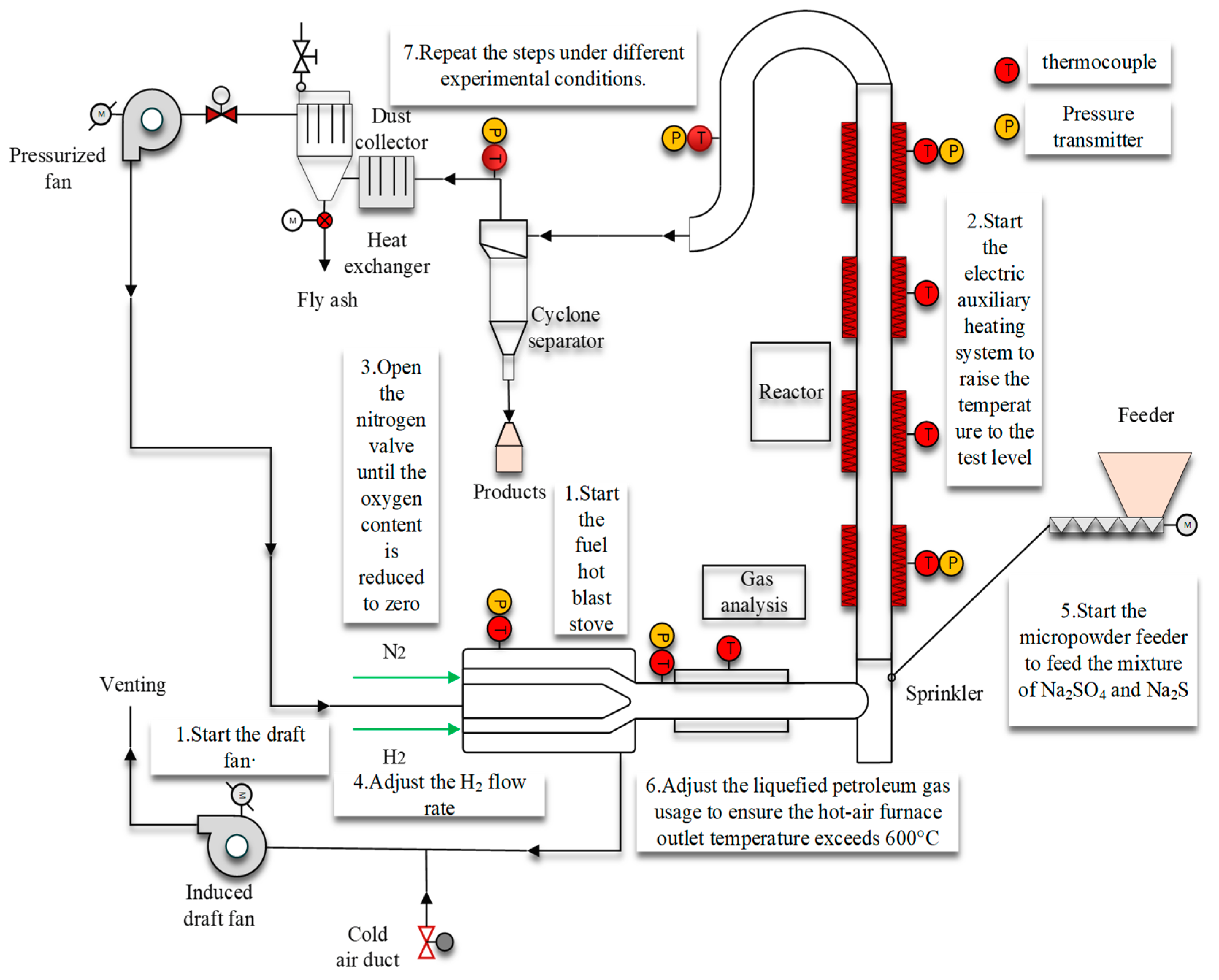
2.2. Experimental Methods

Before the suspended H2 reduction of Na2SO4, the eutectic characteristics of the Na2SO4 and Na2S mixtures at different ratios were determined to establish the appropriate temperature range. A small amount of Na2S–Na2SO4 mixture was placed on a stainless-steel sintered mesh in a homemade atmosphere furnace, heated for 30 min under N2 flow, and cooled in the same atmosphere for the subsequent experiments. Subsequently, the temperature range of 680–740 °C and roasting time of 2–10 s were determined for the dilute-phase fluidization reduction under an H2 atmosphere. The system was operated for 0.5–1.0 h under each condition. Subsequently, the roasted samples were cooled to room temperature, sampled, and labelled for preservation.
In this study, an innovative dilute-phase fluidization system was introduced, which was detailed in the technological diagram (Figure 1), being designed to efficiently produce sodium sulfide (Na2S) through the reduction of sodium sulfate (Na2SO4) with hydrogen gas. The internal draft fan and pressurization fan worked in tandem to ensure the continuous flow of the gaseous medium and uniformity of the reaction process. Key design parameters of the hot blast stove, such as the operating temperature range and thermal efficiency, were meticulously selected to ensure the system operates at optimal reaction temperatures. The reactor’s size and material selection were optimized to maximize the reaction efficiency and product quality, while also considering the long-term durability and safety. The precise control mechanisms of the spreader and micro-powder feeder ensured the uniform distribution and steady supply of solid reactants, which were crucial for the reaction efficiency. The design of the external circulation process included a portion of the produced Na2S together with Na2SO4 as reactants, which were recycled through the feeder, maintaining a high proportion of Na2S within the system and effectively preventing pipe blockage issues caused by the formation of eutectics. The design of the piping took into account the material’s corrosion resistance and high-temperature tolerance, as well as the necessary diameter and length to ensure the smooth transmission of materials and gases. Pressure transmitters and thermocouples, as key monitoring devices in the system, were responsible for real-time monitoring of the pressure and temperature within the system, which was vital for maintaining the stability and safety of the process flow. The design of the cyclone separator, collection barrel, and dust collector optimized the effective separation of the post-reaction products and by-products, thereby enhancing the overall efficiency of the system and the purity of the products. Finally, the integration of the heat exchanger and cold-air duct not only improved the energy utilization efficiency of the system but also controlled the temperature in the process flow, effectively preventing the formation of eutectics due to excessively high temperatures on the pipe walls. These comprehensively designed equipment and process flows demonstrated the technical progress and potential of this study in the field of producing sodium sulfide by reducing sodium sulfate with hydrogen gas.
Figure 1 illustrates the independently developed dilute-phase fluidized gas–solid rapid reaction system, which is a pilot device for the H2 reduction of Na2SO4. The device operates in a temperature range of 0–800 °C with a transport-bed reactor (internal diameter: 80 mm; effective length: 8 m). The experimental procedure was as follows. (1) The centrifugal fan and liquefied petroleum burner of the fuel hot-air furnace were turned on and adjusted to the specific operational parameters, such as the wind speed and amount of liquefied petroleum gas, according to the experimental requirements. (2) When the system temperature approached the set value, the programmable logic controller system and electric auxiliary heating system were turned on to adjust the internal temperature of the reactor to the required experimental temperature. (3) The N2 valve was opened to begin air displacement and closed once the oxygen content in the system reached zero. (4) The H2 pressure-reducing valve was adjusted to achieve the required flow rate for the reaction, ensuring that H2 filled the system. (5) The micropowder feeder was turned on to begin feeding the sample, ensuring that a mixture of Na2SO4 and Na2S entered the reactor. (6) The amount of liquefied petroleum gas was adjusted to increase the outlet temperature of the hot-air furnace to more than 600 °C to preheat the H2. (7) The steps were repeated under different experimental conditions.
Table 1 illustrates the minimum fluidization velocities at various temperatures for a mass ratio of Na2S to Na2SO4 set at 8:2. In the dilute-phase fluidized reduction system, the actual wind speed is typically set to several times the minimum fluidization velocity to ensure the continuous transport of materials. Under the influence of hydrogen, Na2SO4 particles are effectively dispersed within the fluidized furnace, which enhances their reaction with the reducing gas. The minimum fluidization velocity is a crucial design and operational parameter that determines the initiation conditions for the fluidized bed. In the dilute-phase fluidized reduction system, maintaining the minimum fluidization velocity is vital for the effective suspension and transport of materials. Operating wind speeds below the minimum fluidization velocity may result in inadequate particle suspension, reducing the transport efficiency or causing system blockages. Conversely, excessively high wind speeds could shorten the reaction residence time, leading to increased particle wear or higher energy consumption in the system. Given that Na2SO4 and Na2S particles tend to absorb moisture and become sticky, increasing the wind speed can lead to more frequent collisions between the gas and solid phases. This can contribute to the disarray within the suspension calcination system and may cause a substantial amount of reacted material to adhere to the pipe walls, affecting the transport efficiency.
t = L ( V V 0 )
In Equation (1), (t) represents the material residence time, (L) denotes the reactor length, (V0) indicates the minimum fluidization velocity, and (V) signifies the actual wind speed. It was determined that the required wind speeds (V) for residence times (t) of 2, 4, 6, 8, and 10 s are 4.5 m/s, 2.5 m/s, 2.0 m/s, 1.75 m/s, and 1.6 m/s, respectively, by combining the data from Equation (1) and Table 1 with precise calculations of the system parameters. These calculation results visually demonstrated the relationship between the wind speed and residence time, providing a quantitative basis for the optimization of the system design. Furthermore, continuous monitoring of the internal pressure within the system was achieved through a pressure transmitter, maintaining negative pressure transport while preventing material collapse. It was necessary to keep the pressure differential within the reactor pipeline within a safe operational range. These measures ensured the stable operation of the system and the effective reduction of materials.

2.3. Material Characterization

X-ray diffraction (XRD, D/MAX2200 powder X-ray diffractometer with Cu Kα radiation, Rigaku Corporation, The Woodlands, TX, USA, Manufacturer in Japan) was used to detect the major phase changes in the products. Scanning electron microscopy images (GeminiSEM500 field emission scanning electron microscope, Carl Zeiss AG, Oberkochen, Germany) and energy-dispersive spectroscopy maps (UltimMax100 energy spectrometer, Oxford Instruments, Oxford, UK) were used to observe the microstructural changes. The titration (TIT) method followed the JIS K1435 (industrial Na2S) and GB6009-92 (industrial anhydrous Na2SO4) standards to determine the Na2S and Na2SO4 contents, respectively.

3. Results and Discussion

3.1. Eutectic Characteristics of the Na2SO4 and Na2S Mixture

The eutectic characteristics of the Na2S–Na2SO4 system at different temperatures are listed in Table 2. The eutectic temperature of the Na2S–Na2SO4 mixture varied with the component ratio. All the mixtures remained solid at temperatures below 700 °C, and some mixtures started to liquefy at temperatures above 700 °C. Specifically, liquefaction occurred with an Na2S content of 60% at 700 °C; 30%, 40%, 50%, and 60% at 720 °C; and 20–70% at 740 °C. All the mixtures, except the pure Na2SO4 and pure Na2S, exhibited a liquid phase at 760 °C.
When the Na2S proportion in the Na2SO4–Na2S system exceeded 80%, melting did not occur even after heating at 740 °C for 30 min. Therefore, increasing the reaction temperature promoted the reduction of Na2SO4. In particular, Na2S can be mixed with Na2SO4 at a certain ratio as the reactant material to react with H2, increasing the eutectic temperature and maintaining a high reaction rate for the Na2SO4 reduction with minimal or no liquid phase to maximize the reaction rate in the gas–solid reaction system. The resulting Na2S product could be recycled as a reactant for further roasting until all the Na2SO4 content in the system had reacted. Additionally, recycled materials, as solid heat carriers, can improve the thermal stability within the reactor, thereby improving the temperature distribution and thermal stability [12,13].

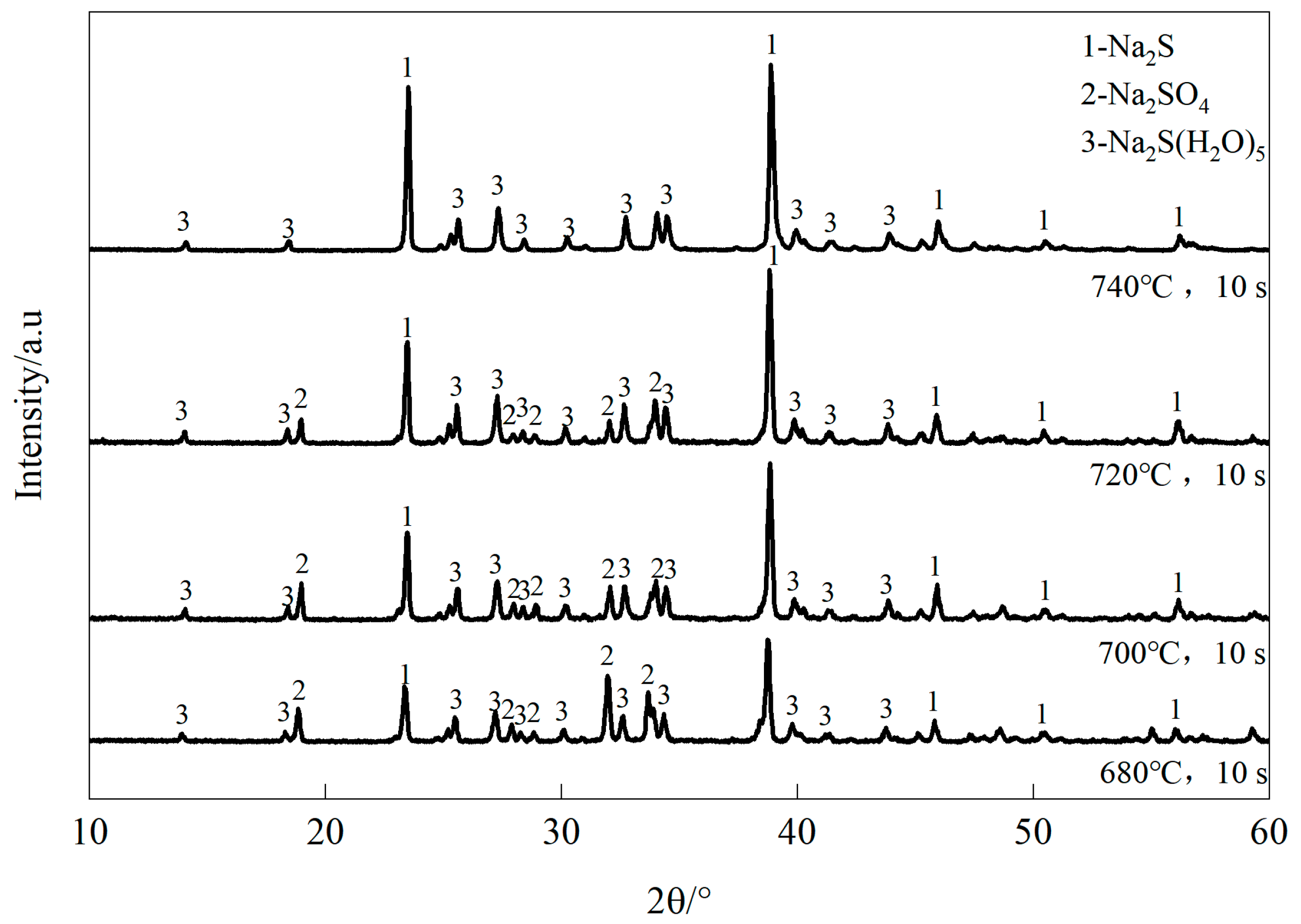
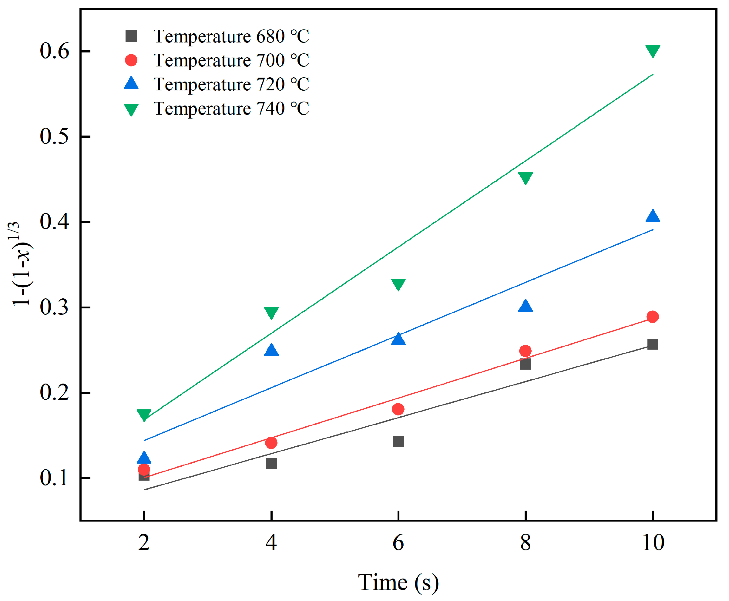
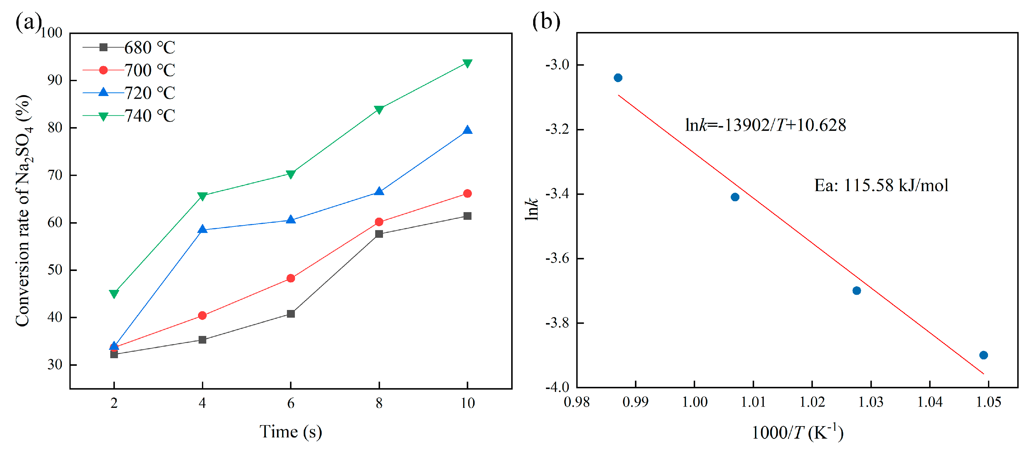
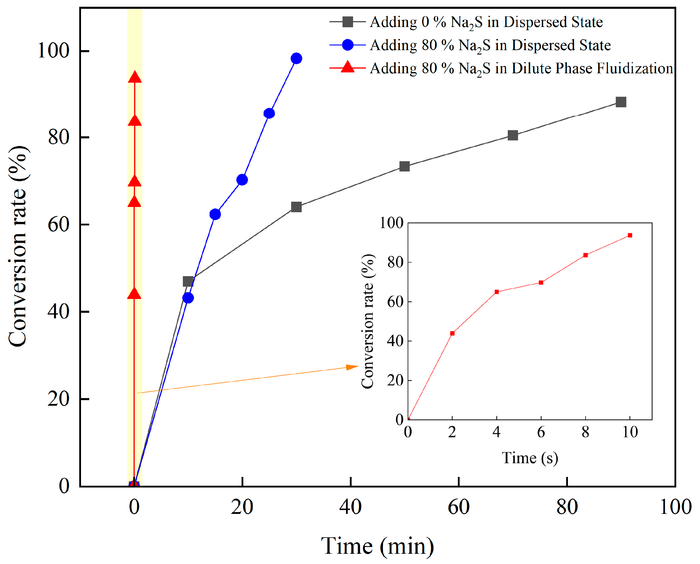
3.2. Characteristics of the H2 Reduction of Na2SO4 in a Mixed-Material System

Based on the experimental results of the eutectic characteristics, adding 80% Na2S to Na2SO4 increased the eutectic temperature of the binary system. Thus, this mixture was used as the reactant for the subsequent H2 reduction experiments at various temperatures; the results are presented in Table 3. Under the set reduction conditions, the reduction reaction of Na2SO4 occurred when the reaction temperature reached 680 °C. As the temperature or calcination time increased, the Na2SO4 content in the mixed-material system decreased, whereas the Na2S content increased. In dilute-phase fluidized systems, the residence time of the material is typically only a few seconds, which has significant advantages, such as a faster reaction speed and better gas-solid contact, over the traditional laboratory packed-state gas–solid reaction [14,15]. Moreover, the new process of Na2S external circulation could maintain a high proportion of Na2S in the reaction system, avoiding the reaction hindrance caused by the formation of a large amount of low-melting substances during the traditional gas reduction of Na2SO4.
Figure 2 shows the comparative XRD patterns of the reduction products after reduction at different temperatures. After reduction calcination at 740 °C for 10 s, the Na2SO4 content in the Na2S–Na2SO4 sample (Na2S:Na2SO4 ratio of 80:20) decreased to 1.26%, whereas the Na2S content increased to 98.74%. The peak height of the characteristic diffraction of Na2SO4 decreased with an increasing calcination temperature, whereas that of Na2S increased. After calcination at 740 °C for 10 s, the characteristic diffraction peak of Na2SO4 nearly disappeared, indicating that the reduction reaction of Na2SO4 was nearly complete at this point.
Two commonly used gas–solid reduction reaction models were employed in the parameter fitting to reveal the reduction mechanism [16,17,18,19,20,21]. The change in the conversion rate with the time at different reduction temperatures was analyzed using the interface chemical reaction and nucleation-growth models; the fitting parameters are presented in Table 4. The fitting results indicate that both models adequately described the Na2SO4 reduction. The interfacial chemical reaction model was used for the subsequent fitting, which was calculated as:
k t = 1 ( 1 x ) 1 / 3
G ( α ) = 0 t A exp ( E R T ) d t = k t
where, “k” refers to the reaction rate constant, “t” represents the time, “x” denotes the reduction rate, “G(α)” signifies the mechanism function, “A” is the pre-exponential factor, “E” stands for the activation energy, “R” represents the gas constant, and “T” indicates the absolute temperature.
According to Equations (2) and (3), plotting 1 − (1 − x)1/3 against t yields a straight line, as shown by the experimental data in Figure 3.
The kinetic equations calculated from the experimental data conformed to the actual results. The overall reaction rate increased with the temperature according to the Arrhenius law, which is an important characteristic of chemical reaction rate control. Thus, the model accurately described the process characteristics of the H2 reduction of Na2SO4 in the mixed-material system. A plot of lnk versus 1/T yielded the slope as −E/R and the y-axis intercept as lnA. The experimental results are plotted in Figure 4b to obtain the relationship between the temperature and the reaction rate constant (Equation (4)), as follows:
ln k = 13902 T + 10.628
The reduction kinetics of Na2SO4 at 680–740 °C are shown in Figure 4. The residence time of the material in the reactor is positively correlated with the reduction rate, as shown in Figure 4a. In a dilute-phase fluidized system, a material exists in a suspended state and is fully mixed with a reducing gas preheated to the reaction temperature [22]. By appropriately reducing the gas while ensuring the effective delivery of H2, the residence time of the material can be extended. An increase in the residence time promotes the reaction, thereby improving the reduction rate. This conclusion is consistent with thermodynamic principles, indicating that an increase in the temperature accelerates the reduction reaction of Na2SO4. Specifically, the experimental data confirmed a direct positive correlation between the temperature and reduction rate. The reaction progressed smoothly because the proportion of Na2S in the system was maintained above 80%, which is consistent with its eutectic characteristics. At higher temperatures, the absence or minimal presence of the liquid phase facilitated the reaction and maintained a rapid reaction rate. Figure 4b shows the plot of lnk against 1000/T. The apparent activation energy was calculated to be 115.58 kJ/mol, which lies between the typical reaction activation energies of 83 and 830 kJ/mol, indicating a kinetically fast reaction.
The H2 reduction reaction of Na2SO4 in the mixed-material system was simple. With the addition of 80% Na2S, the system consistently maintained an efficient gas–solid reaction with no or minimal liquid phase. H2 fully contacted the remaining 20% Na2SO4 in the system, and as the reaction time increased, it was gradually converted to Na2S, with the entire process being chemically controlled.
The reduction rates of Na2SO4 under different conditions are shown in Figure 5. The process of reducing pure Na2SO4 to Na2S was stable but slow in the dispersed state. Particularly, at 740 °C, a Na2SO4 conversion rate of 80% was achieved after approximately 90 min. In the gas–solid reaction process, the production costs are mainly affected by the consumption of the reducing gas; the demand for the reducing gas decreases as the conversion rate increases and the reaction time decreases, making it crucial to increase the reduction rate. According to the eutectic characteristics of the Na2SO4–Na2S system, the addition of a certain proportion of Na2S could increase the eutectic temperature. Therefore, samples containing 80% Na2S avoided or minimized the formation of a liquid phase even at 740 °C, thereby promoting full contact between H2 and Na2SO4 in the system and accelerating the reaction. The reduction rate of the sample containing 80% Na2S in the dispersed state was 1.5 times higher than that without added Na2S, which notably increased the reaction rate. Moreover, the sample with 80% Na2S achieved a conversion rate of 93.7% within 10 s under dilute-phase fluidization conditions, which greatly accelerated the reaction. This finding highlights the important role of dilute-phase fluidization in reducing the reaction time and accelerating the reaction process.
Figure 6 shows the elemental distribution map of the reduction product at 740 °C with the Na2S:Na2SO4 ratio of 80:20 and reaction time of 10 s. Figure 6a reveals the ellipsoidal particles with an approximate diameter of 50 μm obtained by calcining under an H2 atmosphere at 740 °C for 10 s. No notable agglomeration of the particles was observed, indicating that adding 80% Na2S to Na2SO4 as a reactant mixture promoted the dispersion between the product particles. The particles were primarily enriched with S and Na, with trace O elements distributed around larger particles, suggesting that the Na2SO4 in the mixture was nearly exhausted, as shown in Figure 6b–d, which is consistent with our chemical titration analysis and XRD results.
Figure 7 presents a comparative micrograph of the morphology of the pure Na2SO4 and the reduced Na2S of the sample with the Na2S:Na2SO4 ratio of 80:20 at 740 °C. As shown in Figure 7a,c, the product grains grew uniformly and exhibited isotropic characteristics. In contrast, Figure 7b,d show the considerable agglomeration and anisotropic characteristics of the product grains, which can be ascribed to the mediation of the liquid phase during the reaction process. The comparison revealed that adding 80% Na2S to the raw material inhibited the formation of a liquid phase, thereby enhancing the uniformity and homogeneity of the product. The micromorphology of the product not only reflects its physical and chemical properties but also affects its kinetic process. Generally, the activity and stability of the product increases and its reaction is promoted as the grain size decreases, the grain shape becomes more regular, the grain distribution becomes more uniform, the porosity decreases, and the specific surface area increases [23]. The addition of 80% Na2S to the raw material was beneficial for avoiding the formation of a liquid phase, thereby improving the uniformity and homogeneity of the product. Therefore, the optimal suspended state reaction conditions were determined as follows: calcination temperature of 740 °C, Na2S:Na2SO4 ratio of 80:20, and calcination time of 10 s. Under these conditions, the reduction reaction in the system with minimal liquid phase proceeded fully and effectively to prepare high-purity Na2S.

4. Conclusions

This paper proposes a novel environmentally friendly process for the reduction roasting of Na2SO4 to Na2S by dilute-phase fluidization. Experimental methods were carried out to determine the properties and performance of the system during the reduction reaction. The main conclusions obtained in this work are as follows:
  • The mixture of Na2S and Na2SO4 exhibited low-temperature eutectic characteristics. The system remained in a solid phase at temperatures below 700 °C. The eutectic temperature of the system increased with an increase in the proportion of Na2S at temperatures above 700 °C, reducing the generation of the liquid phase and alleviating fusion and clogging.
  • In the dilute-phase fluidization system, the samples with 80% Na2S and Na2SO4 as the reactant suppressed the formation of the liquid phase and accelerated the reduction process. After reduction roasting for 10 s, the characteristic diffraction peaks of Na2SO4 almost disappeared, indicating that the reduction was nearly complete. At this point, the Na2S content increased to 98.74%, achieving a high reduction rate of 93.7%.
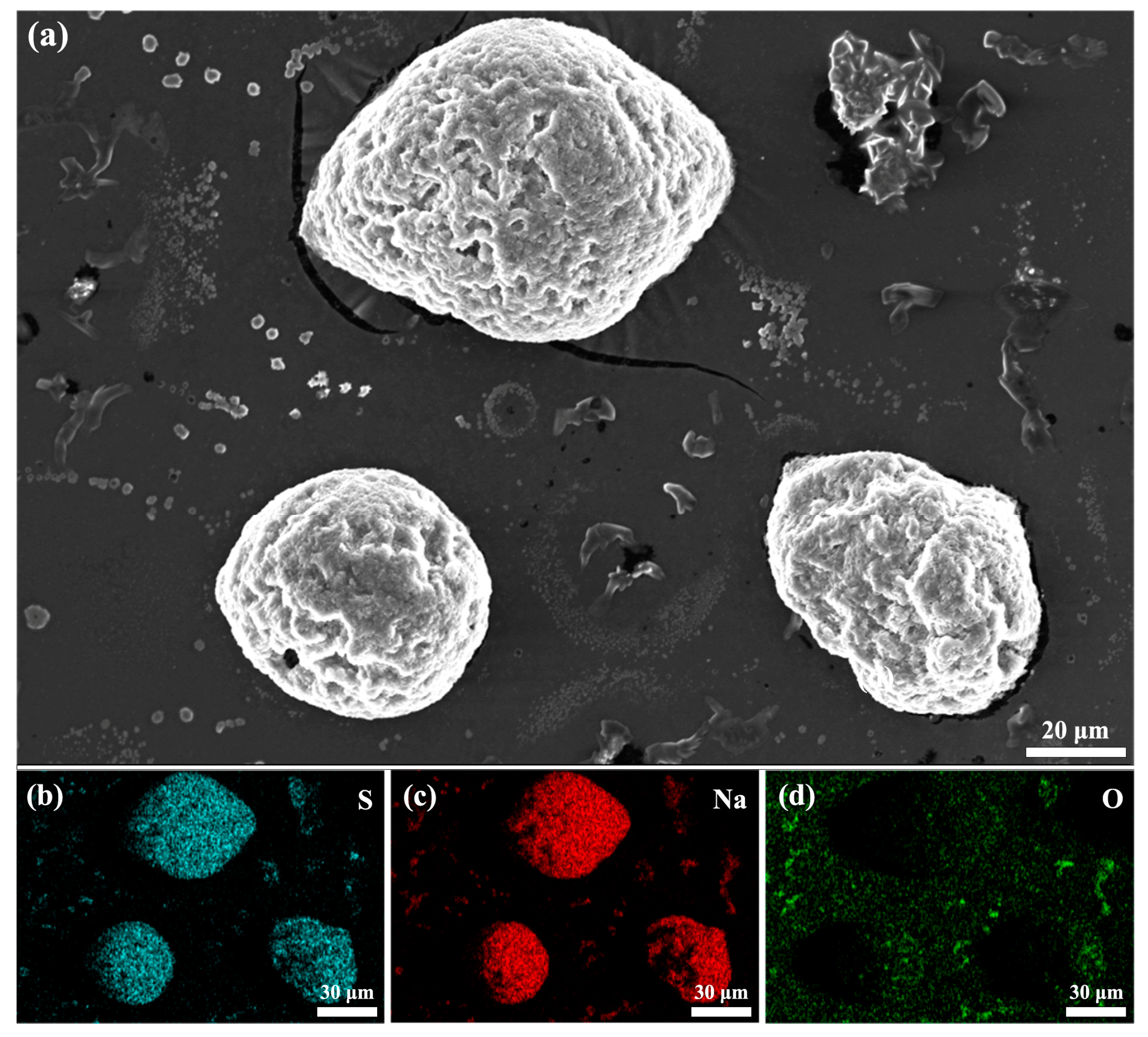
  • The microstructural morphologies of the products revealed their kinetic characteristics. The addition of 80% Na2S to the reactants accelerated the reduction rate and promoted the uniformity and homogeneity of the transformed products.

Author Contributions

Conceptualization, B.Z.; methodology, F.H.; validation, F.H.; formal analysis, S.H. and S.P.; investigation, F.H.; resources, B.Z.; data curation, F.H.; writing—original draft preparation, F.H.; writing—review and editing, C.C., B.Z. and Y.C.; supervision, B.Z. and Y.C.; project administration, Y.C. and B.Z.; funding acquisition, Y.C. and B.Z. All authors have read and agreed to the published version of the manuscript.

Funding

This research was supported by the Shaanxi Provincial Science and Technology Innovation Team (2021TD-53) and the Shaanxi Provincial Key Research and Development Program (2023GXLH-052).

Data Availability Statement

The data used to support the findings of this study are available from the corresponding author upon request.

Conflicts of Interest

The authors declare no conflicts of interest.

References

  1. Kostick, D.S. Sodium sulfate. In US Geological Survey Minerals Yearbook; U.S. Geological Survey (USGS): Reston, VA, USA, 2013; pp. 150–151. [Google Scholar]
  2. Du, Z.; Liu, F.; Liu, J.; Pan, F.; Fan, C.; Zhang, J. A green process for producing Na2S from waste Na2SO4 through hydrogen agglomerate fluidized bed reduction of baso4. J. Clean Prod. 2022, 355, 131816. [Google Scholar] [CrossRef]
  3. Smith, W.H.; Birnbaum, J.; Wolden, C.A. Production and purification of anhydrous sodium sulfide. J. Sulfur Chem. 2021, 42, 426–442. [Google Scholar] [CrossRef]
  4. Çelikler, C.; Varol, M. Investigation of control methods for agglomeration and slagging during combustion of olive cake in a bubbling fluidized bed combustor. J. Clean Prod. 2021, 320, 128841. [Google Scholar] [CrossRef]
  5. Hua, W.; Xu, X.; Zhang, X.; Yan, H.; Zhang, J. Progress in corrosion and anti-corrosion measures of phase change materials in thermal storage and management systems. J. Energy Storage 2022, 56, 105883. [Google Scholar] [CrossRef]
  6. Shen, X.; Shao, H.; Wang, Z.; Zhai, Y. Preparation of Na2S from Na2SO4 using co. Adv. Mater. Res. 2014, 1004, 706. [Google Scholar]
  7. Fu, H.; Chen, C.; Li, J.; Lan, Y.; Wang, L.; Yuan, J. Influence of na2s on the corrosion behavior of q345 steel in sodium aluminate solution. Mater. Res. Express 2019, 6, 1065a–1069a. [Google Scholar] [CrossRef]
  8. Pereira, R.J.L.; Hu, W.; Metcalfe, I.S. Impact of gas–solid reaction thermodynamics on the performance of a chemical looping ammonia synthesis process. Energy Fuels 2022, 36, 9757–9767. [Google Scholar] [CrossRef] [PubMed]
  9. Wang, E.; Hou, X.; Chen, Y.; Fang, Z.; Chen, J.; Liang, T.; Chou, K.; Nickel, K.G. Progress in cognition of gas-solid interface reaction for non-oxide ceramics at high temperature. Crit. Rev. Solid State Mat. Sci. 2021, 46, 218–250. [Google Scholar] [CrossRef]
  10. Zhang, X.; Li, X.; Weng, S.; Wu, S.; Liu, Q.; Cao, M.; Li, Y.; Wang, Z.; Zhu, L.; Xiao, R. Spontaneous gas–solid reaction on sulfide electrolytes for high-performance all-solid-state batteries. Energy Environ. Sci. 2023, 16, 1091–1099. [Google Scholar] [CrossRef]
  11. Osman, M.; Khan, M.N.; Zaabout, A.; Cloete, S.; Amini, S. Review of pressurized chemical looping processes for power generation and chemical production with integrated CO2 capture. Fuel Process. Technol. 2021, 214, 106684. [Google Scholar] [CrossRef]
  12. Simoncelli, M.; Marzari, N.; Mauri, F. Wigner formulation of thermal transport in solids. Phys. Rev. X 2022, 12, 41011. [Google Scholar] [CrossRef]
  13. Yang, Z.; He, Z.; Zhang, X.; Jiang, X.; Jin, Z.; Li, J.; Ma, L.; Wang, H.; Chang, Y. In-Situ gas flow separation between biochar and the heat carrier in a circulating fluidized bed reactor for biomass pyrolysis. Chem. Eng. J. 2023, 472, 145099. [Google Scholar] [CrossRef]
  14. Qie, Z.; Alhassawi, H.; Sun, F.; Gao, J.; Zhao, G.; Fan, X. Characteristics and applications of micro fluidized beds (mfbs). Chem. Eng. J. 2022, 428, 131330. [Google Scholar] [CrossRef]
  15. Di Renzo, A.; Scala, F.; Heinrich, S. Recent advances in fluidized bed hydrodynamics and transport phenomena—Progress and understanding. Processes 2021, 9, 639. [Google Scholar] [CrossRef]
  16. Leubner, I.H. Particle nucleation and growth models. Curr. Opin. Colloid Interface Sci. 2000, 5, 151–159. [Google Scholar] [CrossRef]
  17. Szabó, R.; Lente, G. General nucleation-growth type kinetic models of nanoparticle formation: Possibilities of finding analytical solutions. J. Math. Chem. 2021, 59, 1808–1821. [Google Scholar] [CrossRef]
  18. Ahn, B.; Bosetti, L.; Mazzotti, M. Secondary nucleation by interparticle energies. II. Kinetics. Cryst. Growth Des. 2021, 22, 74–86. [Google Scholar] [CrossRef] [PubMed]
  19. Wilkinson, C.J.; Cassar, D.R.; Deceanne, A.V.; Kirchner, K.A.; Mckenzie, M.E.; Zanotto, E.D.; Mauro, J.C. Energy landscape modeling of crystal nucleation. Acta Mater. 2021, 217, 117163. [Google Scholar] [CrossRef]
  20. Li, C.; Liu, Z.; Goonetilleke, E.C.; Huang, X. Temperature-dependent kinetic pathways of heterogeneous ice nucleation competing between classical and non-classical nucleation. Nat. Commun. 2021, 12, 4954. [Google Scholar] [CrossRef] [PubMed]
  21. Koga, N.; Vyazovkin, S.; Burnham, A.K.; Favergeon, L.; Muravyev, N.V.; Pérez-Maqueda, L.A.; Saggese, C.; Sánchez-Jiménez, P.E. Ictac kinetics committee recommendations for analysis of thermal decomposition kinetics. Thermochim. Acta 2023, 719, 179384. [Google Scholar] [CrossRef]
  22. Raganati, F.; Chirone, R.; Ammendola, P. Gas–solid fluidization of cohesive powders. Chem. Eng. Res. Des. 2018, 133, 347–387. [Google Scholar] [CrossRef]
  23. Geng, P.; Qin, G.; Zhou, J.; Li, T.; Ma, N. Characterization of microstructures and hot-compressive behavior of gh4169 superalloy by kinetics analysis and simulation. J. Mater. Process. Technol. 2021, 288, 116879. [Google Scholar] [CrossRef]
Figure 1. Schematic of the dilute-phase fluidized Na2SO4 reduction experimental apparatus.
Processes 12 00776 g001
Figure 2. Comparative XRD patterns of the reduction products after reduction at different temperatures.
Processes 12 00776 g002
Figure 3. Relationship between the kinetic mechanism function and time.
Processes 12 00776 g003
Figure 4. Reduction kinetics of Na2SO4 at 680–740 °C. (a) Conversion rate of Na2SO4 over time. (b) Calculation of the apparent activation energy.
Processes 12 00776 g004
Figure 5. Reduction rates of Na2SO4 under different conditions over time.
Processes 12 00776 g005
Figure 6. Elemental distribution of the reduced material at 740 °C with the Na2S:Na2SO4 ratio of 80:20. (a) SEM image; (b) Sulfur element distribution map; (c) Sodium element distribution map; (d) Oxygen element distribution map.
Processes 12 00776 g006
Figure 7. Morphology of Na2S–Na2SO4 mixture (80:20 ratio, respectively) (a,c) and pure Na2SO4 (b,d) reduced at 740 °C.
Processes 12 00776 g007
Table 1. Minimum fluidization velocities at various temperatures.
Material RatioAtmosphereT/°CViscosity/pa·sV0/m·s−1
Na2S:Na2SO4 = 8:2H26801.92 × 10−50.53
Na2S:Na2SO4 = 8:2H27001.93 × 10−50.52
Na2S:Na2SO4 = 8:2H27201.97 × 10−50.51
Na2S:Na2SO4 = 8:2H27401.99 × 10−50.51
Table 2. Melting points of Na2S–Na2SO4 mixtures at different temperatures.
SamplesInitial Mixing Ratio (wt%)Melt State during Roasting under N2 Flow for 30 min at Different Temperatures 1
Na2SNa2SO4680 °C700 °C720 °C740 °C760 °C
10100SSSSS
22080SSSSLL
33070SSLLL
44060SSLLL
55050SSLLL
66040SSLSLLL
77030SSSSLL
88020SSSSL
91000SSSSS
1 L indicates a liquid phase, S indicates a solid phase, SL indicates a solid–liquid phase.
Table 3. Properties after H2 reduction by Na2S–Na2SO4 mixtures at various temperatures.
T (°C)t (s)Raw Materials (wt%)Reduction Product (wt%)
Na2SO4Na2SNa2SNa2SO4
6802208085.6014.40
4208086.2513.75
6208087.4112.59
8208091.009.00
10208091.808.20
7002208085.9014.10
4208087.3312.67
6208089.0011.00
8208091.538.47
10208092.817.19
7202208086.4913.51
4208091.528.48
6208091.948.06
8208093.156.85
10208095.804.20
7402208088.7911.21
4208093.007.00
6208093.956.05
8208096.733.27
10208098.741.26
Table 4. Fitting parameters for the different reaction models.
T (°C) Nucleation   Growth   Model   ln ( 1 x )   =   ( k t ) m Interface   Chemical   Reaction   Model   k t   =   1 ( 1 x ) 1 / 3
k (min−1)mR2k (min−1)R2
6800.043050.621520.910040.021150.91646
7000.045360.565970.977410.023290.98301
7200.058450.471810.929810.030880.91831
7400.087150.481730.988670.050560.96535
Disclaimer/Publisher’s Note: The statements, opinions and data contained in all publications are solely those of the individual author(s) and contributor(s) and not of MDPI and/or the editor(s). MDPI and/or the editor(s) disclaim responsibility for any injury to people or property resulting from any ideas, methods, instructions or products referred to in the content.

