Abstract
During the operation of non-clogging pumps, the flexible long fiber is prone to clogging and winding during the flow process, which can result in damage to the non-clogging pump, so a numerical simulation method of a solid–liquid two-phase flow in a non-clogging pump with a flexible long fiber is proposed in this paper. The unsteady numerical simulation of the two-phase flow of a single flexible fiber with different densities, lengths and diameters in a double-blade non-clogging pump was carried out to study the influence of fiber parameters on fiber transport capability. The results show that at a density of 920 kg/m3, 300 kg/m3 and 732 kg/m3, the transport capability of flexible fibers decreases successively, and the transport time T0 is 0.32 s, 0.36 s and 0.48 s, respectively. The transport capability of flexible fibers with a length of 150 mm, 200 mm and 250 mm decreases successively, and the transport time T0 is 0.34 s, 0.48 s and 0.96 s, respectively. The transport time T0 is 0.48 s when the fiber diameter dp is 5 mm. When the fiber diameter dp is 7.5 mm, the transport time T0 is 0.51 s. When the fiber diameter dp is 10 mm, the fiber transport capability of the non-clogging pump decreased significantly, and the transport time T0 is 0.68 s. The fiber length has the most obvious effect on fiber transport capability, followed by the fiber diameter and fiber density.
1. Introduction
As a kind of fluid machinery, the pump has a wide range of applications in modern industry and is one of the core pieces of equipment for industrial fluid transportation. According to the different structural forms of pumps, non-clogging pumps can be divided into submersible, vertical and horizontal pumps. The key to its non-clogging performance lies in the structural type of the impeller. At present, the main structural types of non-clogging pump impellers are as follows: closed impeller, open or semi-open impeller, swirl impeller, spiral centrifugal impeller and runner impeller. Different types of impellers also have different characteristics. Considering the aspects of anti-winding, anti-clogging, conveying capacity, efficiency, manufacturability, economy, reliability and advancement, the double-channel pump is the main impeller structure type used in the current high-efficiency non-clogging pump. However, the efficiency of flow-channel non-clogging pumps is still lower than that of vane centrifugal pumps; their research is relatively scarce, and they are far less in-depth and extensive than vane pumps. Therefore, it is of great significance for the research of vane-free pumps.
In the study of solid–liquid two-phase flow within pumps, a prominent concern is the tendency of solid particles, fibers and other particulate matter to cause blockages during transport. This leads to issues such as reduced pump head, poor efficiency, shorter lifespan and decreased seal reliability. Numerous researchers have conducted extensive studies on solid–liquid two-phase flow pumps through simulations and experiments. Walker et al. [1] investigated the effects of flow rate and particle size on the wear of slurry pumps through experiments. The results indicated that at 80% of the rated flow rate, the wear on the pump caused by particles was minimal. When the particle size is coarse, the impeller wear is more severe, while finer particle sizes lead to more pronounced wear at the volute throat. Li et al. [2,3] studied the impact of the particle diameter and concentration on pump efficiency through experiments. They found that as the particle diameter and volume fraction increase, the pump’s peak efficiency decreases and gradually deviates towards lower flow rate conditions. Liu et al. [4] conducted particle image velocimetry (PIV) experiments to study the solid–liquid two-phase flow inside chemical pumps. The research showed that compared to water-only conditions, solid particles reduce the outflow velocity of the liquid phase. Tarodiya et al. [5] investigated the effects of particle size and concentration on the performance of slurry pumps. The results indicated that with an increase in particle concentration and particle size, both the pump head and efficiency decrease. Charoenngam [6] used PIV experiments to study the velocity and kinetic energy fluctuations of particles at the tongue position of centrifugal pumps. The study revealed that when the impeller speed increases from 750 rpm to 1000 rpm, the fluctuating kinetic energy of the particles increases by two to five times.
Long fibers are prone to agglomeration and entanglement during the conveying process, which can cause pump blockage and reduced efficiency, and in severe cases, it can result in entangled pump shafts and burned motors. However, the current research on non-clogging pumps for solid–liquid two-phase flow mostly focuses on the conveying of rigid small particle solid–liquid mixtures and the suspension of fine fibers. There are still many technical bottlenecks and challenges in handling media containing flexible long fibers. Therefore, conducting research on the solid–liquid two-phase flow inside non-clogging pumps with flexible long fibers is crucial for improving the performance of non-clogging pumps and achieving more efficient media conveying.
The CFD-DEM coupled simulation is a widely used method for multiphase flow numerical modeling. It replaces the solid particle flow in the two-phase flow with dispersed particle units and considers the interaction between the fluid phase and the particle phase. Huang [7] used the CFD-DEM method to study the unsteady solid–liquid two-phase flow in the centrifugal pump and explored the motion law of the solid particle population and its influence on the characteristics outside the pump. Chaumeil et al. [8] simulated Brownian particles using CFD-DEM, obtained the settling of particles in pipelines and validated the authenticity of the coupled simulation through experiments. Azimian et al. [9] used the CFD-DEM coupling method to calculate the particle wear in pipeline flows and verified the high reliability of the coupled simulation through experimental data. Jiang [10] established a mathematical model of the coupling between particle and liquid phases based on the CFD-DEM coupling method and determined that the CFD-DEM coupling method is suitable for the simulation of the movement law of sand particles in oil–water pipelines through the simulation calculation of solid–liquid two-phase flow. Tang [11] used the CFD-DEM method to simulate the flow of salting-out liquid–solid two-phase flow in a centrifugal pump and accurately predicted the aggregation, collision and crushing of particles in the salting-out process in the centrifugal pump. Salikov et al. [12] simulated a prismatic spouted bed using CFD-DEM and obtained particle motion characteristics, which are similar with experiments. Sun et al. [13] analyzed the collision characteristics and velocity distribution of solid particles in the solid–liquid two-phase flow in a pump using the CFD-DEM coupling method.
In a numerical simulation of solid–liquid two-phase flow containing fibers, the deformation and orientation of fibers are complex. In 1922, Jerrery [14] first studied the motion of ellipsoidal particles in simple shear flows and proposed the Jerrery equation, which can be used as a theoretical basis for simulating the motion of axisymmetric rigid fiber particles. In 1988, Fu et al. [15] proposed a rigid spherical fiber model and found that at low concentrations, the forces acting on fibers in flow, such as the physical force R, fluid drag force P and rotational lift force F, are directly related to the size of the outer surface area occupied by the dispersed fibers in the suspension. Zhang et al. [16] used the CFD-DEM method to simulate the flow of fiber particle suspensions in a centrifugal pump and validated it with PIV experiments, but the fiber model used was still a rigid fiber model. In 1993, Yamamoto et al. [17] first introduced the flexible fiber model, which can simulate the stretching, bending and twisting deformations of fibers in fluid by changing the connecting distance, bending angle and torsion angle between adjacent spheres. Based on this, various flexible fiber models, such as spherical chain fiber model, ellipsoidal chain fiber model and cylindrical rod chain fiber model have been proposed by many researchers [18,19,20]. Zhang et al. [21] improved the cylindrical rod chain fiber model proposed by Schmid et al. and introduced a new cylindrical rod chain fiber model with semicircular ends on both sides. Geng et al. [22] used a slender chain structure for numerical simulation and analyzed the distribution characteristics of slender flexible particles in a fluidized bed. Nan et al. [23] modeled flexible fibers in a simple shear flow field based on the rod chain model and validated the model using the numerical simulation of fibers with relatively large effective stiffness. Yang et al. [24] developed a numerical model with surface-smooth and flexible fiber particles based on the discrete element method and simulated the stretching, bending and twisting of a single fiber particle under cantilever beam constraints. Jiang et al. [25] used the CFD-DEM coupling method to achieve a numerical simulation of flexible fiber particle gas–solid fluidized beds and obtained important characteristic information about the fluidization effect. Kang et al. [26] used the Fluent-EDEM bidirectional coupling method to simulate the flow process of flexible fiber suspensions in a pump and studied the flow field and motion characteristics of fibers.
In summary, the research on the motion characteristics of flexible fibers in non-clogging pumps is still insufficient, especially in the study of solid–liquid two-phase flow with flexible long fibers. Therefore, this paper proposes a numerical simulation method for solid–liquid two-phase flow with long fibers in non-clogging pumps and conducts unsteady numerical simulations of the two-phase flow inside a double-blade non-clogging pump with different densities, lengths and diameters of single flexible fibers. The focus is on the influence of parameters of single long fibers on the fiber passage performance.
2. Numerical Simulation Method of Solid–Liquid Two-Phase Flow with Flexible Fiber
2.1. CFD-DEM Bidirectional Coupling Model
The flexible fiber model adopted the cylindrical rod chain flexible fiber model. Figure 1 shows the flexible fiber model of a cylindrical rod chain. The cylindrical rod chain fiber model considers a single fiber as a rod chain formed by m rigid cylindrical rods connected by ball hinges, where the rigid cylindrical rod is referred to as the fiber element. Both ends of the cylindrical rod are semicircular, and the cylindrical rods are connected by ball hinges. The center distance of the two semicircular ends of each fiber element is l, and the diameter of the circle is dp. The aspect ratio of each fiber element rps is l/dp. The total length of the fiber L is ml, and the aspect ratio of the fiber rp is L/dp.

Figure 1.
Cylindrical rod chain fiber model: (a) fiber model; (b) fiber element model.
According to Newton’s Second Law and the conservation of angular momentum, for any fiber element i, the following is calculated:
wherein mi is the mass of the fiber element, vi is the translational velocity of the fiber element, Fi is the resultant external force on the fiber element, Ii is the rotational inertia of the fiber element, ωi is the angular velocity of the fiber element and Mi is the resultant torque on the fiber element.
Compared to general solid particles, in the equation of the translational motion of fiber elements, in addition to the hydrodynamic force Ffi exerted by the fluid on the fiber element, the mechanical contact force Fci caused by the contact between the fiber elements and the wall and the gravity suffered by the fiber element, it is necessary to consider the constraint force Xi at each ball hinge joint. Similarly, the moment exerted on the fiber element includes the hydrodynamic moment Mfi caused by the liquid phase, the moment Mci caused by mechanical contact, the restraining force moment and the restoring moment Yi at each ball hinge joint. The motion equation of the fiber element can be obtained by introducing the above equation as follows:
wherein Xi is the constraint force exerted on the fiber element at ball hinge joint i, l is the length of the fiber element, pi is the direction vector of the fiber element and Yi is the restoration moment of the fiber element at ball hinge joint i.
To analyze the drag force on fibers in the flow field, the drag force model proposed by Marheineke and Wegener [27] for fibers in turbulent flow was employed. According to the independence principle of static flow around a cylinder, the expression for the drag force per unit length on an infinite cylinder can be derived as follows:
wherein ρf is the fluid density, dp is the fiber diameter, is the unit vector in the normal direction, is the tangential unit vector parallel to the axis of the spherical cylinder, and are the normal and tangential components of the velocity of the fluid relative to the spherical cylinder fiber element, CD,n is the normal drag coefficient and CD,τ is the tangential drag coefficient.
The calculation formula for the Reynolds number, Ren, of the normal component of the fluid velocity relative to the spherical cylindrical fiber element is as follows:
wherein μf is the liquid phase dynamic viscosity coefficient.
The coefficient rD,γ is defined as the product of the drag coefficient and Ren:
The expression for the drag per unit length on an infinite cylinder can be simplified as follows:
wherein rD,n is the product of the normal drag coefficient and Ren and rD,τ is the product of the tangential drag coefficient and Ren.
According to the drag model of fibers in turbulence proposed by Marheineke and Wegener, it can be inferred that when Ren > 100, the expression is as follows:
In the modeling of flexible long fibers, the equations of motion (3) and (4) of the fiber elements are compiled into the numerical simulation application of discrete terms, and in the CFD-DEM two-way coupling calculation, the parameters of the adaptation are filled in according to the drag model of the fiber in turbulence proposed by Marheineke and Wegener.
2.2. CFD-DEM Bidirectional Coupling Calculation
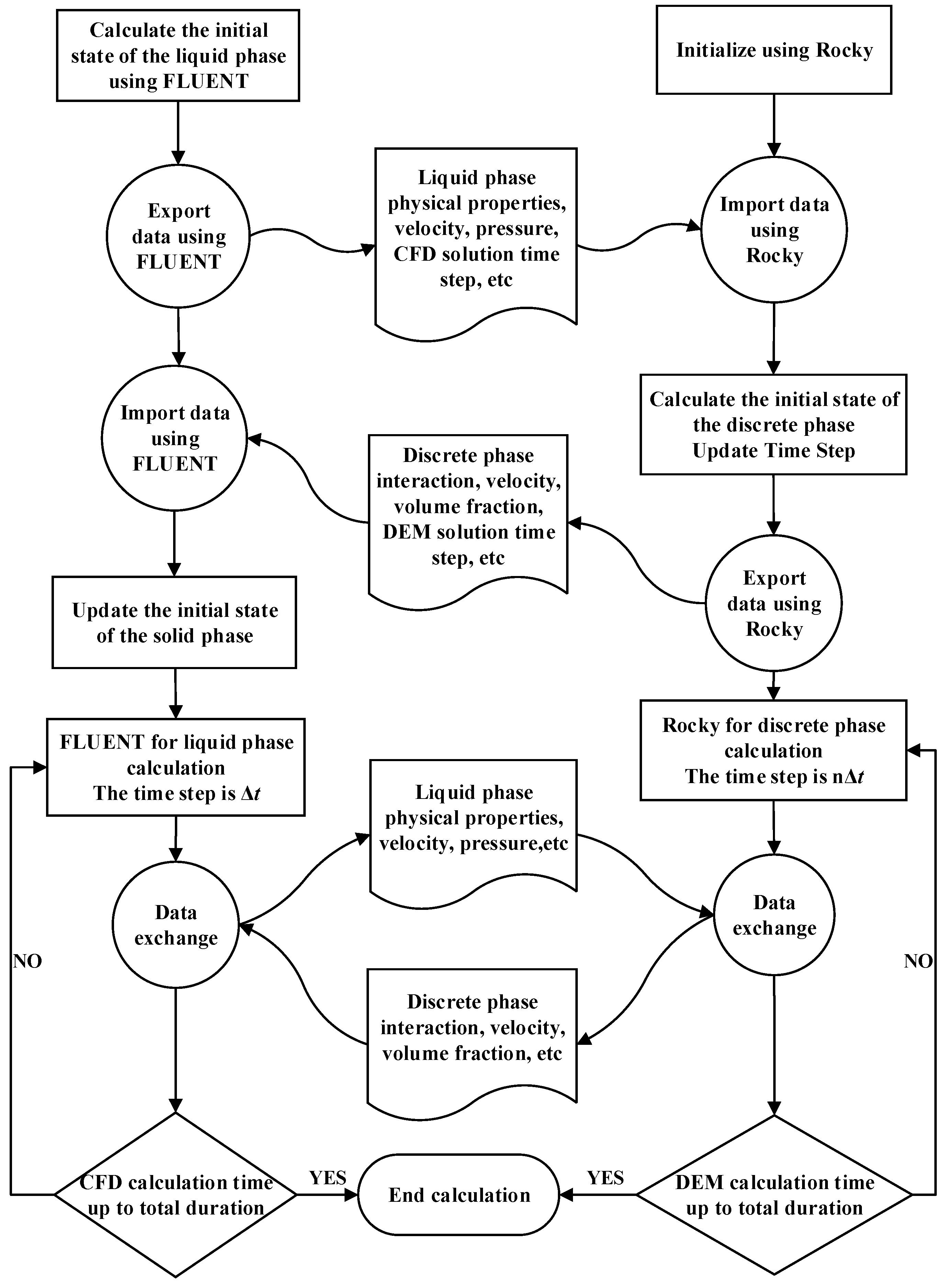
This paper adopted the bidirectional transient coupling method of CFD-DEM, applying CFD (computational fluid dynamics) and DEM (discrete element method) to numerically simulate the liquid phase (continuous phase) and solid phase (discrete phase), respectively. The dynamic information calculated from both methods was coupled to achieve the transfer of mass, energy and momentum between the continuous phase and discrete phase. This method allowed for the separate calculation of the liquid phase and solid phase based on their respective characteristics while ensuring effective information exchange between each other. Therefore, it can describe the motion state of the solid–liquid two-phase flow field in the pump. The CFD tool used in this study was Fluent, and the DEM tool was Rocky. The coupling simulation process of CFD-DEM is shown in Figure 2.
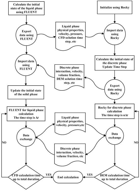
Figure 2.
Coupling simulation process of CFD-DEM.
2.3. Validation of CFD-DEM Bidirectional Coupling Model
In reference [26], the relative velocities within the impeller channels of a centrifugal pulp pump were measured using a PIV system while transporting fiber suspensions of different concentrations at various flow rates. To validate the CFD-DEM bidirectional coupling model and the flexible fiber model, numerical calculations were performed on a centrifugal pulp pump with flexible fiber suspensions. The relative velocities within the impeller channels were analyzed and compared with the experimental results mentioned in the reference [26].
In reference [26], an open three-blade centrifugal pulp pump was provided. Its flow rate Qd is 33.5 m3/h, head Hd is 8.5 m and rotational speed n is 1450 r/min. The software ICEM 2020 R2 was used for grid generation and grid independence verification of the water domain in the centrifugal pulp pump. The final grid scheme consisted of a total of 2.17 million.
The liquid phase calculation used FLUENT for pre-processing settings, with reference pressure set to standard atmospheric pressure, which was 101,325 Pa, and gravitational acceleration set to 9.81 m/s2 in the negative y-axis direction, which was opposite to the flow direction of the pump outlet. The rotational speed of the impeller domain was set to 1450 r/min. The inlet boundary condition was set as a mass flow inlet with a flow rate of 9.287 kg/s, and the inlet turbulence intensity was set to 5%. The outlet boundary condition was set as a free outflow, while the wall boundary condition was set to the standard wall function. The chosen turbulence model was the standard k-ε model. The time step was set to 0.00069 s, with 20 iterations per step. The convergence criterion was set to 10−3. The total number of steps was set to 1000, resulting in a total calculation time of 0.69 s.
In reference [26], the flexible fiber material used in the PIV experiment is made of polypropylene, with the density ranging from 0.90 to 0.92 g/cm3. The experiment used polypropylene monofilaments with a length of 3 mm and a diameter of 30 μm. In order to replicate the polypropylene monofilament, a flexible fiber model with a length L of 3 mm and a diameter dp of 0.03 mm is established. This model consists of 100 rigid fiber elements of equal length, where the length l of each fiber element is 0.03 mm. The ends of the fiber elements are hemispherical, and the cylindrical rods are connected with spherical hinge joints. Each fiber element has the length-to-diameter ratio rps of 1, and the length-to-diameter ratio of the fiber rp is 100. The fiber model is set up using multiple elements, treating each fiber element as an individual element, resulting in each fiber being composed of 100 elements. The Marheineke and Wegener drag model is used. The fiber material selected is polypropylene, with a density ρ of 900 kg/m3 and Young’s modulus of 1.35 × 10¹⁰ N/m2.
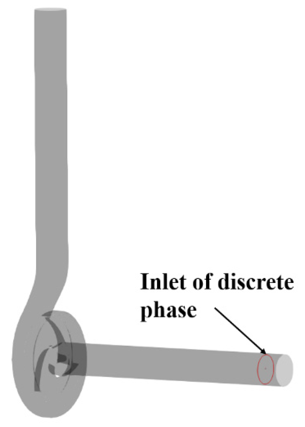
The water body of the centrifugal pulp pump was separated into wall faces and imported into Rocky. According to the cited wall material properties, the wall material density was set to 1200 kg/m3 and Young’s modulus to 9.37 × 10⁹ N/m2. The impeller wall rotation speed was set to 1450 r/min. A discrete phase material inlet was established at the entrance of the extended section of the centrifugal pulp pump inlet; the mass flow rate of the discrete phase inlet was set, changing the mass concentration of the fiber suspension. The wall and discrete phase inlet of the centrifugal pump is shown in Figure 3.
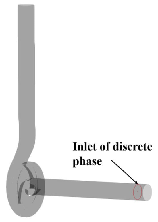
Figure 3.
Wall and discrete phase inlet of the centrifugal pump.
The 2-Way CFD Coupling was set up in Rocky, the case file of the saved liquid phase calculation was imported into Rocky and the calculation time step nΔt of 0.00345 s of the discrete phase was set, where n was 5 and the total duration was the same as the liquid phase calculation.
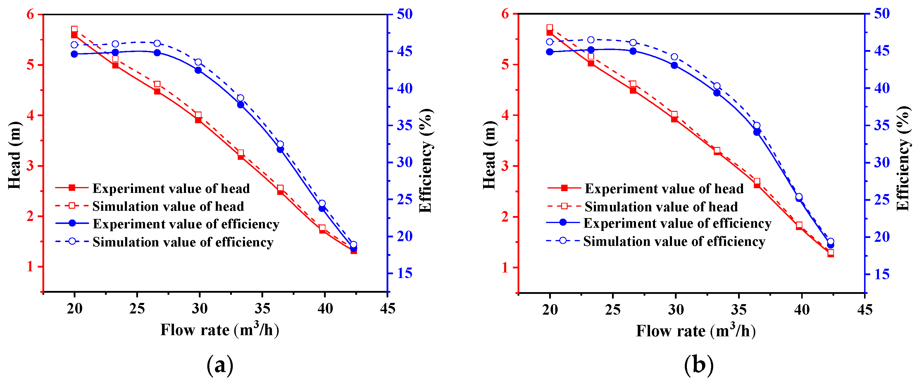
In reference [26], external characteristic experiments were conducted at room temperature when centrifugal pulp pumps were used to transport clear water and fiber suspensions of different concentrations. The experiments provided the head and efficiency of the pump for different flow rates when transporting clear water, 0.3%, 0.5% and 0.7% mass concentrations of fiber suspensions. In this section, the external characteristics of the centrifugal pulp pump were calculated using the CFD-DEM coupling method for the transportation of clear water and 0.3% mass concentration fiber suspension and compared with the experimental values. The comparison with simulation values and experiment values is shown in Figure 4. The calculated results of the external characteristics of different flow rates during the transportation of clean water were consistent with the experimental results, with a maximum error of 3.66% in the head and 2.90% in efficiency. The calculation results of the external characteristics of different flow rates during the transportation of the fiber suspension with a mass concentration of 0.3% were consistent with the experimental results, with a maximum error of 3.02% in the head and a maximum error of 3.00% in efficiency. Within a wide range of operating conditions, the head and efficiency of the centrifugal pulp pump when transporting a 0.3% mass concentration fiber suspension were both higher than when transporting clear water. This is consistent with the experimental results in the literature and verifies the CFD-DEM coupling model established in this paper.
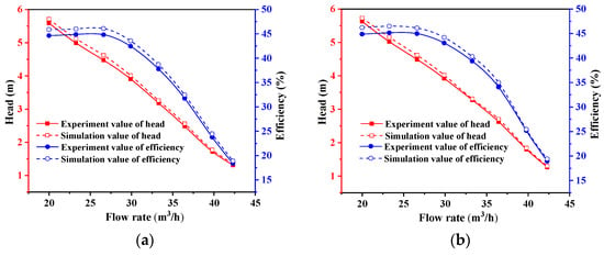
Figure 4.
Comparison with simulation values and experiment values: (a) clear water; (b) mass concentration of 0.3%.
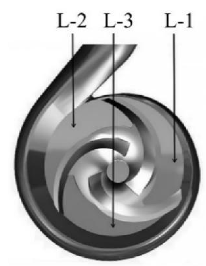
In reference [26], PIV experiments were conducted to collect the relative velocity distribution within different impeller flow channels when transporting clear water and fiber suspensions of different mass concentrations under rated conditions. The variable r0 was the current position radius size, r2 was the impeller outlet radius size and r0/r2 was the relative radius. The impeller passage of the pump is shown in Figure 5.
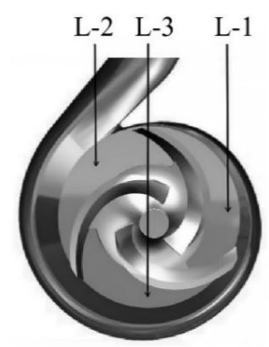
Figure 5.
Impeller passage of the pump.
During the PIV acquisition process, the reflection and refraction of the laser caused by the contour and blades of the pulp pump led to a more uniform distribution of the laser within the L-2 channel compared to other channels, resulting in smaller relative errors. Therefore, the literature focused on analyzing the relative velocity distribution specifically within the L-2 channel.
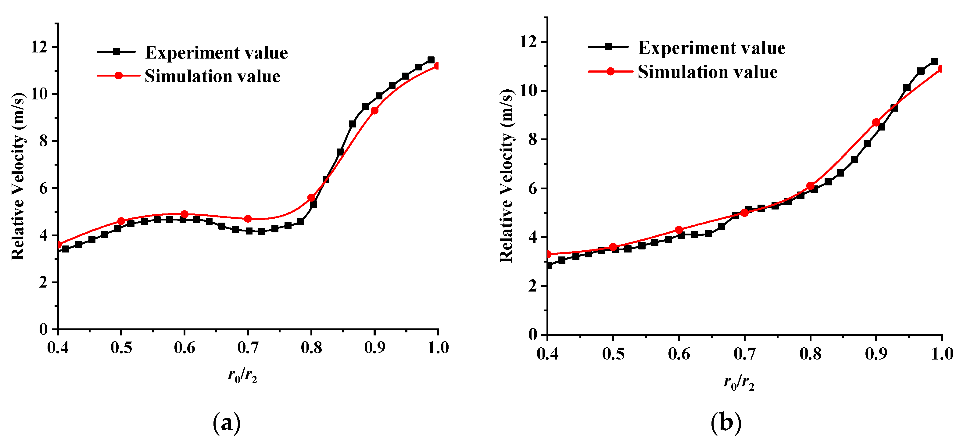
Through the coupling method of CFD-DEM, numerical simulations were carried out for the transport of a fiber suspension with a mass concentration of 0.3% through a centrifugal pulp pump. The relative velocities at different positions within the flow channel were extracted for comparison with experimental values. Figure 6 illustrates the relative velocity distribution at a fiber suspension of 0.3% under design flow rate. It can be observed from the figure that when a fiber suspension with a mass concentration of 0.3% is transported under rated flow rate, the trend of the relative velocity distribution near the pressure surface and suction surface of the blade obtained from the numerical simulation is consistent with the experimental values. The maximum error of relative velocity distribution near the suction surface was 5.21%, and the maximum error of relative velocity distribution near the pressure surface was 6.15%. This further verified the accuracy of the CFD-DEM coupling model established in this paper.
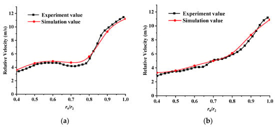
Figure 6.
The relative velocity distribution at a fiber suspension of 0.3% under design flow rate: (a) suction surface; (b) pressure surface.
3. Simulation Model and Research Plan
3.1. Simulation Model
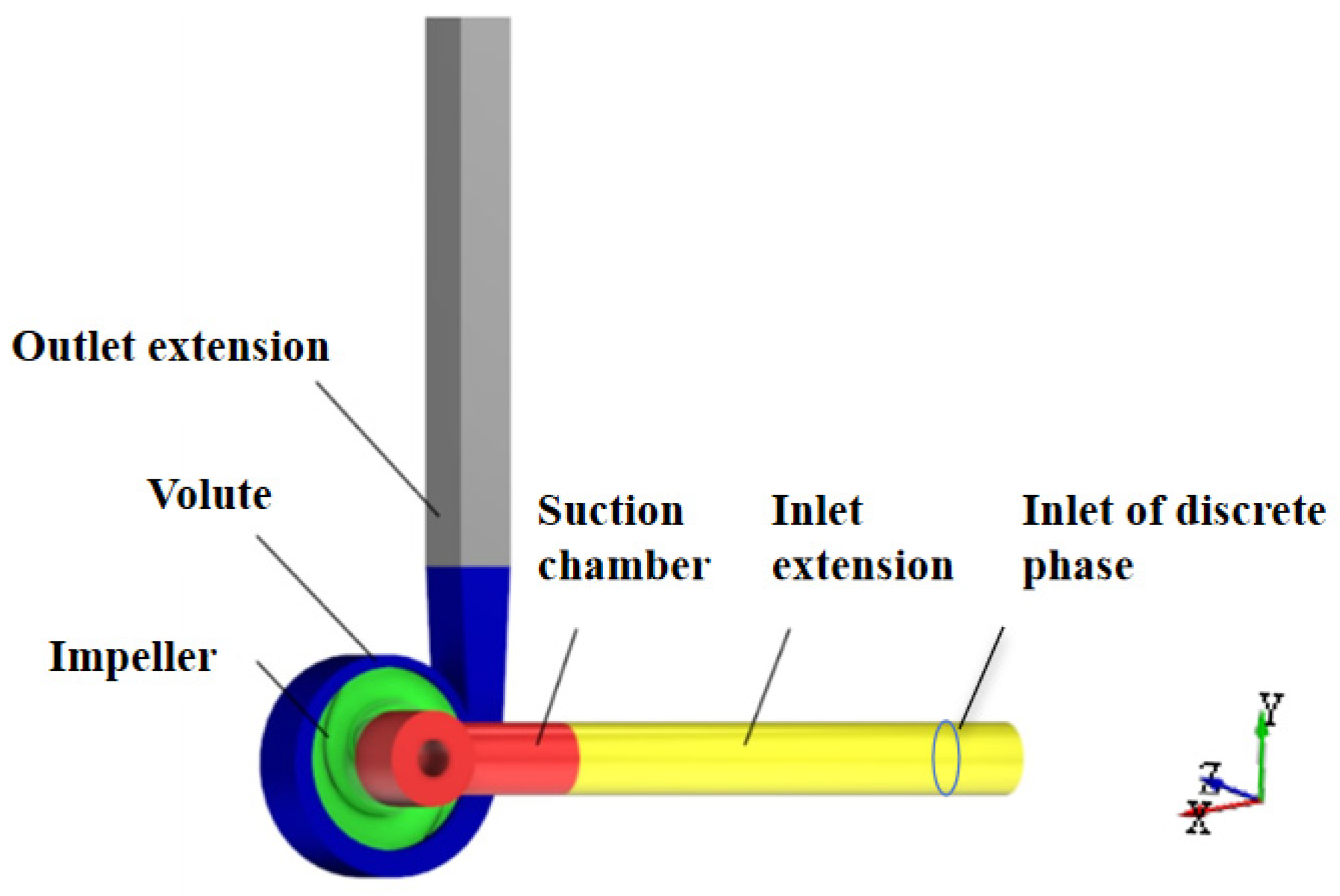
The research object was a double-blade non-clogging pump, whose design flow rate Qd was 25.86 m3/h, head Hd was 3.45 m and rotation speed n was 750 r/min. The main structural parameters of the double-blade pump are shown in Table 1. The simulation model of the double-blade non-clogging pump included a suction chamber, open impeller, volute, inlet extension section and outlet extension section, as shown in Figure 7.

Table 1.
Main structural parameters of the double-blade pump.
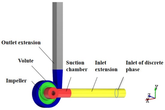
Figure 7.
Simulation model of the double-blade pump.
A tetrahedral mesh was used to partition the calculation domain of the non-clogging pump, and the grids for the blades and interface were refined. Four different grid partitioning schemes with varying numbers of grids were implemented, and the grid quality for each part was above 0.3. The pump head for different grid schemes of the double-blade non-clogging pump under rated operating conditions was calculated using FLUENT 2020 R2 software to perform grid independence check. The grid independence check is shown in Table 2.

Table 2.
Grid independence check.
According to Table 2, when the number of grids was 4.94 million and 5.52 million, the calculated values of the head were 3.464 m and 3.478 m, respectively, with a relative deviation of 0.40% between the two schemes. In order to save computational resources and improve computational efficiency, Scheme 3 was selected for numerical simulation. The number of grids was 4.93 million, and the maximum size of the impeller grid was 3 mm. The maximum size of the grid for the volute, suction chamber and inlet and outlet extension section was 4 mm. The grid was encrypted for the blades, volute tongue and interfaces.
3.2. Calculation Settings
The liquid phase calculation used FLUENT for pre-processing settings, with a reference pressure set to standard atmospheric pressure, which was 101,325 Pa, and a gravitational acceleration set to 9.81 m/s2 in the direction opposite to the pump outlet. The inlet boundary condition was set as a mass flow rate inlet with specific values adjusted based on actual operating conditions. The outlet boundary condition was set as a free outflow, while the wall boundary condition was set to the standard wall function. The time step was set to calculate one step per 6° of impeller rotation, for which Δt was 0.00133 s. Each step iterated 20 times with a convergence criterion of 10−3.
The water body of the double-blade non-clogging pump was separated into wall faces and imported into Rocky. The wall material was steel, and the density was 7850 kg/m3, with a Young’s modulus of 1 × 10¹¹ N/m2; the impeller wall rotation speed was set to 750 r/min. A discrete phase material inlet was established at the inlet extension of the double-blade non-clogging pump, and the mass flow rate was set at the discrete phase inlet to ensure the flow of a single fiber in the double-blade pump. Flexible fiber model schemes were established with different lengths, diameters and densities, as shown in Table 3.

Table 3.
Schemes of flexible fiber model.
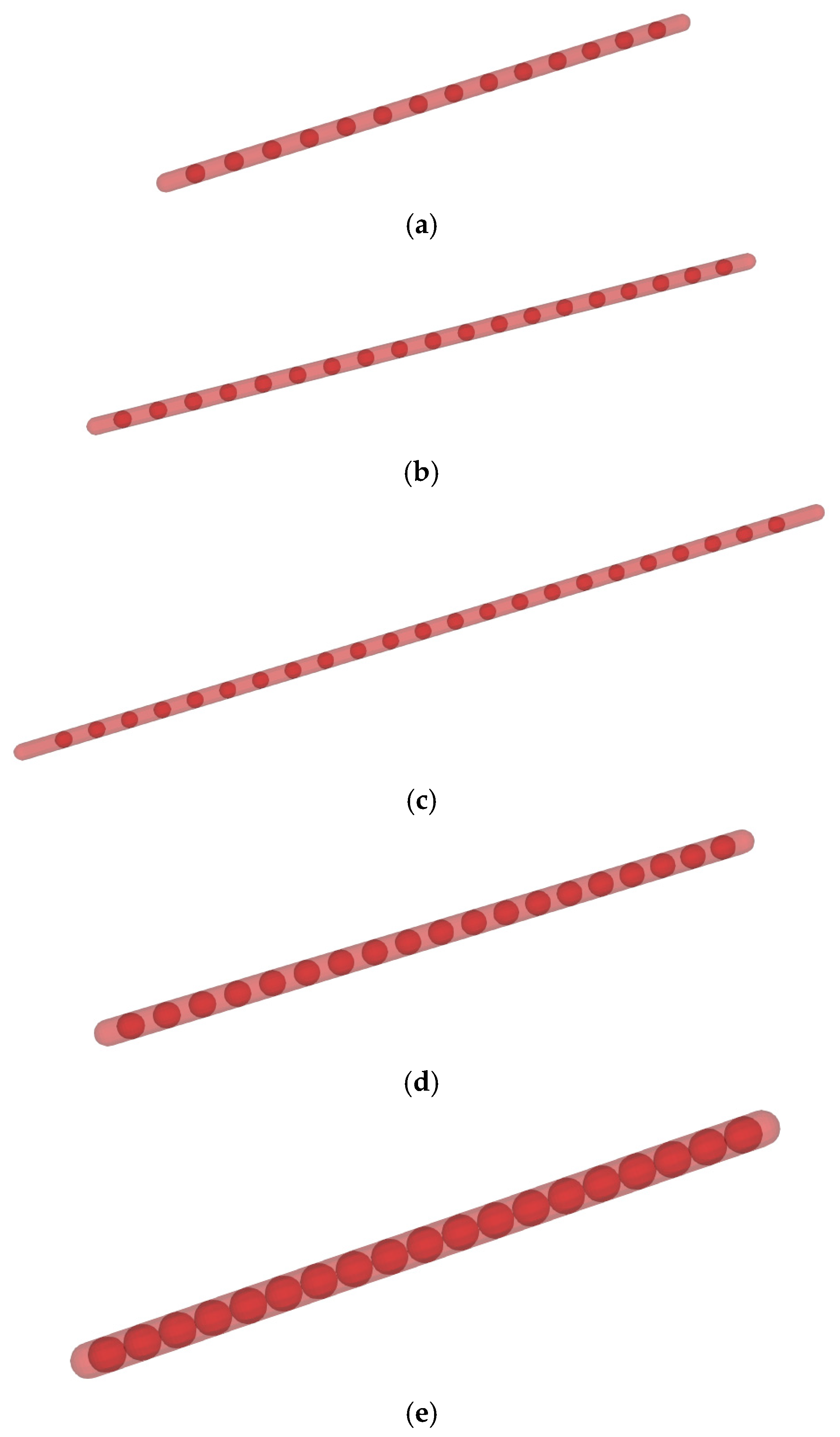
The flexible fiber was composed of fiber units with different quantities and diameters. The length of each fiber unit l was 10 mm, and the two ends of the fiber unit were semi-circular spherical. The cylindrical rods were connected by ball joints. The fiber length L was controlled by changing the number of connecting fiber units, with values of 150 mm, 200 mm and 250 mm. The fiber diameter dp was controlled by changing the diameter of the fiber units, with values of 5 mm, 10 mm and 15 mm. Different density schemes of the fiber were achieved using different materials—cotton fiber with a density of 300 kg/m3, hay fiber with a density of 732 kg/m3 and polypropylene fiber with a density of 920 kg/m3. Fiber models with different lengths and diameters are shown in Figure 8.
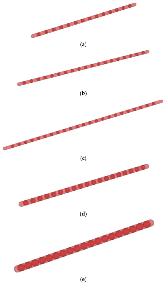
Figure 8.
Fiber models with different lengths and diameters. (a) L = 150 mm, dp = 5 mm; (b) L = 200 mm, dp = 5 mm; (c) L = 250 mm, dp = 5 mm; (d) L = 200 mm, dp = 7.5 mm; (e) L = 200 mm, dp = 10 mm.
Due to a number of external factors, the timing of each fiber entering the pump was uncertain, so the time it took for the fiber to pass through the double-blade non-clogging pump was slightly different. In order to be able to fully and correctly compare the effects of different characteristics of the fiber on the passage of the non-clogging pump, we performed 10 repeated numerical simulation calculations for each fiber model and counted the time of each simulation to calculate the fiber passing through the non-clogging pump, and we took the closest calculation result to the truth for analysis.
The fiber model was configured using multiple elements, where each fiber unit was considered a single element. The fibers with the lengths L of 150 mm, 200 mm and 250 mm were composed of 15, 20 and 25 elements, respectively. Different fiber density schemes were set accordingly. The Marheineke and Wegener drag model was applied. The calculation time step of the discrete phase is set at nΔt of 0.00665 s, which n is 5, with the total duration being the same as the fluid phase calculation. To ensure fiber outflow, the total duration is set to the time for the impeller to rotate ten times, for which T is 0.8 s.
4. Results and Analysis
4.1. Flow Characteristic Analysis of Fibers with Different Densities in a Double-Blade Non-Clogging Pump
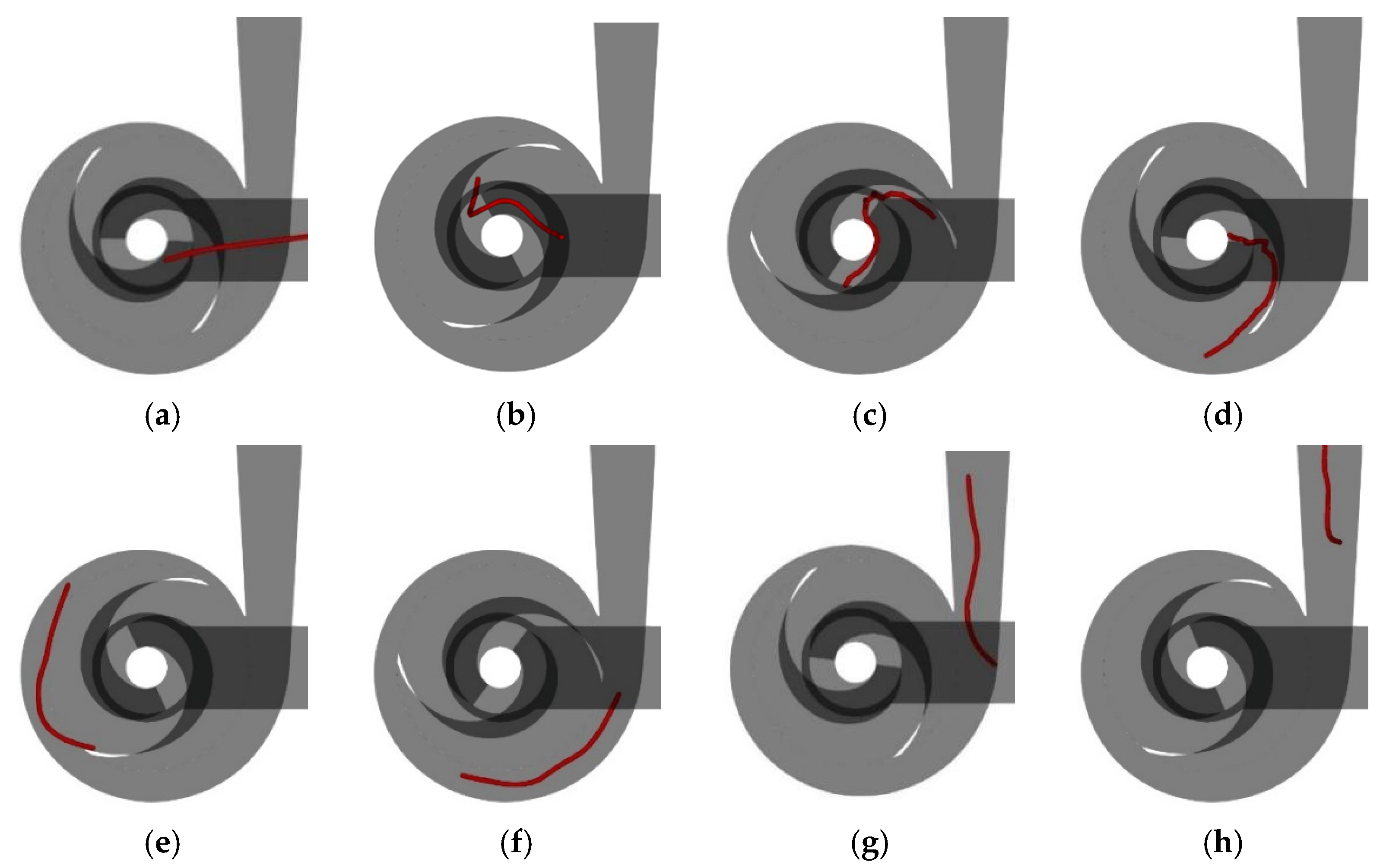
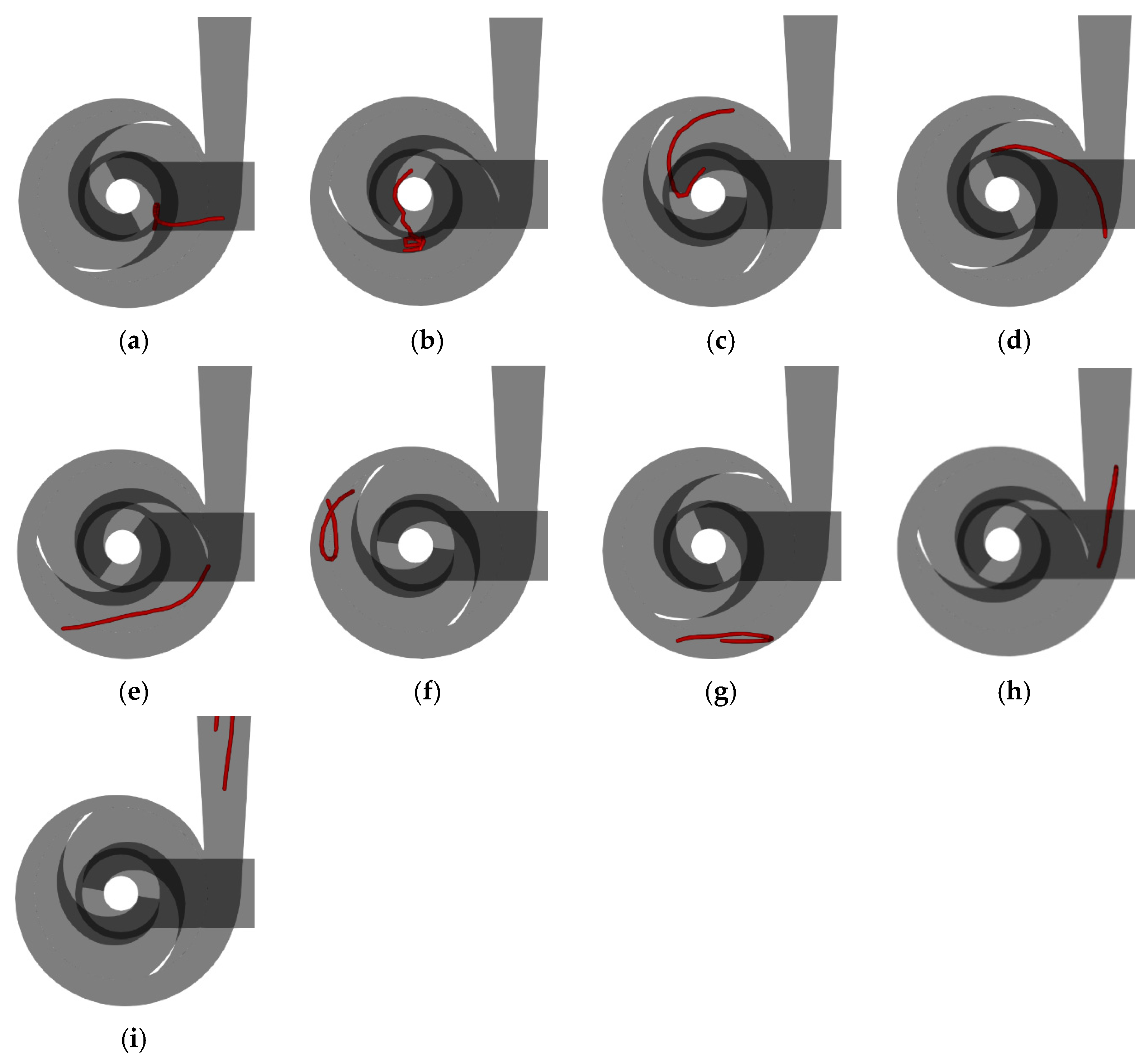
Figure 9 illustrates the fiber flow with a density of 300 kg/m3 in the double-blade pump. It can be observed from Figure 9 that after the flexible fiber enters the double-blade non-clogging pump, the front portion contacts the impeller suction surface without bending; instead, it moves towards the middle of the blade along the suction surface. The rear half of the fiber bends and forms wrinkles under the push of the blade edge after flowing into the impeller, and the flexible fiber simultaneously flows towards the outer side of the blade and gradually stretches out. When the flexible fiber enters the volute, it does not collide with the volute tongue and flows smoothly out of the double-blade non-clogging pump.
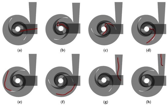
Figure 9.
The fiber flow with a density of 300 kg/m3 in the double-blade pump: (a) t = 0.1995 s; (b) t = 0.2660 s; (c) t = 0.3315 s; (d) t = 0.3990; (e) t = 0.4655 s; (f) t = 0.5320 s; (g) t = 0.5985 s; (h) t = 0.6650 s.
Figure 10 shows the fiber flow with a density of 732 kg/m3 in the double-blade pump. It can be observed from Figure 10 that the flexible fiber collides with the blade when entering the impeller of the double-blade non-clogging pump, resulting in the aggregation of the front half of the fiber. As the liquid phase flows, the agglomerated front half of the fiber gradually stretches out and flows to the outside of the blade, moving towards the tail of the blade. After the flexible fiber enters the volute, due to the position of the fiber entering the volute being below and close to the tongue, the middle section of the flexible fiber collides with the tongue, causing the flexible fiber to bend and continue to rotate within the volute for one round before flowing out of the volute.
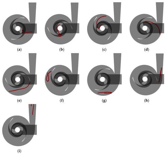
Figure 10.
The fiber flow with a density of 732 kg/m3 in the double-blade pump: (a) t = 0.2660 s; (b) t = 0.3315 s; (c) t = 0.3990 s; (d) t = 0.4655 s; (e) t = 0.5320 s; (f) t = 0.5985 s; (g) t = 0.6650 s; (h) t = 0.7315 s; (i) t = 0.7980 s.
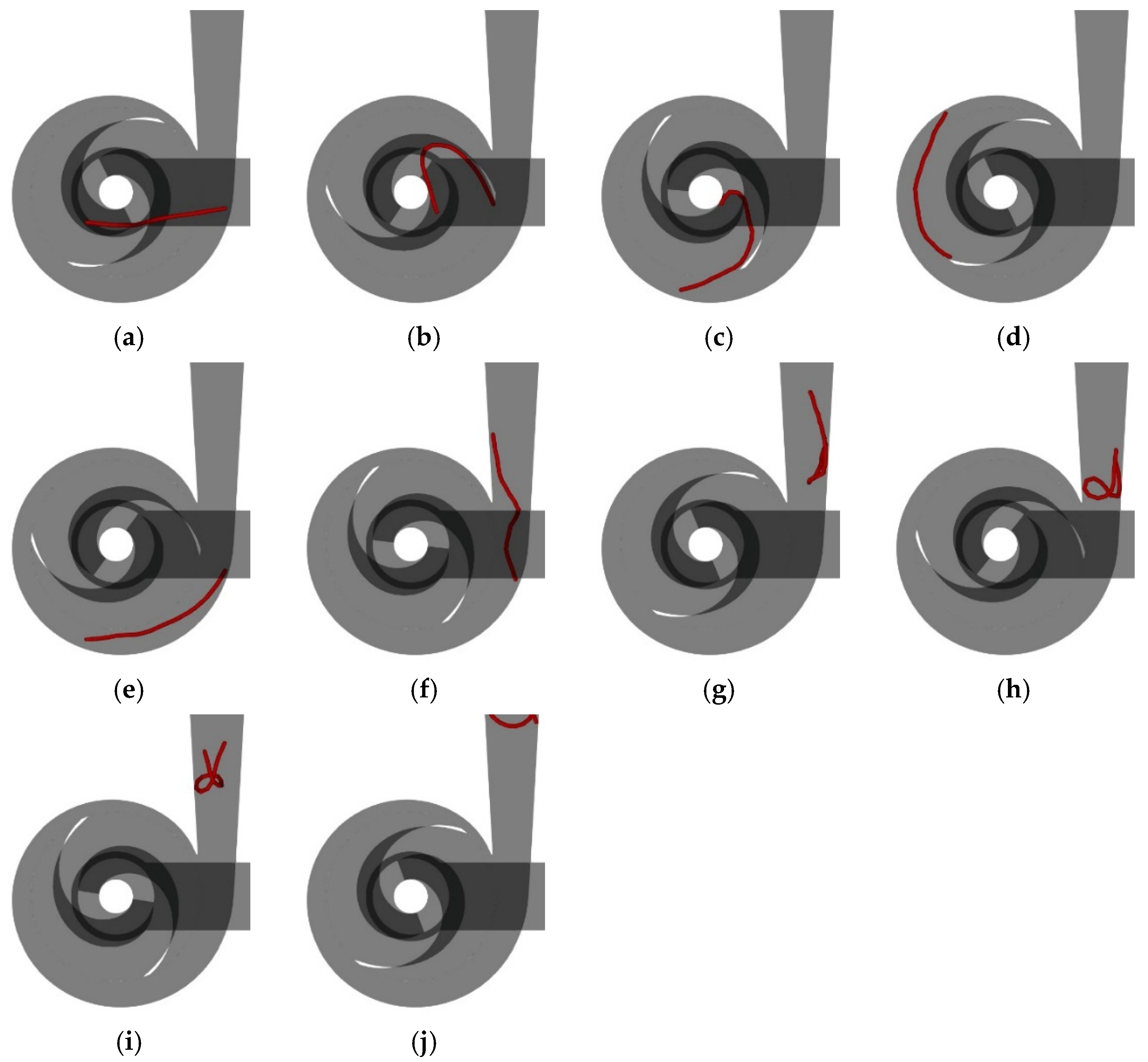
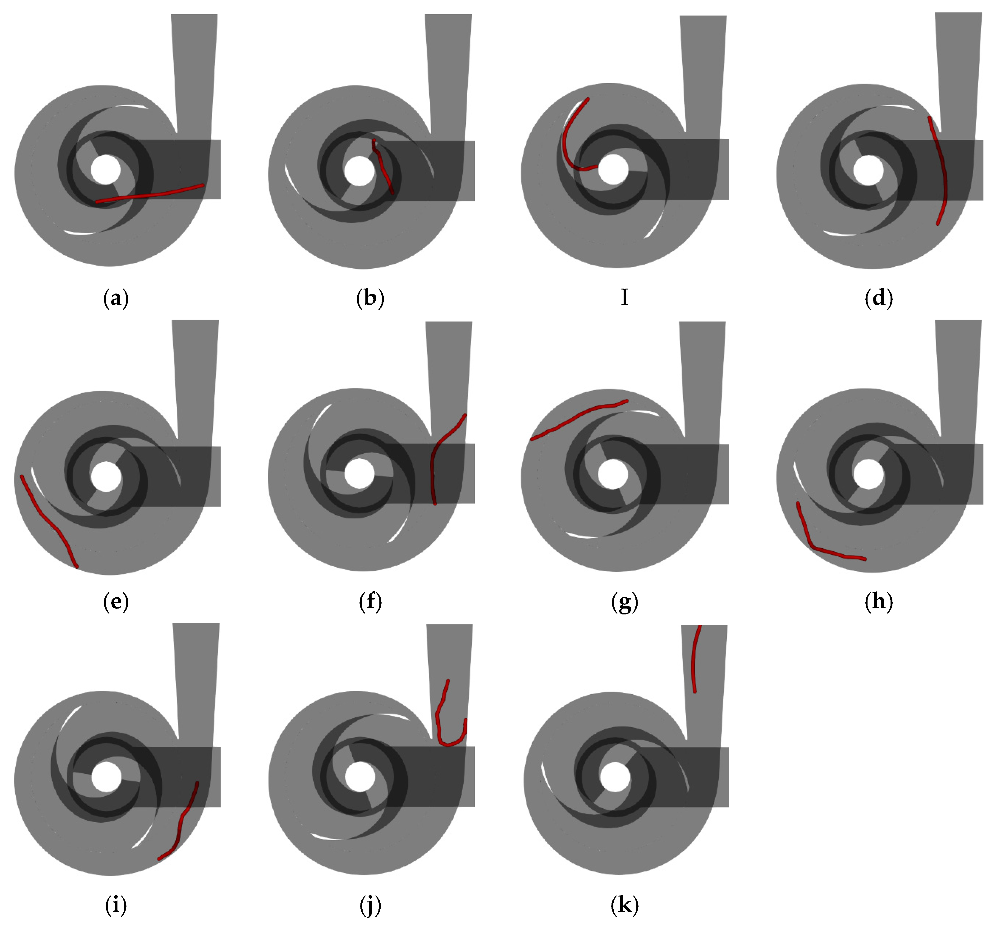
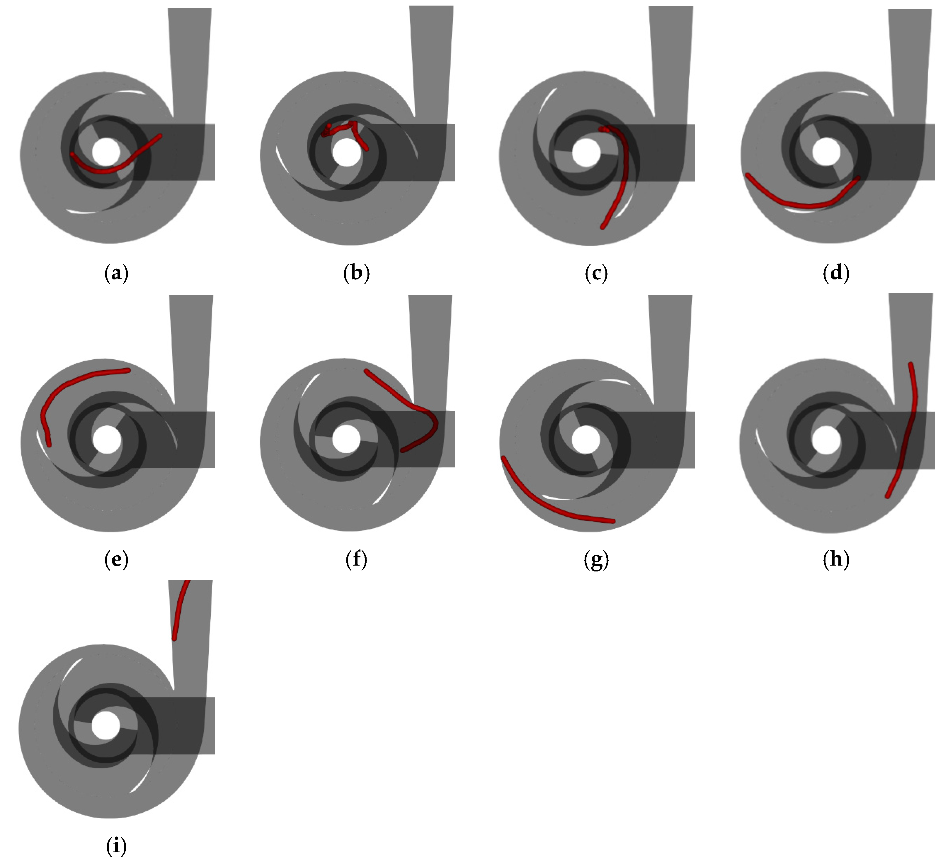
Figure 11 shows the fiber flow with a density of 920 kg/m3 in the double-blade pump. It can be observed from Figure 11 that after the flexible fiber enters the double-blade non-clogging pump, the front half contacts the suction surface of the blade and moves towards the middle of the blade. Under the push of the inlet edge of the blade, the flexible fiber bends, and the front half of the fiber continues to flow towards the tail of the blade, pushing the back half of the fiber to move from the outside of the blade away from the inlet edge towards the outer edge of the impeller. The flexible fiber does not collide with the tongue after entering the volute, but after entering the diffusion section, the fiber contacts the wall of the volute. Under the action of wall friction and turbulence disturbance, the flexible fiber bends and agglomerates in the diffusion section, leading to a decrease in the fiber flow velocity.
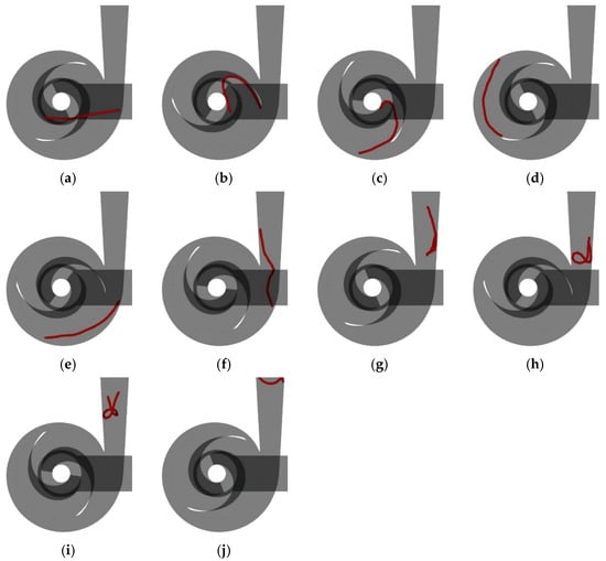
Figure 11.
The fiber flow with a density of 920 kg/m3 in the double-blade pump: (a) t = 0.2660 s; (b) t = 0.3315 s; (c) t = 0.3990 s; (d) t = 0.4655 s; (e) t = 0.5320 s; (f) t = 0.5985 s; (g) t = 0.6650 s; (h) t = 0.7315 s; (i) t = 0.7980 s; (j) t = 0.8645 s.
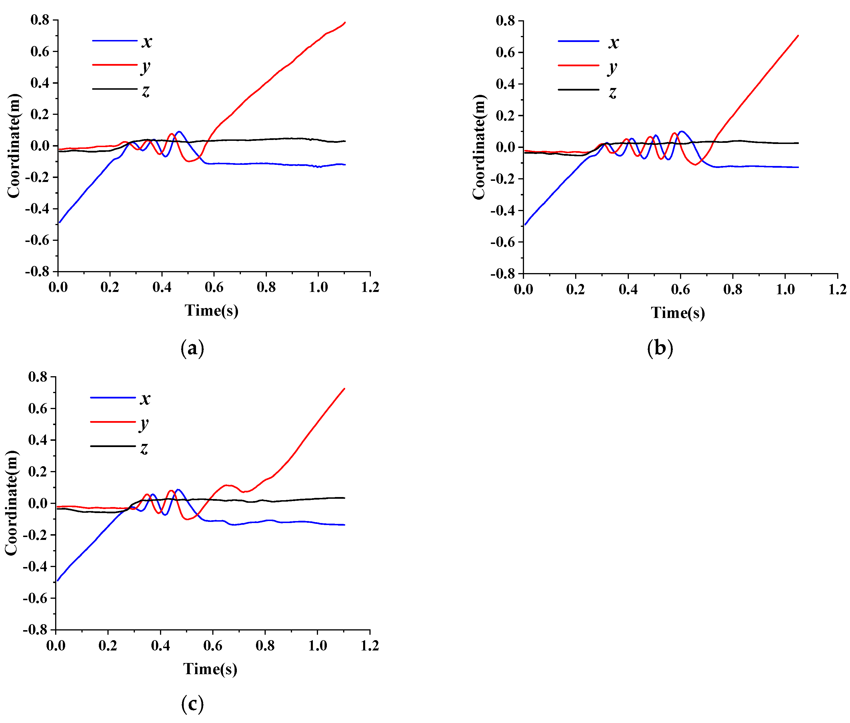
To analyze the location changes of flexible fiber flowing in the double-blade non-clogging pump and the time it takes to pass through the pump, a spatial Cartesian coordinate system is established with the axis at the impeller inlet as the coordinate origin, the inlet flow direction of the flexible fiber as the positive x-axis direction, the outlet flow direction as the positive y-axis direction and the direction of the impeller rotation axis as the negative z-axis direction. The average coordinates of the flexible fiber on the x-, y- and z-axes when flowing inside the double-blade pump are taken, respectively, and a graph depicting the average coordinates of flexible fiber in the pump is plotted.
Figure 12 illustrates the average coordinates of flexible fibers with different densities in the double-blade pump. Based on the average coordinate analysis, for the flexible fiber with a density ρ of 300 kg/m3, it enters the impeller at t of 0.22 s, rotates three times in the double-blade pump and progresses into the volute diffusion section at a t of 0.58 s. The flexible fiber flows slowly along the y-axis in the outlet pipeline and flows out of the outlet extension section at a t of 1.11 s. In the case of the flexible fiber with a density ρ of 732 kg/m3, it enters the impeller at a t of 0.25 s, circles four times in the pump, enters the volute diffusion section at a t of 0.73 s and flows out of the outlet extension section at a t of 1.08 s. For the flexible fiber with a density ρ of 920 kg/m3, it enters the impeller at t of 0.27 s, rotates for two cycles in the double-blade non-clogging pump and enters the volute diffusion section at a t of 0.57 s. However, the fiber aggregates in the volute diffusion section due to wall friction and turbulence disturbance, causing fluctuations in the y-axis average coordinate of the flexible fiber. Finally, the fiber flows out of the outlet extension section at a t of 1.11 s.
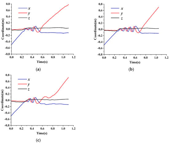
Figure 12.
Average coordinates of flexible fibers with different densities in the double-blade pump: (a) ρ = 300 kg/m3; (b) ρ = 732 kg/m3; (c) ρ = 920 kg/m3.
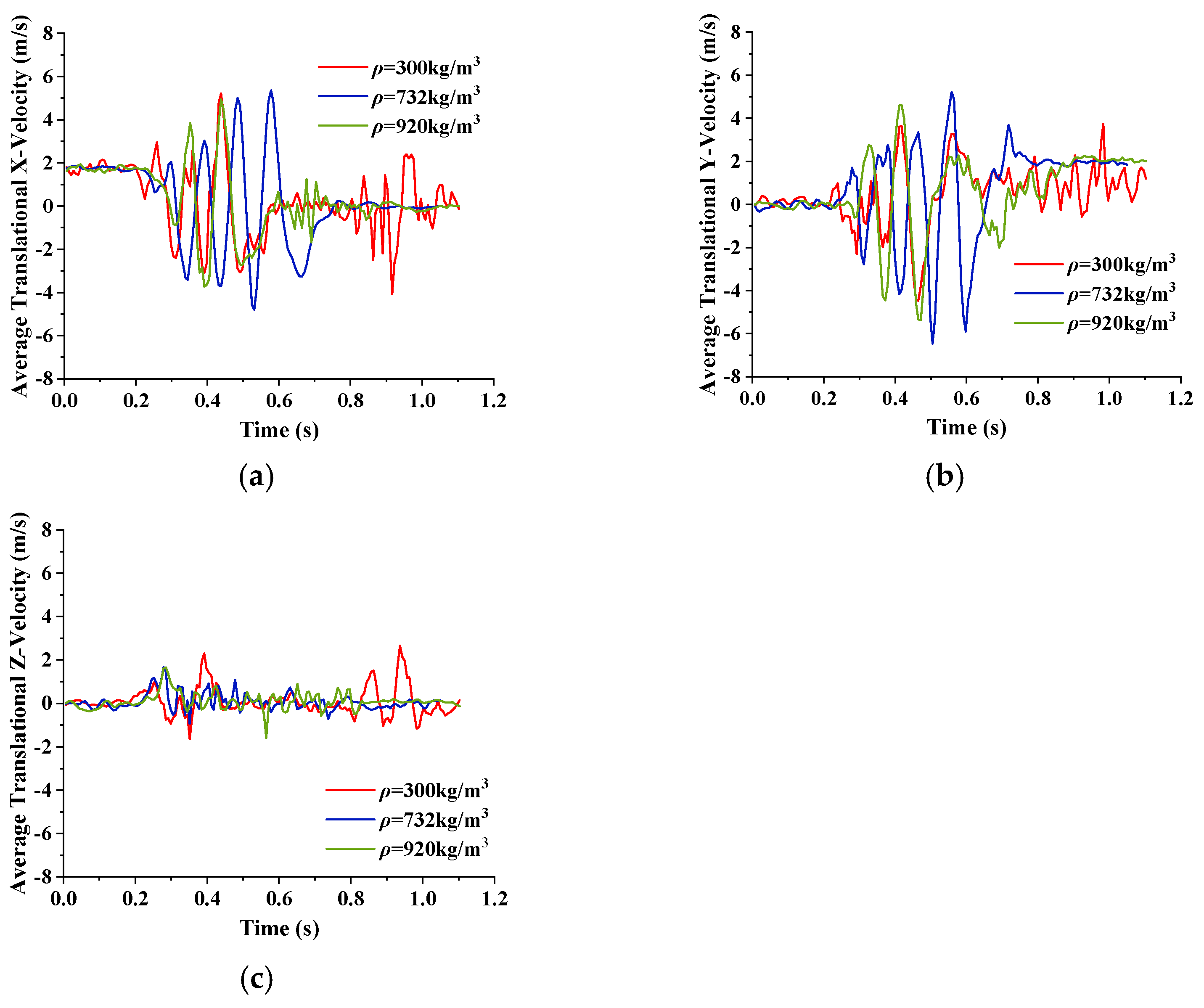
Figure 13 shows the average velocity of flexible fibers with different densities in the double-blade pump. Comparing the average velocities of flexible fibers with different densities in different directions, it can be identified that as the fiber density increases, the time point of the fibers into the impeller of the double-blade non-clogging pump is delayed, causing a phase difference. Concurrently, as the density of the fibers increases, within the same period, the extreme values of the average velocities of the fibers along the x- and y-axes in the double-blade non-clogging pump also increase. When the density ρ is 300 kg/m3, the flexible fiber in the extended outlet section experiences turbulence, resulting in significant disturbances to the average velocities along the x-, y-, and z-axes. The frequent contact between the flexible fiber and the wall leads to a decrease in the average value of the fluctuation range of the average velocity along the y-axis. This prolongs the time for the flexible fiber to flow out of the extended outlet section. When the density ρ is 732 kg/m3, the fiber bends upon entering the impeller, causing a decrease in peak values of average velocities for the fibers in the x and y directions during the initial cycle. However, in the subsequent rotational cycles, the average velocity peak values of the fiber exceed those of the flexible fiber with a density ρ of 300 kg/m3. Lastly, when the density ρ is 920 kg/m3, the peak values of the average velocity of the fiber further increase.
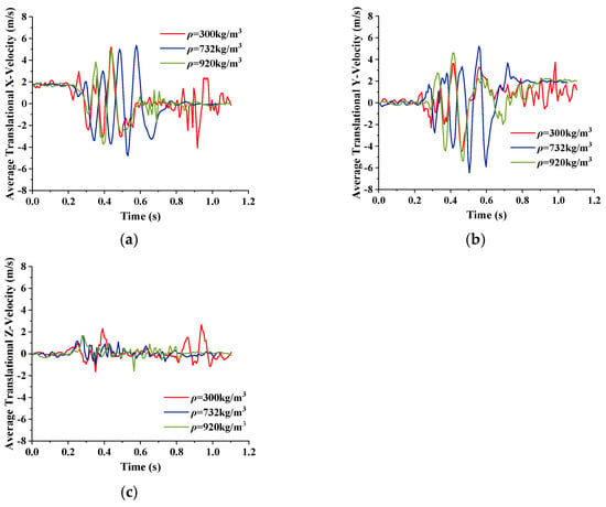
Figure 13.
The average velocity of flexible fibers with different densities in the double-blade pump: (a) x-axis; (b) y-axis; (c) z-axis.
4.2. Flow Characteristic Analysis of Fibers with Different Lengths in a Double-Blade Non-Clogging Pump
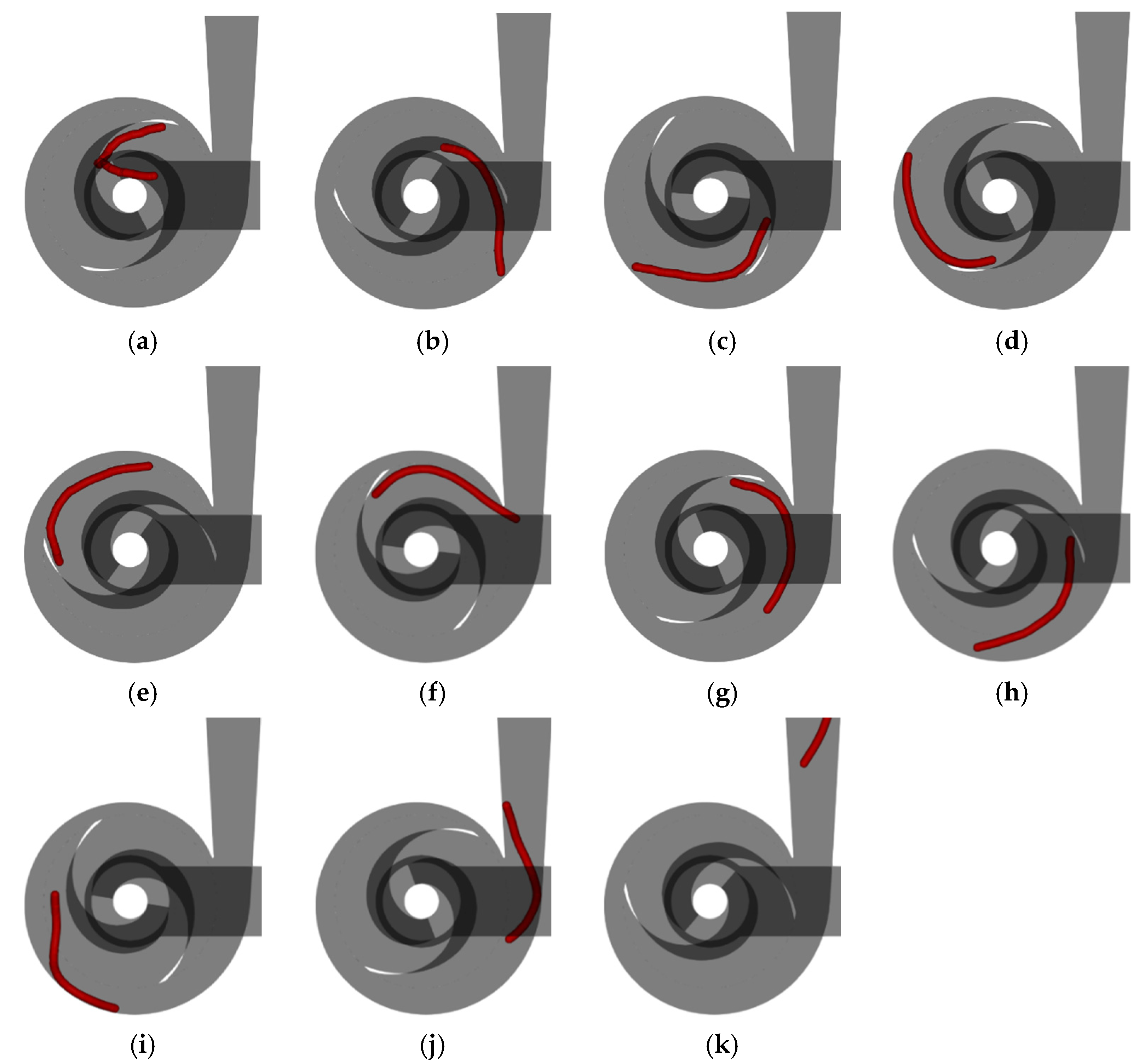
Figure 14 shows the fiber flow with a length of 150 mm in the double-blade pump. It can be observed from Figure 14 that when the fiber length L is 150 mm, the fiber does not agglomerate in the double-blade non-clogging pump at a rated flow rate. The fiber enters the pump from the outer side of one blade, moves towards the suction side of the other blade, and has already flowed out of the impeller along the suction surface of the blade and entered the volute when t is 0.4655 s. During the flow process in the volute, the fiber collides with the tongue when it first flows near the diffusion section of the volute, causing the fiber to continue to rotate in the volute for one more cycle before exiting the volute.
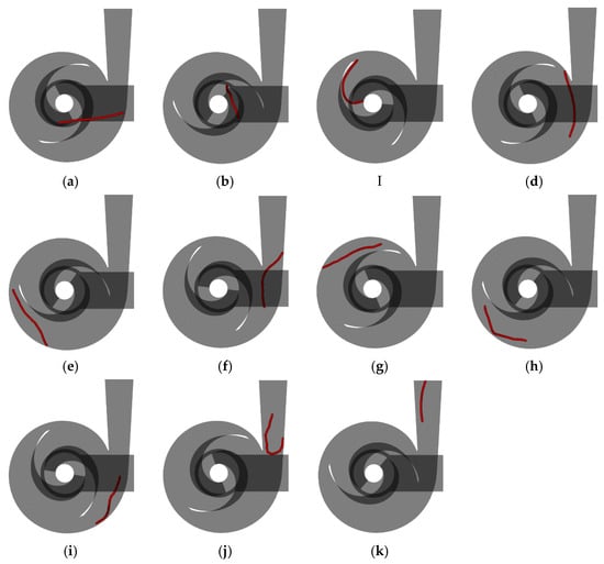
Figure 14.
The fiber flow with a length of 150 mm in the double-blade pump. (a) t = 0.2660 s; (b) t = 0.3315 s; (c) t = 0.3990 s; (d) t = 0.4655 I(e) t = 0.5320 s; (f) t = 0.5985 s; (g) t = 0.6650 s; (h) t = 0.7315 s; (i) t = 0.7980 s; (j) t = 0.8645 s; (k) t = 0.9310 s.
The flow condition of the flexible fiber with a length L of 200 mm in a double-blade non-clogging pump is shown in Figure 10. After entering the impeller, the fiber collides with the suction surface of another blade at the inlet edge of the blade, causing aggregation in the first half of the fiber. As the liquid phase flows, the aggregated first half of the fiber gradually stretches and moves from the outer side of the blade to the tail of the blade, eventually exiting the impeller. During the flow in the volute, the fiber collides with the tongue, causing the fibers to bend and continue to rotate within the volute for one more cycle before exiting the volute.
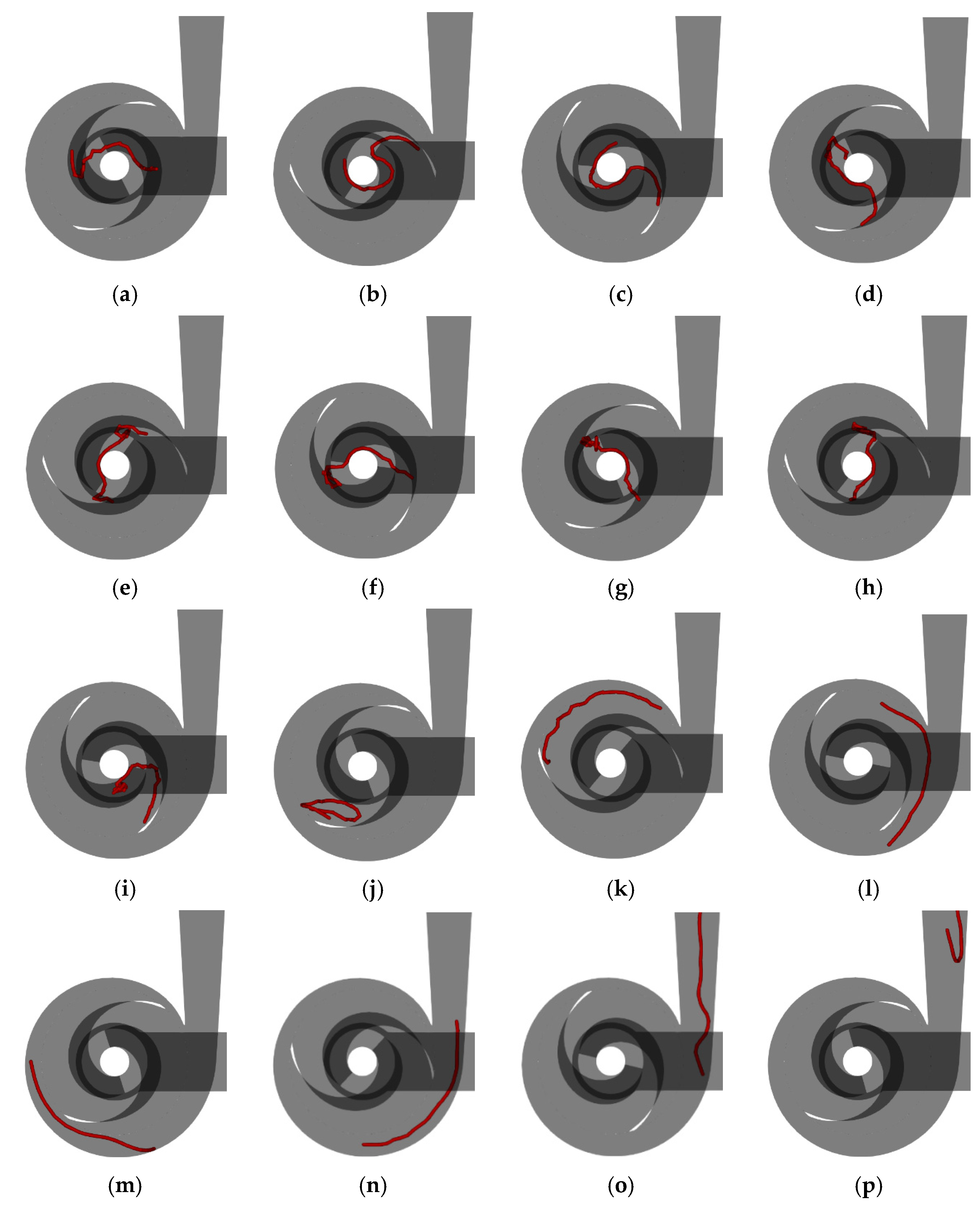
Figure 15 illustrates the fiber flow with a length of 250 mm in the double-blade pump. It can be observed from Figure 15 that after the fiber enters the impeller, the front half flows towards the outer side of the blade, but the latter half wraps around the pump shaft, preventing the fiber from continuing to move towards the outer side of the blade. During this period, the ends of the fiber continually collide with the blade wall, leading to bending or aggregation on both ends, causing the fiber to remain in the center of the impeller. Within this process, the fiber gradually moves to one side, and at a t of 0.7980 s, the front half of the fiber flows again towards the outer side of the blade and drags the latter half of the fiber to move to the outer side of the blade. In this procedure, the fiber is influenced by the vortex flow and forms a ring shape, then gradually stretches out, and after sufficient centrifugal movement inside the volute, it exits the volute.
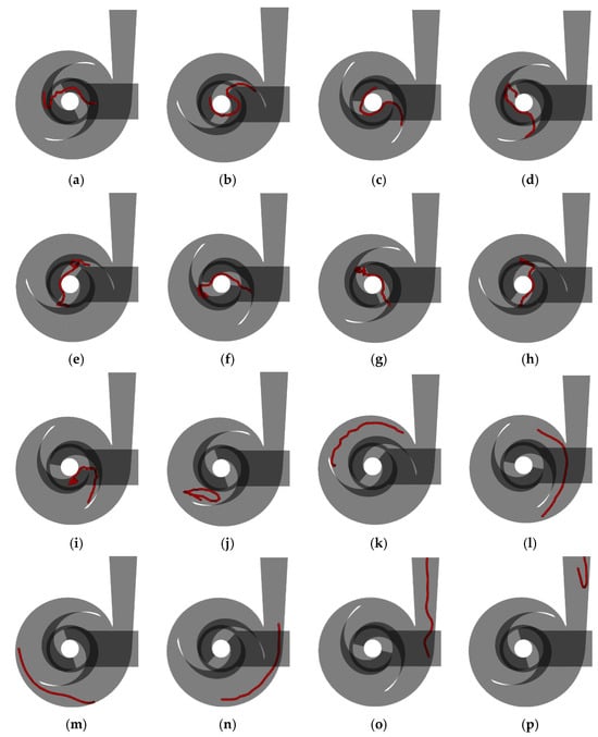
Figure 15.
The fiber flow with a length of 250 mm in the double-blade pump: (a) t = 0.2660 s; (b) t = 0.3315 s; (c) t = 0.3990 s; (d) t = 0.4655 s; (e) t = 0.5320 s; (f) t = 0.5985 s; (g) t = 0.6650 s; (h) t = 0.7315 s; (i) t = 0.7980 s; (j) t = 0.8645 s; (k) t = 0.9310 s; (l) t = 0.9975 s; (m) t = 1.0640 s; (n) t = 1.1305 s; (o) t = 1.1970 s; (p) t = 1.2635 s.
In summary, as the length of the fiber increases, it is more likely to collide and aggregate within the double-blade non-clogging pump, leading to a prolonged passage time for the fiber through the pump. When the fiber length reaches 250 mm, the latter half of the flexible fiber will wrap around the pump shaft after entering the impeller, temporarily preventing the smooth outflow of the fiber. Meanwhile, collisions between the ends of the fiber and the suction surface of the blade also hinder the fiber from flowing outward, so it takes a long time for the fiber to leave the center of the impeller. Therefore, it can be inferred that as the length of the fiber continues to increase, the capacity of the double-blade non-clogging pump to smoothly pass fibers decreases.
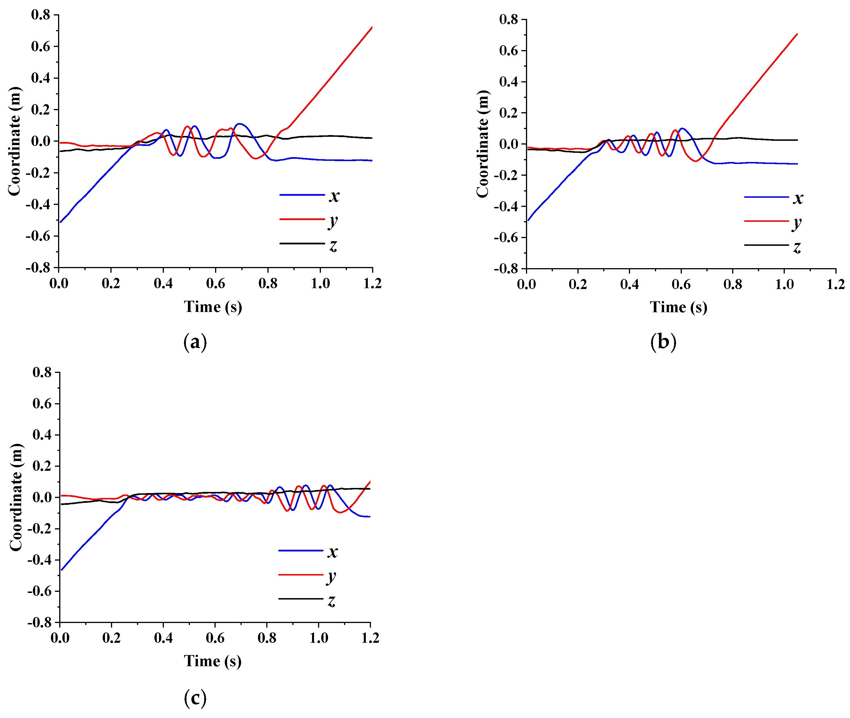
Figure 16 presents the average coordinates of flexible fibers with different length in the double-blade pump. It can be observed from Figure 16 that when the flexible fiber length L is 150 mm, the fiber flows into the impeller when t is 0.29 s and enters the diffusion section of the volute after rotating for three cycles in the double-blade non-clogging pump. According to the aforementioned analysis of the flow status, it is noted that the flexible fiber is close to the diffusion section of the volute after completing the second round of rotation, but the collision of the middle of the fiber with the tongue results in the fiber continuing to rotate for another lap in the volute. When t is 0.83 s, the flexible fiber enters the diffusion section of the volute, and when t is 1.22 s, the fiber flows out from the outlet extension section.
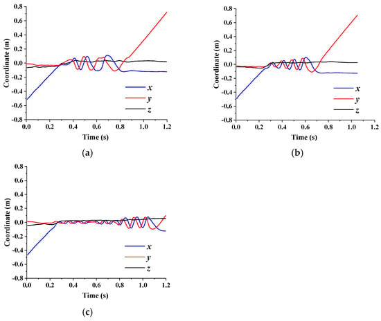
Figure 16.
Average coordinates of flexible fibers with different lengths in the double-blade pump: (a) L = 150 mm; (b) L = 200 mm; (c) L = 250 mm.
When the length of the flexible fiber L is 200 mm, the fiber flows into the impeller at a t of 0.25 s and enters the diffusion section of the volute after rotating four laps in the double-blade non-clogging pump. Similar to the flexible fiber with a length L of 150 mm, the fiber with a length L of 200 mm collides with the tongue when it first enters the volute diffusion section after rotating three times, causing the fiber to continue rotating in the volute for one cycle. Compared to the fiber with a length L of 150 mm, the fiber with a length L of 200 mm stays in the impeller for a longer duration but with a shorter rotation period; hence, it enters the diffusion section of the volute faster. The flexible fiber enters the diffusion section of the volute at a t of 0.72 s, and it flows out from the extended section of the outlet at a t of 1.08 s.
When the length of the flexible fiber L is 250 mm, the fiber enters the impeller at a t of 0.22 s. Unlike the fibers with the lengths of 150 mm and 200 mm, the fiber with a length of 250 mm wraps around the pump shaft and cannot be detached after entering the double-blade non-clogging pump. This results in the fiber remaining at the center of the impeller for a considerable length of time, during which the average coordinates of the fiber on the x- and y-axes fluctuate within a minimal range. It is not until a t of 0.78 s that the fiber detaches from the center of the impeller and moves towards the outer edge of the impeller. After rotating for more than three laps, the fiber enters the diffusion section of the volute at a t of 1.17 s and flows out from the extension of the outlet at a t of 1.53 s.
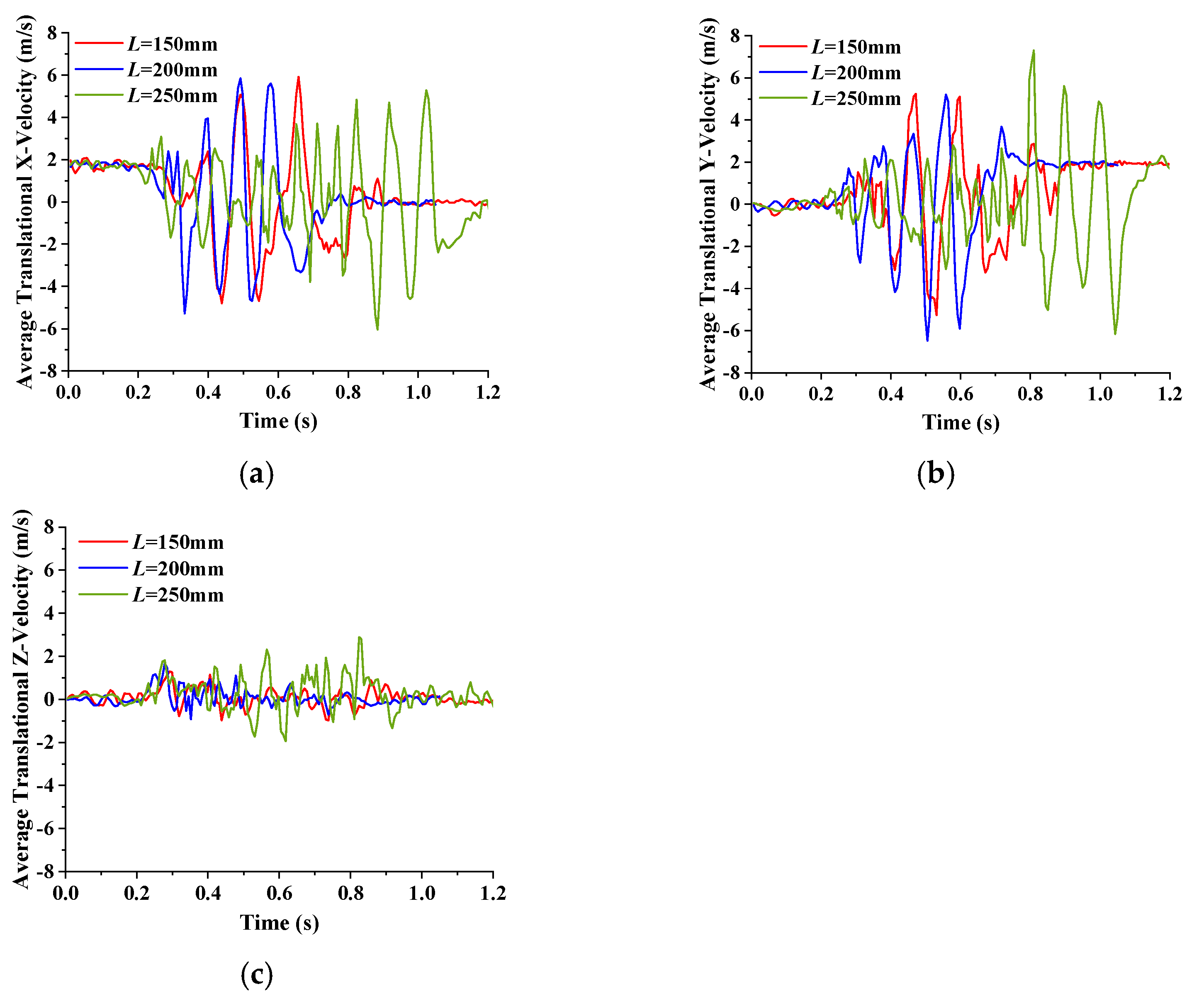
Figure 17 shows the average velocity of flexible fibers with different lengths inside the double-blade pump. It can be inferred from Figure 17 that due to the increased length of the flexible fiber, the front end of the fiber is closer to the impeller when the fiber enters the inlet extension section from the solid phase entrance. Therefore, as the fiber length increases, the time for the fiber to enter the impeller moves forward. After the flexible fibers with an L of 150 mm and 200 mm enter the impeller, the average velocity of the flexible fibers along the x-axis and y-axis in the double-blade non-clogging pump fluctuate periodically, and the fluctuation peaks are essentially consistent. However, the fluctuation period of the average velocity for the fiber with a length L of 200 mm is shorter because compared to the flexible fiber with a length L of 150 mm, the fiber with a length L of 200 mm stays longer in the center of the impeller and has a shorter rotation period. Consequently, the fiber with a length L of 200 mm enters the diffusion section of the volute faster. Considering the overall flow characteristics of the flexible fibers, it can be concluded that the passage efficiency of the flexible fiber with a length L of 150 mm is higher than that of the fiber with a length L of 200 mm.
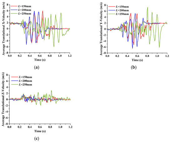
Figure 17.
Average velocity of flexible fibers with different lengths inside the double-blade pump: (a) x-axis; (b) y-axis; (c) z-axis.
When the length of the flexible fiber is 250 mm, the fiber stays in the center of the impeller for a significant period of time after entering the impeller, exhibiting slight periodic fluctuations in average coordinates. Consequently, the fluctuations in average velocity along the x-axis and y-axis for the fiber are much smaller compared to fibers of other lengths within the same time period. It is not until a t of 0.78 s that the fiber separates from the center position of the impeller that the fluctuation range of the average velocity of the fiber along the x-axis and y-axis directions increased to the normal range. Due to the influence of the fiber length, the flexible fiber with a length L of 250 mm often comes into contact with the wall surface of the double-blade non-clogging pump during the flow process and even bends. As a result, the fluctuations in average velocity along different directions for the fiber with a length L of 250 mm are more chaotic.
4.3. Flow Characteristic Analysis of Fibers with Different Diameters in a Double-Blade Non-Clogging Pump
The flow condition of flexible fibers with the diameter dp of 5 mm in the double-blade non-clogging pump is shown in Figure 10. When the fiber enters the impeller, the front edge bends and coalesces, but it quickly stretches out with the flow. After departing from the outer side of the blade, they smoothly flow towards the tail end of the blade.
Figure 18 shows the fiber flow with a diameter of 7.5 mm in the double-blade pump. Similar to the fiber with a diameter dp of 5 mm, the fiber with a diameter dp of 7.5 mm also collides with the suction surface of the blade after entering the impeller and then bends under the pressure between the suction surface and the edge of the inlet. However, due to the increase in fiber diameter, the bending resistance of the fiber is increased, so the fiber does not agglomerate and only bends to a certain extent. It quickly recovers with the flow of the fiber, and no further bending occurs afterwards, smoothly flowing out of the impeller. Upon entering the volute, the fiber collides with the tongue. Due to the increased bending resistance, the fiber does not bend but continues to stretch after the collision, rotating within the volute for a cycle before entering the diffusion section of the volute.
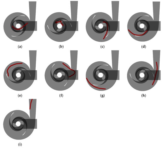
Figure 18.
The fiber flow with a diameter of 7.5 mm in the double-blade pump: (a) t = 0.2660 s; (b) t = 0.3315 s; (c) t = 0.3990 s; (d) t = 0.4655 s; (e) t = 0.5320 s; (f) t = 0.5985 s; (g) t = 0.6650 s; (h) t = 0.7315 s; (i) t = 0.7980 s.
Figure 19 illustrates the fiber flow with a diameter of 10 mm in the double-blade pump. It can be inferred from Figure 19 that with the increase in fiber diameter, the bending resistance of the fiber further enhances. When the flexible fiber flows to the tail of the blade, the front end of the fiber contacts the tail of the blade, while the rear end contacts the wall of the volute. At this time, due to the thick diameter and strong resistance of the flexible fiber, it results in the fiber being squeezed by the walls at both ends, and it cannot quickly detach from the tail of the blade. Meanwhile, during the rotation of the flexible fiber, the tongue continuously strikes the latter half of the fiber, further hindering the fiber from leaving the blade tail and entering the volute.
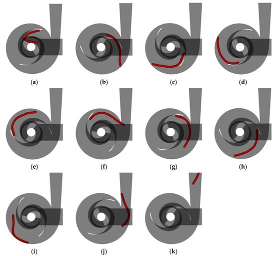
Figure 19.
The fiber flow with a diameter of 10 mm in the double-blade pump: (a) t = 0.2660 s; (b) t = 0.3315 s; (c) t = 0.3990 s; (d) t = 0.4655 s; (e) t = 0.5320 s; (f) t = 0.5985 s; (g) t = 0.6650 s; (h) t = 0.7315 s; (i) t = 0.7980 s; (j) t = 0.8645 s; (k) t = 0.9310 s.
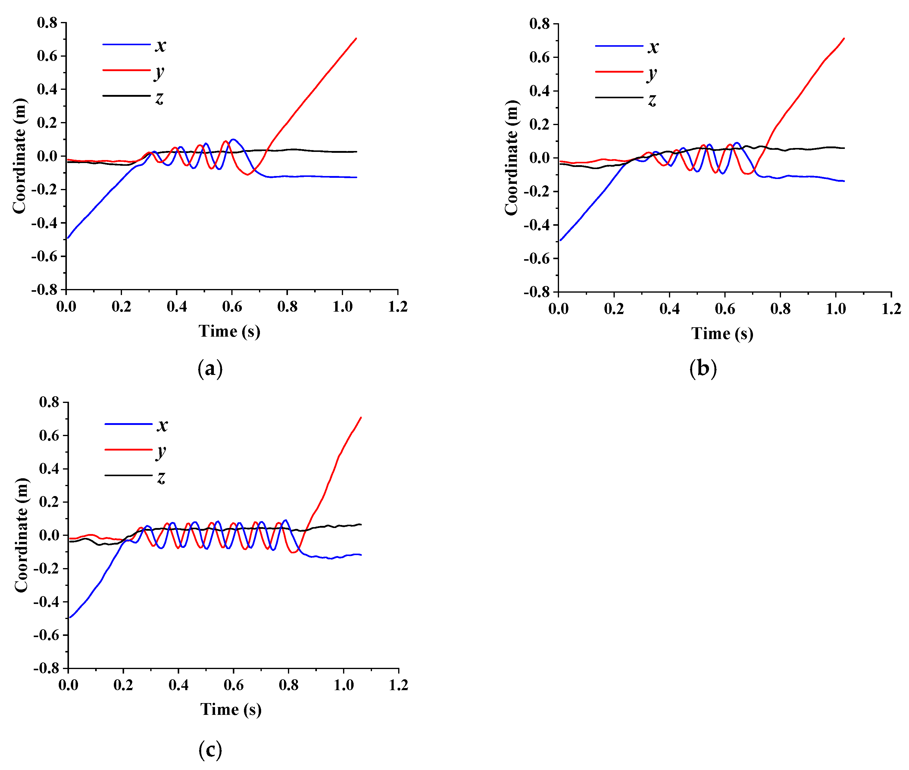
Figure 20 shows the average coordinates of flexible fibers with different diameters in the double-blade pump. It can be observed from Figure 20 that the flexible fiber with a diameter dp of 5 mm enters the impeller at a t of 0.25 s and rotates four times in the double-blade non-clogging pump before entering the diffuser section of the volute. When the fiber first enters the diffusion section of the volute after three cycles of rotation, it collides with the tongue, causing the fiber to continue to rotate within the volute for one cycle. At a t of 0.72 s, the flexible fiber enters the diffuser section of the volute and flows out from the outlet extension at a t of 1.08 s. The flexible fiber with a diameter dp of 7.5 mm enters the impeller at a t of 0.23 s and rotates four times in the double-blade non-clogging pump before entering the diffuser section of the volute. Before the first rotation cycle, the flexible fiber bends under the compression of the blade suction surface and inlet edge, staying at the center of the impeller, resulting in a small range of fluctuations in the x-axis coordinates before the first rotation cycle. The flexible fiber with a diameter dp of 10 mm enters the impeller at a t of 0.21 s and rotates seven times in the double-blade non-clogging pump before entering the diffuser section of the volute. Based on the previous analysis of the flow state, it can be inferred that the flexible fiber reaches the outer edge of the impeller after three rotations. At this point, due to the contact between the front end of the fiber and the blades, the contact between the rear end and the volute wall and the multiple collisions with the tongue, the flexible fiber is unable to smoothly detach from the tail of the blade. It is not until a t of 0.86 s that the flexible fiber enters the diffuser section of the volute, and at a t of 1.08 s, it flows out from the outlet extension.
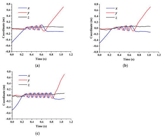
Figure 20.
Average coordinates of flexible fibers with different diameters in the double-blade pump: (a) dp = 5 mm; (b) dp = 7.5 mm; (c) dp = 10 mm.
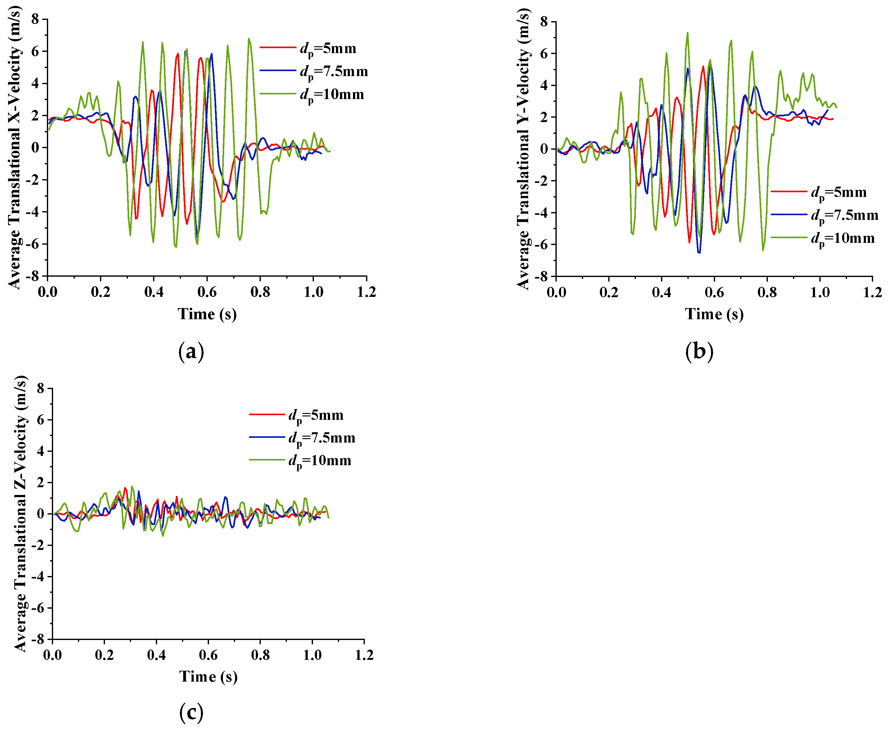
Figure 21 shows the average velocity of flexible fibers with different diameters in the double-blade pump. It can be observed from Figure 21 that when the double-blade non-clogging pump transports flexible fibers with a diameter dp of 5 mm and 7.5 mm, although the average velocity peak of the diameter dp of 7.5 mm shifts back due to bending at the impeller inlet, the peak values of the average velocity of the flexible fibers with a diameter dp of 5 mm and 7.5 mm along the x-axis and y-axis are basically consistent. The peak value of the average velocity along the x-axis and y-axis is higher for the flexible fiber with a diameter dp of 10 mm, and the average velocity along the y-axis is higher for the flexible fiber after entering the outlet extension section.
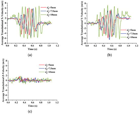
Figure 21.
Average velocity of flexible fibers with different diameters in the double-blade pump: (a) x-axis; (b) y-axis; (c) z-axis.
5. Discussion
5.1. The Ability of Different Density Fibers to Pass through the Double-Blade Non-Clogging Pump
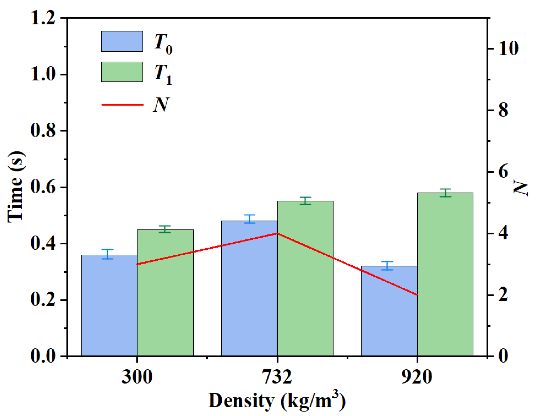
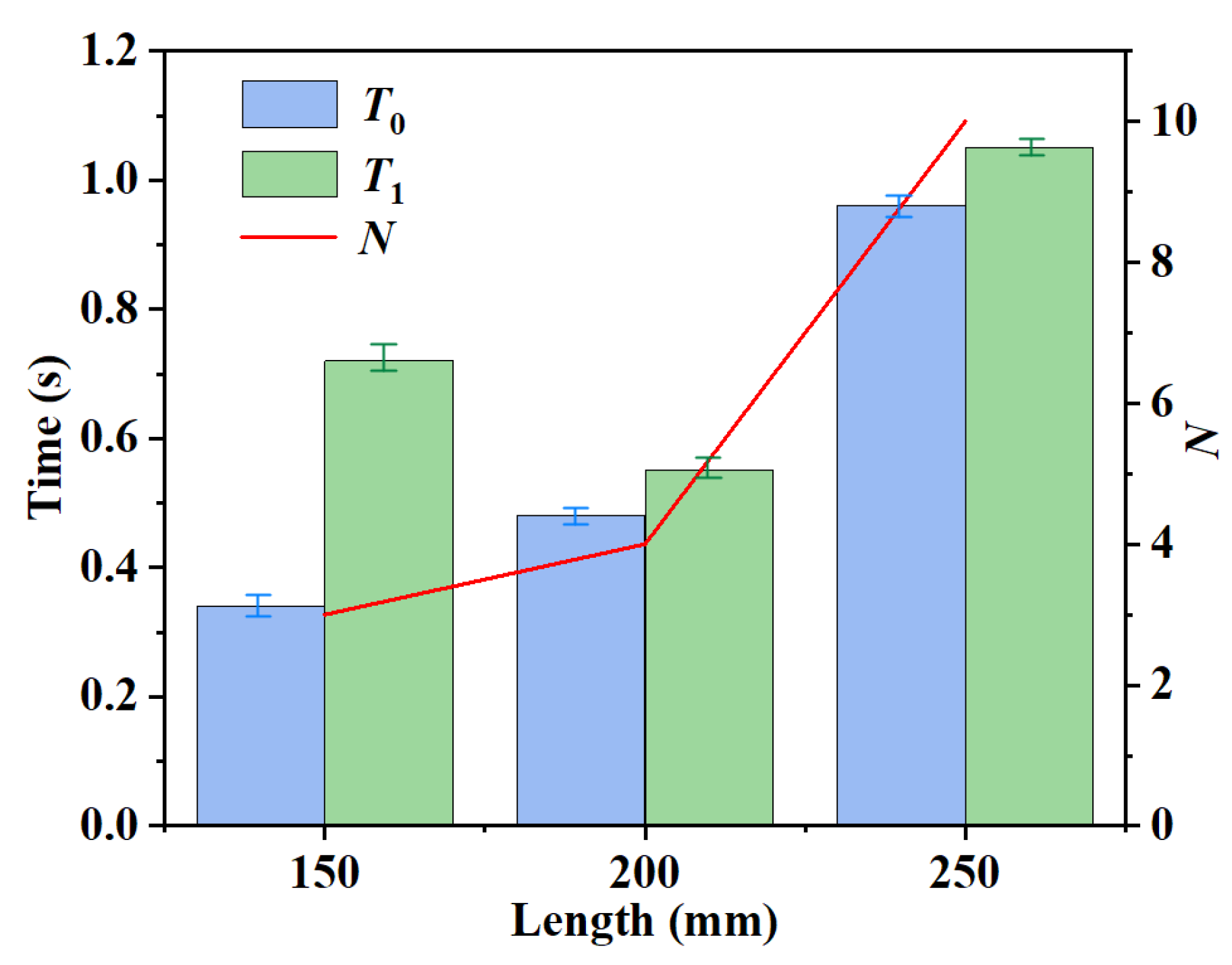
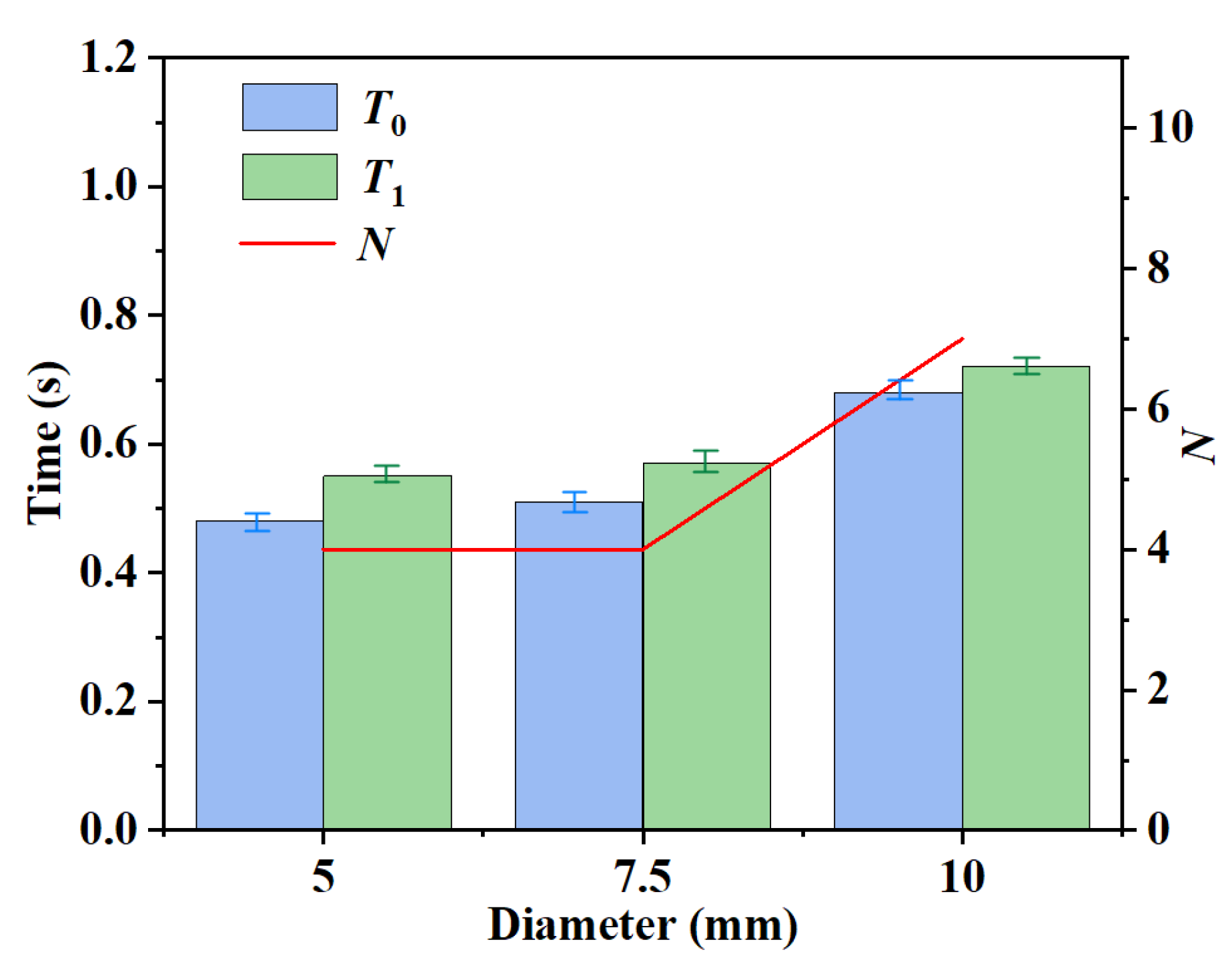
Analyzing the duration for flexible fibers to pass through the non-clogging pump, the position of fibers can be determined based on the average coordinates of the flexible fibers. T1 is defined as the duration of time from the flexible fibers entering the impeller to exiting the volute diffusion section, reflecting the time required for fibers to completely pass through the non-clogging pump. However, due to the influence of fiber morphology, a collision between the fiber and the tongue can lead to an increase in the time required for the fiber to pass through the non-clogging pump. Therefore, T0 is defined as the duration from the time the flexible fibers enter the impeller to when the fibers completely flow out of the impeller and pass through the volute diffusion section for the first time. T0 reflects the time required for the fibers to pass through the impeller of the non-clogging pump, excluding the interference caused by collision with the tongue due to fiber morphology. N is the rotation period of flexible fibers in the non-clogging pump.
Figure 22 shows the transport time of different density fibers. It can be seen that the time of the same density fiber passing through the pump is not much different. As the fiber density increases, T1 gradually increases. However, the T0 of the fiber with a density of 920 kg/m3 is the smallest. This is primarily because the fiber with a density of 920 kg/m3 only rotates two times before entering the volute diffusion section but comes into contact with the wall inside the volute diffusion section, leading to aggregation under the influence of turbulent disturbances, thus staying in the volute diffusion section for a long time. Therefore, based on T0 and the number of rotation cycles N, it can be determined that the fiber with a density of 920 kg/m3 has the strongest capacity to pass through the double-blade non-clogging pump. The capacity of the fiber with a density of 300 kg/m3 is next, and the fiber with a density of 732 kg/m3 has the poorest pass-through capability.
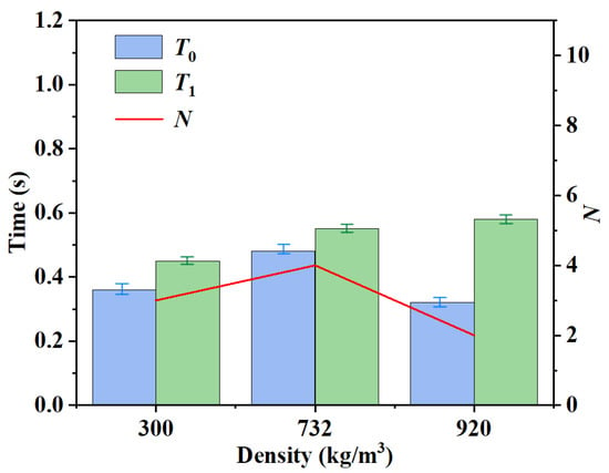
Figure 22.
The transport time of different density fibers.
Therefore, we can deduce that the ability of the fibers to pass through the non-clogging pump is related to the density of the fibers. Dense fibers are less affected by turbulent disturbances and have an increased ability to pass through a non-clogging pump.
5.2. The Ability of Different Length Fibers to Pass through the Double-Blade Non-Clogging Pump
Figure 23 presents the transport time of different fiber lengths. It can be found from Figure 23 that the time of fibers of the same length passing through the pump is close. The fiber with a length of 150 mm greatly extends T1 due to a collision with the tongue, but T0 and the number of rotation cycles N both increase correspondingly with the growth of the fiber length. Furthermore, the longer the fiber length, the greater the increase in T0 and N. Therefore, it is reasonable to infer that the passing capacity of the fiber decreases as the length of the fiber increases.
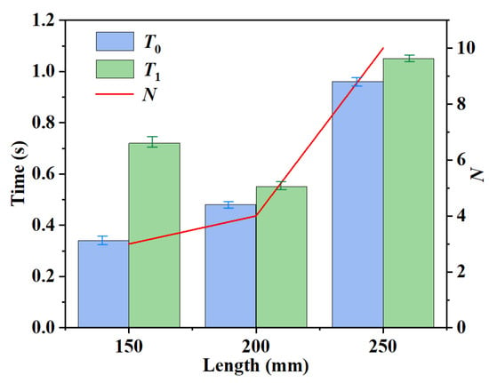
Figure 23.
The transport time of different length fibers.
We can deduce that the ability of the fiber to pass through the non-clogging pump is related to the length of the fiber. The longer the length of the fiber, the more the fiber will be wound in the pump, increasing the probability of collision with the diaphragm and decreasing the ability to pass through. Therefore, in the actual industry, the fiber length should be shortened as much as possible when the non-clogging pump transports the fiber, and the transportation time can be greatly shortened.
5.3. The Ability of Different Diameter Fibers to Pass through the Double-Blade Non-Clogging Pump
Figure 24 shows the transport time of different diameter fibers. It can be deduced Figure 24 that the time of fibers with the same diameter passing through the pump is not much different. The T0 and T1 values of the fiber with a diameter dp of 7.5 mm are slightly larger than those of the fiber with a diameter dp of 5 mm, and both fibers have a rotation cycle number N of 4. When the fiber diameter increases to 10 mm, the values of T0, T1 and N significantly increase. Therefore, it can be concluded that as the fiber diameter increases, the passing capacity of the flexible fiber in the double-blade non-clogging pump decreases.
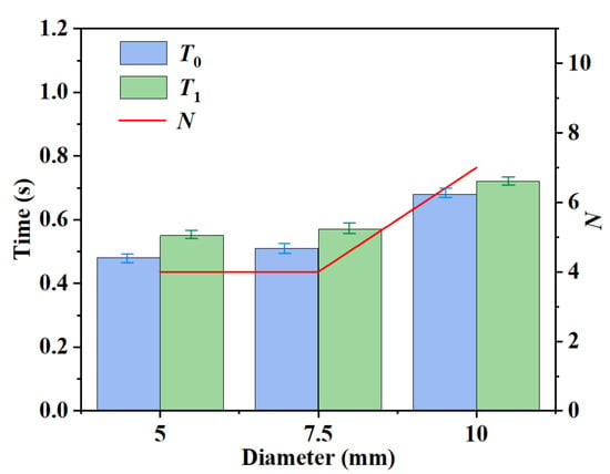
Figure 24.
The transport time of different diameter fibers.
We can deduce that the ability of the fibers to pass through a non-clogging pump is related to the diameter of the fibers. When the fiber diameter is small, the ability of the fiber to pass through the non-clogging pump is basically unchanged, but with the gradual increase between the fibers, the proportion of fiber in the pump flow channel is larger, resulting in unstable fiber flow, making it easy for fibers to collide with blades and diaphragms so that the passing capacity decreases.
6. Conclusions
The influence of different densities, lengths and diameters of single fibers on the transport capability of a double-blade non-clogging pump was analyzed in this paper. The main conclusions are as follows.
(1) The difference in fiber density will affect the efficiency of the fiber through the double-blade non-clogging pump, and the average velocity peak of the fiber in the x-axis and y-axis direction increases with the increase of fiber density.
(2) The capacity of the double-blade non-clogging pump to transport flexible fibers gradually decreases with the increase in fiber length, and there is not much difference in the average velocity peak in different directions when flexible fibers of different lengths rotate.
(3) When the fiber diameter is small, there is little difference in the efficiency of the double-blade non-clogging pump to transport flexible fibers, and the average velocity peaks of the fibers in the x-axis and y-axis directions are basically the same. When the fiber diameter is increased to a certain value, the fiber-passing capacity of the non-clogging pump decreases significantly, and the average speed peak increases significantly.
(4) The density, the length and the diameter of fiber can affect the efficiency of the fiber passing through the double-blade non-clogging pump. The length of the fiber has the most obvious effect on fiber transport capability, followed by the diameter and the density.
Author Contributions
Conceptualization, K.W.; methodology, K.W.; software, J.X.; validation, K.W.; formal analysis, J.X.; investigation, J.X.; resources, K.W.; data curation, K.W.; writing—original draft preparation, J.X. and S.Z.; writing—review and editing, J.L. and K.W.; visualization, K.W.; supervision, K.W.; project administration, K.W.; funding acquisition, K.W. All authors have read and agreed to the published version of the manuscript.
Funding
This research received no external funding.
Data Availability Statement
Data are contained within the article.
Conflicts of Interest
The authors declare no conflicts of interest.
References
- Walker, C.; Wells, P.; Bodkin, G. The Effect of Flow Rate and Solid Particle Size on the Wear of Centrifugal Lifting Pumps; American Society of Mechanical Engineers: New York, NY, USA, 1994. [Google Scholar]
- Li, Y.; Zhu, Z.; He, W.; He, Z. Numerical simulation and experimental research on the influence of solid-phase characteristics on centrifugal pump performance. Chin. J. Mech. Eng. 2012, 25, 1184–1189. [Google Scholar] [CrossRef]
- Wang, P.; Zhao, J.; Zou, W.J.; Hu, S.G. Experimental study and numerical simulation of the solid-phase particles’ influence on outside characteristics of lifting pump. In Proceedings of the IOP Conference Series: Earth and Environmental Science, Yinchuan, China, 19 August 2012. [Google Scholar]
- Liu, D. Research of liquid-solid two phase flow in the chemical pump. Adv. Water Resour. Hydraul. Eng. 2009, 2009, 2203–2207. [Google Scholar]
- Tarodiya, R.; Gandhi, B.K. Numerical simulation of a centrifugal lifting pump handling solid-liquid mixture effect of solids on flow field and performance. Adv. Powder Technol. 2019, 30, 2225–2239. [Google Scholar] [CrossRef]
- Charoenngam, P.; Subramanian, A.; Kadambi, J.R.; Wernet, M.P.; Sankovic, J.; Addie, G.; Courtwright, R. PIV investigations of particle velocities in the tongue region of a lifting pump. In Proceedings of the ASME 2002 Joint US-European Fluids Engineering Division Conference, Montreal, QC, Canada, 14–18 July 2002. [Google Scholar]
- Huang, S.; Yang, F.X.; Su, X.H. Unsteady Numerical Simulation for Solid- Liquid Two- Phase Flow in Centrifugal Pump by CFD-DEM Coupling. Sci. Technol. Review. 2014, 32, 28–31. [Google Scholar]
- Chaumeil, F.; Crapper, M. Using the DEM-CFD Method to Predict Brownian Particle Deposition in a Constricted Tube. Particuology 2013, 15, 94–106. [Google Scholar] [CrossRef]
- Azimian, M.; Lichti, M.; Bart, H.J. Investigation of Particulate Flow in a Channel by Application of CFD, DEM and LDA/PDA. Open Chem. Eng. J. 2014, 8, 1–11. [Google Scholar] [CrossRef]
- Jiang, D.W. Numerical Simulation Study on Motion Law of Sand Deposition in Vertical 90° Elbow of Oil-Water Pipeline; College of Pipeline and Civil Engineering China University of Petroleum (East China): Qingdao, China, 2016. [Google Scholar]
- Tang, C. Research of Liquid-solid Two Phase Flow in Centrifugal Pump with Crystallization Phenomenon Using CFD-DEM Method; Jiangsu University: Zhenjiang, China, 2017. [Google Scholar]
- Salikov, V.; Antonyuk, S.; Heinrich, S. Characterization and CFD-DEM Modelling of a Prismatic Spouted Bed. Powder Technol. 2015, 270, 622–636. [Google Scholar] [CrossRef]
- Sun, X.L.; Liu, H.L.; Tan, M.G.; Wu, X.F.; Zhang, K.K. Influence of Mineral Particle Size on Wear Characteristics of Deep-sea Mining Lifting Pump. J. Drain. Irrig. Mach. Eng. 2022, 40, 1097–1103. [Google Scholar]
- Jeffery, G.B. The Motion of Ellipsoidal Particles Immersed in a Viscous Fluid. Proceedings of the Royal Society of London. Ser. A Contain. Pap. A Math. Phys. Character 1922, 102, 161–179. [Google Scholar]
- Fu, P.L.; Chen, K.F. Multiphase Flow Analysis and Physical Model of Pulp Fiber Suspension. Guangdong Pulp Pap. 1998, 2, 12–14. [Google Scholar]
- Zhang, Q.H.; Zhang, W.D.; Yan, Z.X. Study on Internal Flow Field of Centrifugal Pump based on PIV Test and CFD-DEM Coupling. Trans. China Pulp Pap. 2021, 36, 34–43. [Google Scholar]
- Yamamoto, S.; Matsuoka, T. A Method for Dynamic Simulation of Rigid and Flexible Fibers in a Flow Field. J. Chem. Phys. 1993, 98, 644–650. [Google Scholar] [CrossRef]
- Skjetne, P.; Ross, R.F.; Klingenberg, D.J. Simulation of Single Fiber Dynamics. J. Chem. Phys. 1997, 107, 2108–2121. [Google Scholar] [CrossRef]
- Ross, R.F.; Klingenberg, D.J. Dynamic Simulation of Flexible Fibers Composed of Linked Rigid Bodies. J. Chem. Phys. 1997, 106, 2949–2960. [Google Scholar] [CrossRef]
- Schmid, C.F.; Switzer, L.H.; Klingenberg, D.J. Simulations of Fiber Flocculation: Effects of Fiber Properties and Interfiber Friction. J. Rheol. 2000, 44, 781–809. [Google Scholar] [CrossRef]
- Zhang, F.; Wang, S.G.; Gao, Z.F. Establishment of a New Cylindrical Chain Flexible Fiber Model. China Pulp Pap. 2015, 34, 48–51. [Google Scholar]
- Geng, F.; Yuan, Z.L.; Wang, H.S. Numerical Simulation on the Distribution Characteristics of Flexible Slender Particles in a Circulating Fluidized Bed. Proc. CSEE 2009, 29, 102–108. [Google Scholar]
- Nan, W.G.; Wang, Y.S.; Ge, Y. Dynamic Characteristics of Flexible Fibers in the Simple Shear Flow. Chin. J. Appl. Mech. 2014, 31, 727–733. [Google Scholar]
- Yang, F.; Jin, H.H.; Li, Z.H. Study on the Flow and Heat Conduction of Flexible Fiber Particles in a Rotating Drum. In Proceedings of the 10th National Academic Conference on Fluid Mechanics, Hangzhou, China, 25–28 October 2018. [Google Scholar]
- Jiang, Y.Y.; Guo, Y. The CFD-DEM Study on the Influence of Fiber Properties and Cohesive Force on the Fluidization Behavior of Flexible Fibers. In Proceedings of the 11th National Academic Conference on Fluid Mechanics, Shenzhen, China, 3–7 December 2020. [Google Scholar]
- Kang, S. Study on Flow Characteristics of Flexible Fiber Suspension in Centrifugal Pulp Pump with Open Impeller; Jiangsu University: Zhenjiang, China, 2021. [Google Scholar]
- Marheineke, N.; Wegener, R. Modeling and Application of a Stochastic Drag for Fibers in Turbulent Flows. Int. J. Multiph. Flow 2011, 37, 136–148. [Google Scholar] [CrossRef]
Disclaimer/Publisher’s Note: The statements, opinions and data contained in all publications are solely those of the individual author(s) and contributor(s) and not of MDPI and/or the editor(s). MDPI and/or the editor(s) disclaim responsibility for any injury to people or property resulting from any ideas, methods, instructions or products referred to in the content. |
© 2024 by the authors. Licensee MDPI, Basel, Switzerland. This article is an open access article distributed under the terms and conditions of the Creative Commons Attribution (CC BY) license (https://creativecommons.org/licenses/by/4.0/).


