1. Introduction
Traditional rotary dryers have applications in various industries due to their straightforward design and versatility in processing a broader spectrum of solid materials compared to alternative dryer types. Essentially, they comprise a cylindrical shell set at a slight incline to the horizontal. The process involves introducing wet feed into the dryer’s upper end and retrieving the dried product from the lower end. Internally, the shell is provided with lifting flights of different sizes and shapes [
1,
2,
3,
4]. Abrasion wear poses significant challenges across various industries, impacting the durability of tools and machine components, particularly those exposed to movement and friction [
5]. Additionally, machinery operating in abrasive environments, such as mining and construction, experiences accelerated wear, necessitating frequent maintenance and replacement [
6]. The demand for abrasion-resistant materials and coatings is on the rise to meet increasingly stringent application requirements. Moreover, abrasive wear contributes to reduced system efficiency and performance, leading to energy losses and environmental implications [
7]. Addressing these challenges requires ongoing research and development efforts in materials, component design, coating technologies, and maintenance practices. A fundamental aspect in addressing abrasive wear is accurately determining the service life of equipment and its components, both during the design phase and throughout operation. Experimental laboratory tests play an essential role in estimating service life by simulating in-service conditions at an accelerated rate [
8,
9].
Laboratory testing for abrasive wear involves careful consideration of several key aspects to ensure accuracy and relevance. This includes defining the abrasive environment, selecting appropriate wear tests, ensuring sample uniformity, monitoring measurements during testing, analyzing results, and validating outcomes against actual operating conditions [
10]. Through systematic testing and analysis, wear rates, deterioration mechanisms, and service life can be determined, informing design decisions and material selection.
The least-squares method offers a mathematical approach for analyzing abrasive wear test data and deriving relationships between variables [
11]. By fitting curves or mathematical models to experimental data, such as mass loss over time or sliding velocity, the influence of different parameters on abrasive wear behavior can be quantified [
12]. This method facilitates the understanding of wear processes and enables predictions of component behavior under varying operating conditions.
Specific aspects of abrasion wear have been addressed in the literature. The monograph provided by Blau and Bayer [
13] is one of the best known and most comprehensive reference works in the field of material wear. It includes chapters examining various aspects of abrasion wear, including wear mechanisms, wear measurement and characterization, and practical aspects of wear prevention and control. Machado and Diniz [
14] examine the impact of abrasive wear on tool life in hardened steel machining and include a detailed analysis of how abrasive particles interact with the tool surface and the consequences of this phenomenon on the machining process. Kumar and Hiremath [
15] focus on the wear behavior of various materials in different working environments. They review the factors influencing material wear, wear mechanisms, and methods for evaluating abrasion resistance. It is useful for the various models that can be developed, for the wear phenomenon, and for the factors that influence it. Jawahir et al. [
16] investigate the tribological aspects of abrasive machining processes. The authors analyze the complex interactions between tools, workpieces, and abrasive particles and discuss how these interactions influence process performance and the quality of the machined workpieces.
These modern literature sources provide a detailed and up-to-date overview of abrasion wear and related issues, covering a wide range of topics from wear mechanisms to performance evaluation of tools and materials.
As bibliographical references that focus on the analysis of experimental data in the context of abrasion wear and the examination of different aspects related to this phenomenon, we can consider: Grasser et al. [
17] examines the wear behavior of macro-scale composites, akin to abrasive particle size, with hard inserts spaced in a soft matrix; Jungedal et al. [
6] devises an experimental setup to assess the comparative wear resistance of various steel types, simulating the conditions encountered in concrete mixer environments; the study of Zhang et al. [
18] employs the abrasion mechanism of mixers and abrasive wear formulas to analyze the theoretical maximum line wear rate of an experimental prototype with blades installed at five different angles. The goal was to determine the optimal installation interval and angle. Findings revealed significant variations in wear rates across different blade installation angles; the objective of study [
19] was to pinpoint the prevalent degradation mechanisms observed in closed-circuit high-stress comminution equipment like vertical roller mills.
These literature references provide examples of experimental studies that analyzed abrasion wear and various aspects related to this phenomenon, such as the influence of material composition, surface changes, or working conditions.
The present work expands the previous research carried out by the authors, their results being published in [
20], proposing a method for estimating the lifetime of the components (flights) of a rotary dryer used for drying mineral aggregates. The method is based on the experimental results obtained in the laboratory with a stand reproducing a portion of the real equipment. The way the experiment was carried out and the collection of the resulting data are presented in [
20,
21]. Based on these results, the authors identified the functions that model the failure rates of the flights, by reference to characteristic quantities for wear assessment: mass loss of material; reduction in the piece thickness; surface area affected by wear.
Most of the research carried out on rotary dryers refers to the study of the particle trajectories in the dryer body or to the study of the thermal field in the dryer [
2,
3,
22,
23,
24,
25,
26,
27]. The problem of the flights’ wear has not been treated in the literature, probably also due to the multiple applications for rotary dryers. However, when using these devices for drying mineral aggregates, the wear rate is very high [
28], and the technological implications (stopping the installation) and the financial implications (we are not only referring to the cost of replacing the flights, but also to the cost of inspecting their condition) are very important. That is why we consider a method for estimating the evolution of the flights’ wear, and, implicitly, their life span, to be a useful tool for operators in order to optimize the inspection and intervention program in the body of the equipment.
2. Materials and Methods
2.1. Laboratory Equipment and Materials Tested
In the concrete and asphalt industry, it is essential to use appropriately dry aggregates. Aggregate drying is most often carried out using rotary dryers, which consist of a drum that rotates at a certain speed and is slightly inclined to the horizontal. Inside the drum are mounted blades, known as ‘flights’, which vary in shape and size. The flights are used to transport the aggregates in a circular path, and, as the drum rotates, the aggregates will be allowed to fall freely through a stream of hot gases which extract moisture by vaporizing water. Contact of the flights with the mineral aggregate particles results in wear with a strong erosive–abrasive character. The problem of flywheel wear is relatively unstudied, the timing of flywheel replacement being determined on the basis of visual assessments. It is for this reason that this paper proposes a method for assessing the wear evolution of the flights over time and, based on this evolution, determining the service life of the equipment in relation to the mass loss or thickness reduction of the components.
In [
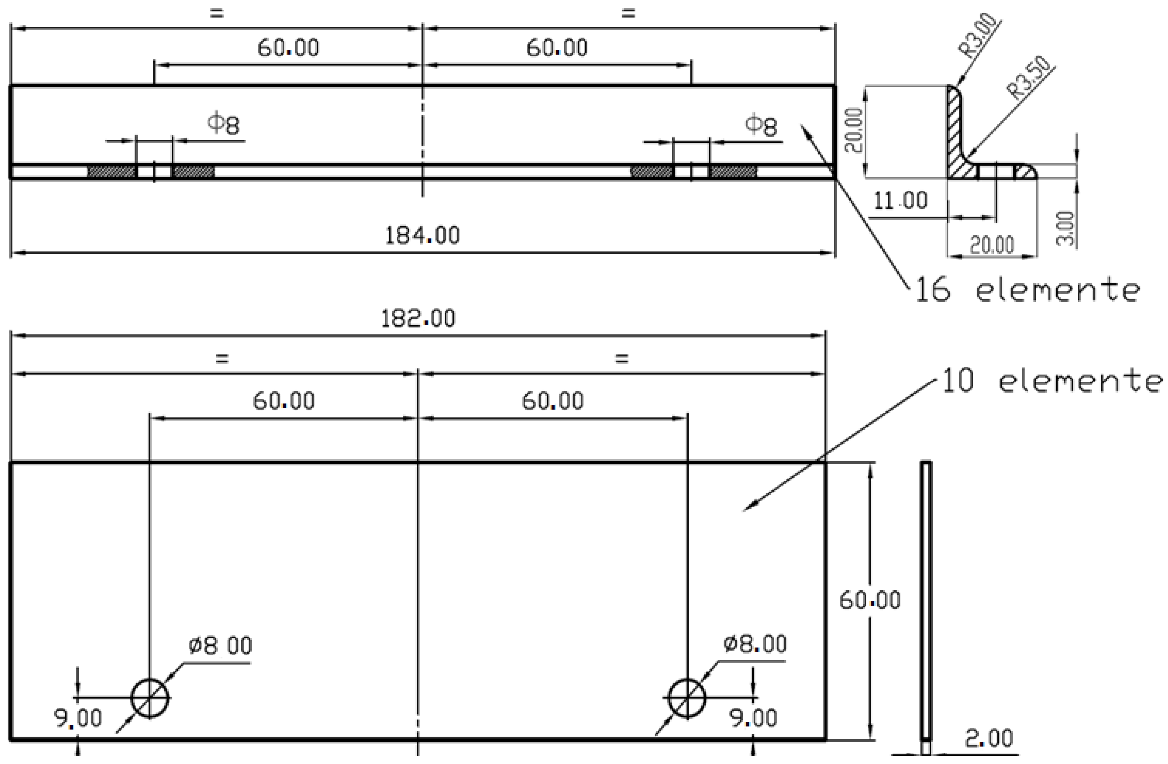
21], in order to analyze the wear of the flights, an experimental stand was designed, reproducing on a 1:4 scale the section of the rotary dryer body corresponding to the aggregate dispersion section (
Figure 1). It consists of a cylindrical vessel equipped with parallelepiped-shaped inner flights (the working surface is rectangular and flat—
Figure 2). The flights are usually made of carbon steel. In order to evaluate the wear behavior of various materials, the experiments involved the use of six types of steels (denoted by the acronyms S, C, D, E, F, and G—
Figure 3), with the chemical composition shown in
Table 1 and hardness values presented in
Table 2.
The choice of the materials from which the samples were to be made was based on the following considerations:
- -
It was considered that the steel commonly used for such industrial applications is S235;
- -
Steels that are similar in terms of purchase price were chosen in order to offer cost-effective solutions;
- -
The selected steels must have good weldability because the assembly procedure in the body of the dryer presupposes the performance of welding operations, among other things.
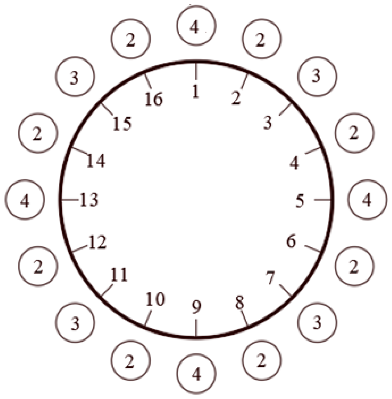
Inside the drum, dry mineral aggregate with a grain size of 4–8 mm was introduced, with a filling degree of 15% (7.75 kg of aggregate). The rotation of the drum was ensured by the motor associated with a turning machine. Samples were tested in two stages: in the first stage, samples of C, D, E, and F steels, and, in the second stage, samples of S and G steels, together with samples of C and D steels, reintroduced to complete and balance the drum, with the same thickness.
Thus, the aim was to simulate the movement of aggregate particles inside the dryer and to study the wear phenomena to which the flights are exposed as a result of contact (sliding and impact) with abrasive particles.
Abrasive wear and mass loss are two closely related concepts in the context of deterioration of materials subjected to wear processes [
5,
29]. Abrasive wear is, in fact, the process by which the surface of a material is damaged as a result of the action of abrasive particles moving or sliding on that surface. Mass loss, on the other hand, is the amount of material that is removed or damaged as a result of the abrasive wear process. There is a direct relationship between abrasive wear and mass loss because the amount of material lost from a surface is a measure of the degree of abrasive wear. The more severe the abrasive wear, the greater the mass loss will be. By measuring mass loss under different wear conditions, the performance and durability of different materials and treatments can be assessed, thus contributing to the development and improvement of wear-resistant materials. In conclusion, mass loss is a direct measure of abrasive wear, and it is used to quantify the degree of damage to a material as a result of the action of abrasive particles.
For this purpose, the wear of the steel samples (flights) from the research [
20,
21] was determined gravimetrically by weighing them at different time intervals.
Table 1.
Chemical composition of steel samples.
Table 1.
Chemical composition of steel samples.
| Try | Chemical Composition, % |
|---|
| C | Si | Mn | P | S | Cr | Mo | Ni | At | Co | Cu | Nb | Ti | V | W |
|---|
| C (AISI 4140 ASTM A29 [30]/42Cr4Mo2 EN 10083 [31]; rolled semi-finished product, thickness s = 4 mm) | 0.289 | 0.252 | 0.468 | 0.011 | 0.003 | 0.340 | 0.020 | 0.030 | 0.035 | 0.007 | 0.026 | 0.040 | 0.110 | 0.058 | 0.020 |
| D (AISI 4140 ASTM A29 [30]/42Cr4Mo2 EN 10083 [31]; rolled semi-finished product, thickness s = 3 mm) 4140 | 0.174 | 0.034 | 1.390 | 0.010 | 0.003 | 0.07 | 0.0017 | 0.06 | 0.021 | - | 0.23 | 0.0004 | 0.14 | 0.09 | - |
| E (S275 EN10025 [32]; laminated semi-finished product, thickness s = 2 mm) | 0.075 | 0.004 | 0.268 | 0.021 | 0.011 | 0.170 | 0.040 | 0.130 | - | 0.100 | - | - | 0.380 | 0.050 | 0.030 |
| F (S185 EN 10025 [32]; laminated semi-finished product, thickness s = 2 mm) | 0.051 | 0.005 | 0.300 | 0.018 | 0.013 | 0.200 | 0.060 | 0.270 | - | 0.340 | - | - | 0.220 | 0.110 | 0.010 |
| S (S235 EN 10025 [32]; rolled semi-finished products, thickness s = 4 mm *) | 0.1710 | 0.0320 | 1.370 | 0.0106 | 0.0032 | 0.0279 | 0.0017 | 0.0.0205 | - | - | - | 0.0005 | - | 0.0029 | - |
| G (S355 JR SR EN 10025 [32] laminated semi-finished product, thickness s = 4 mm *) | 0.090 | 0.040 | 0.760 | 0.014 | 0.011 | 0.130 | 0.040 | 0.140 | 0.015 | 0.100 | 0.100 | 0.010 | 0.050 | 0.100 | 0.010 |
Table 2.
Hardness value for the tested samples.
Table 2.
Hardness value for the tested samples.
Steel
Type | Hardness Value, HV | Hardness Mean Value, HV, before Testing | Hardness Mean Value, HV, after Testing |
|---|
| Sample 1 | Sample 2 | Sample 3 | Sample 4 |
|---|
| C | 145 | 141 | 146 | 148 | 145 | 160 |
| D | 172 | 184 | 175 | 180 | 178 | 204 |
| E | 127 | 122 | 126 | 125 | 125 | 151 |
| F | 140 | 137 | 137 | 139 | 138 | 178 |
| S | 147 | 149 | 147 | 148 | 148 | 183 |
| G | 155 | 154 | 159 | 157 | 156 | 210 |
The hardness tests were carried out according to the specifications of SR EN ISO 6507-1:2018—Metallic Materials [
33]: (1) Vickers hardness test, Part 1: Test method and SR EN ISO 6506-1:2015—Metallic Materials [
34]; (2) Brinell hardness test, Part 1: Test method using the Emcotest M4C 025 G3M durometer (Emcostest, Salzburg, Austria). The results of the tests (as an average of four values) are presented in
Table 2. Hardnesses were measured on the surface of the samples before and after the experimental tests. A pronounced hardening could be observed on the surface of sample G after testing.
Unlike the in situ operation of a rotary dryer, the tests were carried out in an accelerated mode with a constant main shaft speed of 16 revolutions per minute throughout the experiments.
2.2. Mass Loss Measurements
In the experiments, flight wear was evaluated based on the mass loss resulting from the erosive–abrasive action of the mineral aggregate particles. The values obtained by weighing the samples at the initial time and after 1, 3, 7, 11, 15, and 20 h of operation, respectively, are shown in
Table 3. For example, in
Figure 4, the real situation where wear can manifest unevenly on the surface of a flight is presented, with total degradation of the material over a limited extension portion.
Since the masses of the samples under investigation covered a relatively large range (especially due to the differences in the thickness of the semi-finished products from which the samples were extracted), a Kern EMB 1000-2 precision balance (Kern, Stuttgart, Germany) was used for weighing, with a weighing capacity of 1000 g and a reproducibility (weighing accuracy) of 0.01 g. For each trial and sample, two weighings were performed. Thus, the results in
Table 3 represent the average of two values. Weighings were verified, for samples weighing less than 250 g, using a KERN ALJ 250-4AM analytical balance (Kern, Stuttgart, Germany) that has a precision of 10
−4 g.
3. Results and Discussion
Based on the data in
Table 3, the least-squares method was applied to identify trends in the experimental data on attrition and mass loss. This makes it easier to define the evolution of mass loss in relation to influencing factors, allowing the estimation of future wear under different working conditions. The results of applying this method led to the determination of mass loss functions, defined as failure rate functions (
Table 4). These functions serve as the basis for determining the service life associated with each sample.
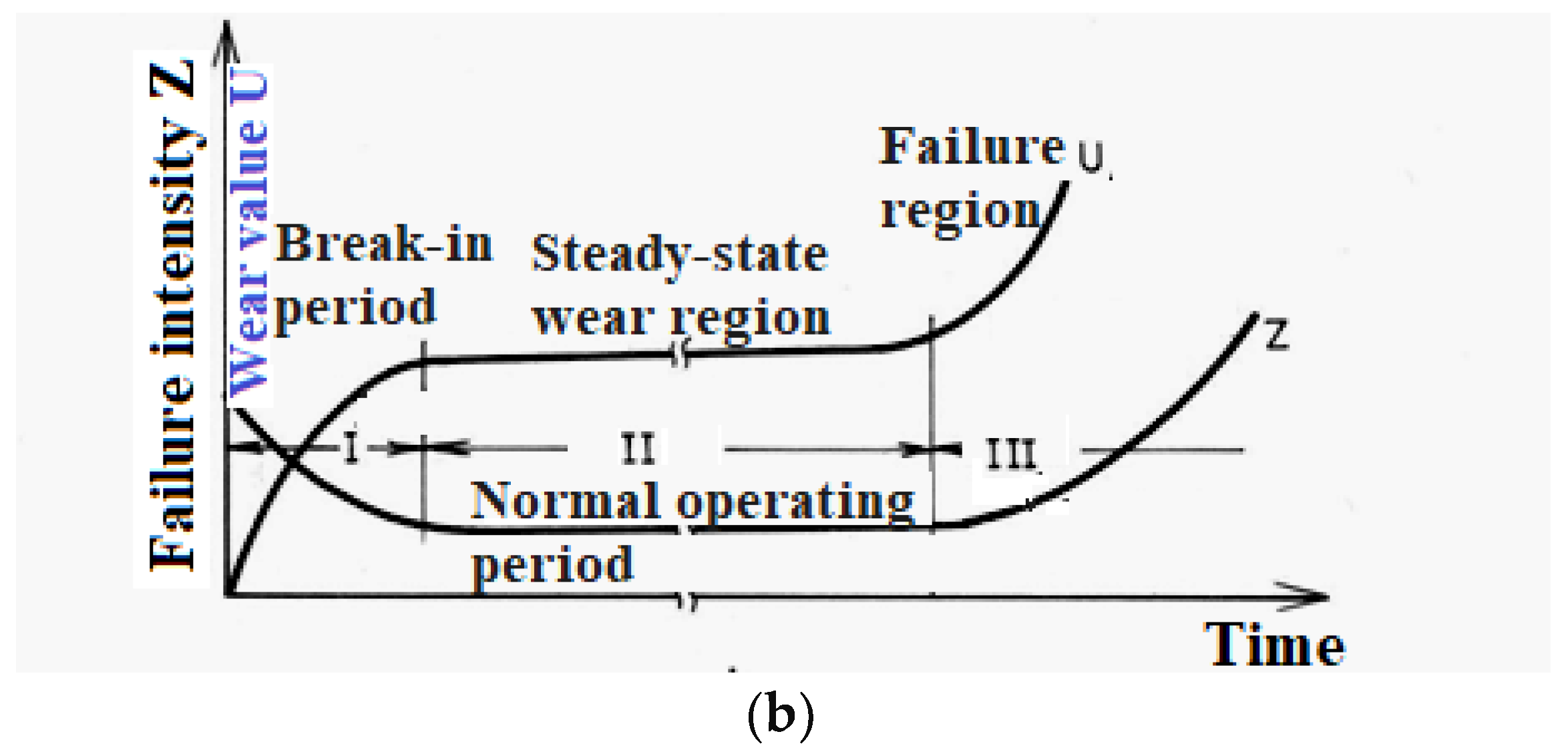
Table 4 also shows the failure rate functions corresponding to the six categories of steels: S, C, D, E, F, and G. These were derived by applying, in a similar way, the least-squares method For each sample and also for each category of steel, linear trends specific to the mechanical phenomena of chipping wear (see
Figure 5 [
35]) were represented. In order to highlight the accuracy of the results, the coefficient of determination corresponding to each function is presented in
Table 4.
The failure rate functions thus determined can then be used to determine the ultimate service life (tlim) for the flight-type components made of steel grades considered in the experimental tests.
In a first step, starting from the observation that the initial masses of the studied samples within each steel category are slightly different, and assuming that the surface area of the samples is the same, an average initial thickness of each flight category was determined based on the relationship:
where
is the average initial thickness of steel samples,
is the average initial mass of samples for each steel category,
is the steel density, and
S0 is the initial surface of the specimen. The mean initial thickness
s(0) was calculated by determining the simple arithmetic mean of the initial weights of the samples, values of which can be found in
Table 3.
The results of applying this algorithm are shown in
Table 5.
3.1. Determination of Operating Life in Relation to Mass Loss
Under the assumption that a limiting operating time, t
lim, corresponds to a complete mass loss, the failure rate function must satisfy the condition:
If it is assumed that, as stated above, the failure rate function follows a linear distribution in the form,
where
a and
b are the law parameters, identified in
Table 4 for each studied steel category, and
t is the service life.
In order to make an extrapolation that is not too long and does not distort the results, we determined the time elapsed until the loss of 2 g of the mass of each sample.
The equation for determining the limiting service life is:
Values of
, which were determined in number of operating hours for each category of steel tested, are shown in
Table 6.
As can be seen (
Table 6), the highest service life values were recorded for steel grades E and G. The mechanical characteristics—especially the yield strength [
36]—seem to strongly influence the abrasion resistance of low-alloy steels, a category to which the steels under investigation also belong. Steels E (R
p0.2 = 275 MPa) and G (R
p0.2 = 355 MPa) have the yield strength with the highest value, with the exception of AISI 4140, whose yield strength of 415 MPa is above the previously mentioned values. It should be noted, however, that AISI 4140 has much higher carbon contents than the other steels, which seems to negatively influence the wear behavior.
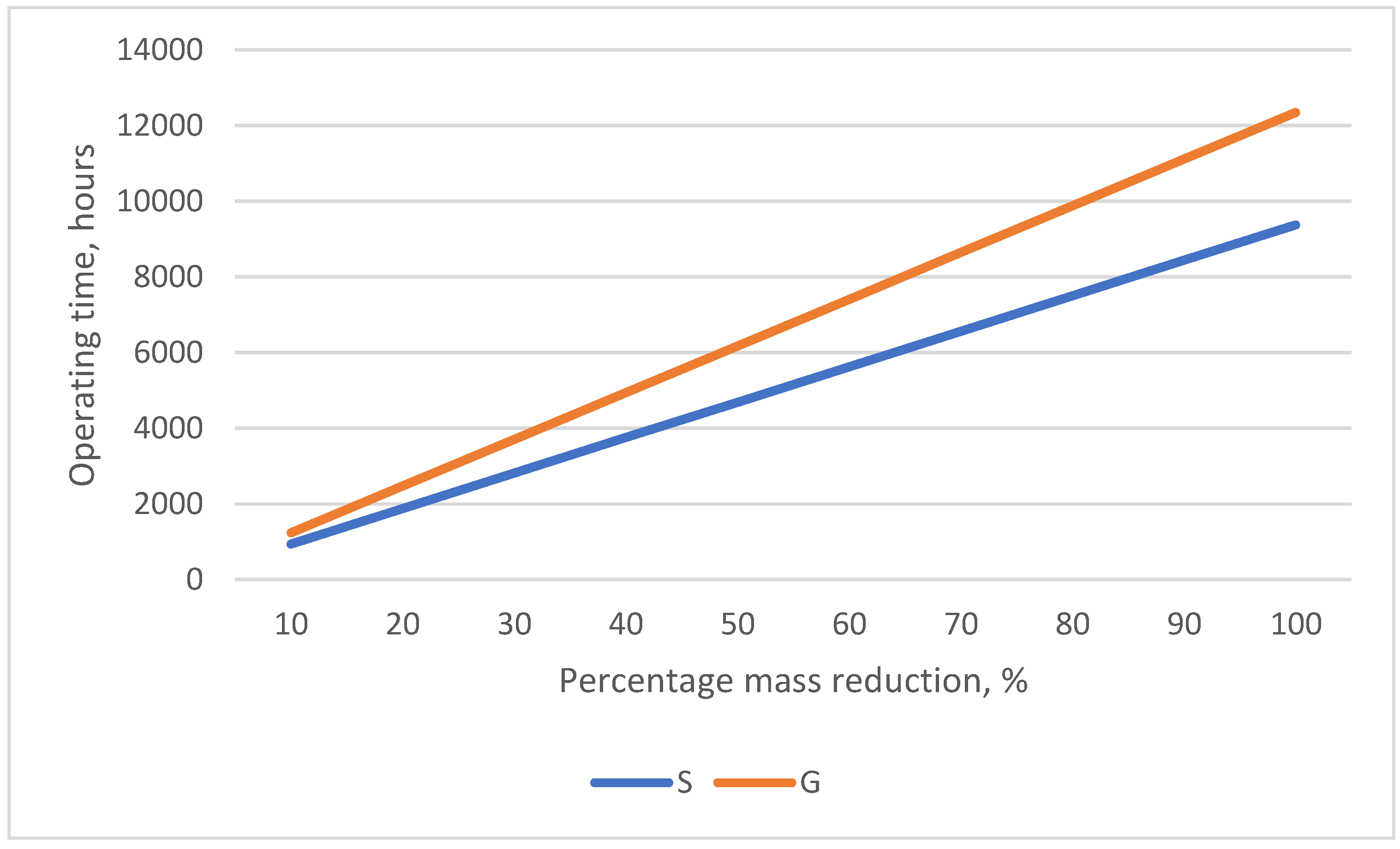
In order to make a comparison between the classes of steels, the lifetimes corresponding to the percentage reductions in mass for the interval 0–100% are shown in
Table 7 and represented graphically in
Figure 6. The data in
Table 7, including complete mass loss, are results of simulations. A complete loss of mass can be achieved on even 1% of the surface, for example, in the case of uneven wear, which can sometimes lead to the removal of equipment from use. The results of the simulations, which contain the complete loss of mass only for a certain part of the parts (equipment), contribute to the correct choice of the maintenance moments.
3.2. Determination of Operating Life in Relation to Mass Loss and Affected Area
In the evaluations presented in
Section 3.1, it was considered that the test specimens (flights) were affected uniformly over the entire working surface so abrasion wear was uniformly manifested. In practice, it is often found that some of the flights are unevenly affected over the surface by the erosive–abrasive action of the mineral aggregate particles. In this case, we see different mass losses—caused by different thickness losses—on certain areas of the flight surface, the extent of which is random. In this case, the operating time limit needs to be determined by reference not only to the mass reduction but also by considering the area of the surface affected by the intensive thickness reduction.
Starting from the Hrusciov and Babicev formula [
37], which expresses the relation between the depth of abrasion wear, the volume affected, and the contact surface area, it can be considered that, in the case of losing a part
of the initial mass of the sample—
, corresponding to a limited area representing a part
of the initial surface area
S0 where
—then the average reduction in thickness
over this area will be given by the relation:
where the parameters have the meanings mentioned above.
On the remaining surface, the average thickness reduction
will be given by the relation:
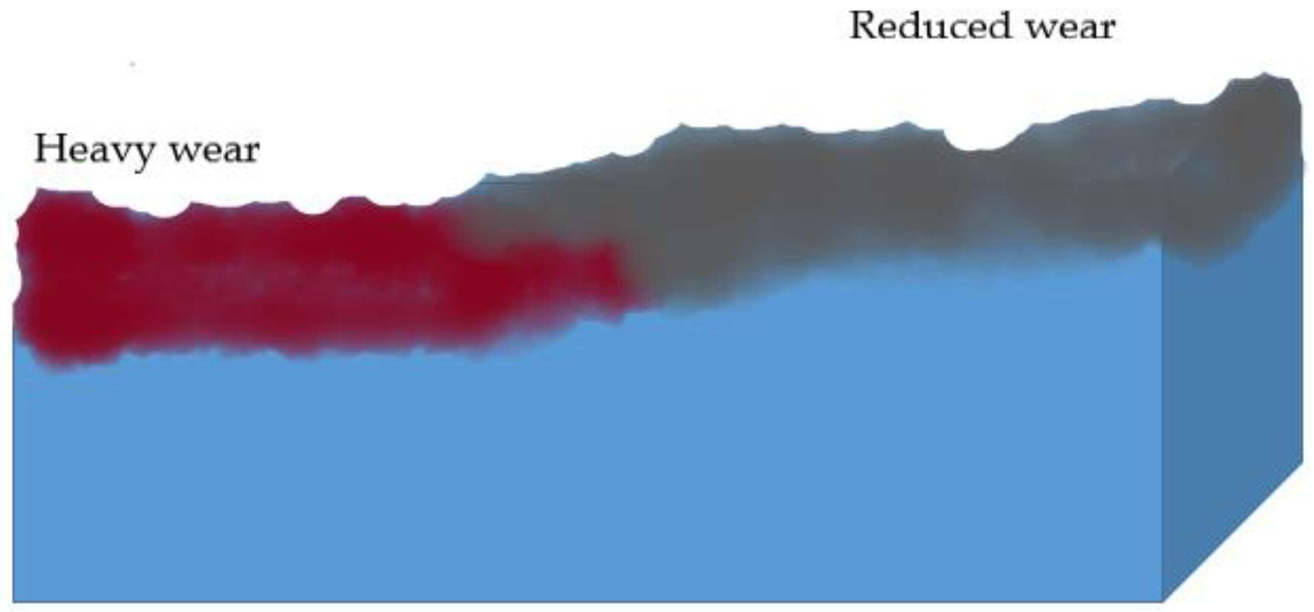
In this case, the wear of the specimen (flight) will be evaluated by taking into account the differential thickness reduction on the two affected areas. As an example, we considered a total mass loss equal to half of the initial mass of the specimen but with a differentiated distribution over two areas of the flight surface (
Figure 7).
Therefore, based on the above-described algorithm, surface 1 (red color in
Figure 7) has an area
S1 equal to
while surface 2 (gray color in
Figure 7) has the area
S2 equal to
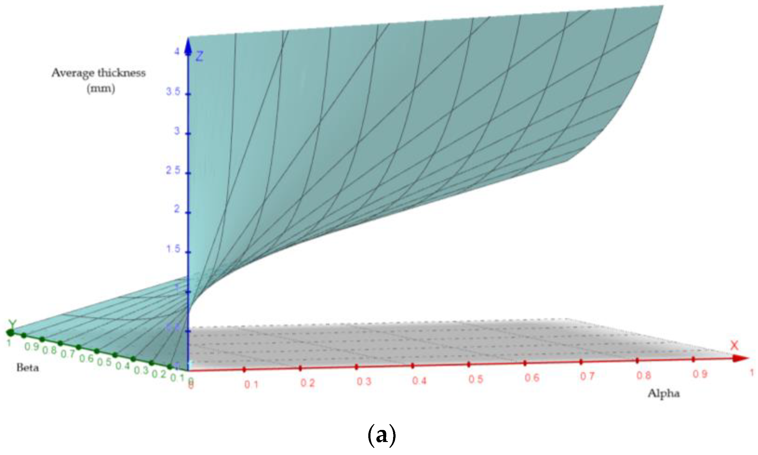
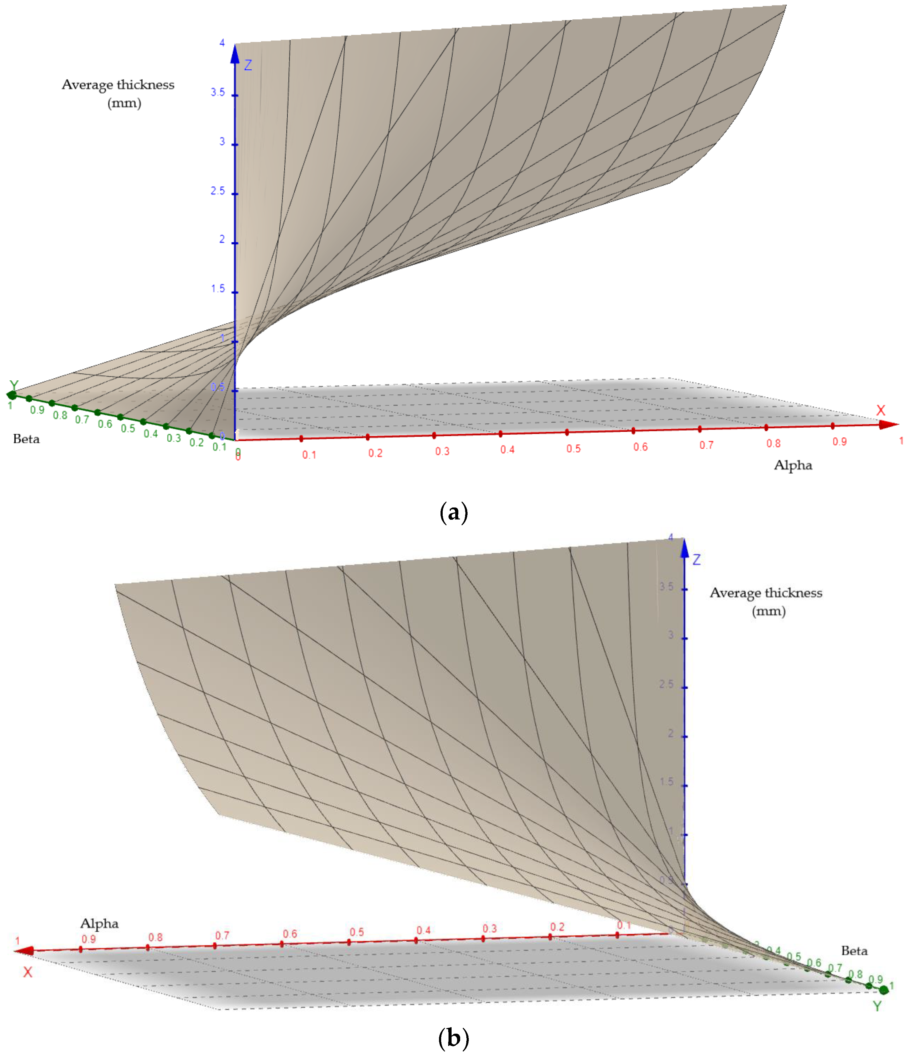
For the two categories of steels (G and S), the level surfaces describing the average flight thickness reduction under the circumstances described above are plotted in
Figure 8 and
Figure 9 based on data presented in
Table 8 and
Table 9.
In
Figure 8 and
Figure 9, the x-axis corresponds to the α variable, the y-axis corresponds to the β variable, and the z-axis corresponds to the average flight thickness reduction.
4. Conclusions
The use of the least-squares method in the analysis of experimental data can help to optimize technical phenomena in general and wear phenomena in particular.
The authors proposed an algorithm to evaluate the degree of wear (expressed as mass loss and thickness reduction) of the “flight”-type elements of the rotary dryers. The wear measure was further used to estimate the service life of the samples considered.
The function that helps to estimate the limit time can be applied by imposing a mass loss (expressed as a percentage) relative to the initial mass of the sample. For each category of steel under study, the function expressing the service life limit can be used to estimate the wear evolution regardless of the type of part examined. Under these conditions, the technique proposed by the authors can be a rapid tool for assessing the degree of wear or the remaining service life of industrial parts.
The procedure can also be applied in cases where the wear shows up differentially on the surface of the parts. In this case, a prior assessment of the extent of the surfaces with different degrees of wear must be carried out. As an example, the results of applying the method to G and S steels have been presented in the paper.
The results highlight the fact that the hardness—in a narrow range, 120 … 180 HV—does not essentially influence the wear behavior of the studied materials. It is not possible to establish a certain evolution of wear by reference to the hardness value. However, the mechanical characteristics—especially the yield strength [
36]—seem to strongly influence the abrasion resistance of low-alloy steels, a category including the steels investigated in the present work.
The purpose of the research was not to identify the steel with the best erosive–abrasive wear behavior, but to establish, based on a relatively large number of experimental results, a method for estimating the duration of operation of the flights of rotary cutters.
The methods proposed in this paper can be extended to any category of material or part provided that the failure rate function is first identified, possibly by laboratory experiment.

 ,
, 