Abstract
An ARM Cortex simulation system for collaborative welding robots is presented in this paper. The components of the ARM Cortex SoC for embedded robot control, an OpenGL ES with image rendering, and a 3D geometry engine OpenCasCade for modeling are integrated for the purposes of simulating system self-controllability and cost effectiveness. This simulation of a collaborative welding robot achieved convenience while meeting the performance requirements; meanwhile, the auxiliary design was able to mark the trajectory of the robot’s end effector and reveal the collaborative robot’s inverse kinematic parameters, namely the position and Euler angle. An ARM Linux X11 Window environment that was set to create a 3D simulation rendering algorithm was built simultaneously. Then, the STEP model of the robot was loaded by using the OpenCasCade functionality. After that, the robot model and complex spline surface could be visualized by using the Qt QGLWidget. Finally, the correctness of the kinematic algorithm was verified by conducting simulations and analyzing the robot’s kinematics through the simulation results, which could verify the expected design and provide a set of fundamental samples for the robot trajectory industry regarding welding applications.
1. Introduction
Since 2020, with the rapid and significant changes that have occurred in China’s new energy automobile industry, collaborative welding robots have been gradually applied in the welding field. The new high-end automobile manufacturing industry has put forward specific requirements for the simulation of collaborative robots [1]. However, most control systems currently on the market for rendering 3D robot models and planning their trajectories are based on the x86 Celeron [2]. These systems have closed hardware and use graphical driver sources to render 3D robots or other models, although their methods provide sufficient model data accuracy. But this leads to pointless equipment costs related to image rendering. Therefore, the moderate demand for simulation rendering software and ARM Cortex 3D simulations of robot welding is considered here. It is of great significance to create a cortex-based collaborative robot simulation method. The above module guarantees the feasibility of the trajectory planning algorithm for collaborative robots [3]. The simulation results can be used to verify our early design objectives and provide a feasible scheme for planning the trajectory of the welding applications of collaborative robots [4].
This design of the hardware module of the system integrates an embedded control chip SoC based on the ARM architecture, the 3D model image rendering standard OpenGL ES 3.0+, the Linux operating system, and OpenCasCade 7.5.0. The simulation system should configure the hardware device driver based on the ARM architecture and the Linux kernel through the Device Tree interface. This method ensures that the X11 form attribute interacts with Aspect_Window through the QGLWidget. Then, the collaborative welding robot 3D model [5] could be constructed by making use of FreeCAD or SolidWorks to create the model, and then deriving the robot’s mathematical equations and performing a kinematic analysis. The OCCT is used to parse the STEP files corresponding to the robot.
Lastly, the model is rendered by exploiting the QGLWidget. Our experiment verifies the feasibility of using the universal SoC OpenGL ES 3.0+ hardware instruction set, a Linux MESA graphic driver, and OCCT geometry algorithms within the ARM xFce4 4.18.0 desktop environment [6], which serves as a foundation for discrete robot trajectory planning and design.
2. ARM 3D Model Simulation Design
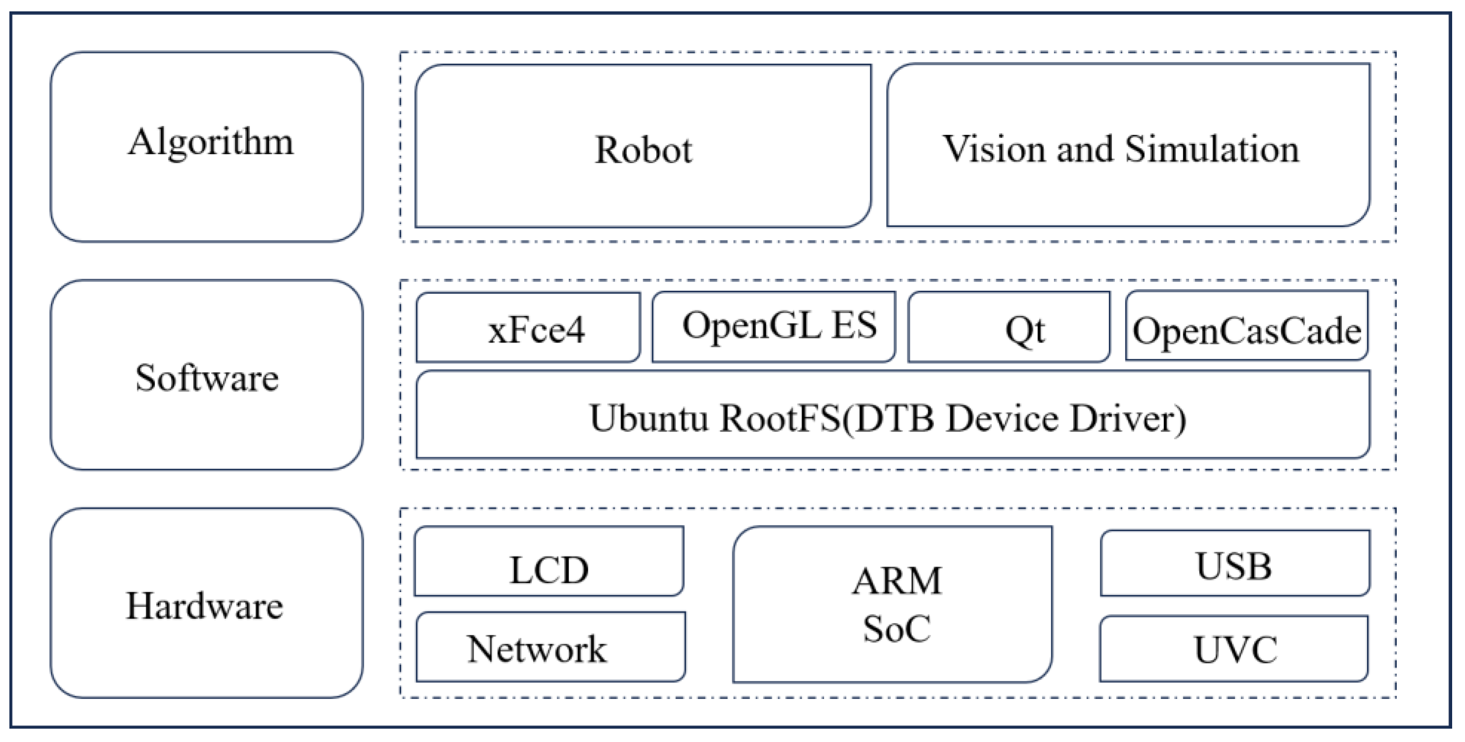
This design depends on the ARM Cortex and is constructed to satisfy the various demands of collaborative robots in the field of welding simulation. The crucial ingredients consist of the following elements: the ARM Cortex SoC, the NIC Card module, the ARM(Ubuntu) rootfs module, the OpenGL ES 3.0+, the OpenCasCade 3D algorithm module, and the AUBO-i10 robot welding kinematics algorithm. It provides high-accuracy 3D model rendering and real-time float point data numerical computation. Figure 1 shows a diagram of the ARM SoC embedded simulation’s design.
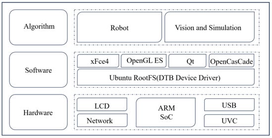
Figure 1.
Diagram of the embedded simulation system’s design.
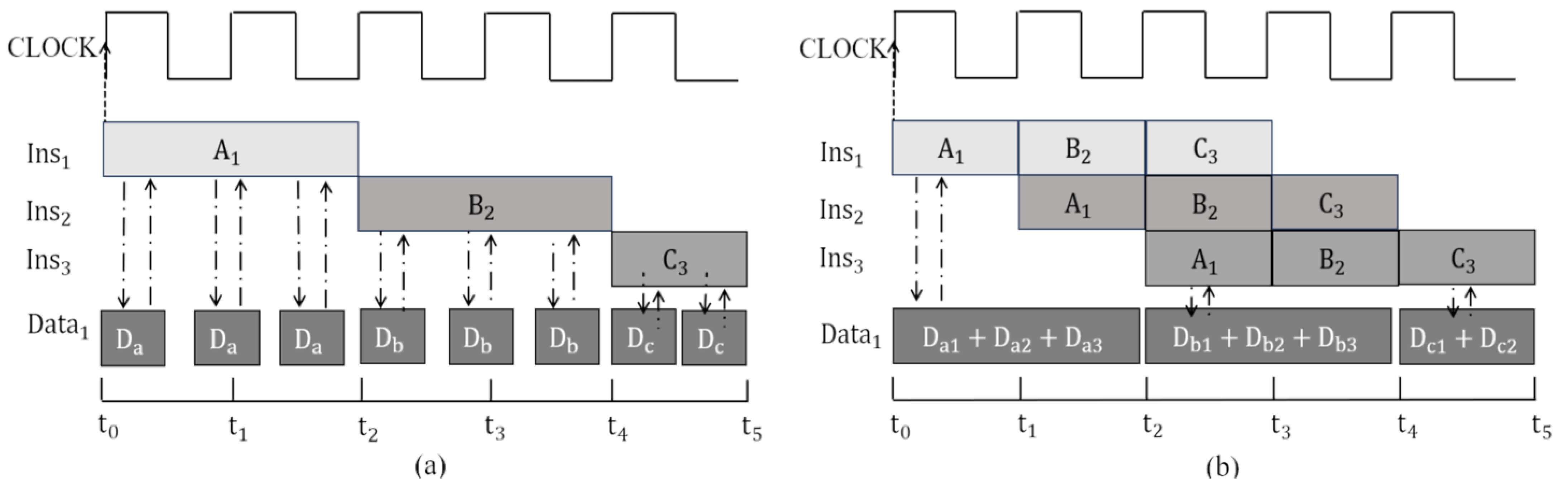
The execution phase when the ARM’s serial instructions are executed within a memory read-and-write clock cycle is shown in Figure 2a. Each pixel is assigned a single and standalone thread, and hundreds of different threads can be run to render an image. However, compared to the principle of multithreaded parallel computing with pipeline instructions, hardware utilization can be achieved through rational scheduling, as shown in Figure 2b, which is a clever approach of balancing hardware costs and execution efficiency in SIMD execution [7]. Thanks to ARM’s excellent cache design, the MOP can provide more instructions and data for each clock when pipeline instructions are used. These methods ensure the effective numerical computation of ARM 3D rendering and a balance between hardware and software efficiency.
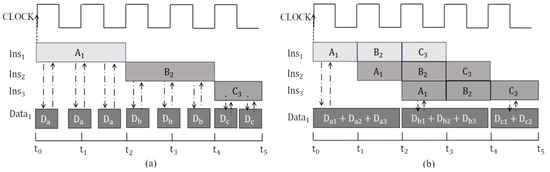
Figure 2.
Diagram of execution principle: (a) serial instruction; (b) pipeline instruction.
(1) ARM Module: Check and configure the basic built-in OpenGL ES hardware interface with entry level (Samsung, city of Seoul, Republic of Korea), or industrial level (NVIDIA, City of Santa Clara, the USA and Phytium, City of Tianjin, China). Receive and send data from the NIC, which constructs basic channels connecting the rootfs ARM version with NFS, and load the Linux kernel. Then, configure the screen register to display the xFce4 desktop and compile the Qt widget for the subsequent 3D model rendering.
(2) NIC Module: This supports the interaction between MAC and PHY data to assess the internal flash to adjust to different types of protocols. It can be an important bridge between the kernel and the root file, or between a real robot and a computer simulation.
(3) ARM RootFS: This module configures the NIC settings and library sources, which load within the desktop window xFce4 which is dependent on the X11, and provides a variety of device–driver interfaces to the user. Eventually, a complete set of functions will be constructed to customize and tailor the operating system’s library and applications.
(4) OpenGL ES Module: A criterion that facilitates the real-time rendering of 3D simulation scenes for AUBO-i10 robots involved in welding by supplying an interface on which to render the 3D model’s topology and texture.
(5) The OCCT geometry module is designed to model data and create the algorithm, application framework, visualization and coordinate sets. Each module consists of one or more geometry algorithms, providing a platform that developers can use to build robot models and complete simulation work.
(6) Collaborative Robot Module: The integrated joint design of a servo motor greatly simplifies the complicated spherical wrist joint kinematic equations and provides a solution.
The universal design of embedded systems encompasses the generic industrial ARM SoC system, the customization and compilation of OCCT under ARM, and the transformation of QGLWidget into an interface for the rendering of collaborative welding robots. By building the above key modules and integrating them seamlessly into the trajectory simulation application, the spline trajectory calculation tasks can be carried out by any type of robot operating under this combination of software and hardware.
2.1. ARM SoC
The hardware module can be constructed using OpenGL ES and OCCT, as shown in Figure 3a,b. It has a Cortex multiprocessor as its core that supports ARMv8.2 multi-stage pipeline instruction and has a corresponding built-in OpenGL ES section making it suitable for graphic modeling and complex spline rendering. In the MUL and IMUL phases, the processor provides multiple levels of cache, and an external clock meets the calculation requirements. The three key steps in OpenGL ES 3.0+, including the rendering vertex, mesh, and fragmentation shader, provide the underlying hardware that can be used to explore the simulation of OCCT on X11.
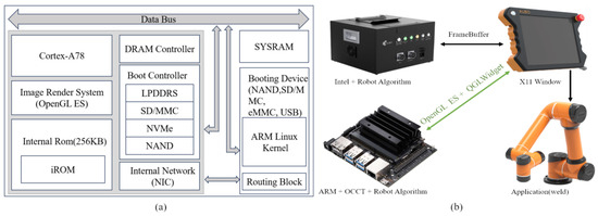
Figure 3.
Diagram of hardware: (a) ARM module; (b) robot controller.
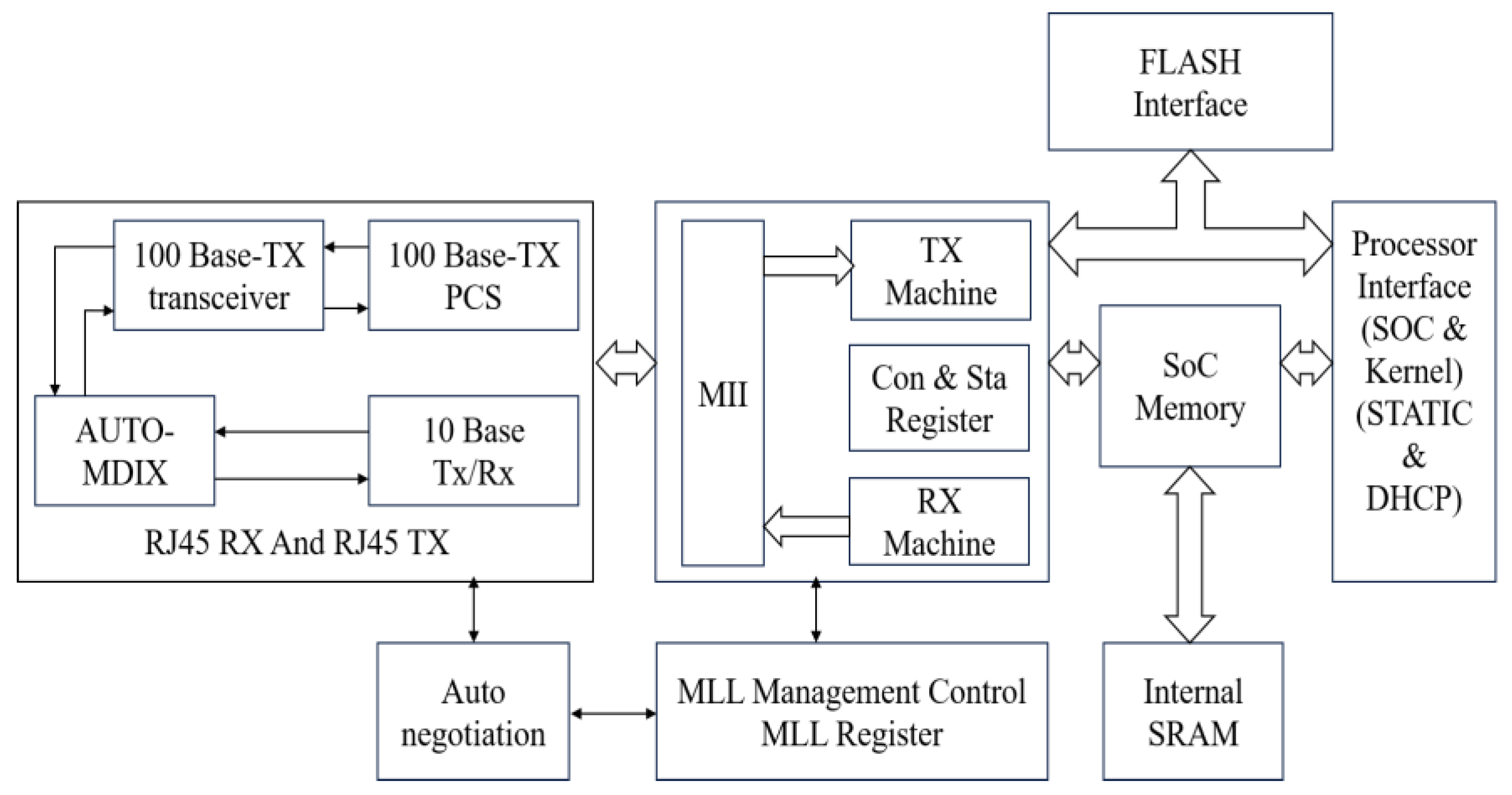
2.2. NIC Module
Since the MII protocol required an Ethernet controller that was configured with a universal network protocol for stable communication with a various ARM processor, the externally connected devices were allocated to exclusive channels with an 8-bit or 16-bit bandwidth. Furthermore, PCIE NIC supports active power management, error reporting, end-to-end reliable transmission, and the PCIE hot plug mechanism. So, NIC can be seen as an important bridge between the kernel and Ubuntu rootfs, or between the real robot and the simulation software. Figure 4 shows how the NIC works in principle.
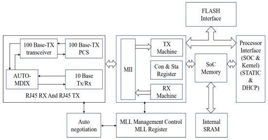
Figure 4.
Network Module.
2.3. ARM Ubuntu RootFS
The rootfs is an essential section of the simulation system after kernel startup, as shown in Figure 5a,b. Some parts of the startup scripts and initialization will be executed by the bootloader, which has a set IP and mount type before it is mounted. After that, the device driver and settings interface will be mapped into the root file system.
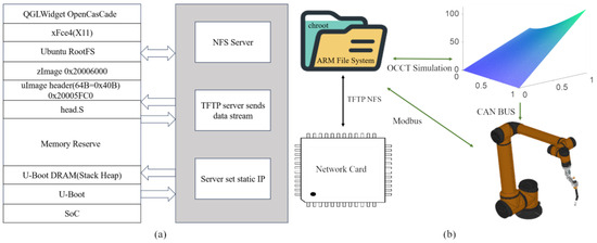
Figure 5.
Diagram of file system: (a) rootfs and NFS module; (b) Robot communication.
Please note, the file type of uImage that has a 64-byte header containing auxiliary information such as checksums and kernel entry address. In this article, the rootfs is mounted via the Network File System protocol, allowing users to configure different versions of the Ubuntu library source as needed.
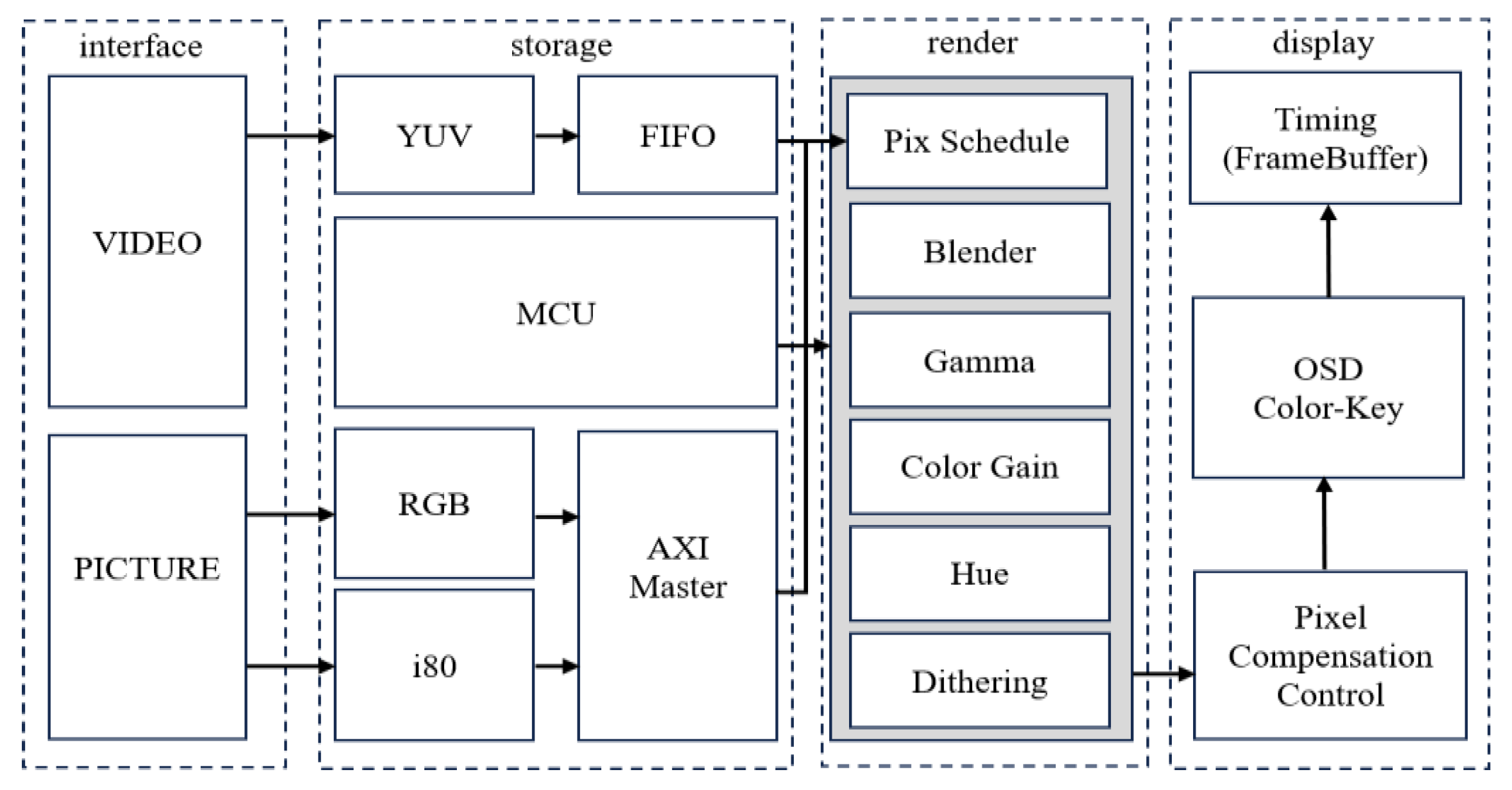
2.4. OpenGL ES Module
Major manufacturers of equipment have embraced the OpenGL ES 3.0+ criteria. The corresponding library offers packages that can be divided into various components, such as primitives’ data, framebuffer display, and the Rasterize process interface. Consequently, OpenGL ES has risen to prominence as the leading criterion for embedded 3D graphics rendering. From a logical standpoint, a composite image displayed on an LCD is termed a frame, as shown in Figure 6. Within the internal flash of an SoC, there is a storage interface that is called the FrameBuffer.
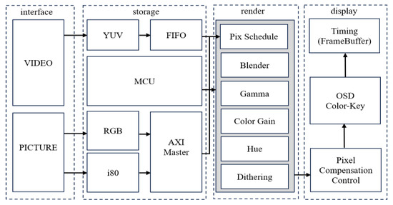
Figure 6.
Diagram of OpenGL ES processing.
The spline surface’s smallest component is the triangular mesh. Through the computation of these meshes on the matrix corresponding to a pixel in the image section of the LCD screen (FrameBuffer) [8], diverse fragments can be displayed on the screen. Given that the Shader procedure is depicted in the figure, altering the RGB ratios in a 24-bit or 32-bit data array can modify the color of the image, creating a blend of light and shadow that integrates the Z-Buffer 3D perspective. Ultimately, the aforementioned methods will yield a single image frame.
2.5. OCCT Geometry Algorithm
OCCT provides a variety of APIs for reading and parsing the robot STEP model about 3D models. However, it is important to note the fact that the coordinate directions stored within the STEP files have different orientations compared to those assembled by Parasolid 32.0 but using OCCT the right-hand rule to parse [9]. In particular, the coordinates of models generated by SolidWorks are significantly different from those generated by FreeCAD 0.19.
In addition to OCCT, there are other available solutions like Gazebo 11 and MuJoCo 3.1.0. Compared to these excellent software options, OCCT not only offers users a better modeling method, named NURBS but can also be tailored to meet the requirements of ARM Linux compatibility. It should be noted that using OCCT rendering under ARM SoC must support OpenGL ES 3.0+ and the X11 Window Protocol.
Given the aforementioned issues, it is necessary to use the mechanical modeling software FreeCAD 0.19 to calibrate the STEP model file of the coordinates. The internal third-party Part Module plays a crucial role with its function “Make Compound”, which provides adjustments to the rotation axis and angle based on the STEP file’s coordinate parameters. The core modules and third-party dependency library are shown in Table 1.

Table 1.
OpenCasCade dependency and functionality.
2.6. Inverse Kinematics Algorithm Optimization
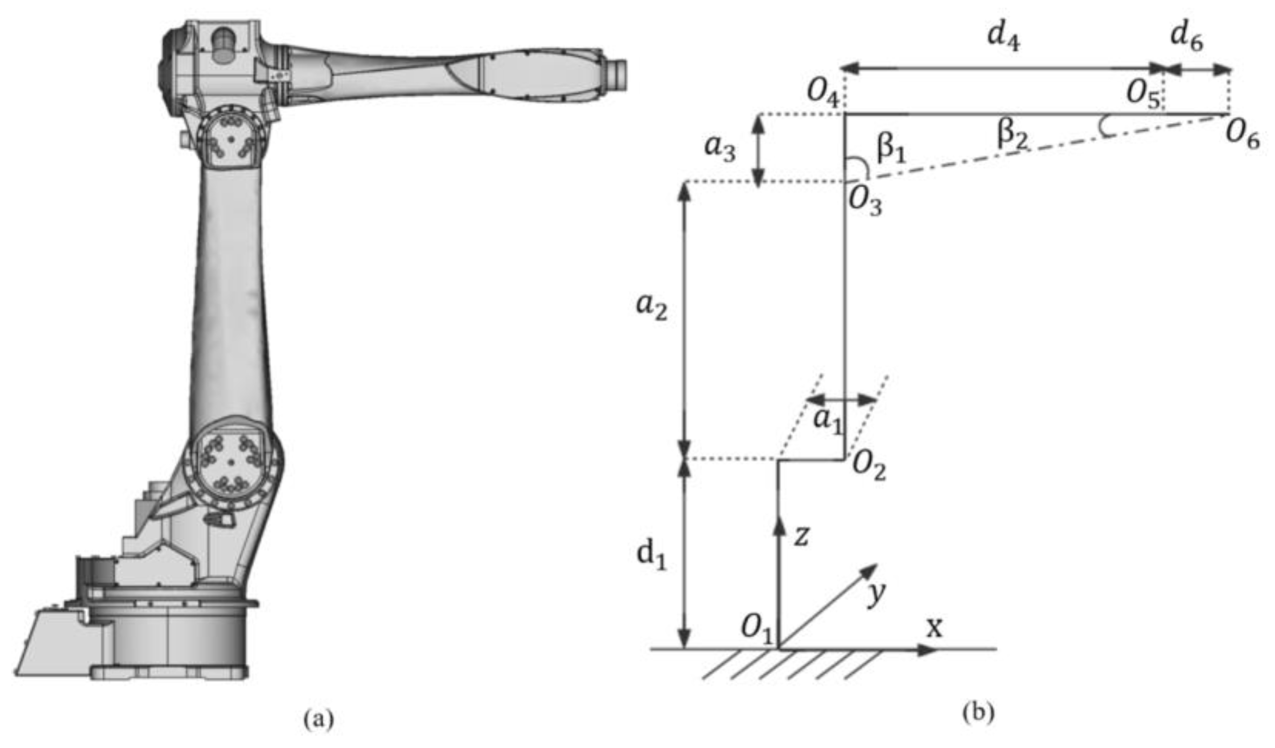
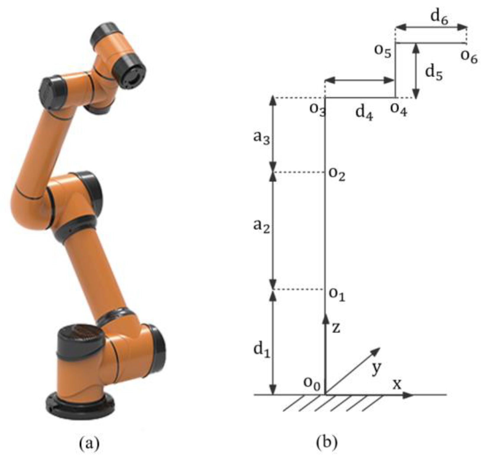
EverRobot is equipped with an independent spherical wrist, as shown in Figure 7a,b. It is important to note that the spherical wrist joint serves as a critical and independent mechanical design module primarily used for determining the end effector’s orientation. The inverse kinematics of the robot can be solved by transforming them from the endpoint back towards the center of the wrist, using the position and pose separation method, thus avoiding the homogeneous matrix inverse operation while efficiently obtaining the solution of the robot’s inverse kinematics.
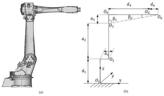
Figure 7.
EverRobot: (a) mechanical structure; (b) DH reference.
Due to the RH-20 robot’s mechanical structure design, the wrist point can be derived from setting the last joint offset. Both the position and orientation of the wrist can be controlled by the first three joints and the last three joints. However, the integrated joint design of the collaborative welding robot AUBO-i10 greatly simplified the complexity of the kinematics calculations. Therefore, choosing this type of robot for welding research is an excellent decision [10].
3. Modeling of Parametric Constraint and Collaborative Robots
3.1. Trajectory Planning for Collaborative Robots Welding
The constraint algorithm may set a value for the tolerance to solve surface intersections, as shown in Figure 8a. In comparison to traditional vision and algorithms in 2D and 3D, high-performance equipment must be adapted to handle edge detection [11]. In particular, most machine vision libraries are invoked in image binarization and the least squares method to compress image matrix information.
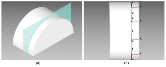
Figure 8.
Spline Trajectory: (a) intersection of two surfaces; (b) discrete trajectory on surface.
Similar challenges arose when the Point Cloud Library was introduced into image detection and three-dimensional modeling. While 3D structured light [12] provides extremely high precision in object detection to within millimeters, the Poisson Surface Reconstruction becomes a vital step towards achieving an indicator gradient vector by which the contoured surface can be reconstructed.
Therefore, utilizing spline surface interpolation and Gaussian–Legendre quadrature to generate a discrete trajectory [13] is a reasonable approach for welding, as shown in Figure 8b. Even transparent objects can be simulated better by parametric equations when compared to machine vision algorithms.
3.2. Kinematics Systems for Collaborative Robots Welding
It should be noted that comparing the parameters shown in Table 2 with those in Table 3 reveals the errors of deflection angle in the kinematic calculation caused by the motor size bias; hence, must be taken into account in inverse kinematics.
Table 2.
EverRobot DH parameters.
Table 3.
AUBO DH parameters.
In summary, designing integrated joints for collaborative robots greatly simplifies the kinematics calculation process and improves the efficiency of nonlinear equations, as shown in Figure 9a. Additionally, due to improvements made to the harmonic reducer and Servo Motor through mass production, now there is a price advantage but equal accuracy levels when using AUBO-i10 for welding purposes.
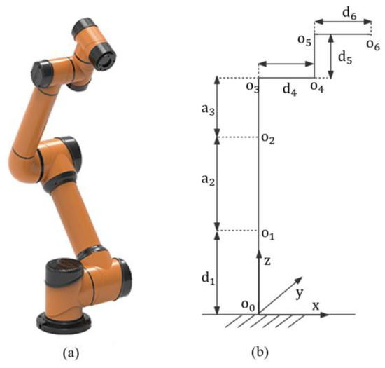
Figure 9.
AUBO-i10 robot: (a) mechanical structure; (b) DH reference.
4. Built ARM Linux Simulation Environment
4.1. Robot Model Rendering
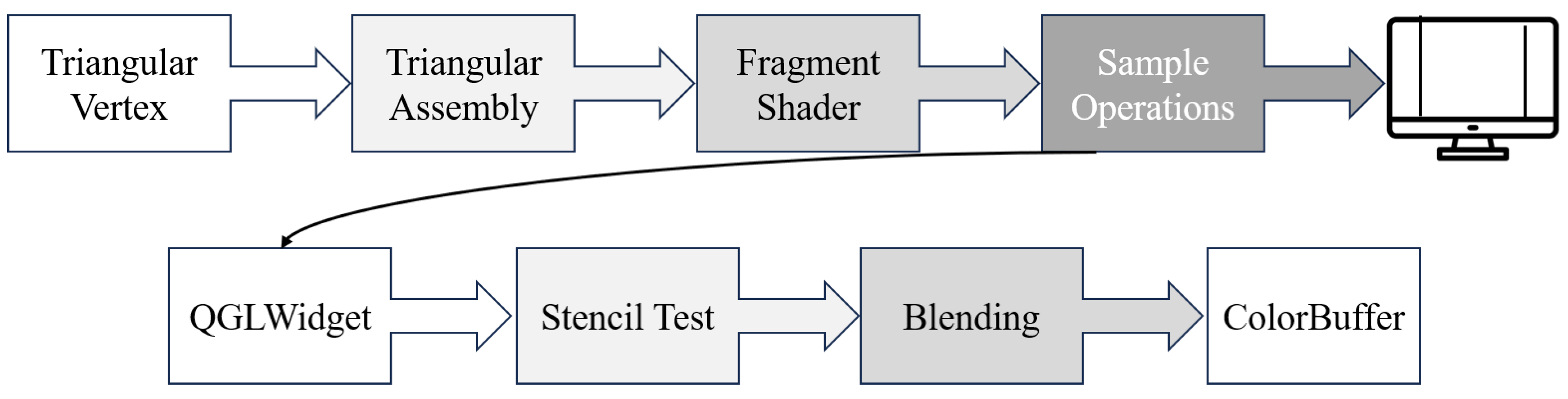
The rapid advancement of ARM graphics processors and their corresponding Shader algorithm criteria (OpenGL ES) has enabled complex geometry processing on industry manufacturer devices. This is achieved by translating function calls into hardware commands that can be delivered to the SoC graphics module. Not only does this provide a framework for rendering models, but it also enhances our understanding of how graphics drivers work. The study of vertex and fragment pipelines and the rasterized Shader algorithm based on OpenGL ES 3.0+ holds much practical significance [14]. Figure 10 shows the working principle of image rasterization.
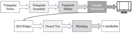
Figure 10.
Diagram of rasterization flow.
By leveraging the functionalities of ARM image processors, the rendering technique scheme incorporates QGLWidget 5.15.0 and OpenCasCade 7.5.0 under the ARM Cortex. It is undeniable that the 3D STEP model of collaborative welding robots can be rendered on screen using this approach. Via setting the axial angle with robotic linkage and adjusting the value simultaneously, the linkage can be multiplied like a homogeneous matrix, resulting in observable robotic joint movements.
When template testing and depth testing are combined in OpenGL ES 3.0+, the rasterization shaders shown in the above diagram simplify the rendering processes that were supposed to be repeated many times. For example, drawing shadows at intersections of composite geometric primitives, rendering textures and topology shapes, or handling highlights can all be achieved simply by mapping property. This approach fully utilizes both hardware resources and software drivers [15,16,17,18].
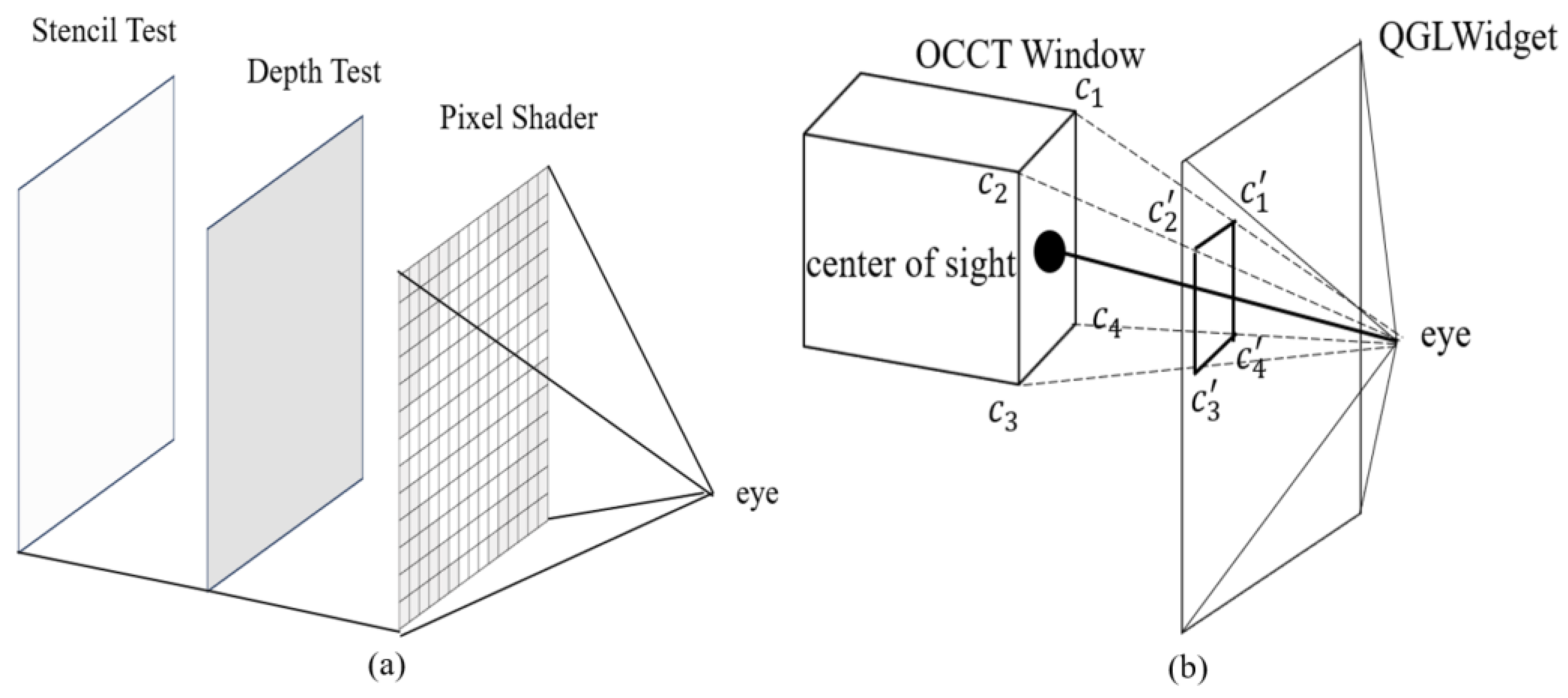
Understanding the stencil buffers and pivotal steps that map window properties into the model is crucial in this 3D modeling experiment which compiles both Qt source code and OCCT under ARM with OpenGL Stencil Buffers [19]. Additionally, as shown in Figure 11b, it involves converting the window’s Aspect_Window properties into QGLWidget data while accessing components of OCCT and Ubuntu or xFce4 X11’s attributes through a unique identifier, because the underlying window’s original attributes interact with the Qt through the X11 manager function winId [20]. Through the above analysis, a substantial groundwork is established for 3D model rendering and NURBS planning based on ARM SoC.
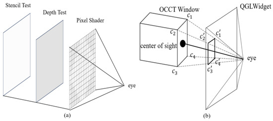
Figure 11.
Model rendering: (a) stencil test; (b) image mapping.
Finally, the Graphic3d_RenderingParams class has been expanded with the AdaptiveScreenSampling option [21]. This enhancement utilizes the MSAA and Laplace equations in the OCCT to adjust the ambient light in a specific direction, as shown in Figure 12a. The built-in Laplace equation of the geometry engine separates the variable r and the angles θ and φ, forming a gradient vector in a specific direction. This allows for continuous changes in the ambient light to be added from a specific perspective, as shown in Figure 12b. The effect of 3D objects and observers in the actual environment can be simulated using this approach.
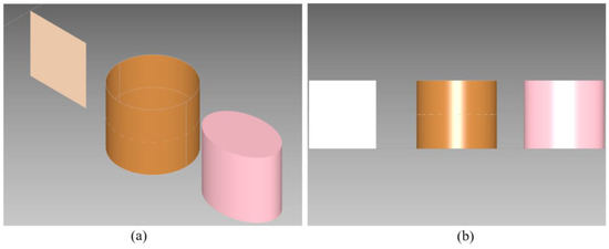
Figure 12.
Ray Tracing: (a) empty light; (b) directed light.
4.2. Rendering and Kinematics Calculation Validation
The robot STEP 3D model file can be accessed by using OCCT’s auxiliary STEPControl_Reader class, which reads properties such as coordinate, position, angle, texture, color, etc. The TDF_Label class is utilized to store unique identifiers that represent mechanical assembly parts. Additionally, translating Aspect_Window properties into QGLWidget is also a crucial step. Utilizing Qt model/view programming can assist users in quickly constructing the functionalities and operations of a model under ARM Linux. Taking full advantage of the ARM command set in branch prediction is key to optimizing Shader pipelines and processing complex 3D models.
Figure 13a,b demonstrates that 3D modeling supports texture mapping to simulate the real model. Based on these principles, collaborative robot manipulator in real environments can be completely simulated at a later stage.
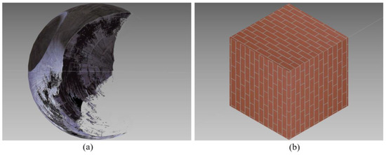
Figure 13.
Diagram of 3D modeling texture mapping: (a) spherical texture; (b) cubic texture.
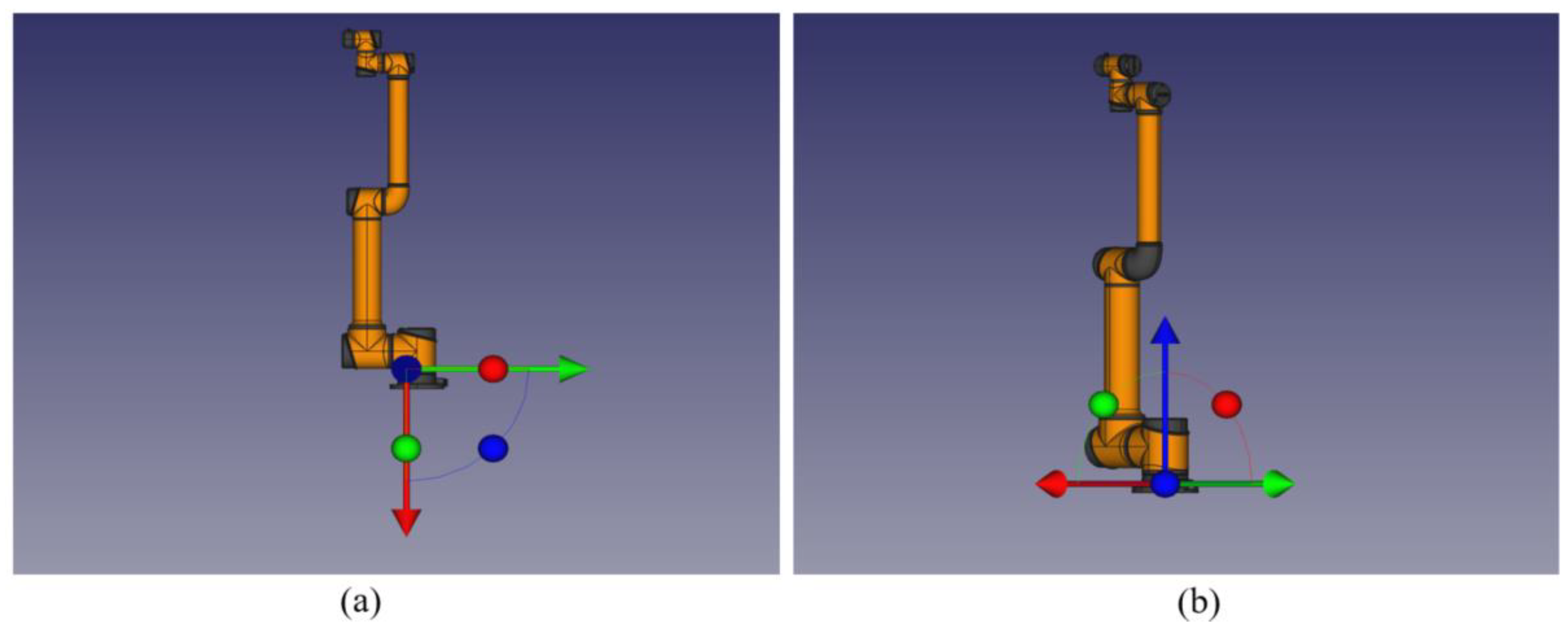
The coordinate system used by ParaSolid 32.0 differs significantly from the OpenCasCade 7.5.0 reference coordinate system that is used in this article, as shown in Figure 14a,b.
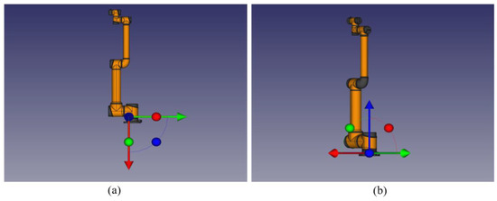
Figure 14.
Geometry engine coordinates: (a) ParaSolid coordinates; (b) OpenCasCade coordinates.
Ultimately, a full view of the robot STEP model can be achieved by applying the OCCT Aspect_Window and QGLWidget OpenGL modules. The sample could enable simulation welding applications to be created for new energy vehicle manufacturing techniques by configuring robot link axis angles derived from STEP parameters and utilizing gp_Trsf transformation’s function SetRotation with gp_Ax1 and the axis angles.
The robot model, as shown in Figure 15a, and the end-effector, as shown in Figure 15b, generated by the geometry engine are depicted clearly.
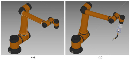
Figure 15.
AUBO robot assembly: (a) isometric projection; (b) end-effector of welding.
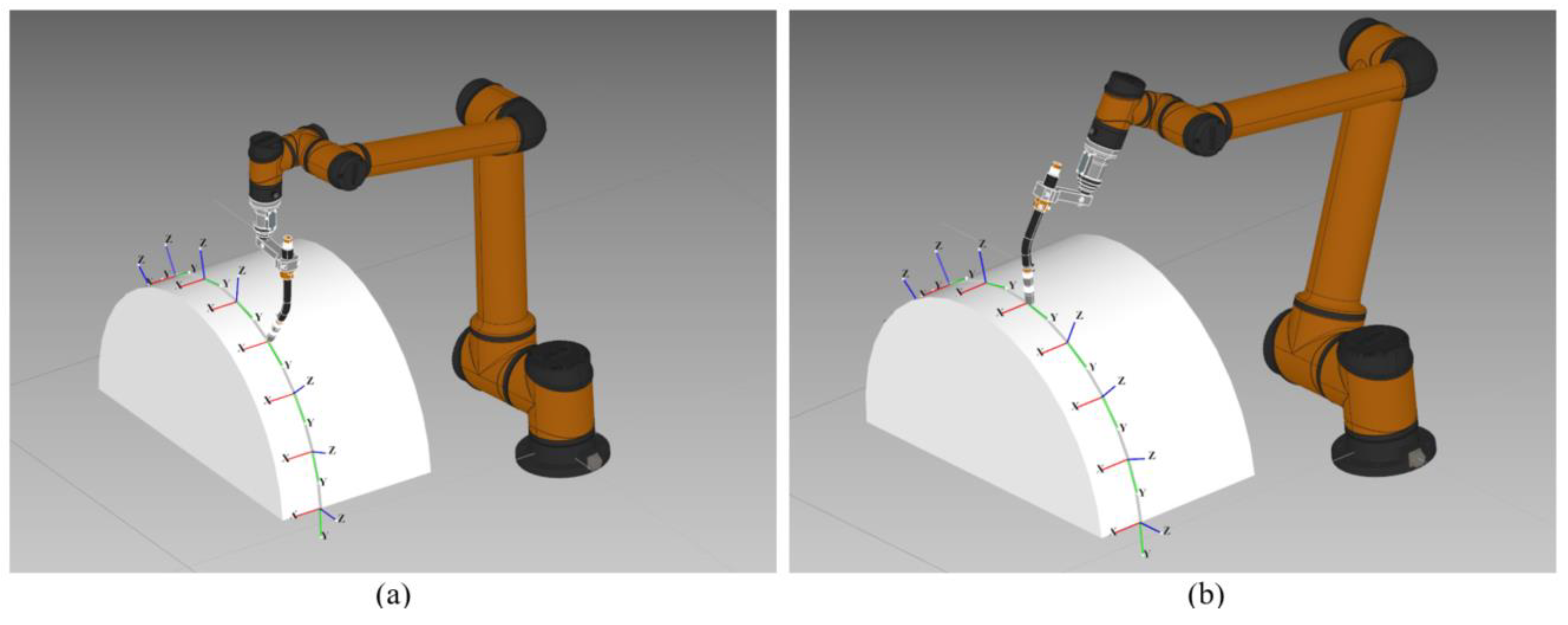
As is depicted in Figure 16a and referenced in the AUBO-i10 product manual for setting linkage parameters (−0.000172, −7.291862, 85.694718, 5.596727, 95.999982, −0.000458), the collaborative robot coordinates of the effector tool point are (−176.319, 267.499, 975.598). The result in Figure 16b can be verified by referring to the inverse kinematics solution and validating the STEP model’s coordinates calibration.

Figure 16.
Robot welding simulation: (a) first waypoint; (b) second waypoint.
By utilizing GeomAbs_Cylinder and GeomAdaptor_Surface on the topology surface, the normal vector can be derived from two different tangent vectors’ cross-product at a specified waypoint. The various discrete waypoints obtained from the surface can be calculated by using the same approach. It is important to note that, during the simulation process, there may be a significant angle reversal when calculating the normal vector at certain boundary points. The outcome is illustrated in Figure 16b, demonstrating a smooth displacement change on the surface in all directions.
The direction of the normal vector at each point could be utilized to determine the Euler angles (R, P, Y) that express the end-effector orientation through two-step rotations by referencing the OpenCasCade 7.5.0 window graphics scene default coordinate. Simulated discrete trajectory curves and kinematic data then can be generated for the robots based on these key parameters.
After equidistant discretization of the generated spline trajectory, the position parameters of all discrete points can be obtained. In this manner, according to the first-order differential provided by OCCT, the direction of the unit vector can be set and information about the normal vectors can be obtained from the cross-product operation. The kinematics within Q890 welding during the trajectory simulation exhibit smooth movement variations in a semicircular sphere which can be observed and collected as waypoint information through peripheral equipment such as the CAN bus or Serial port within the robot controller.
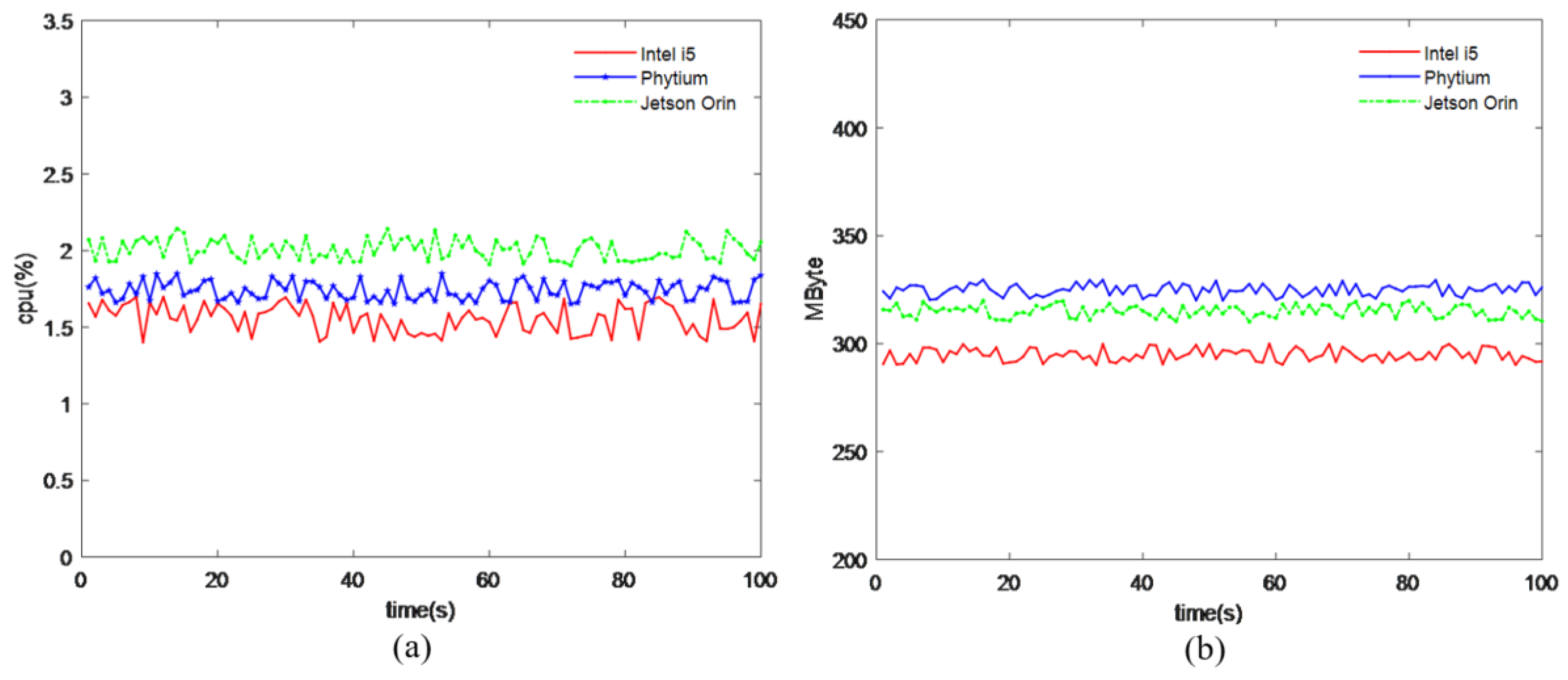
Figure 17a depicts the ARM OCCT simulation application for robots, utilizing the Reduced Instruction Set Architecture to efficiently handle graphics calculation tasks in the Linux X11 environment. This includes processing discrete spline trajectory and 3D topology model rendering demands. Leveraging ARM’s multi-threaded processing and reduced instruction can also match the x86’s performance.
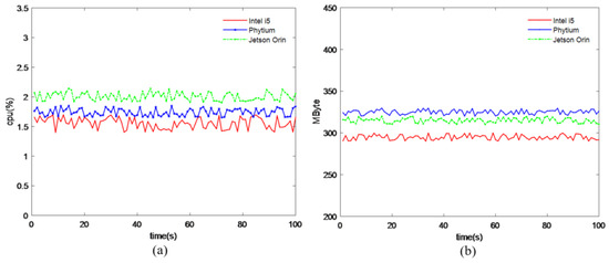
Figure 17.
Hardware resources: (a) CPU usage statistics; (b) memory usage statistics.
In Figure 17b, it is shown that the collaborative welding 3D robot model simulation program can run on a common device under an ARM Cortex processor. While the experimental results indicate that ARM architecture may have weaker memory utilization compared to the x86, considering the decreasing hardware cost, sacrificing memory for improved access efficiency becomes an optimized strategy.
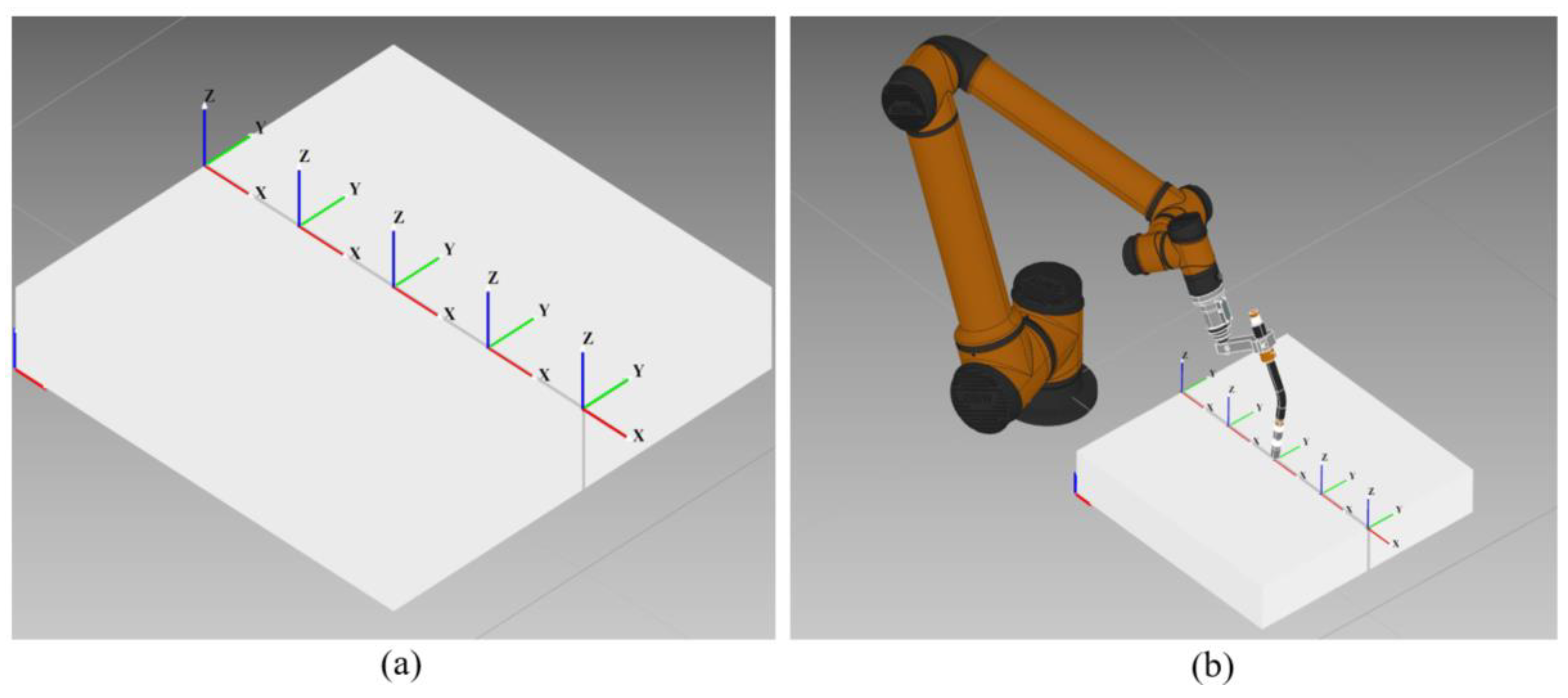
The sample of the GCPnts_UniformAbscissa class in the simulation software allows for a uniform distribution of points to be computed on a curve, enabling an AUBO-I10 kinematics simulation of metal-layer welding trajectories for V-shaped weld seams as depicted in Figure 18a,b. The simulation results indicate a smooth welding trajectory posture, effectively avoiding collisions between the welding torch and workpiece, thus verifying the correctness of our metal welding trajectory planning.

Figure 18.
Simulation planning: (a) normal vector; (b) robot simulation.
Three groups of independent robot welding tests were carried out under the parameters as shown in Table 4.
Table 4.
Experimental parameters of welding for V Groove of Q890.
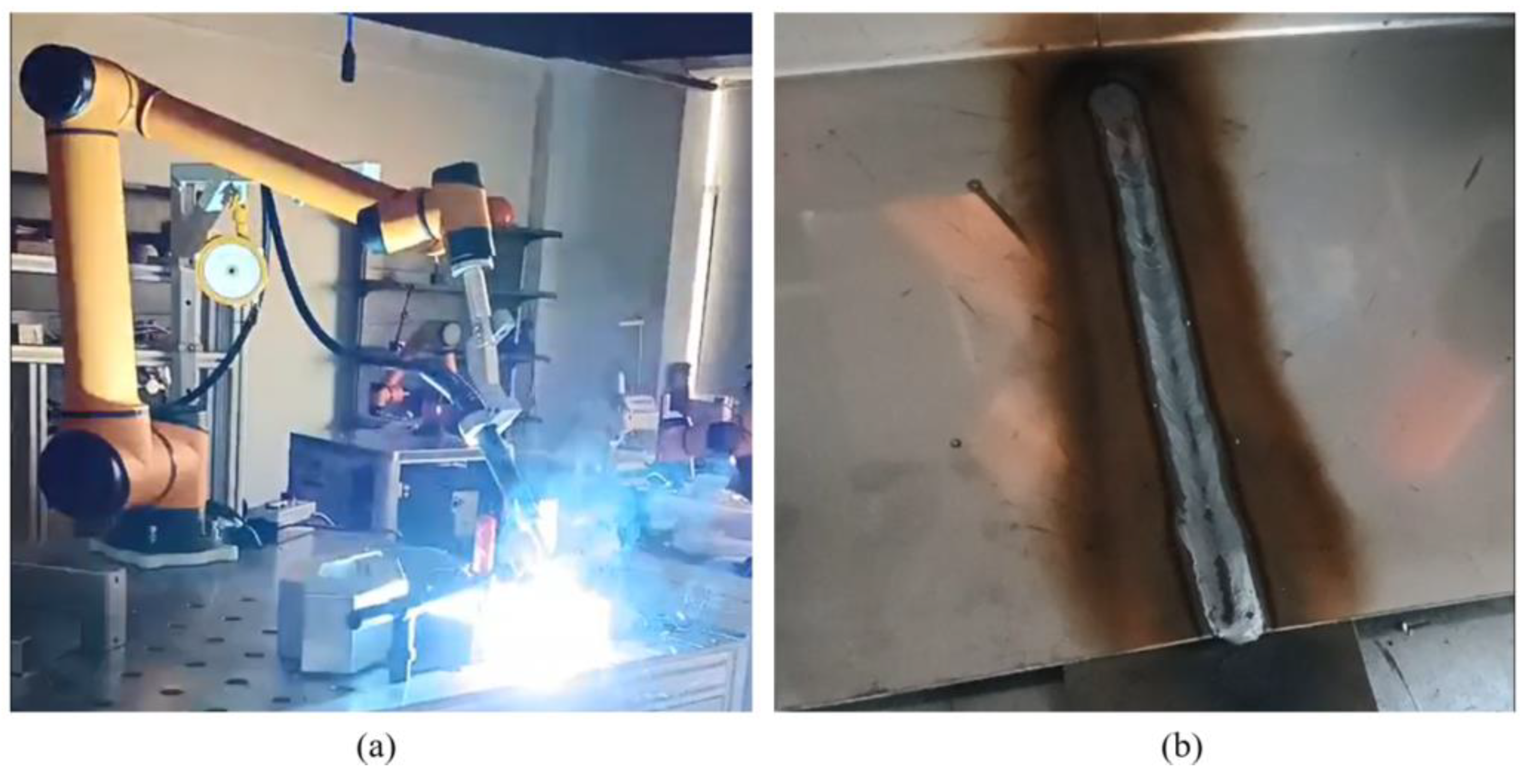
It was observed that, during the welding process, the weld metal was uniformly stacked with a very even trajectory on the surface. The weld seams were filled densely during the welding process, as shown in Figure 19a,b.
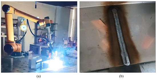
Figure 19.
Simulation planning: (a) real robot; (b) welding result.
Finally, a finite element simulation can be conducted in FreeCAD 0.19 as illustrated in Figure 20a,b. This involves analyzing two Q890 steel plates with an approximate groove and a root gap of 2 mm intended for welding. By adjusting the model to different heat temperatures according to experimental requirements, an intuitive observation of the Q890’s welding beam result could be achieved. Compared to the welding result in the above experiment, it could be observed that the steel surface of Q890 was stable and smooth and there was no obvious welding slag splash.
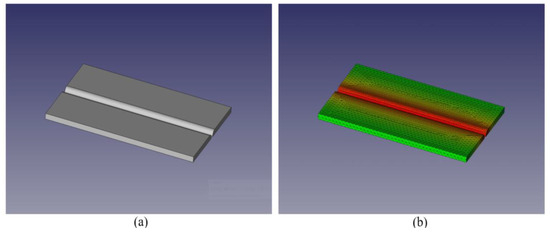
Figure 20.
Diagram of finite element simulation: (a) Q890 steel; (b) material analysis.
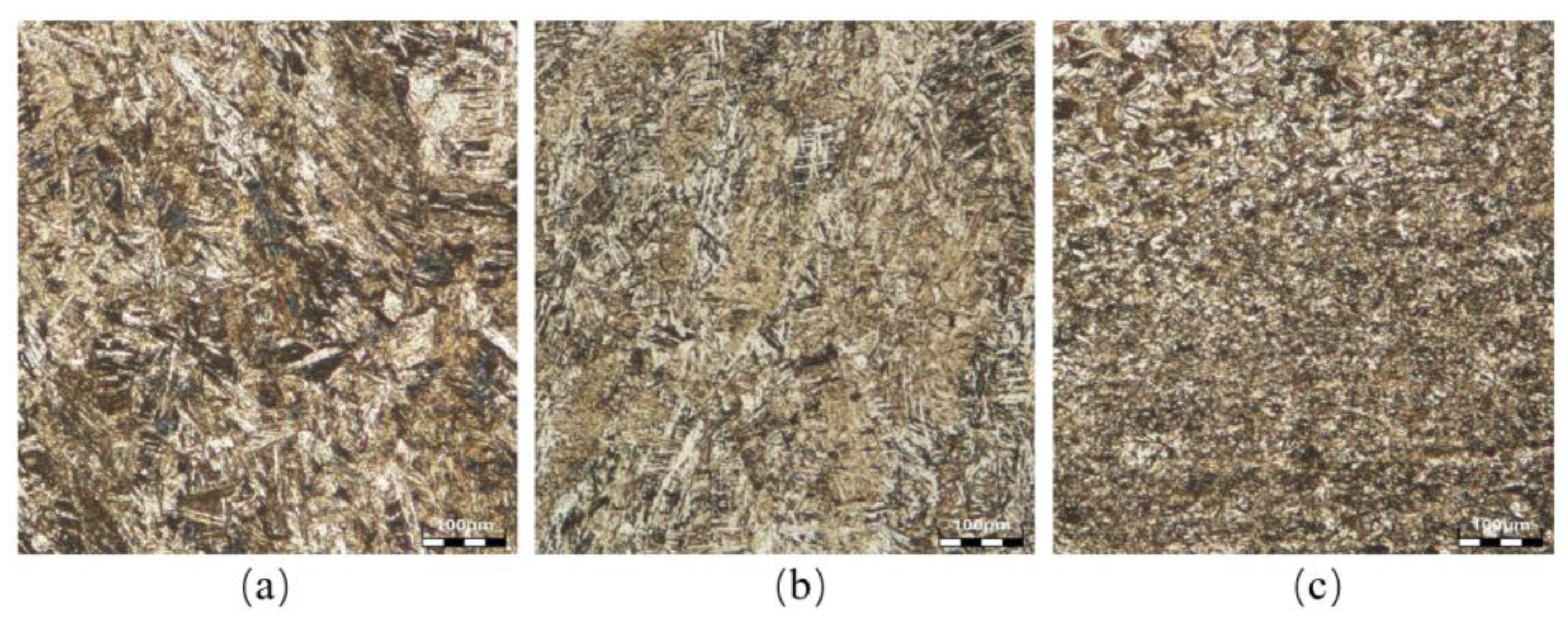
When the welding experiment was performed according to the preheating temperature in Table 4, it could be inferred from the experiment that, when the temperature is set at 25 °C or 55 °C, the cracks appear in the weld and root of the sample, as shown in Figure 21a,b.
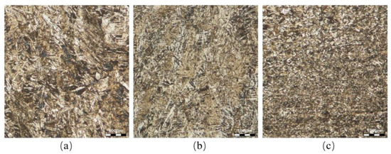
Figure 21.
Microstructure of Q890 with different welding preheating (a) 25 °C; (b) 55 °C; (c) 75 °C; scale bar on microstructure figure. The unit is 100 μm.
But there were no cracks on the surface of the Q890 sample when temperature was greater than 75 ℃. Compared to different preheating temperatures, the rate of crack generation decreased at 75 °C. So, when the temperature is greater than 75 °C, there are no weld defects such as an undercut or porosity on the surface of the weld seam, as shown in Figure 21c. The correctness and feasibility of offline programming trajectories for metal welding have been verified. This indicates that the implementation of the welding process is effective. The offline programming on ARM for metal-layer welding has been validated.
5. Conclusions
- (1)
- The ARM simulation design proposed in the previous section has been successfully verified using a sample, allowing the welding automation application to use the 3D geometry engine OCCT and Qt modules as required. This verification ensures the performance of the mode; while also confirming that the OpenGL ES 3.0+ and MESA drivers can support OpenCasCade 7.5.0 and Qt 5.15.0 in the QGLWidget interface. A STEP model of the collaborative robot has been rendered, the workpiece model has been imported, and the welding torch tool has been assembled to realize human–computer interaction functionality. Furthermore, it demonstrates that the ARM Linux environment can serve as a bridge for 3D model and image rendering, making OCCT 3D geometry modeling and welding simulation possible under the ARM architecture.
- (2)
- The Part Compound functionality of FreeCAD 0.19 has been utilized to complete the calibration of the base coordinates of the collaborative robot model’s STEP file. The calibration results can be checked through QGLWidget, indicating that the simulation software can handle there being independence between the main control graphics’ SoC and the corresponding instruction set module effectively for industrial robot applications. Through industrial digital simulation experiment, various motion parameters on the spline surface are obtained, verifying that a collaborative welding robot based on ARM can achieve the design goal. This lays the foundation for studying trajectory 3D simulation and rendering ARM automation.
- (3)
- In summary, it can be seen that an automatic collaborative welding robot simulation under ARM SoC has been realized with efficiency while providing an alternative solution to the hardware and software used in previous simulation systems. In addition to the previously mentioned robot simulation design, another robot simulation system supporting OpenGL ES 3.0+ under ARM may be suitable for welding trajectory simulation by leveraging this architecture at a lower price point.
Author Contributions
Conceptualization, S.G., H.G. and Y.G.; methodology, S.G., H.G. and Y.G.; formal analysis S.G. and Y.G.; investigation, S.G. and H.G.; writing—original draft preparation, H.G., S.G. and Y.G.; writing—review and editing, S.G., H.G. and Y.G.; finite experiments, H.G. and W.Z. All authors have read and agreed to the published version of the manuscript.
Funding
These works were funded by the Fundamental Research Program of Shanxi Province (No. 202103021224266).
Data Availability Statement
The data presented in this study are available on request from the corresponding author due to specify the reason for the restriction.
Acknowledgments
The authors would like to thank the AUBO Division of Robotics and Intelligent Manufacturing systems for cooperating and helping.
Conflicts of Interest
The authors declare that they have no known competing financial interests or personal relationships that could have appeared to influence the work reported in this paper.
References
- Wan, S.; Zhang, X.; Xu, M.; Wang, W.; Jiang, X. Region-adaptive path planning for precision optical polishing with industrial robots. Opt. Express 2018, 26, 23782–23795. [Google Scholar] [CrossRef] [PubMed]
- Luo, H.; Fu, J.; Jiao, L.; Liu, G.; Yu, C.; Wu, T. Kinematics and dynamics analysis of a new-type friction stir welding robot and its simulation. Adv. Mech. Eng. 2019, 11, 1687814019866518. [Google Scholar] [CrossRef]
- Gong, Y.; Huang, T.; Ma, Y.; Jeon, S.; Zhang, J. MTrajPlanner: A Multiple-Trajectory Planning Algorithm for Autonomous Underwater Vehicles. IEEE Trans. Intell. Transp. Syst. 2023, 24, 3714–3727. [Google Scholar] [CrossRef]
- Yan, S.; Wang, W.; Geng, J.; Wang, N.; Liu, Q. Research on 3D Visualization Simulation System of Deck Crew Based on OpenGL Technology. J. Phys. Conf. Ser. 2020, 1550, 032088. [Google Scholar] [CrossRef]
- Banović, M.; Vasilopoulos, I.; Walther, A.; Meyer, M. Algorithmic differentiation of an industrial airfoil design tool coupled with the adjoint CFD method. Optim. Eng. 2020, 21, 12211242. [Google Scholar] [CrossRef]
- Róth, Á. Algorithm 992: An OpenGL- and C++-based Function Library for Curve and Surface Modeling in a Large Class of Extended Chebyshev Spaces. ACM Trans. Math. Softw. 2019, 45, 1–32. [Google Scholar] [CrossRef]
- Ayse, Y. Graph-Waving architecture: Efficient execution of graph applications on GPUs. J. Parallel Distrib. Comput. 2021, 148, 69–82. [Google Scholar]
- Unterguggenberger, J.; Kerbl, B.; Wimmer, M. Vulkan all the way: Transitioning to a modern low-level graphics API in academia. Comput. Graph. 2023, 111, 155–165. [Google Scholar] [CrossRef]
- Rong-Xia, L. Design of Mobile Control system for wheeled Mobile Robot based on embedded ARM Technology. J. Phys. Conf. Ser. 2019, 1168, 022106. [Google Scholar] [CrossRef]
- Seemal, A.; Philip, W. Kinematics Analysis of 6-DoF Articulated Robot with Spherical Wrist. Math. Probl. Eng. 2021, 2021, 1–11. [Google Scholar]
- Postigo, J.A.; Garaigordobil, A.; Ansola, R.; Canales, J. Topology optimization of Shell–Infill structures with enhanced edge-detection and coating thickness control. Adv. Eng. Softw. 2024, 189, 103587. [Google Scholar] [CrossRef]
- Suresh, V.; Liu, W.; Zheng, M.; Li, B. High-resolution structured light 3D vision for fine-scale characterization to assist robotic assembly. In Dimensional Optical Metrology and Inspection for Practical Applications X; SPIE: Bellingham, WA, USA, 2021; p. 11732. [Google Scholar]
- Yin, Y.; Wang, T.; Wang, Z.; Huang, Z.; Shen, X.; Zhou, J. Research and Development of Casting Process CAD System for Steel Casting based on OpenCASCADE and wxWidgets. Procedia Manuf. 2019, 37, 348–352. [Google Scholar] [CrossRef]
- Va, H.; Choi, M.-H.; Hong, M. Parallel Cloth Simulation Using OpenGL Shading Language. Comput. Syst. Sci. Eng. 2022, 1, 427–443. [Google Scholar] [CrossRef]
- Chauhan, S.S.; Khare, A.K. Kinematic Analysis of the ABB IRB 1520 Industrial Robot Using RoboAnalyzer Software. Evergreen 2020, 7, 510–518. [Google Scholar] [CrossRef]
- Su, X.; Ma, C.; Yuan, X. Adjoint-Based Geometrically Constrained Aerodynamic Optimization of a Transonic Compressor Stage. J. Therm. Sci. 2019, 28, 850–861. [Google Scholar] [CrossRef]
- Urrea, C.; Saa, D. Design, Simulation, Implementation, and Comparison of Advanced Control Strategies Applied to a 6-DoF Planar Robot. Symmetry 2023, 15, 1070. [Google Scholar] [CrossRef]
- Matsumura, K.; Zohouri, H.R.; Wahib, M.; Endo, T.; Matsuoka, S. AN5D: Automated Stencil Framework for High-Degree Temporal Blocking on GPUs. In Proceedings of the 18th ACM/IEEE International Symposium on Code Generation and Optimization, San Diego, CA, USA, 22–26 February 2020. [Google Scholar] [CrossRef]
- Piraccini, G.; Schwander, F.; Serre, E.; Giorgiani, G.; Scotto D’Abusco, M. Spatial adaptivity in SOLEDGE3X-HDG for edge plasma simulations in versatile magnetic and reactor geometries. Contrib. Plasma Phys. 2022, 62, e202100185. [Google Scholar] [CrossRef]
- Zhadchenko, A.V.; Mamrosenko, K.A.; Giatsintov, A.M. Porting X Windows System to Operating System Compliant with Portable Operating System Interface. Int. J. Adv. Comput. Sci. Appl. 2020, 11, 221378389. [Google Scholar] [CrossRef]
- Wang, M.; Jing, J.; Gao, S.; Bian, P.; Ma, Y.; Zhou, N. Improved adaptive tessellation rendering algorithm. Technol. Health Care Off. J. Eur. Soc. Eng. Med. 2023, 31, 81–95. [Google Scholar] [CrossRef] [PubMed]


Disclaimer/Publisher’s Note: The statements, opinions and data contained in all publications are solely those of the individual author(s) and contributor(s) and not of MDPI and/or the editor(s). MDPI and/or the editor(s) disclaim responsibility for any injury to people or property resulting from any ideas, methods, instructions or products referred to in the content. |
© 2024 by the authors. Licensee MDPI, Basel, Switzerland. This article is an open access article distributed under the terms and conditions of the Creative Commons Attribution (CC BY) license (https://creativecommons.org/licenses/by/4.0/).