Article

Effect of Y2O3 Content on Microstructure and Wear Resistance of Laser Cladding Layer of Stellite-6 Alloy

1
College of Mechanical and Electrical Engineering, Wenzhou University, Wenzhou 325035, China
2
Rui’an Graduate College, Wenzhou University, Wenzhou 325206, China
3
Zhejiang Provincial Key Laboratory of Laser Processing Robots, Machinery Industry Key Laboratory of Laser Processing and Testing, Wenzhou 325035, China
4
Zhejiang Keteng Seiko Machinery Co., Ltd., Wenzhou 325205, China
*
Author to whom correspondence should be addressed.
Processes 2024, 12(6), 1119; https://doi.org/10.3390/pr12061119
Submission received: 24 April 2024 / Revised: 19 May 2024 / Accepted: 24 May 2024 / Published: 29 May 2024
(This article belongs to the Special Issue Heat Processing, Surface and Coatings Technology of Metal Materials)

Abstract

:
Laser cladding technology is an effective surface modification technique. In order to prepare coating with excellent properties on the surface of the cold heading die punch, stellite-6 cladding coating with different proportions of Y2O3 was prepared on the surface of W6Mo5Cr4V2 high-speed steel using laser cladding technology in this paper. The effects of different Y2O3 contents on the macroscopic morphology, microstructure, phase analysis, microhardness, and tribological properties of the stellite-6 coatings were investigated. It was determined that the optimal Y2O3 content for the stellite-6 powder was 2%. The results showed that the coating with 2%Y2O3 had the least number of pores and cracks and exhibited good surface flatness when joined. The microstructure became finer and denser, composed mainly of branch, cellular, equiaxed, and columnar grains. The coating consisted mainly of γ-Co, Fe-Cr, and Co3Fe7 strengthening phases, indicating good metallurgical bonding between the coating and the substrate. The average microhardness reached 539 HV when 2%Y2O3 was added, a 15.2% increase compared with the unmodified multilayer coating. The friction coefficient of the clad layer was 0.356, a 21.8% improvement over the unmodified stellite-6 coating. The average worn area of the cross-section was 3398.35 μm2, a reduction of approximately 27.8% compared with the unmodified stellite-6 clad layer. The wear surface primarily exhibited abrasive wear, with fewer cavities and a smoother surface.

1. Introduction

When cold heading molds work under alternating loads of reciprocating friction and impact, problems such as local detachment of the punch and brittle cracking often occur. The resulting heat from continuous operation significantly reduces the material’s hardness. Laser cladding, or laser coating, is a sophisticated material surface treatment technique that employs a high-energy laser to deposit and rapidly fuse alloy powder with the substrate. This process fuses the cladding material onto the base, resulting in a functionally enhanced coating through metallurgical bonding [1]. The cladding layer exhibits a high density and robust adhesion, thereby imparting exceptional wear resistance, corrosion resistance, and thermal oxidation stability [2,3]. Laser cladding, a prevalent technique in aerospace, automotive, and mold manufacturing, significantly enhances material properties and prolongs component service life [4].
Co-based self-fluxing alloy powder has been widely used in the engineering field because of its excellent properties, such as corrosion resistance, wear resistance, and high-temperature oxidation resistance [5]. Yun et al. [6] prepared a Co-based cladding coating on the surface of Inva alloy, a low expansion alloy, using laser cladding, and the research showed that the wear resistance and oxidation resistance of the surface of Inva alloy were significantly improved. Qin et al. [7] conducted the heat treatment of Co-Ni coating prepared by laser cladding technology, and the study showed that the microhardness of the cladding layer increased with the heat treatment temperature rising from 200 °C to 400 °C. Fan et al. [8] prepared Co-based cladding coatings (Co + 15%WB, Co + 45%WB) on EH40 steel. The research shows that the cladding layer with 45%WB added has a lower friction coefficient and wear rate and has good wear resistance.
Rare earth elements consist of lanthanides and actinides in the periodic table. They exhibit high chemical activity and play a significant role in enhancing the properties of alloys [9]. In the coating of rare earth elements, due to their very active characteristics, rare earth elements preferentially gather at the grain boundaries, which can well restrict and hinder the growth of crystal structures. Therefore, the addition of rare earth elements can refine the crystal structure formation process [10,11]. During the cladding process, rare earth elements can act as heterogeneous nuclei in the coating, effectively enhancing the efficiency of nucleation. Additionally, compounds reacting with rare earth elements can also serve as heterogeneous crystal nuclei, promoting both grain refinement and reducing the inter-granular gap. The addition of rare earth elements in the cladding powder can improve the absorption rate of laser energy of the powder material and increase the fluidity of the liquid metal during the cladding process, which is conducive to the discharge of gas and slag in the cladding layer, and reduce the composition segregation during the flow process, resulting in uniform microstructure and fewer defects [12]. A large number of studies have shown that an appropriate amount of rare earth elements added to the cladding powder can improve the coating performance well, while an excessive amount will degrade the coating performance [13]. Chen et al. [14] prepared WC/Ni60A-doped La2O3 on the surface of 45 steel matrices using laser cladding technology, and the study showed that rare earth La2O3 refined the grain, improving the microhardness and wear resistance of the sample. In Du et al. [15], a WC-containing composite coating was prepared on the surface of Invar alloy, and the changes in the microstructure and properties of the overlay coating with the addition of Y2O3 were investigated. The study revealed that the incorporation of Y2O3 significantly increased the coating thickness, enhanced melting efficiency, and led to significantly higher hardness and wear resistance in the Y2O3-added overlay coating compared with the base material.
This study used laser cladding technology to prepare stellite-6 cladding coatings with different proportions of Y2O3 added on W6Mo5Cr4V2 high-speed steel. The influence of Y2O3 content on the macroscopic morphology, microstructure, phase analysis, microhardness, and friction wear of stellite-6 coatings was studied.

2. Experiment

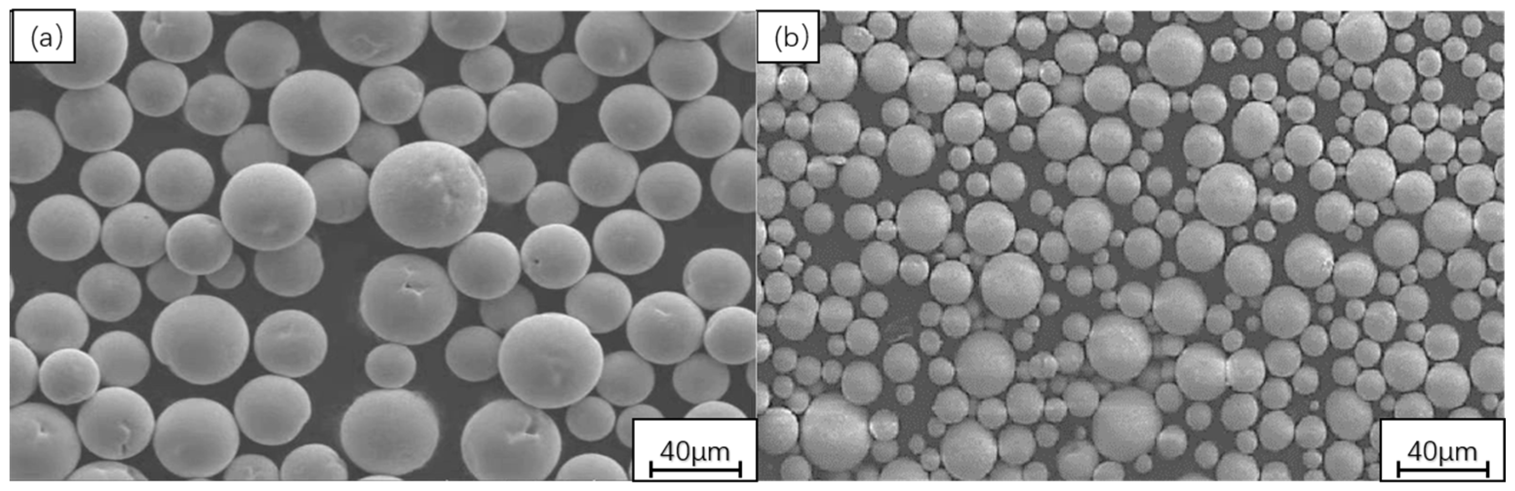
2.1. Experimental Materials

The W6Mo5Cr4V2 high-speed steel, known for its high strength, is commonly used in cold forging dies. Therefore, the experimental substrate material is W6Mo5Cr4V2 high-speed steel, with dimensions of 100 mm × 60 mm × 10 mm. Prior to the overlay process, the surface of the high-speed steel was thoroughly cleaned using 120-grit and 800-grit SiC sandpaper, ensuring it was smooth and free of oxide film, and cleaned with propanol to remove oil stains. The chemical composition of this material is presented in Table 1.
In order to study the effect of Y2O3 on the stellite-6 cladding layer, the stellite-6 + X-Wt %Y2O3 (x = 2, 3, 4) composite coating was prepared. Table 2 shows the chemical element composition of stellite-6; Figure 1a shows the micromorphology of stellite-6 self-fluxable cobalt-based alloy powder with a particle size of 44~149 μm; Figure 1b shows the microstructure of the Y2O3 powder, with particle sizes ranging from 30 to 100 μm. The micromorphology shows that the powder has a regular spherical structure with uniform size, which makes it have excellent fluidity. Before the experiment, Y2O3 powder and stellite-6 powder were placed in a ball mill in proportion (2% Y2O3 + 98% stellite-6; 3% Y2O3 + 97% stellite-6; 4% Y2O3 + 96% stellite-6) at a rotational speed of 350 r/min, mixed for 3 h, and then placed in a vacuum drying oven. The mixture was kept at 180 °C for 2–3 h for drying treatment.

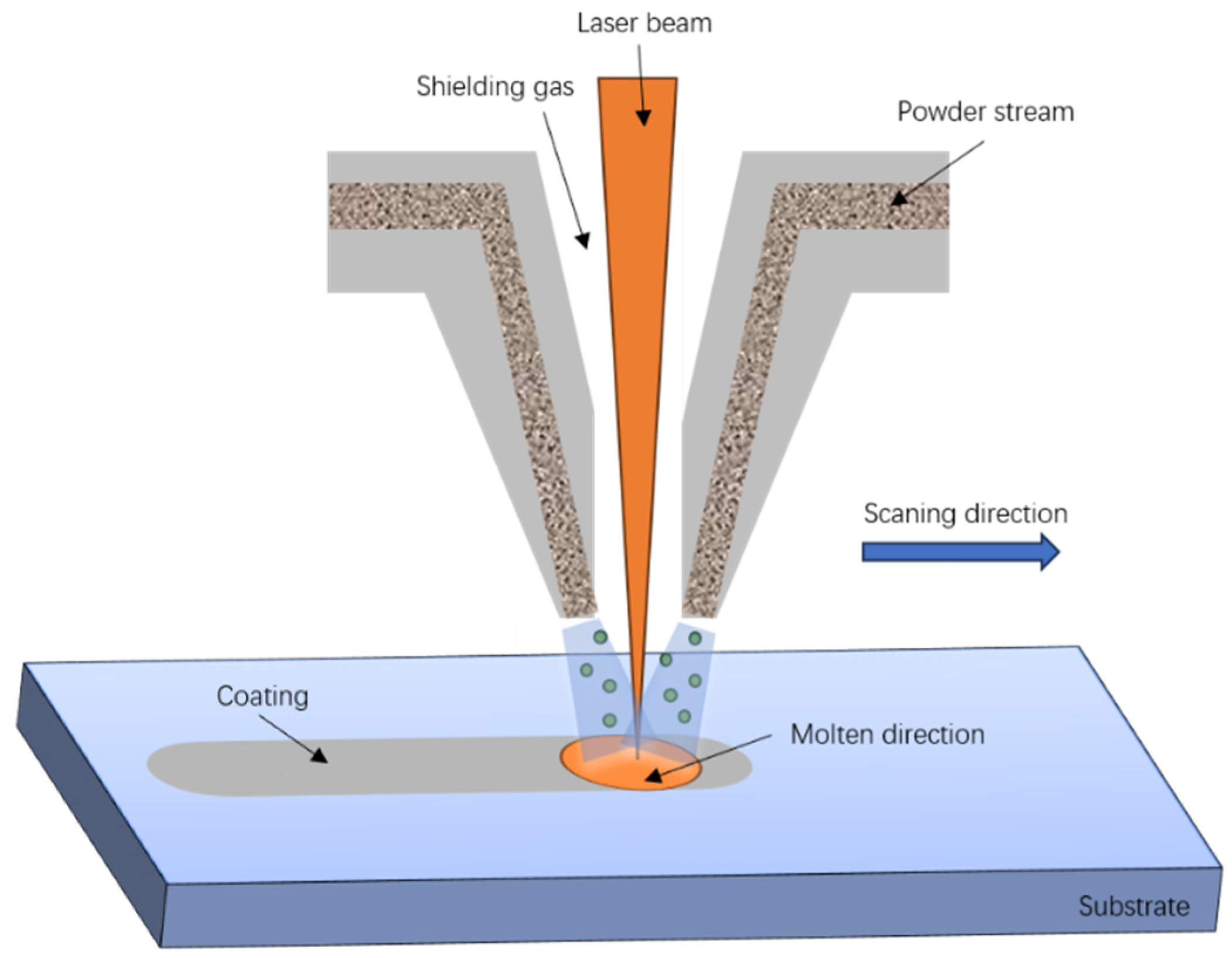
2.2. Experimental Methods

The laser cladding equipment used in this experiment had 6-kW high power, with a wavelength of 810–940 nm, a focal length of 165 mm, and a laser spot diameter of 3 mm, which is circular in shape. Synchronous laser cladding, as shown in Figure 2, was adopted in this study. Based on previous process parameter studies, the process parameters in Table 3 were employed to prepare the laser cladding coating. The laser cladding system consists of a powder feeding device, including a coaxial powder nozzle and a powder feeder, a CNC digital control system, a water-cooling system that cools the laser with deionized water to enhance work efficiency, and a gas protection device. During the cladding process, argon gas was blown out through the side to prevent the oxidation of the cladding layer. The system was capable of movement in the X, Y, and Z axes, enabling laser cladding on various workpiece surfaces. After testing, multi-pass cladding layers were cut into 10 mm × 10 mm × 10 mm pieces. The MP-2B metallographic sample polishing machine was used, with 120-mesh sandpaper for rough grinding, followed by 400-, 600-, 800-, 1000-, and 1500-mesh sandpaper for fine grinding, resulting in a mirror-like finish. The polished samples were etched with an aqua regia solution (3HCL:1HNO3) and observed under the German brand Zeiss Axiolab metallographic microscope for their microstructure analysis.
FRINGE EV X-ray diffractometer, produced by Suzhou Langsheng Scientific Instrument Co., Ltd. (Suzhou, China), is a new X-ray diffractometer. The test parameters were as follows: The target was CrKβ, the angle range of 2θ was −3°~+150°, the X-ray tube power was 1200 W, and the scanning speed was 3°/min. MDI Jade 5 software was used to search the phase of the peak intensity detected by the device at the corresponding angle so as to determine the phase contained in the test sample, as well as the crystal face index, crystal face spacing, and lattice constant corresponding to the diffraction peak.
The morphology of the cladding layer, the surface morphology of the metallographic sample, and the microstructure of the sample after friction and wear were observed using a scanning electron microscope (JSM-6510LA) from Hong Kong Furuibo International Limited. The samples were quantitatively analyzed using energy dispersive spectrometry (EDS).
After melting, the cross-section of the sample was polished and cleaned with acetone. The microhardness test was carried out on an HVS-100A digital microVickers hardness tester with an experimental load of 10 N and a dwell time of 15 s. A point of 0.2 mm was taken away from the surface of the fusion layer on the cross-section of the fusion layer, and a point was taken every 0.2 mm downwards (2%Y2O3, 3%Y2O3, 4%Y2O3). Seven hardness points were taken from each sample, the hardness of each point was measured three times, and the average value was taken. The accuracy was 10−2 HV.
The friction and wear experiments were carried out on the MS-T3100 friction and wear tester, and the friction form was dry sliding friction. The cladding sample made of laser cladding multi-lap was cut into a 10 mm × 10 mm × 10 mm cubic sample. The main parameters of the friction and wear experiment were as follows: Al2O3 ceramic ball was used, the load was 10 N, the friction frequency was 5 HZ, the friction radius was 2 mm, and the experiment time was 30 min. The model OLS4100 3D confocal microscope was used to study the wear morphology of the cladding layer. Three cross-section wear areas were measured on the three-dimensional topography of the wear surface to obtain the cross-section average wear area to reflect the wear trend of the cladding layer. The cross-section area measurement accuracy was 10−4 μm2.

3. Results and Discussion

3.1. Macroscopic Morphology

Figure 3 shows the macroscopic morphology of the coating with varying Y2O3 content. The overall surface morphology of the cladding layer was good, but there were still noticeable pits. The stellite-6 cladding coating with 2%Y2O3 had some pits, good flatness, and unmelted powder on the surface. It had the smallest size and number of visible pits and had good flatness, with less unmelted powder in the coating. The stellite-6 coating with 3%Y2O3 significantly increased the number and size of pores. The stellite-6 cladding coating with 4%Y2O3 had more unmelted powder, resulting in poorer overall cladding layer quality. The appropriate addition of yttrium oxide yielded better cladding coatings. However, excessive rare earth oxide addition negatively impacted cladding layer fluidity, causing more pores and cracks.
Figure 4 shows the cross-sectional morphology of the coating with varying Y2O3 content. The cladding layer was significantly improved after adding rare earth elements, and it was well integrated with the matrix, forming a metallurgical bond. When 2%Y2O3 was added, as shown in Figure 4b, the coating had fewer pore cracks, and the cladding layer’s surface was relatively smooth. In Figure 4c, by adding 3% rare earth, Y2O3 clearly increased the number of pores in the cladding layer. Figure 4d also shows that adding 4%Y2O3 results in small pores. The appropriate addition of rare earth elements facilitates the formation of the cladding layer, whereas excessive amounts impede slag discharge, causing an uneven microstructure and resulting in defects [16].

3.2. Phase Composition
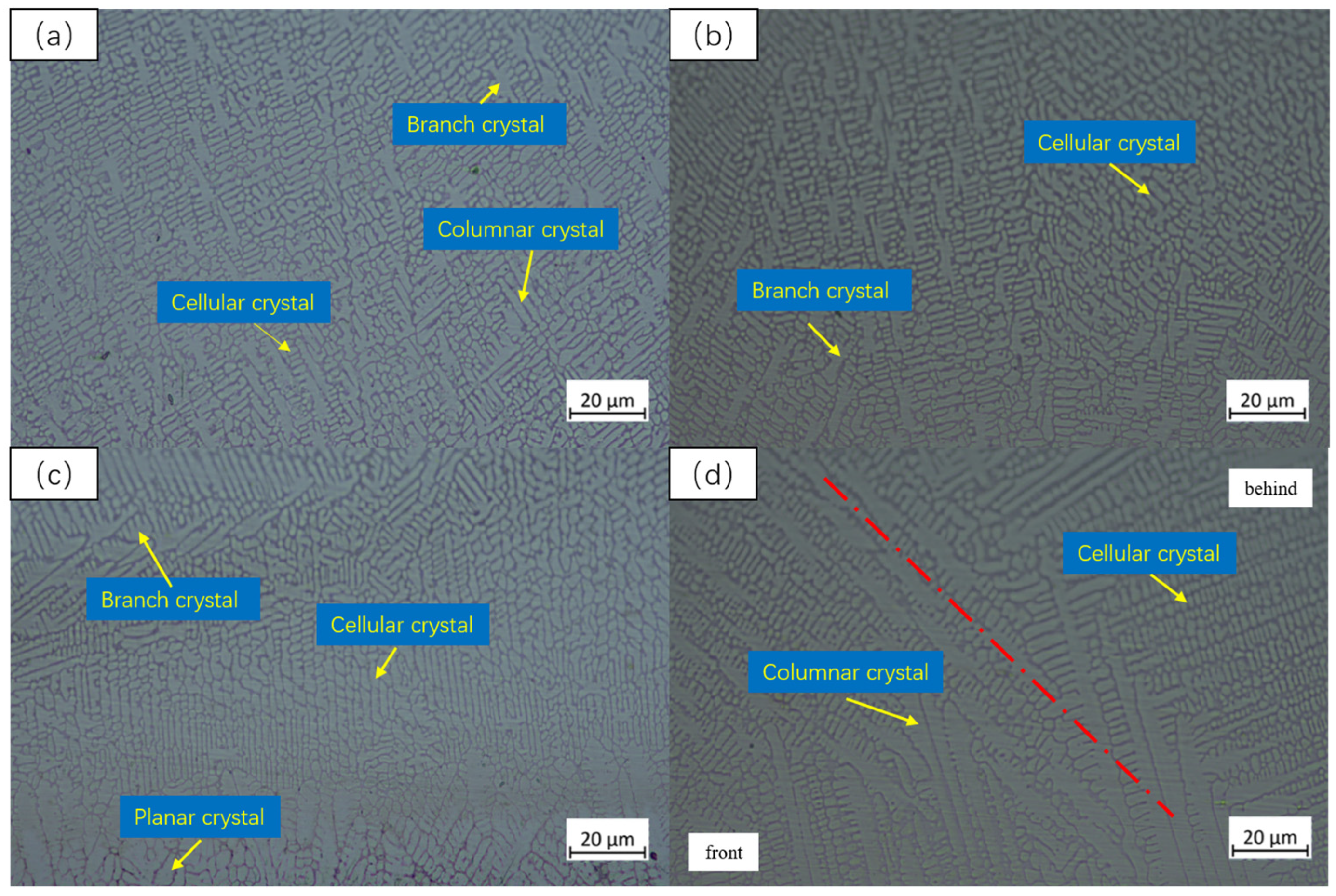
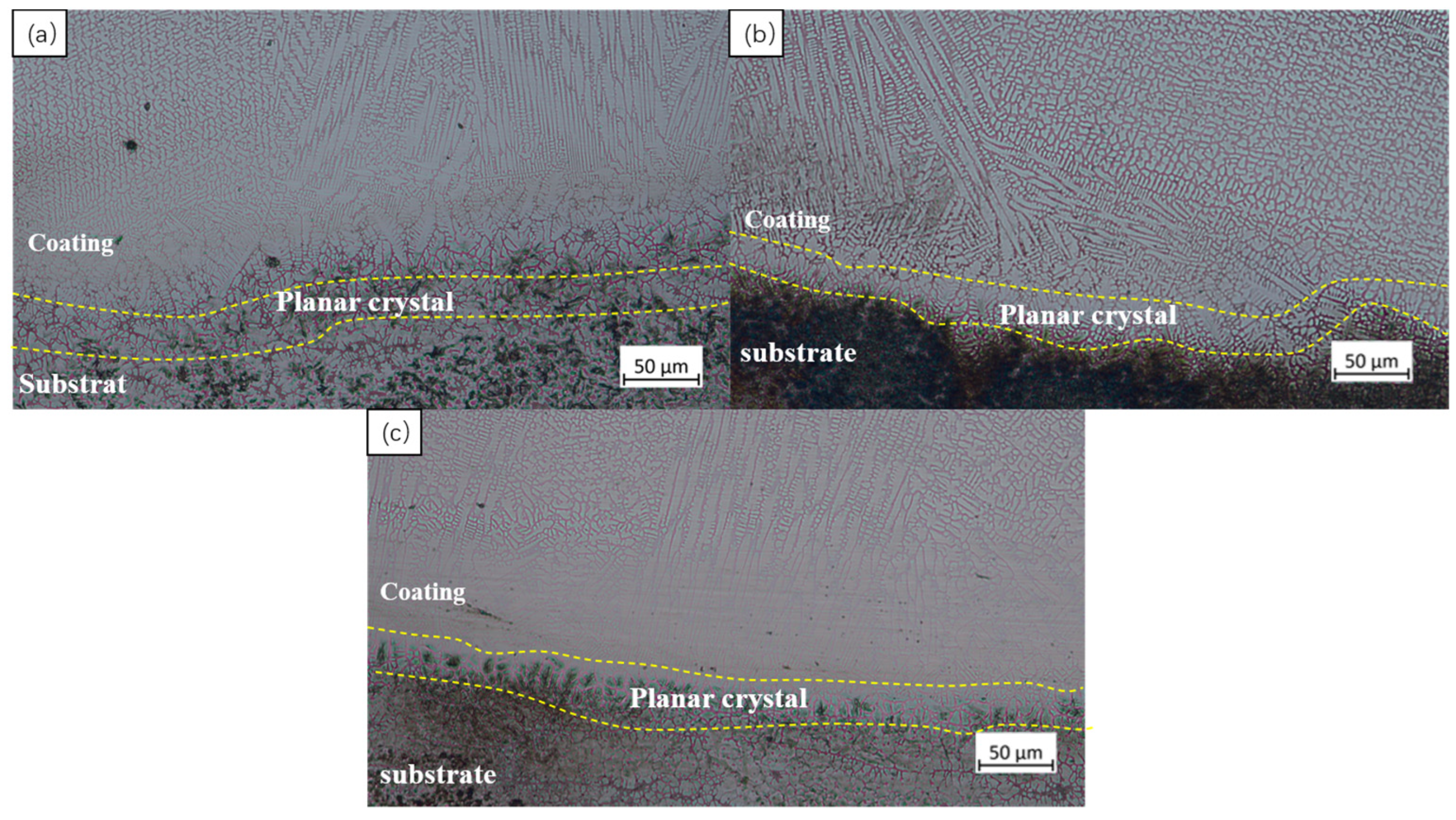
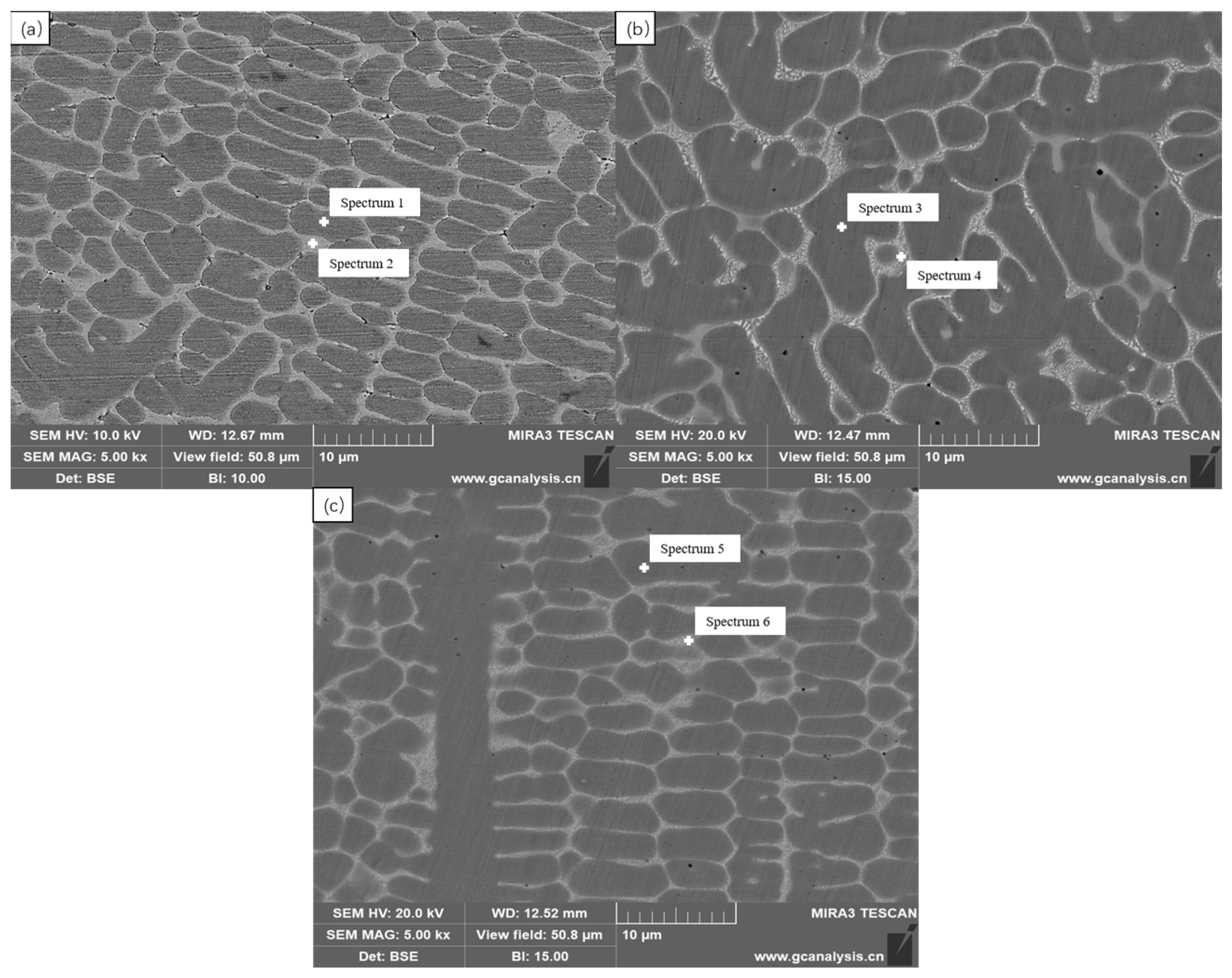
Figure 5 shows the X-ray diffraction pattern of coatings with varying Y2O3 contents. It can be seen from the figure that it was composed of γ-Co, Fe-Cr, Cr23C6, Co3Fe7, and other phases. When the peak value was 43°, the height of the diffraction peak rose with the increase in Y2O3 content. This indicates that Co and Cr from HSS enter the coating through the molten pool and react with the coating material to form various phase structures, and metallurgical bonding takes place between the coating and the substrate.

3.3. Microstructure

Figure 6, Figure 7 and Figure 8 show the microstructure of the cross-sections of stellite-6 cladding coatings with 2%, 3%, and 4%Y2O3 contents. A comparison of the upper regions in Figure 6a, Figure 7a and Figure 8a reveals that the grains in the top layer were generally finer compared with the middle and lower sections of the coatings. The upper layer of the 2%Y2O3-merged coating consisted of fine dendrites, numerous cellular grains, and columnar grains, forming a compact and uniform microstructure. The 3%Y2O3-merged coating’s upper layer had finer grains, with some dendrites remaining and a smaller inter-grain spacing. The 4%Y2O3-merged coating’s upper layer exhibited coarser grains, and their growth directionality was still noticeable. This indicates that excessive Y2O3 content leads to larger grains, potentially impacting the coating’s performance.
According to the comparison of the central structures in Figure 6b, Figure 7b and Figure 8b, the cladding coating with 2%Y2O3 was composed of fine dendrites, having small inter-granular distances and a relatively uniform regular distribution. The cladding coating with 3%Y2O3 consisted of dendrites and cellular and equiaxed crystals, with crystals becoming coarser. When 4%Y2O3 was added, more dendrites became coarse, and the arrangement between dendrites remained tight. An appropriate amount of Y2O3 can refine grains and improve crystal structure, while excessive rare earth elements can lead to coarse crystal structure.
From the bottom microstructure of Figure 6c, Figure 7c and Figure 8c, it can be seen that the cladding coating with 2%Y2O3 was composed of dendritic, cellular, and planar crystals in the bonding zone, with small inter-granular distance and uniform distribution. As the rare earth oxide content increased to 3% and 4%, the grain structure still became larger, and numerous fishbone crystals appeared. An appropriate amount of rare earth elements can form and aggregate at grain boundaries, inhibiting grain growth, altering the grain growth mode and rate, and refining the grain structure, thereby improving the mechanical properties and wear resistance of the cladding layer. However, excessive rare earth elements in the cladding coating can cause abnormal phase transformation, resulting in precipitated phases or non-uniform structure formation, affecting the mechanical properties and stability of the cladding layer.
In Figure 6d, Figure 7d and Figure 8d, the lap area of the Y2O3 coating with different ratios is applied. The coating consists mainly of columnar crystals and dendrites, and it is evident that the structure before the coating is larger than that after the coating. The coagulation time of the tissue in this region is extended, allowing the tissue to grow more.
Combined with the microstructure diagram and theoretical analysis, it can be seen that Y2O3 was decomposed in the laser cladding process, and the Y element was extremely active, which makes it easy to react with other elements in the cladding layer to generate new metalized elements [17,18,19], increase the number of new nucleation points, and refine the microstructure grains. Moreover, the Y element can reduce the Gibbs free energy required in the nucleation process, thereby increasing the nucleation rate and making the cladding microstructure fine and uniform. When the content of Y2O3 exceeds 2%, it is not conducive to the thinning of the tissue, and relatively coarse cellular crystals are formed.
As shown in Figure 9, the cross-sectional microstructure of the bonding zone is mainly composed of planar crystals. Coarse dendrites, cellular crystal, and a network-like eutectic structure precipitated between grains appear from the bonding zone upwards. The characteristics of rapid melting and solidification in laser cladding led to the occurrence of element segregation with uneven chemical composition in the bonding area between the cladding layer and the substrate. Therefore, a transition zone without crystal nuclei was formed in this area, which was conducive to the growth of planar crystals. During the high-energy laser beam irradiation process, the liquid phase temperature in the bonding zone between the cladding powder and the substrate was high, and the degree of undercooling was low. Therefore, the cooling in this area was slow, and the crystallization rate was low, making it easy to form planar crystals. The undercooling gradually increased in the upper part of the bonding zone and its adjacent area. Due to the influence of the substrate dilution rate, a large amount of Fe elements in the substrate entered the coating without forming smaller crystal nuclei and generating coarse dendrites. The temperature gradient in the middle of the fusion coating was small, the undercooling increased, and the dilution rate had little effect, resulting in the generation of a large number of cellular crystals. The top tissue had the fastest cooling rate due to its minimum temperature gradient, proximity to the surface, and the blowing effect of the protected gas [20]. Moreover, the rare earth element Y acted as a heterogeneous nucleation point in the coating, thus forming a large number of equiaxed crystals and small network crystals.
The phase analysis of the middle of the laser cladding layer with different Y2O3 content was carried out by using an energy dispersive spectrometer. Figure 10a shows the SEM image of the middle microstructure of the 2%Y2O3 cladding coating. Two points were taken on the crystal and the grain boundary for point scanning, labeled Spectrum1 and Spectrum2 in the figure, respectively. Figure 10b shows the SEM image of the middle microstructure of the 3%Y2O3 cladding coating. Two points were taken on the crystal and the grain boundary for surface scanning, labeled Spectrum3 and Spectrum4 in the figure, respectively. Figure 10c SEM image of the middle microstructure of 4%Y2O3 cladding coating. Two points on the crystal and at the grain boundary were selected for surface scanning, labeled Spectrum5 and Spectrum6 in the figure, respectively.
Table 4 shows an EDS dot scan analysis of Y2O3 content. It can be seen from the table that there are more Fe and Co elements in Spectrum1, Spectrum3, and Spectrum5, and combined with the XRD patterns, it is inferred that there are Fe-Cr and γ-Co in Spectrum1, Spectrum3, and Spectrum5. Compared with Spectrum1, Spectrum3, and Spectrum5, Spectrum2, Spectrum4, and Spectrum6 contain more Cr elements, and more Fe-Cr phases are generated. Fe and Co elements of Spectrum1, Spectrum, and Spectrum5 mostly generate Co3Fe7 phases. Points Spectrum2 and Spectrum4 are enriched in C and Cr elements and have Cr23C6 phases. Points Spectrum2, Spectrum4, and Spectrum6 exhibit enriched C and Cr elements, with Cr23C6 phases. Due to the tendency of Y to aggregate at grain boundaries and its affinity for C [21], the C content is higher on Spectrum2, Spectrum4, and Spectrum6 than on Spectrum1, Spectrum3, and Spectrum5, which are not at grain boundaries. C enrichment leads to the precipitation of hard M23C6 and M7C3 carbides at the grain boundaries.

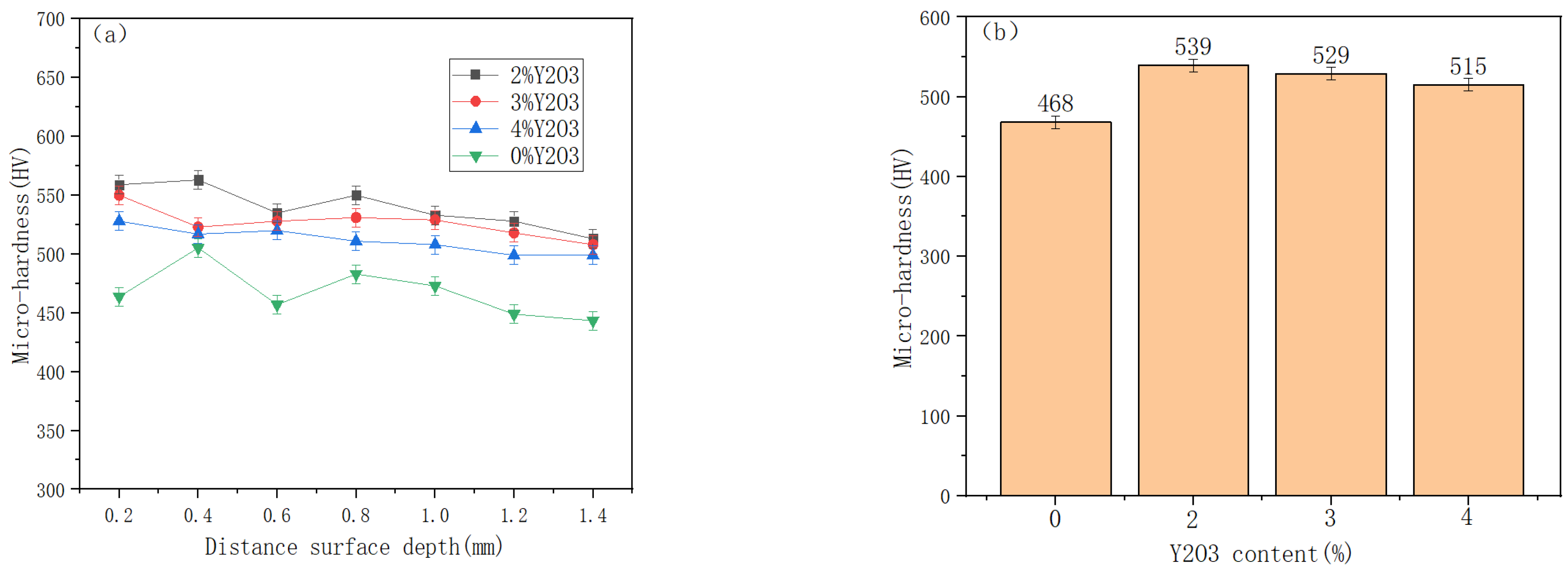
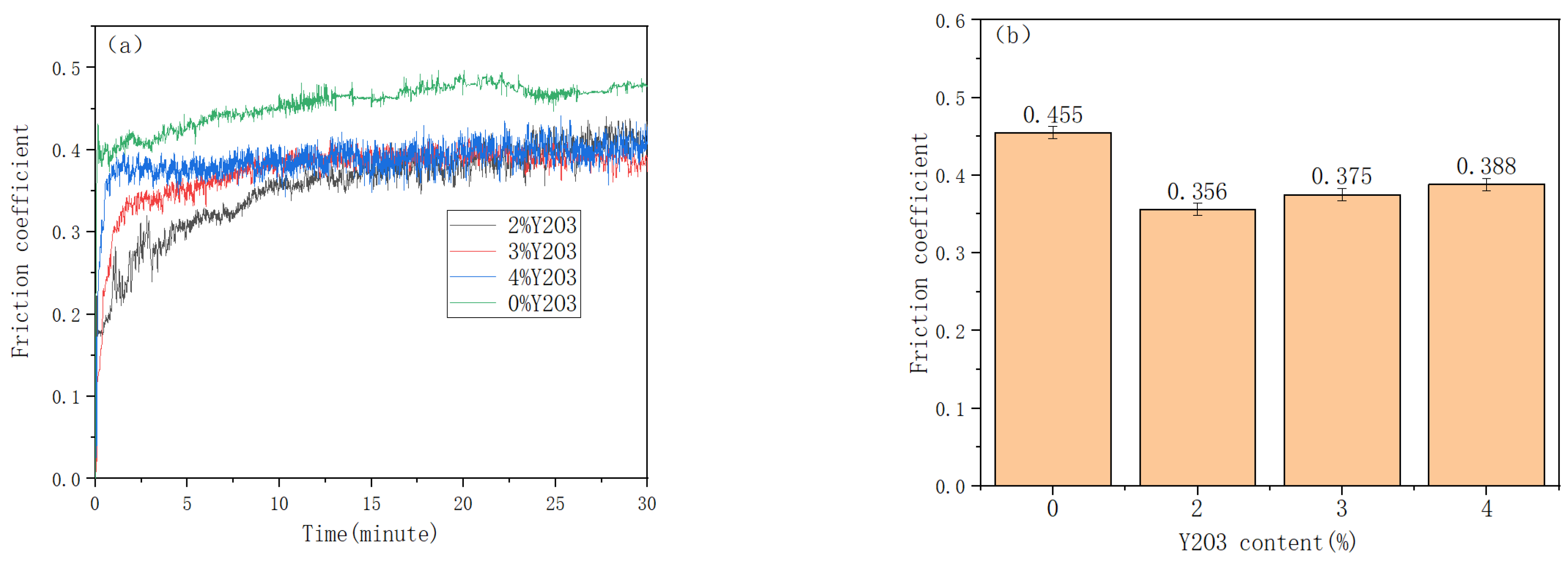
3.4. Microhardness and Friction Wear of Cladding Layer

Figure 11 shows the microhardness and average microhardness of coatings with different Y2O3 contents. As can be seen from the figure, the microhardness of the clad layer decreases gradually with increasing Y2O3 content. The highest average microhardness of 539 HV was achieved at a 2% Y2O3 content, which was approximately 15.2% higher than that of the multi-track cladded layer without Y2O3. An excessive amount of Y2O3 leads to a decrease in microhardness due to reduced pool mobility, coarser grain structure, and significant compositional segregation. Appropriate Y2O3 content enhances the hardness of the clad layer because a higher concentration of rare earth elements at grain boundaries reduces the driving force for grain growth, resulting in finer and denser grains. Compounds formed by rare earth elements with O and S elements during laser cladding can act as heterogeneous nucleation sites, improving nucleation efficiency. According to the Hall–Petch equation, grain refinement increases yield strength and hardness. Therefore, rare earth oxides can enhance the hardness of the clad layer [22,23]. An increase in Y2O3 content raises the overall melting point of the clad layer, reducing undercooling and lowering nucleation rates, leading to a coarser internal structure and a subsequent decrease in hardness.
Figure 12 shows the friction coefficient of the substrate and the cladding coating with different Y2O3 contents, and it can be seen that the friction coefficient of the coating was significantly lower than that of the substrate. The average friction coefficient of stellite-6 was 0.455, the average friction coefficient of the coating with 2%Y2O3 was 0.356, the average friction coefficient of the coating with 3%Y2O3 was 0.375, and the average friction coefficient of the coating with 4%Y2O3 was 0.388. Compared with the friction coefficient of stellite-6, the friction coefficient of the coating after adding rare earth yttrium oxide was reduced by about 21.8%. As can be seen from the figure, the average friction coefficient increases gradually with the increase in the content of Y2O3. It shows that the addition of the appropriate content of Y2O3 can refine the microstructure of the coating, improve the fluidity of the molten pool, further improve the plasticity of the cladding coating, and improve the yield strength of the coating to a certain extent. The addition of excessive Y2O3 will reduce the fluidity of the melt pool of the cladding coating in the laser cladding process and will also generate refractory compounds in the coating, resulting in a coarse coating structure and possible cracks. A large amount of rare earth elements at the grain boundaries will cause component segregation, block the crystal dislocation movement, and reduce the friction and wear performance of the cladding layer [24].
Figure 13 shows the wear surface topography of samples with different Y2O3 contents. It can be observed that there is no obvious crack on the surface of the cobalt-based cladding coating with Y2O3, indicating that there is no micro-brittle crack on the cladding coating. Figure 13a is the 3D topography of the wear surface of the cladding coating with stellite-6 added, and Figure 13(a1) is the square enlarged area of Figure 13a. It can be seen that the wear area of the wear surface is large, and there are many gullies. Figure 13b shows the 3D topography of the wear surface of the cladding coating with 2%Y2O3 added. In the square enlarged area of Figure 13(b1),b, obvious furrows and some traces of peeling can be seen, so abrasive wear and adhesive wear occur. The main reason for the furrow on the surface of the cladding layer is that the grinding ball and the surface are extruded and move relative to each other, which makes the coating surface peel off and accumulate from the extrusion center to both sides, resulting in wear particles. The ball-and-disc friction and wear machine rotates on the surface of the cladding layer, and the friction heat generated by repeated rotating motion softens the cladding coating, making the grinding ball and part of the cladding layer sticky, causing the surface to flake off and form an adhesive wear. Figure 13c,d shows the 3D morphology of the wear of the cladding coating with 3%Y2O3 and 4%Y2O3 added, respectively. Figure 13(c1,d1) shows the square enlarged areas of Figure 13c,d. It can be seen that with the increase in the content of Y2O3, a larger area of adhesive wear appears. Figure 14 shows the three-dimensional morphology of the wear surface of samples with different Y2O3 content. OLS4100 software is used to measure three cross-sectional wear areas on the three-dimensional topography of the wear surface to obtain the average cross-sectional wear area. The average cross-section wear area of the stellite-6 cladding layer was 4706.86 μm2, the average cross-section wear area of the 2%Y2O3 cladding layer was 3398.35 μm2, and the average cross-section wear area of the 3%Y2O3 cladding layer was 3661.44 μm2. The average cross-sectional wear area of the 4%Y2O3 cladding layer was 3933.05 μm2. The average cross-sectional wear area of 2%Y2O3, 3%Y2O3, and 4%Y2O3 cladding layers was reduced by 27.8%, 22.2%, and 16.4%, respectively, compared with stellite-6 without addition. Therefore, Y2O3 can effectively improve the wear resistance of the cladding layer, but the wear performance of the excess Y2O3 cladding layer is less improved.

4. Conclusions

The stellite-6 fusion coating with Y2O3 added a finer and denser microstructure compared with the non stellite-6 fusion coating, with a significant improvement in hardness and wear resistance. The stellite-6 cladding layer with 2% Y2O3 added had the best performance and formed a metallurgical bond with the substrate.
(1) The addition of an adequate amount of Y2O3 can improve the flatness of the cladding coating, reduce surface pits and slag, and decrease the cross-sectional appearance of cladding layer porosity, cracks, and other defects. This indicates that rare earth oxides enhance the fluidity of the molten pool and facilitate slag discharge, but excessive Y2O3 can cause excessive slag on the cladding layer’s surface, affecting its forming quality.
(2) The bonding zone between the cladding layer and the substrate is mainly composed of planar crystals. Above the bonding zone are coarse dendrites, cellular crystals, and network eutectic structures. The middle of the cladding layer is mainly composed of cellular crystals, while the top is composed of a large number of equiaxed crystals and small network crystals. From the bottom of the cladding layer to the top of the cladding layer, the grains gradually become finer. With an increase in Y2O3 content, the microstructure of the cladding layer’s crystals coarsens, and the 2%Y2O3 cladding layer has the finest microstructure.
(3) The coating was analyzed using XRD and EDS. It contained γ-Co, Fe-Cr, Co3Fe7, and other phases, indicating that Co and Cr from the high-speed steel entered the coating through the melt pool, forming various phase structures with the coating material and achieving metallurgical bonding between the coating and the substrate.
(4) The hardness of the cladding layer was inversely proportional to the content of rare earth oxides, with a hardness of 539 HV for the 2% Y2O3 cladding layer. Compared with the cladding coating without Y2O3, the average microhardness increased by about 15.2%. Rare earth elements refine the grain structure, enhancing yield strength and hardness, thus raising the coating’s hardness.
(5) As Y2O3 content increases, the average friction and wear coefficient gradually rise. The 2% Y2O3 coating had the lowest coefficient of friction and wear, at 0.356, which is approximately 21.8% lower than the stellite-6 coating without addition. The average cross-sectional wear area of the cladding layer was 3398.35 μm2, which is about 27.8% lower than the non-added stellite-6 coating.

Author Contributions

Conceptualization, K.X.; methodology, A.F. and K.X.; investigation, A.F. and K.X.; data curation, K.X. and Z.Y.; writing—original draft preparation, A.F. and K.X.; writing—review and editing, A.F. and K.X. All authors have read and agreed to the published version of the manuscript.

Funding

This study was supported by the Major Special Project of Wenzhou Science and Technology Innovation and Tackling Industry (ZG2020029) and the Innovation Fund of Wenzhou University Rui’an Graduate College (YC202212003).

Data Availability Statement

Data are contained within the article.

Conflicts of Interest

Author Zhuolun Ye was employed by the company Zhejiang Keteng Seiko Machinery Co., Ltd. The remaining authors declare that the research was conducted in the absence of any commercial or financial relationships that could be construed as a potential conflict of interest. The authors declare no conflicts of interest.

References

  1. Zhou, J.; Liu, H. Technology and Application of Laser Rapid Manufacturing; Chemical Industry Press: Beijing, China, 2009; p. 149. [Google Scholar]
  2. Wang, H.P.; Zhu, P.H.; Shu, F.Y.; He, P. Simulation of temperature field and performance of laser cladding on 65Mn steel surface. J. Mech. Eng. 2023, 59, 216–224. [Google Scholar] [CrossRef]
  3. Bozzi, A.C.; Ramos, F.D.; Vargas, D.B.O. Microabrasive wear behavior of different stellites obtained by laser cladding and casting processes. Wear 2023, 524–525, 204857. [Google Scholar] [CrossRef]
  4. Chen, K.; Chen, Y.; Kong, L.; Cao, J.; Liu, Z.; Liang, X. Research progress and perspective in the annular laser cladding technology. Surf. Technol. 2022, 51, 1–10+41. [Google Scholar] [CrossRef]
  5. Li, X.; Xiong, J.; Ou, W.; Yuan, X.; Zhang, L.; Xu, J.; Yang, J.; Jiao, Y.; Zhang, H.; Chen, Z.; et al. Cracking mechanisms and prevention of Stellite 6# surface layer built by laser cladding during thermal cyclic process. Int. J. Fatig. 2023, 168, 107439. [Google Scholar] [CrossRef]
  6. Zou, Y.; Ma, B.; Cui, H.; Lu, F.; Xu, P. Microstructure, wear, and oxidation resistance of nanostructured carbide-strengthened cobalt-based composite coatings on Invar alloys by laser cladding. J. Surf. Coat. Technol. 2020, 381, 125188. [Google Scholar] [CrossRef]
  7. Qin, R.; Chen, B.; Zhang, G.; Liu, W.; Li, N.; Huang, S.; Gao, C. Effect of Post-heat Treatment on Microstructure and Mechanical Properties of Laser Cladded High Co-Ni Secondary Hardening Steel Coating. J. Phys. Conf. Ser. 2024, 2706, 012023. [Google Scholar] [CrossRef]
  8. Fan, L.; Chen, H.; Zhu, G.; Cao, Q.; Dong, L. Tribological Properties Laser-Cladded Spherical WB-Reinforced Co-Based Coatings under Low-Temperature Friction. Materials 2023, 16, 6444. [Google Scholar] [CrossRef] [PubMed]
  9. Li, Y.; Wang, J.; Shi, Y.; Jiang, G.; Tang, S.; He, X. Influence of carrier gas flow rate on microstructure and corrosion resistance of laser clad Ni-based coatings with Y2O3. Heat Treat. Met. 2024, 49, 281–290. [Google Scholar] [CrossRef]
  10. Guo, X. Preparation Technology and Tribological Properties of Ni-Based Self-Lubricating Coating on H13 Steel Surface; University of Jinan: Jinan, China, 2023. [Google Scholar] [CrossRef]
  11. Yang, F.; Chen, F.; Chen, J.; Xu, Z.; Zhao, Z.; Wang, Z.; He, Z. Microstructures and properties of La2O3 cladding layer on 316L steel. J. Univ. Sci. Technol. 2020, 43, 6. [Google Scholar] [CrossRef]
  12. Guo, J.T.; Huai, K.W.; Gao, Q.; Ren, W.L.; Li, G.S. Effects of rare earth elements on the microstructure and mechanical properties of NiAl-based eutectic alloy. Intermetallics 2007, 15, 727–733. [Google Scholar] [CrossRef]
  13. Zhang, L.; Lin, C.; Liu, J.; Xu, H. Effect of rare earth La2O3 content on laser cladding 304L coating. Appl. Laser 2021, 41, 968–973. [Google Scholar] [CrossRef]
  14. Chen, Y.; Huang, X.; Jiang, J.; Lian, G.; Chen, C. Study on the Effect of Rare Earth Oxide Addition on the Microstructure and Properties of Ni60/WC-Ni Coatings Prepared by Laser Cladding. Materials 2023, 16, 7263. [Google Scholar] [CrossRef] [PubMed]
  15. Du, M.; Wang, L.; Gao, Z.; Yang, X.; Liu, T.; Zhan, X. Microstructure and element distribution characteristics of Y2O3 modulated WC reinforced coating on Invar alloys by laser cladding. Opt. Laser Technol. 2022, 153, 108205. [Google Scholar] [CrossRef]
  16. Kang, R.Q.; Liu, W.J.; Ma, M.X.; Zhong, M.L.; Zhang, W.M.; Zhang, H.J. The effect of rear earth oxides on particles distribution in laser cladding particles reinforced Ni-base composite coatings. Appl. Laser 2009, 29, 374–378. [Google Scholar] [CrossRef]
  17. Yang, Z.Z.; Hao, H.; Gao, Q.; Cao, Y.B.; Han, R.H.; Qi, H.B. Strengthening mechanism and high-temperature properties of H13 + WC/Y2O3 laser-cladding coatings. Surf. Coat. Technol. 2021, 405, 126544. [Google Scholar] [CrossRef]
  18. Lin, F.; Wang, Z.; Xu, X.; Luo, K.; Lu, J. The effect of Y2O3 nanoparticle addition on the microstructure and high-temperature corrosion resistance of IN718 deposited by extreme high-speed laser cladding. Surf. Coat. Technol. 2024, 476, 130235. [Google Scholar] [CrossRef]
  19. Zhang, M.; Wang, X.; Liu, S.; Qu, K. Microstructure and high-temperature properties of Fe-Ti-Cr-Mo-BC-Y2O3 laser cladding coating. J. Rare Earths 2020, 38, 683–688. [Google Scholar] [CrossRef]
  20. Voropaev, A.A.; Protsenko, V.G.; Anufriyev, D.A.; Kuznetsov, M.V.; Mukhin, A.A.; Sviridenko, M.N.; Kuryntsev, S.V. Influence of Laser Beam Wobbling Parameters on Microstructure and Properties of 316L Stainless Steel Multi Passed Repaired Parts. Materials 2022, 15, 722. [Google Scholar] [CrossRef] [PubMed]
  21. Liu, Q.; Chen, C.; Zhang, M. Effect of heat treatments on the microstructural evolution and tribological behaviors of a NiCrSiB/Y2O3 alloy fabricated by laser additive manufacturing. Mater. Charact. 2020, 165, 110401. [Google Scholar] [CrossRef]
  22. Zhu, R.; Li, Z.; Li, X.; Sun, Q. Microstructure and properties of the low-power-laser clad coatings on magnesium alloy with different amount of rare earth addition. Appl. Surf. Sci. 2015, 353, 405–413. [Google Scholar] [CrossRef]
  23. Li, M.; He, Y.; Yuan, X. Effect of nano-Y2O3 on microstructure of laser cladding cobalt-based alloy coatings. Appl. Surf. Sci. 2005, 252, 2882–2887. [Google Scholar] [CrossRef]
  24. Quazi, M.M.; Fazal, M.A.; Haseeb, A.S.M.A.; Yusof, F.; Masjuki, H.H.; Arslan, A. Effect of rare earth elements and their oxides on tribo-mechanical performance of laser claddings: A review. J. Rare Earths 2016, 34, 549–564. [Google Scholar] [CrossRef]
Figure 1. The microstructure of satellite-6 alloy powder and Y2O3 powder: (a) stellite-6 and (b) Y2O3.
Processes 12 01119 g001
Figure 2. Synchronous laser cladding.
Processes 12 01119 g002
Figure 3. Macroscopic morphology of coatings with different Y2O3 contents: (a) 0%, (b) 2%, (c) 3%, and (d) 4%.
Processes 12 01119 g003
Figure 4. Cross-sectional morphology of coatings with different Y2O3 contents: (a) 0%, (b) 2%, (c) 3%, and (d) 4%.
Processes 12 01119 g004
Figure 5. XRD patterns of Y2O3 coatings with different contents.
Processes 12 01119 g005
Figure 6. Bonding area of 2%Y2O3 laser cladding coating: (a) top, (b) middle, (c) bottom, and (d) overlap zone.
Processes 12 01119 g006
Figure 7. Bonding area of 3%Y2O3 laser cladding coating: (a) top, (b) middle, (c) bottom, and (d) overlap zone.
Processes 12 01119 g007
Figure 8. Bonding area of the 4%Y2O3 laser cladding coating: (a) top, (b) middle, (c) bottom, and (d) overlap zone.
Processes 12 01119 g008
Figure 9. Microstructure of the cross-section of the bonding zone: (a) 2%Y2O3, (b) 3%Y2O3, and (c) 4%Y2O3.
Processes 12 01119 g009
Figure 10. Microstructure of the central part of the Y2O3 coating with different contents (a) 2%Y2O3 (b) 3%Y2O3 (c) 4%Y2O3.
Processes 12 01119 g010
Figure 11. Microhardness and average microhardness of coatings with different Y2O3 content. (a) Coating microhardness (b) Average microhardness of coating.
Processes 12 01119 g011
Figure 12. The friction coefficient and the average friction coefficient of the substrate and the friction coatings with different Y2O3 contents. (a) Friction coefficient of Y2O3 with different contents (b) Average friction coefficient of Y2O3 with different contents.
Processes 12 01119 g012
Figure 13. Wear surface morphologies of samples with different Y2O3 contents: (a) stellite-6, (a1) square magnification area, (b) 2%Y2O3, (b1) 2% square magnification area, (c) 3%Y2O3, (c1) 3% square magnification area, (d) 4%Y2O3, and (d1) 4% square magnification area Y2O3.
Processes 12 01119 g013
Figure 14. The three-dimensional surface morphology of samples with different Y2O3 content wear: (a) stellite-6, (b) 2%Y2O3, (c) 3%Y2O3, and (d) 4%Y2O3.
Processes 12 01119 g014
Table 1. Chemical composition of the matrix W6Mo5Cr4V2(wt.%).
ElementWMoCrVCMnSiCuNiFe
Content6.194.944.101.870.8820.340.400.100.12Bal.
Table 2. Element composition of stellite-6 alloy powder (wt.%).
ElementCCrSiWFeMoNiMnCo
Content1.1529.001.104.003.001.003.000.50Bal.
Table 3. Laser process parameter.
Process ParametersOperation Range
Laser power (W)1600
Scanning speed (mm/s)15
Powder feeding rate (r/min)15
Laser spot diameter (mm)3
Overlap rate (%)30
Protecting gas (Ar L/min)5
Table 4. EDS point sweep element composition (Wt%).
Spectrum LabelSpectrum1Spectrum2Spectrum3Spectrum4Spectrum5Spectrum6
C2.254.012.604.881.723.84
Si0.19-0.20-0.340.21
V0.501.540.431.930.451.49
Cr13.7121.7313.7627.5315.7729.26
Mn-0.46----
Fe44.9833.9646.4233.6838.3330.36
Co34.7124.1034.1122.8141.3928.13
Cu1.607.820.40---
Mo0.512.140.522.980.522.00
W1.544.251.556.211.484.71
Disclaimer/Publisher’s Note: The statements, opinions and data contained in all publications are solely those of the individual author(s) and contributor(s) and not of MDPI and/or the editor(s). MDPI and/or the editor(s) disclaim responsibility for any injury to people or property resulting from any ideas, methods, instructions or products referred to in the content.

