Article

Research and Practice on Implementing Segmented Production Technology of Horizontal Well during Extra-High Water Cut Stage with Bottom Water Reservoir

Tianjin Branch of CNOOC Ltd., Tianjin 300459, China
*
Author to whom correspondence should be addressed.
Processes 2024, 12(6), 1142; https://doi.org/10.3390/pr12061142
Submission received: 18 April 2024 / Revised: 25 May 2024 / Accepted: 29 May 2024 / Published: 1 June 2024

Abstract

:
Bohai X oilfield has reached the extra-high water cut stage of more than 95%, dominated by the bottom water reservoir. The oilfield mainly adopts horizontal-well exploitation, with the characteristics of high difficulty and low success rate for well water plugging. To solve the above problem, the segmented production technology of horizontal wells was developed to guide oilfield applications and tap their potential. In the segmented design stage, the horizontal section is objectively segmented by drilling condition analysis, optimally based on drilling through interlayers or permeability discrepancy formation, simultaneously combined with the numerical simulation method. When implementing measures, annulus chemical packer materials are squeezed between segments to effectively inhibit the fluid flow between the open hole and the sand-packing screen pipe. Moreover, the packers are used to seal between segments to effectively restrain the flow between the screen and the central tube, achieving the establishment of compartments. In the production process, the valve switch on the central tube can be independently controlled by a remotely adjustable method to achieve optimal production. This segmented production technology was successfully tested for the first time in Bohai oilfield. Up to now, a total of six compartment measures have been implemented, remarkably decreasing water cut and increasing oil production for horizontal wells in the bottom water reservoir. This method does not require water testing, and the optimal production section can be chosen through segmented independent production, greatly improving the success rate of water-plugging measures for horizontal wells. This technology opens up a new mode for the efficient development of horizontal wells in bottom water reservoirs and is planned to be widely promoted and applied in similar oilfields.

1. Introduction

At present, the proportion of ultra-high-water-content wells in Bohai oilfield exceeds 30%. The research on stabilizing oil and controlling water in high-water-content wells is of great practical significance for Bohai oilfield. X Oilfield is the largest bottom water oilfield, with a scale of billions of tons invested in the Bohai Sea area so far. It is mainly developed using horizontal wells and individual sand bodies. After 20 years of development, the comprehensive water content of the oilfield has reached an extremely high level. Due to the fact that the oilfield mainly adopts the natural-energy horizontal-well development method, that the factors affecting the development of horizontal wells in bottom water reservoirs are complex, and that the methods for finding and plugging water are limited, horizontal-well plugging is highly difficult and results in a low success rate. How to control the water content rise rate of horizontal wells in bottom water reservoirs and achieve water control and stable oil production in horizontal wells has become a key issue for the efficient development of the oilfield.
In recent years, Jiang, X. F. et al. [1,2,3,4,5,6,7] have proposed reservoir engineering methods for establishing a new model for the evaluation of horizontal wells in bottom water reservoirs, providing some application examples to directly simulate and predict the development process. Because the physical properties of reservoirs are different, some issues may exist, including water invasion and uncertain residual oil distributions, thereby resulting in a great challenge to improving the water-plugging measure effect. Wang et al. [8,9,10,11] researched the water control technology of horizontal wells completed with AICDs/ICDs in bottom water reservoirs, which was best applied to new wells in the early stages. Li, P. F. et al. [12,13,14,15,16] carried out a systematic study of laboratory evaluation on the production performance of oil reservoirs with bottom water and discussed influencing factors of water breakthrough in horizontal wells in reservoirs with bottom water. Sun, G. et al. [17,18,19,20] studied horizontal well inhibiting water coning and tapping the potential of the remaining oil by numerical simulation methods, and the results suggest that a reservoir with low vertical permeability and an interlayer above the water–oil contact would have a good effect on water extraction and cone control, providing a good direction for the optimization of target wells for water control and plugging measures. However, there is a lack of systematic technology for finding and plugging water in horizontal wells and improving enhanced oil recovery in the late development stage.
At present, development practices have shown that there are mainly three problems in the development process of horizontal wells in bottom water reservoirs: Firstly, the existing technical means make it difficult to accurately describe the analysis of water outlet points along the horizontal well, the evolution law after water breakthrough, and the mechanism and model of water breakthrough in the development of horizontal wells in bottom water reservoirs. There is a lack of experimental means [1,2]. Secondly, the factors affecting the development are complex, and the testing data are limited for the horizontal wells in bottom water reservoirs [15]. The mature experience in analyzing the water output of horizontal wells in bottom water reservoirs is insufficient, and the main controlling factors for water in oil-well production performance analysis are not clear enough. Thirdly, it is difficult to stabilize oil and control water in bottom water reservoirs during the ultra-high-water-cut period [3,4], and there is still a lack of targeted measures for increasing production and efficiency both domestically and internationally [17,18]. Therefore, in order to further improve the development level of bottom water reservoirs and continuously improve the development effect of ultra-high-water-cut oilfields, based on the research and understanding of the water output law of horizontal wells and fully drawing on the idea of using multi-layer directional-well intelligent separate production columns, the research on horizontal-well segmented production technology has been gradually completed.

2. Geological Reservoir Characteristics of the Target Block

The sedimentary type of this oilfield is mainly river facies sedimentation, with a complex oil–water system. The reservoir types are mainly lithological-structure-edge bottom water reservoirs and block bottom water reservoirs under the structural background. It is a normal-pressure and high-temperature heavy-oil reservoir with a crude oil viscosity of 1~450 mPa·s, a formation pressure gradient of 1.0 MPa/100 m, and a geothermal gradient of 5.7 °C/100 m. The average oil column height of the reservoir is 10~15 m, and the physical properties exhibit high porosity and permeability. The average porosity of the reservoir is 29.3~32.7%, and the average permeability is 1607–5793 mD (Table 1).
After 20 years of development, the comprehensive water content of the oilfield has reached 95.0%. The stable production and production of the oilfield face huge challenges, mainly manifested in three aspects: (1) The comprehensive water content of the oilfield is high, the daily liquid production of a single well is large, and the equipment and facilities are currently operating at full capacity. The oilfield has returned to the limited-liquid production stage, and the fine adjustment of the production structure in the old area is difficult. (2) The geological characteristics of bottom water reservoirs lead to a rapid increase in water content in oil wells, with high-water-content oil wells accounting for over 76%, as shown in Figure 1. During the ultra-high-water-content period, oil wells have high liquid production and energy consumption, making it difficult to tap the potential benefits. (3) During the high-water-cut period of strong-bottom-water reservoirs, stable production is mainly maintained by implementing adjustment wells, and there are few economically effective methods for controlling water and stabilizing oil in bottom water reservoirs.

3. Segmented Production Technology of Horizontal Wells in Extra-High Water Cut Stage with Bottom Water Reservoir

3.1. Background of Segmented Production Technology for Horizontal Wells

At present, the total daily liquid production of the oilfield exceeds 20 × 104 m3, with an average daily liquid production of 662 m3 per well, and the liquid treatment equipment and facilities have been in full-load operation. The wells with high water content and high production of liquid have increased the processing burden on offshore facilities. The demand for horizontal-well water-plugging technology in bottom water reservoirs is very urgent. In the initial stage of horizontal-well development in bottom water reservoirs, the water content increases rapidly and the production decreases significantly. However, there is a common phenomenon of uneven exploitation in the horizontal section, and effective methods and means of tapping potential are urgently needed. Fully utilizing the concept of well separation and extraction through appraisal, innovative research on key technologies for horizontal-well separation and extraction in bottom water reservoirs was brought up, as shown in Figure 2.

3.2. Analysis of Horizontal Wells’ Section Utilization in Bottom Water Reservoir

(1)
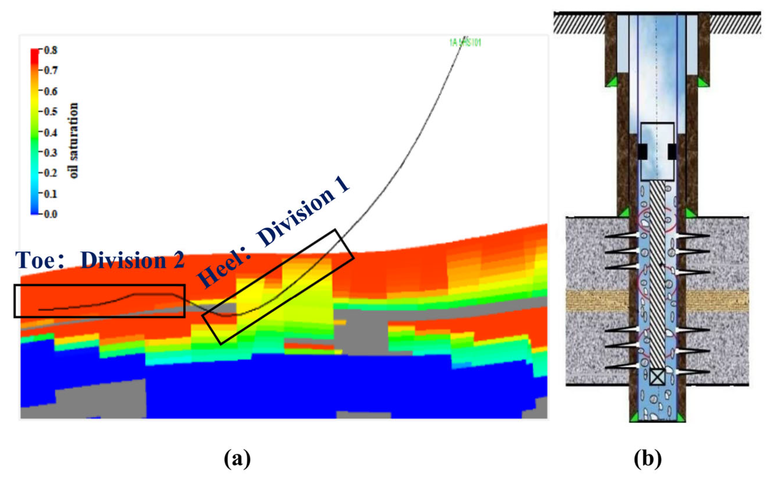
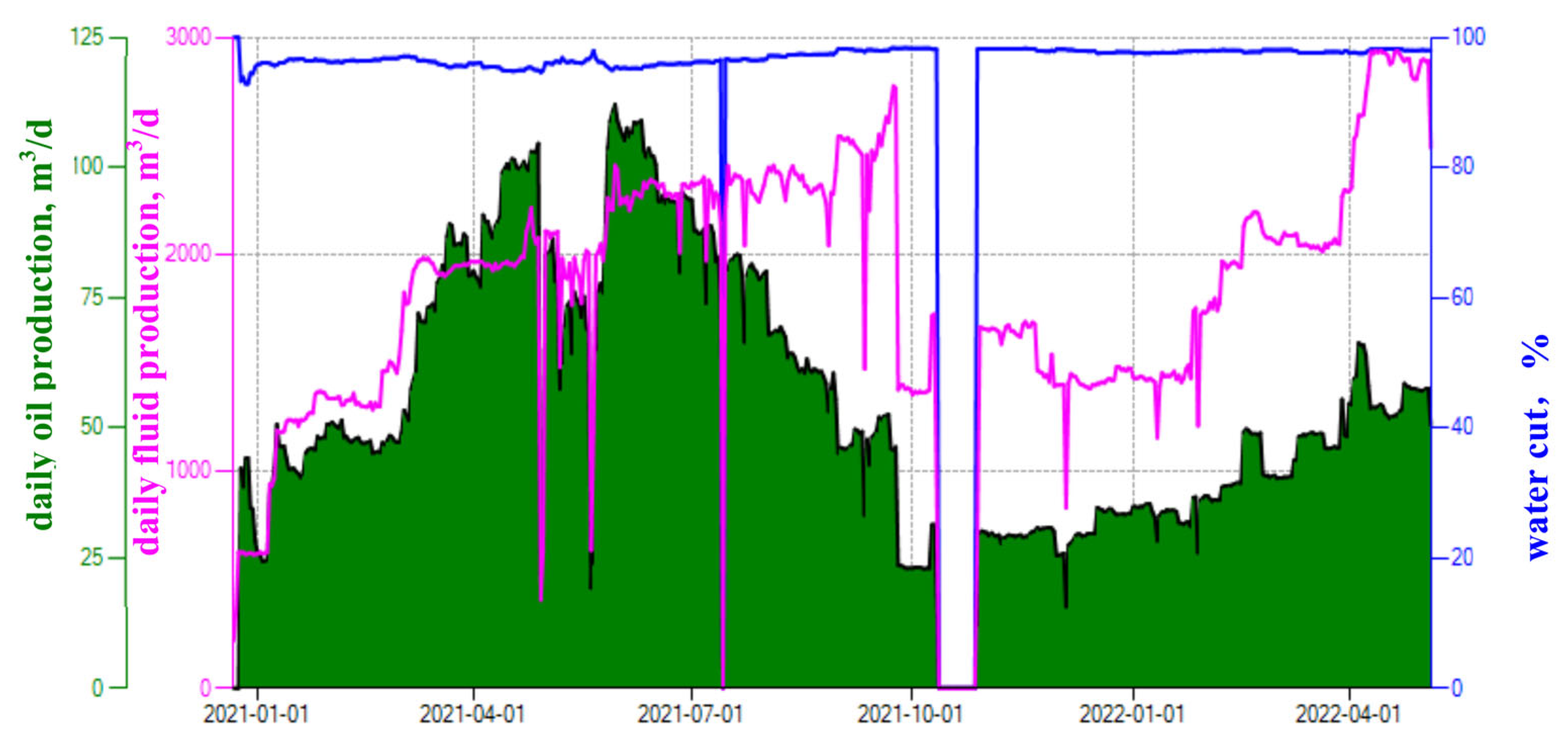
Water production rules based on static and dynamic data analysis
Taking the M2H well in X oilfield as an example, after the well was put online, as the water content gradually increased, the oil well gradually began to carry out frequent extractions. Before the measures, the daily liquid production was 1478 m3/d, the daily oil production was 37 m3/d, and the water content was 97.5%, as shown in Figure 3. Due to the long-term full-load operation of the oilfield treatment facilities, the oilfield is in a stage of limited-liquid production. It is urgent to carry out segmented-water-control measures for the horizontal section of the well, reduce the water content of the well, and improve the contribution level of the well’s production capacity.
In terms of reservoir drilling, there was a height difference of 2 m between the heel and the toe of the horizontal section of the well, and a mud interlayer was encountered during drilling in the middle. The logging results showed that the heel end was 1740–1853 m (113 m), with an average permeability of 75 mD, and the toe end was 1883–1992 m (109 m), with an average permeability of 1700 mD. The permeability difference between the heel end and the toe end reached 23, and a large permeability difference could easily cause uneven use of the horizontal section, as shown in Figure 4.
In terms of production dynamics, after the M2H well was put into operation, the bottom-hole flowing pressure remained stable with a production pressure difference of only 0.44 MPa. Compared with the historical production pressure difference of 4.0 MPa in adjacent wells, the comprehensive analysis suggested that there was a problem of low utilization of the tail end under lower production pressure differences. To this end, the horizontal section is segmented using mudstone or low-permeability layers as the boundary. The dynamic identification method of the reservoir is used to confirm that the following end is the main measure to tap potential. Mudstone can serve as a basis for segmentation.
(2)
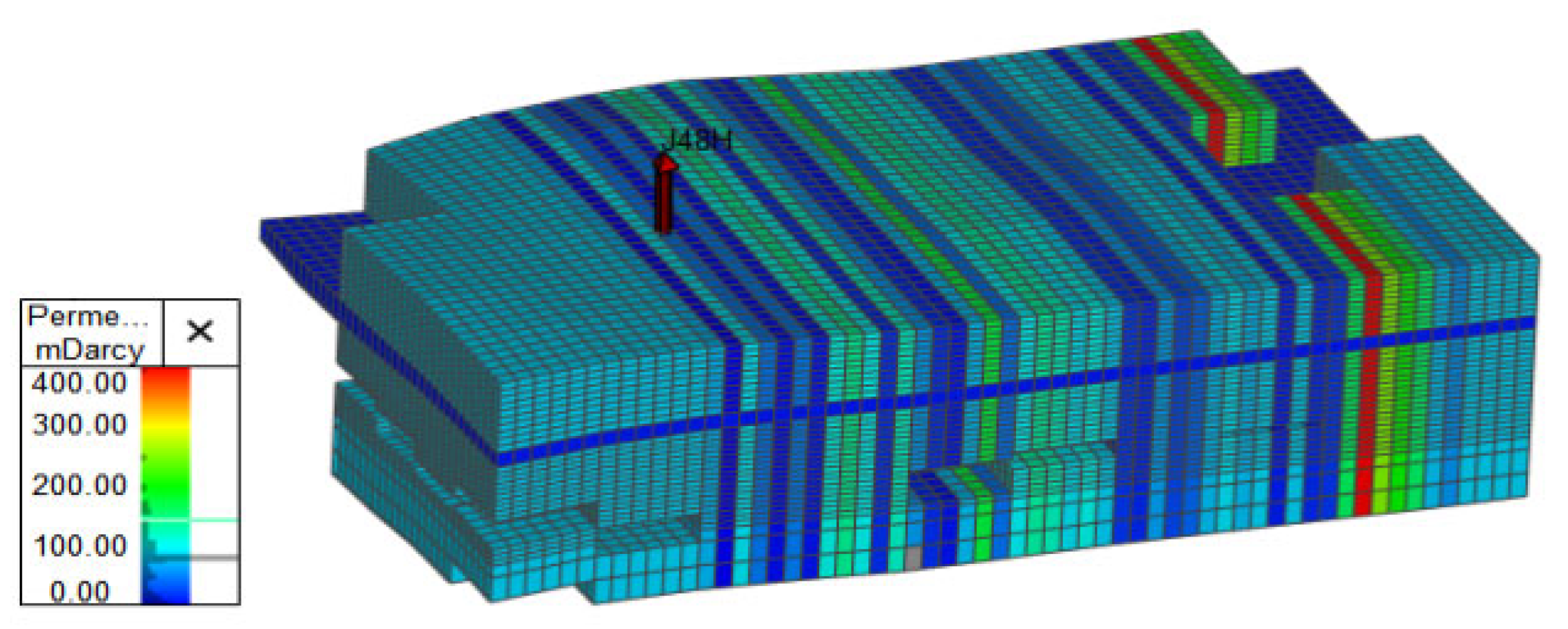
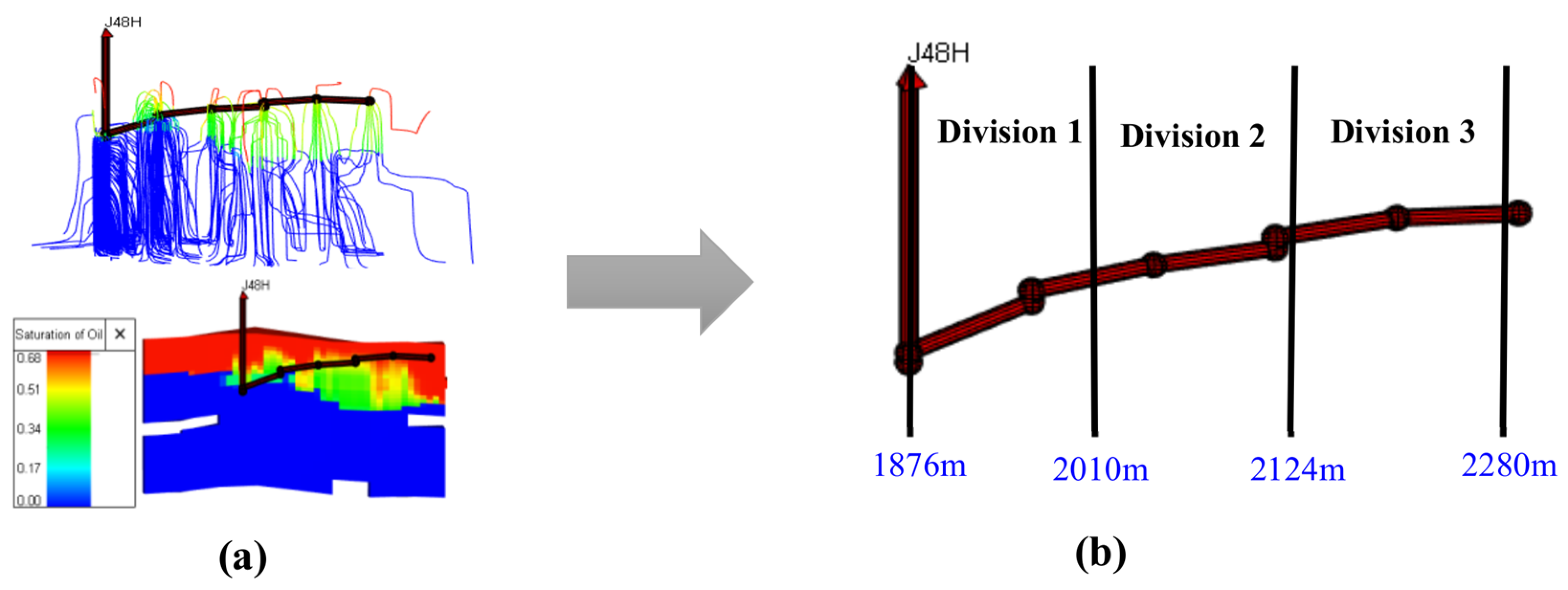
Water production rules based on the numerical simulation method
Taking the M1H well in X oilfield as an example, after the well was put online, it remained in a high-water-content state without a low-water-content period. During this period, the flow pressure remained basically stable. Before the producer stimulation measure was taken, the daily liquid production was 2900 m3/d, the daily oil production was 58 m3/d, and the water content was 98.0%, as shown in Figure 5. Dynamic production data showed that there was a water-flooded area in the early stages of the well being put online.
Through careful contrasting of neighboring wells, it was found that the distance between the M1H’s heel end and the old neighboring well was 150 m, and the water content of the old well before sidetracking was 97.0%. Moreover, due to the “heel–toe effect” of the horizontal flow, water is more likely to be released at the heel end. Therefore, it was preliminarily judged that there was a certain degree of water flooding at the heel end.
To further verify the dynamic understanding of geological reservoirs, a numerical simulation model was established based on the actual geological reservoir parameters of X oilfield. The relevant basic parameters are shown in Table 2.
The model was processed by local mesh refinement while retaining the physical property distribution characteristics of the original model. Then, based on the interpretation results of the well’s logging, the physical properties and distribution of the interlayer in the model were corrected. The result was that the heel end was below the interlayer and the toe end was above it. This model further restored the true structure, physical properties, and interlayer of the reservoir, ensuring the reliability of the model, as shown in Figure 6.
The purpose of historical fitting is to compare the simulated production data with the actual historical production data, obtain a model that can truly reflect the production laws of the reservoir, reduce the uncertainty of understanding underground reservoirs, and provide a more favorable basis for reservoir exploration and development. After the modeling was completed, historical data were imported into this simulation, which was a fixed-liquid-volume fitting. The fitting process mainly involves designing schemes based on the distribution range of interlayers and changes in reservoir permeability. Targeted historical fitting was carried out to achieve a better fitting effect in line with the understanding of underground oil reservoirs.
By combining the static and dynamic data of geological reservoirs and conducting fine reservoir numerical simulations [20], as shown in Figure 7, it was further proven that there was severe water release at the horizontal end section, but the degree of reserve utilization in the middle and the toe was relatively poor. Therefore, the horizontal well was designed to be mined in three sections, with the first section of the main water section closed and the second and third sections produced. Moreover, the second section was switched on and off depending on the production situation.
(3)
Establishment of sieving principles for target wells
Based on the above static and dynamic data analysis, to ensure the effectiveness of water control measures, reservoir understanding and well selection are crucial. According to the understanding that “high water content in an oilfield does not mean high water content in every well, and high water content in an oil well does not mean high water content in every part and direction of the horizontal section”, the main principles for selecting target wells in different compartments were the following: (1) production characteristics: high liquid volume, high water content, and small production pressure difference, resulting in different degrees of water flooding in high- and low-permeability sections; (2) water discharge characteristics: the degree of utilization in the horizontal section was uneven, and the water discharge mode was characterized by local flooding; (3) there was a large difference in permeability level between the heel and toe ends, and there was an elevation difference, preferably; (4) drilling through interlayers could effectively avoid lateral flow; (5) there was a certain amount of remaining recoverable reserves and a sufficient material foundation.

3.3. Implementation Method of Horizontal-Well Segmented Production Technology
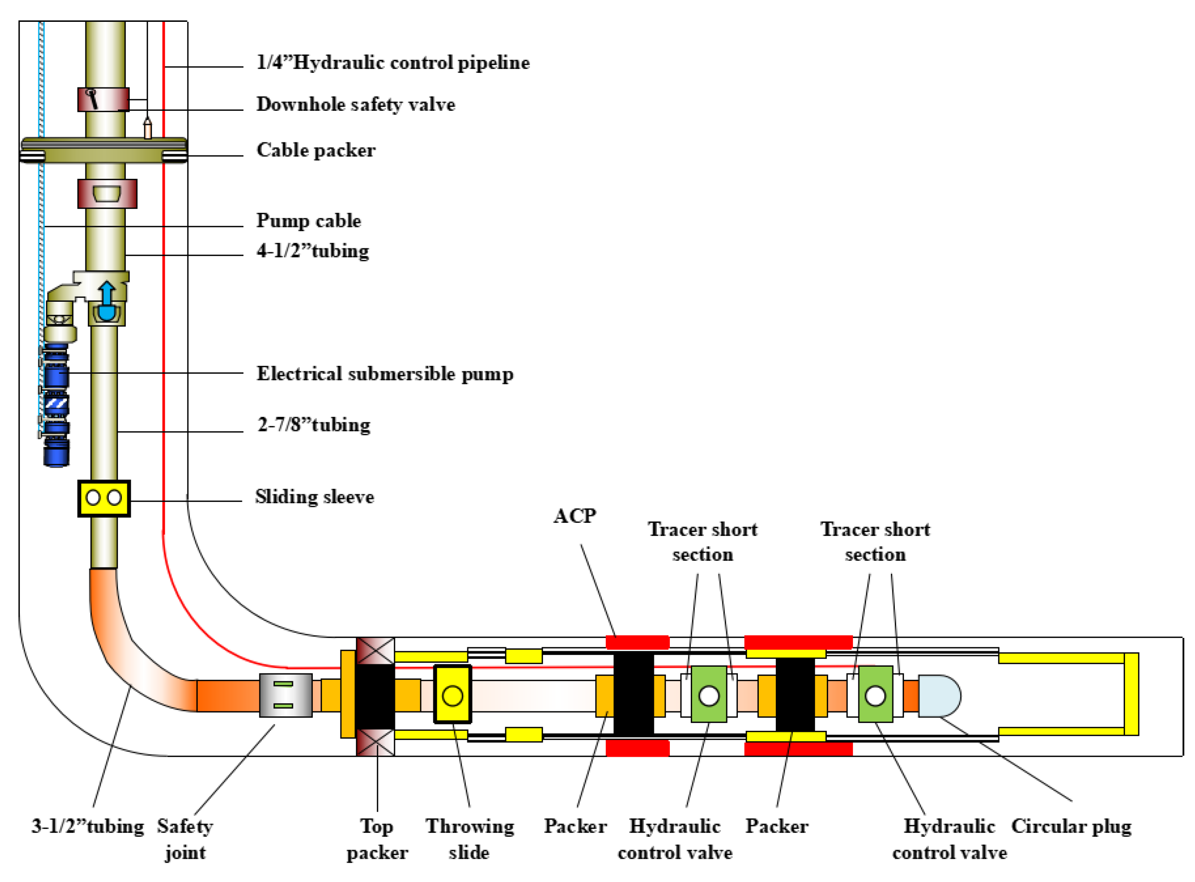
To improve the effectiveness of water-plugging measures, the implementation process was divided into three stages. Firstly, the horizontal section was manually segregated reasonably, combined with the reservoir engineering method and the drilling condition analysis, optimally based on interlayers or permeability discrepancies. Secondly, annulus chemical packer materials were squeezed between segments to effectively inhibit the fluid flow between the open hole and the screen. Moreover, the packers were used to seal between segments to effectively restrain the flow between the screen and the tubing, achieving the establishment of compartments. In the production process, the valves switched on the tubing could be independently controlled by a remotely adjustable method to achieve optimal production. The detailed information is presented in Figure 8.
(1)
Process of chemical sealing outside the tube
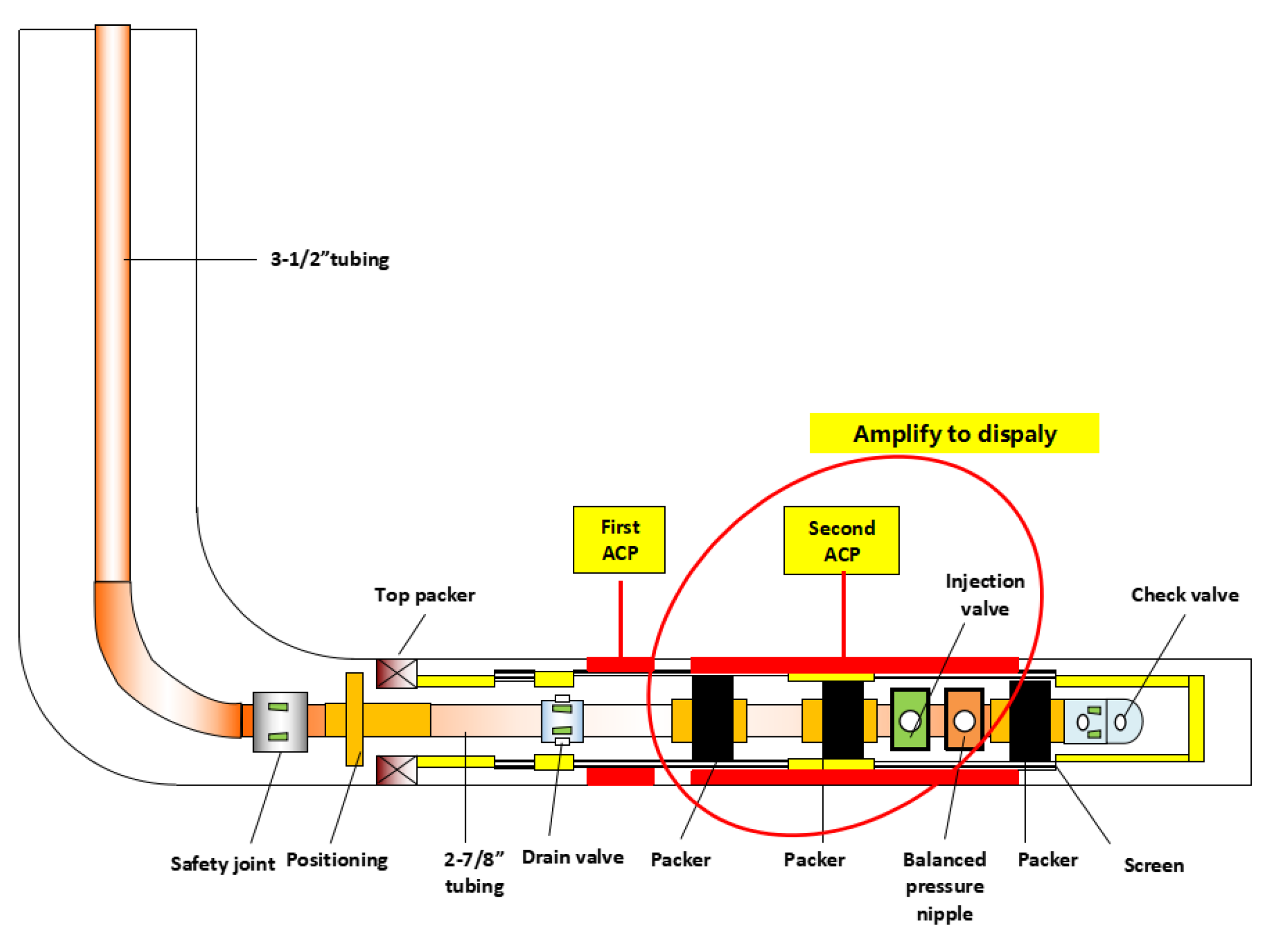
The sealing materials required for this process mainly consisted of thixotropic control agents, strength control agents, and other core components. They had high thixotropic properties, such as shear thinning and rapid structural recovery after shear rest. Compared with conventional sealing agents, ACP had a better “anti-collapse” effect and could effectively seal the outer annulus of the screen tube. The material had high thixotropic properties, such as shear thinning and rapid recovery of strength after rest. It was injected into the outer annulus of the pipe for effective sealing and suppression of axial water flow movement. The process string required for this process was mainly used to achieve the fixed-point injection function of ACP in the horizontal section, providing corresponding measures and methods for annular sealing. It mainly consisted of a single flow valve, an injection valve, a K344 packer, a positioning bypass, an oil drain valve, and a safety joint. The implementation process of this process mainly involved injecting the pipe column into the target position. By applying pressure inside the tubing, when the pressure difference between the inside and outside of the tubing reached 0.5 MPa, the K344 packer began to set, achieving the sealing of the injection valve and the upper and lower casing annuli. The pressure continued to rise, and the pressure difference reached 1.5~2 MPa. The injection valve was opened, allowing for injection into the target layer segment. The injection of the current layer was completed, and the pipe column was lifted for ACP solidification. After ACP solidification was completed, the pipe column was inserted into the injection layer for sealing inspection. The pipe column for the injection operation of the next layer was lifted, as shown in Figure 9. The injection string had the ability to achieve multiple rounds of fixed-point injection, with the features of simple sealing and unlocking and convenient homework.
(2)
Process of segmented production inside the tube
This process mainly consisted of two hydraulic control valves, one ball sliding sleeve, four tracer short joints, two Y341 pipeline packers (suitable for 5-1/2“ casing), 6” pipeline positioning seals, one 2.313“ sliding sleeve, one 216Y joint, one submersible electric pump, and 9-5/8” cable packers. The implementation principle of this process was mainly to insert the production string into the horizontal well screen pipe once, and after it was in place, to use oil pipes to pressure and seal the Y341 pipeline packer and cable packer, respectively. The sliding sleeve was opened, and the submersible pump was started for production. By using a 1/4“ liquid-control pipeline, the switch control of the generation layer and the water control of the target layer were achieved. Each tracer short section was equipped with a water-soluble tracer product. During the production process, through tracer testing, the contribution of oil and water in each section was recognized, guiding the layer switch. If the first stage of production was resumed, the submersible pump was turned off, the production plug was removed during wire operation, the ball-throwing slide sleeve was opened, the production plug was put in, and the submersible pump was started for production, as shown in Figure 10. This process had a single string insertion, making the operation convenient. The target layer was controlled on the ground. Through hydraulic control, it had excellent temperature resistance and high reliability, obtaining oil–water information through tracer monitoring, achieving integrated testing and control functions, and other advantages.

4. Implementation Effects of Horizontal-Well Segmented Production Technology in Bottom Water Reservoirs

4.1. Establishment of Evaluation Methods for Segmented Production Technology

Due to limited platform space, X oilfield has a long-term full-load operation of liquid processing capacity. At present, the standard for water plugging in oil wells does not include measures to increase oil production from other oil wells after lowering the well’s liquid level. Especially for the segmented extraction measures, some wells have a significant decrease in daily liquid production and water content after implementing the measures, but there is no clear evaluation method for the oil production effect [14]. In response to the above issues, two methods are proposed (net-water-content reduction and fixed production of liquid) to calculate the daily oil increase of single-well measures, in order to ensure a reasonable and reliable evaluation of the effectiveness of compartmental-water-control measures.
The calculation of daily oil increase using the net-water-content-reduction method is mainly defined as the difference between the corresponding pre-measure water content of the post-measure daily oil production and the post-measure daily liquid production, as shown in formula (1). Its physical meaning is the corresponding daily oil production under the condition of constant water content after reducing the daily liquid production of the oil well before implementing water-blocking measures. The difference between the daily oil production after implementing the measures and the above-mentioned oil increase is the increase in oil production. The calculation method is simple, as shown in Figure 11.
ΔQO = QOA − QLA × (1 − fwB)
In the formula, ΔQO is the increase in daily oil production, m3/d; QOA is the daily oil production after taking measures, m3/d; QLA is the daily liquid production after taking measures, m3/d; and fwB is the water cut before taking measures.
The calculation of daily oil increase using the method of fixed production of liquid mainly involves summing the daily oil production after the measures and the increase in oil production from other old wells by adding liquid and then deducting the daily oil production before the measures, as shown in formula (2). Its physical meaning is that the daily liquid production before and after the measures is the same. After the measures, other old wells were lifted due to the reduction in liquid production in the oil well. This increase in oil production is also the effect of water-blocking measures. Therefore, this method is more in line with the evaluation of the effectiveness of water-blocking measures in oilfields under limited-liquid conditions, as shown in Figure 12.
ΔQO = QOA + QOS − QOB
In the formula, ΔQO is the increase in daily oil production, m3/d; QOA is the daily oil production after taking measures, m3/d; QOS is the increase in oil production from other old wells by increasing liquid under the condition of maintaining a constant total daily liquid, m3/d; and QOB is the daily oil production before taking measures, m3/d.

4.2. Summary of Water Control and Oil Increase Effects for Segmented Production Technology

Through process innovation and column optimization, good on-site practices for horizontal-well subdivision and remote-controlled liquid-control process technology have been implemented, such as Table 3. Taking M1H and M2H as examples, after the implementation of the measures, M1H was divided into three sections as the first horizontal-well segmented pilot test well. After the measures were implemented, the toe potential section was opened for production. In the initial stage, the daily liquid production decreased from 2866 m3 to 414 m3, resulting in a 5.9-fold daily liquid production decrease. The water content decreased from 98.0% to 88.5%, i.e., by 9.5%, as shown in Figure 13. As of now, the effective period has reached 442 days. The second horizontal well, M2H, was divided into two sections for segmented and compartmentalized testing. After the measures were taken, the follow-up potential section was opened for production. Initially, the daily liquid production decreased from 1446 m3 to 205 m3, i.e., a 6.1-fold decrease. The water content decreased from 98.1% to 77.8%, i.e., a decrease of 20.3%. As of now, the effective period has reached 313 days. As shown in Table 2, the total liquid volume of the six wells mentioned above decreased by 6744 m3. Using the net-water-content-reduction method, the daily oil increase was calculated to be 185 m3, with an average daily oil increase of 31 m3 for a single well. The effect of oil increase and precipitation was significant.
The horizontal-well segmented production technology for strong-bottom-water reservoirs has significant advantages in the following three aspects: Firstly, it controls water and increases oil production. By controlling liquid production through horizontal-well segmented production, not only can the water content of ultra-high-water-cut oil wells be effectively reduced, but the daily liquid production of oil wells can also be greatly reduced by more than 1000 m3. Under conditions of full oilfield processing capacity and limited-liquid production in some oil wells, this approach provides liquid-volume space for other oil wells under liquid-limit conditions to increase liquid production. Secondly, it reduces energy conservation and consumption. The energy consumption of mechanical production wells in X Oilfield is high (accounting for 48% of the entire oilfield), making it difficult to control energy consumption costs. This technology effectively integrates energy conservation and carbon reduction with increased production and efficiency. The average energy consumption of a single well is reduced by 67%, which can reduce the energy consumption cost of mechanical production. Thirdly, it reduces liquid costs. As of now, the total daily production of 6744 m3 of liquid has been reduced in the six segmented well measures implemented in X Oilfield, greatly alleviating the burden of oilfield treatment and effectively reducing the cost of single-well water treatment, fundamentally achieving cost reduction and efficiency increase.
The focus of this technology is a potential oil-well tapping measure based on a clear understanding of various geological reservoir data in horizontal wells. The potential risk is that the ACP injection position may not be appropriate or the sealing quality after injection may be poor, which will have a certain negative impact on the effectiveness of the subdivision measure. At the same time, uncertainty arises from the incomplete understanding of geological reservoirs, which may lead to not achieving the expected results in segmented production. However, this uncertainty can be solved by trying to separate the production situation of each section and ultimately selecting the best section for production.

5. Conclusions

Horizontal-well segmented production technology does not require water testing, and the optimal production section can be chosen through segmented independent production, greatly improving the success rate of water-plugging measures in horizontal wells with bottom water reservoirs. This technology opens up a new mode for efficient development of horizontal wells in bottom water reservoirs and is planned to be widely promoted and applied to similar problems.
(1)
In response to the difficulty of stabilizing oil and controlling water in offshore strong-bottom-water reservoirs and the lack of economically effective methods for controlling water and stabilizing oil, directional-well layered production technology has been applied to horizontal wells in bottom water reservoirs, and an innovative technology for horizontal-well segmented production technology in offshore strong-bottom-water oilfields has been proposed.
(2)
By refining the implementation path of reservoir research and oil recovery technology, external chemical plugging and internal segmented extraction processes were developed, with functional advantages such as the following: no need for pulling strings, convenient operation, high reliability, and integration of dynamic tracking and compartment adjustment. These advantages greatly improve the success rate of water-blocking measures for horizontal wells in bottom water reservoirs.
(3)
Through the on-site practice of horizontal-well segmented production technology for offshore strong-bottom-water reservoirs, two evaluation methods were established (the net-water-content-reduction method and the method of fixed production of liquid) to calculate the daily oil increase of segmented measures, in order to ensure that the evaluation of the effectiveness of this technology was reasonable and reliable.
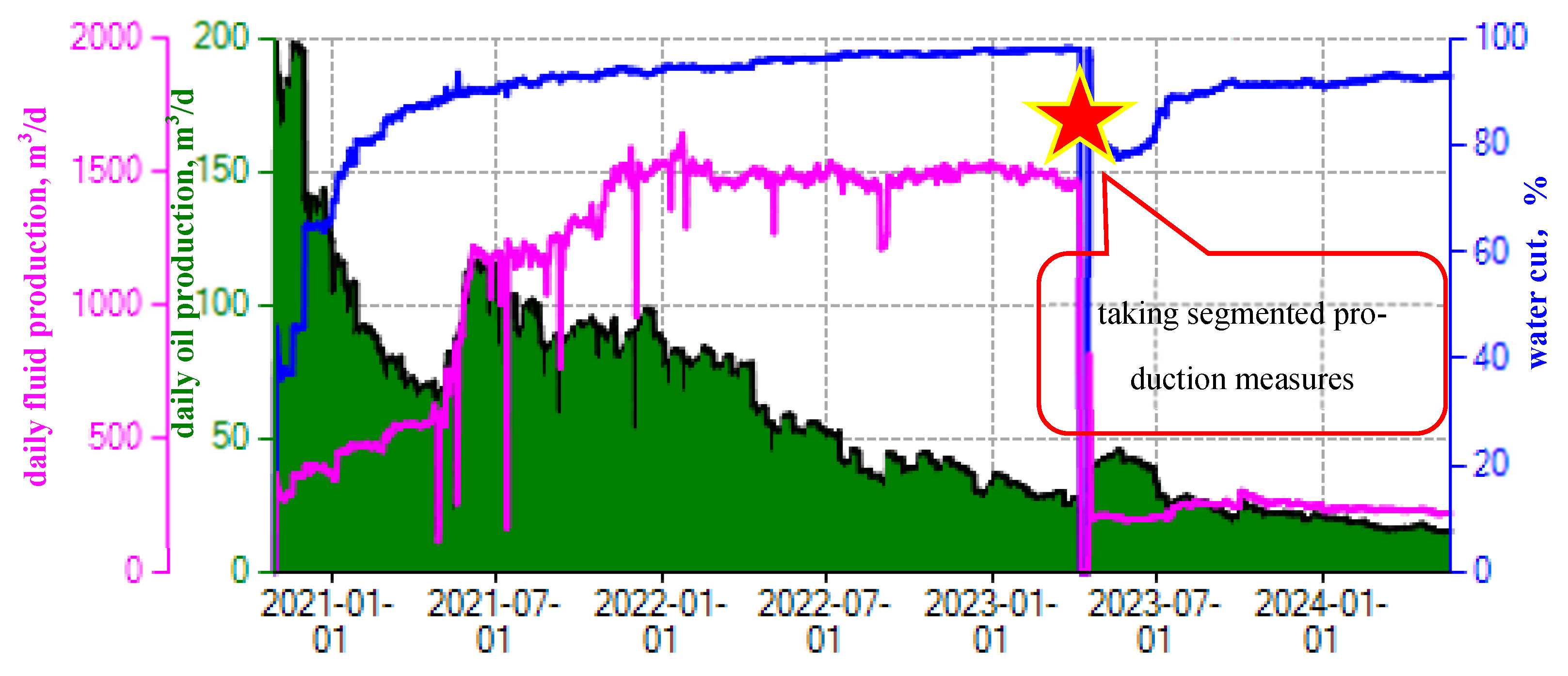
(4)
Up to now, this technology has been successfully applied in six wells, achieving an average reduction of 1124 m3 of daily liquid production per well, an increase of 31 m3 of oil per day, and an average decrease in water content of 5.6% in the early stages of the measures by using the net-water-content-reduction method. The traditional combined production mode in the horizontal section of the bottom water reservoir was transformed into a segmented and precise control mode, providing important technical support for controlling the bottom water ridge to achieve balanced production in the horizontal section and improving the degree of reserve utilization in the horizontal section.

Author Contributions

Conceptualization, D.Z. and F.L.; methodology, Y.L.; formal analysis, Z.Z.; data curation, H.L.; writing—original draft preparation, D.Z.; writing—review and editing, F.L.; project administration, Y.L. All authors have read and agreed to the published version of the manuscript.

Funding

This research was funded by the 14th Five-Year Plan of the major Science and Technology Project at CNOOC Ltd. (project number: KJGG2021-0501).

Data Availability Statement

The data that support the findings of this study are available from the corresponding author upon reasonable request. The key data, such as Table 3, are sourced from on-site measurement data. Currently, commercial flow meters are used in offshore oilfields, with a water content error of about 2%. The errors before and after the measures are consistent, so the data are detailed and reliable.

Acknowledgments

The authors acknowledge the technical support provided by Bohai Oilfield Research Institute in using the Eclipse software “ECL 2020.1”.

Conflicts of Interest

Authors Dong Zhang, Yanlai Li, Zongchao Zhang, Fenghui Li and Hongjie Liuwas employed by the company Tianjin Branch of CNOOC Ltd. The authors declare that the research was conducted in the absence of any commercial or financial relationships that could be construed as a potential conflict of interest.

References

  1. Jiang, X.; Sun, Z.B.; Li, G.L. Model for Predicting Horizontal Well Transient Productivity in the Bottom-Water Reservoir with Finite Water Bodies. J. Energies 2023, 16, 1952. [Google Scholar]
  2. Yao, D.Y.; Li, T.Y.; Wang, G.Y. A New Model for Evaluation of Horizontal Well in Bottom Water Reservoirs. J. Appl. Mech. Mater. 2013, 411–414, 486–491. [Google Scholar] [CrossRef]
  3. Li, T.Y.; Yao, D.Y.; Peng, T. Systematic Evaluation on Horizontal well Performance in Bottom Water Reservoir. J. Appl. Mech. Mater. 2013, 411–414, 3129–3133. [Google Scholar] [CrossRef]
  4. Ming, J.Z.; Dong, X.W.; Zhuang, Z. Study on Fluid Solid Coupling of Horizontal Wells in Bottom Water Sandstone Reservoir. J. Adv. Mater. Res. 2013, 827, 239–243. [Google Scholar]
  5. Zhang, C.; Gu, Z.; Cao, L. Effect of Pressure and Temperature Variation on Wax Precipitation in the Wellbore of Ultradeep Gas Condensate Reservoirs. SPE J. 2023, 29, 1–16. [Google Scholar] [CrossRef]
  6. Gang, Y.W.; Dong, Y.Y.; Ming, J. A Quick Evaluation Model for Horizontal Well Development in Bottom Water Reservoir. J. Adv. Mater. Res. 2011, 347–353, 398–402. [Google Scholar]
  7. Luo, W.; Zhou, Y.; Wang, X. A novel 3-D model for the water cresting in horizontal wells. J. Hydrodyn. Ser. B 2008, 20, 749–755. [Google Scholar] [CrossRef]
  8. Zhang, N.; An, Y.S.; Huang, R.S. Research on Production Performance Prediction Model of Horizontal Wells Completed with AICDs in Bottom Water Reservoirs. J. Energies 2023, 16, 2602. [Google Scholar] [CrossRef]
  9. Shang, B.; Han, X.; Li, S. Research of water control technology for horizontal wells in water-driven reservoirs. J. Adv. Geo-Energy Res. 2018, 2, 210–217. [Google Scholar] [CrossRef]
  10. Wang, J.; Liu, H.; Liu, Y. Mechanism and sensitivity analysis of an inflow control devices (ICDs) for reducing water production in heterogeneous oil reservoir with bottom water. J. Pet. Sci. Eng. 2016, 146, 971–982. [Google Scholar] [CrossRef]
  11. Shan, Y.W.; Zhang, X. The Research for Delaying the Bottom Water Coning in Horizontal Wells Application Balance Screen Pipe. J. Adv. Mater. Res. 2013, 734–737, 1480–1483. [Google Scholar] [CrossRef]
  12. Li, P.F.; Tang, H.; Yang, X.M. Laboratory Evaluation on the Water Flooding Characteristics in Bottom Water Reservoir Containing Interbeds. J. ACS Omega 2023, 8, 42409–42416. [Google Scholar]
  13. Liu, C.; Li, K.; Tian, X. Experimental studies on production performance of oil reservoirs with bottom water. J. Pet. Sci. Eng. 2018, 172, 527–537. [Google Scholar] [CrossRef]
  14. Zheng, Q.; Liu, H.; Li, F. Study on Water Breakthrough Regularity and Influencing Factors of Horizontal Wells in a Heterogeneous Reservoir With Bottom Water. J. Pet. Sci. Technol. 2013, 31, 803–811. [Google Scholar] [CrossRef]
  15. Zhang, C.; Xi, L.; Wu, P. A novel system for reducing CO2-crude oil minimum miscibility pressure with CO2-soluble surfactants. J Fuel 2020, 281, 118690. [Google Scholar] [CrossRef]
  16. Li, F.L.; Yue, A.X.; Zhang, J.L. Experimental Research for Breakthrough Position of Horizontal Wells in Reservoirs with Bottom Water. J. Adv. Mater. Res. 2012, 524–527, 1232–1235. [Google Scholar] [CrossRef]
  17. Sun, G.; Zhang, J.; Lei, Y. Numerical Simulation Study for Water Breakthrough Law of Horizontal Well in Edge Water Reservoir. J. Adv. Pet. Explor. Dev. 2016, 11, 50–54. [Google Scholar]
  18. Zhang, C.; Wu, P.; Li, Z. Ethanol enhanced anionic surfactant solubility in CO2 and CO2 foam stability: MD simulation and experimental investigations. J Fuel 2020, 267, 117162. [Google Scholar] [CrossRef]
  19. Wu, D.X.; Wang, N.Y.; Wang, H.R. Research on Horizontal Well Inhibiting Water Coning and Tapping the Potential of Remaining Oil. J. Appl. Mech. Mater. 2014, 527, 57–64. [Google Scholar] [CrossRef]
  20. Zhen, Z.H.; Chao, R.Y.; Ping, A.F. Remaining oil distribution in bottom water reservoir of Lin 2–6 fault-block in Huimin depression and potential tapping in horizontal well. J. Min. Sci. Technol. 2008, 19, 102–107. [Google Scholar]
Figure 1. Production characteristics of strong-bottom-water reservoirs. (a) Typical well production curve; (b) proportion of oil wells in each water cut stage.
Processes 12 01142 g001
Figure 2. Origin of segmented production technology for horizontal wells. (a) Mathematical model realization of horizontal wells’ remaining oil distribution; (b) directional-well separate production technology.
Processes 12 01142 g002
Figure 3. Production status of ultra-high-water-cut M2H well before taking measures.
Processes 12 01142 g003
Figure 4. Drilling condition analysis.
Processes 12 01142 g004
Figure 5. Production status of ultra-high-water-cut M1H well before taking measures.
Processes 12 01142 g005
Figure 6. Permeability distribution of three-dimensional reservoir model.
Processes 12 01142 g006
Figure 7. Numerical simulation method analysis. (a) Residual oil distribution analysis; (b) results of horizontal-well segmentation.
Processes 12 01142 g007
Figure 8. Flow chart of the introduction of the technique.
Processes 12 01142 g008
Figure 9. ACP injection process diagram.
Processes 12 01142 g009
Figure 10. Diagram of the production string.
Processes 12 01142 g010
Figure 11. Calculation of daily oil increase using the net-water-content-reduction method.
Processes 12 01142 g011
Figure 12. Calculation of daily oil increase using the method of fixed production of liquid.
Processes 12 01142 g012
Figure 13. Production status of ultra-high-water-cut M2H well after taking measures.
Processes 12 01142 g013
Table 1. Main parameters of the oil reservoir.
Stratigraphic HorizonOil Column Height,
m
Permeability,
mD
Crude Oil Viscosity,
mPa·s
Reserve Proportion,
%
N1mu155793200–45037
N1mL12412850–15023
N1gⅢ1016071~3040
Superscript represents different oil formations of the same layer.
Table 2. Basic parameters of the numerical model.
Oil viscosity
mPa·s
Oil density
g/cm3
Oil layer thickness
m
Vertical-to-
horizontal
permeability ratio
Water avoidance height mBoundary
conditions
300.89200.116~18Carte-Tracy model
Horizontal -well length
m
Porosity
%
Permeability
10−3μm2
Model dimensionGrid size
m
Location of water bodies
48025800(av)80 × 40 × 4025 × 25 × 1bottom
Table 3. Comparison of production conditions using well segmented production technology.
Well NoDaily Oil Production, m3Daily Liquid Production, m3Water Cut, %Net Oil Increase, m3
Before Taking MeasuresAfter Taking MeasuresBefore Taking MeasuresAfter Taking MeasuresLiquid Decrease Factor Before Taking MeasuresAfter Taking MeasuresWater Cut DecreaseNet-Water-Content-Reduction Method
M1H58 48 2866 414 5.9 98.0 88.5 9.5 39
M2H27 46 1446 205 6.1 98.1 77.8 20.3 42
M3H54 66 1808 1516 0.2 97.0 95.6 1.4 21
M4H35 46 1091 689 0.6 96.8 93.4 3.4 23
M514 54 1124 77 13.6 98.8 29.8 69.0 53
M6H41 19 1952 642 2.0 97.9 97.0 0.9 6
Sub22927910,2863542/97.892.15.6185
Disclaimer/Publisher’s Note: The statements, opinions and data contained in all publications are solely those of the individual author(s) and contributor(s) and not of MDPI and/or the editor(s). MDPI and/or the editor(s) disclaim responsibility for any injury to people or property resulting from any ideas, methods, instructions or products referred to in the content.

