Article

Analysis of the Effects of Structural Parameters on the Thermal Performance and System Stability of Ventilation Air Methane-Fueled Reverse-Flow Oxidation Reactors

by
Zhigang Zhang
1,
Jiaze Yang
2,
Shanshan Shao
3,
Tao Cai
2,
Aikun Tang
2,* and
Lu Xiao
1
1
State Key Laboratory of Coal Mine Disaster Prevention and Control, Chongqing 400039, China
2
School of Energy and Power Engineering, Jiangsu University, Zhenjiang 212013, China
3
School of Automotive and Traffic Engineering, Jiangsu University, Zhenjiang 212013, China
*
Author to whom correspondence should be addressed.
Processes 2024, 12(6), 1193; https://doi.org/10.3390/pr12061193
Submission received: 10 May 2024 / Revised: 30 May 2024 / Accepted: 31 May 2024 / Published: 11 June 2024
(This article belongs to the Section Energy Systems)

Abstract

:
Ventilation air methane (VAM) from coal mining is a low-grade energy source that can be used in combustion systems to tackle the energy crisis. This work presents a numerical analysis of the thermal and stabilization performance of a VAM-fueled thermal reversal reactor with three fixed beds. The effects of the combustion chamber/regenerator height ratio (β), heat storage materials, and porosity on the oxidation characteristics are evaluated in detail. It is shown that the regenerator temperature tends to vary monotonically with β due to the coupling effect of the gas residence time and heat transfer intensity. The optimal β is determined to be 4/6, above which the system may destabilize. Furthermore, it is found that regardless of the methane volume fraction, the regenerator with mullite inserted has the highest temperature among the heat storage materials investigated. In contrast, the temperature gradually decreases and the system becomes unstable as SiC is adopted, signifying the importance of choosing proper thermal diffusivity. Further analysis reveals that the porosity of the heat storage materials has little effect on the system stability. Decreasing the porosity can effectively reduce the oscillation amplitude of the regenerator temperature, but it also results in greater pressure losses.

1. Introduction

Ventilation air methane (VAM), mainly composed of methane, is a low-grade energy source that is derived from coal mining. As the second most abundant greenhouse gas, methane has 25 times the global warming potential (GWP) of carbon dioxide and is 7 times more potent in destroying the ozone layer [1,2,3]. Methane from VAM discharged to the atmosphere accounts for 61% of the total emissions worldwide, representing not just a waste of energy but also a promoter of climate change. Therefore, it is important and meaningful to reuse VAM [4]. Even though the heating value of VAM is relatively low, proper utilization of this fuel with effective combustion technologies contributes to tackling climate change and the energy crisis, given the large quantities involved [5,6]. However, VAM’s highly efficient utilization is challenging due to the low methane concentration, which poses difficulties in combustion systems.
To date, there are two types of combustion technologies that utilize VAM: The first method is to apply VAM to internal combustion engines [7], gas turbine engines [8], and pulverized coal-fired power stations [5,9], aiming to partially replace air as an oxidizer and, thus, reduce the main fuel consumption. However, this approach is limited by equipment and regional conditions, and it cannot be used on a large scale. The other method is to use VAM as a primary fuel by using thermal reversal combustion technology. Two typical examples of this are thermal flow-reversal reactors (TFRRs) [10,11] and catalytic flow-reversal reactors (CFRRs) [12,13,14]. Both systems are operated with the gas flow periodically reversed, and they incorporate heat storage materials with porous media. The purpose of including porous media is to ensure that the reactor maintains a sufficiently high temperature, thereby ensuring the successful implementation of ultra-lean methane combustion.
The major difference between these two systems is in whether or not a catalyst is applied. In CFRRs, the implementation of a catalyst can maintain the stable operation of the heat storage system, even when the methane concentration is as low as 0.06 vol.% [15]. Meanwhile, it can also significantly reduce the oxidation temperature, thereby suppressing the formation of the pollutants, NOx, CO, and SO2. However, most catalysts adopted are noble-metal-based and are not only expensive but also have problems such as high toxicity, high-temperature inactivation, and poor stability, leading to low operational efficiency [16,17]. In contrast, TFRRs are better options for effective VAM oxidation. Their features include being highly economical and reliable, especially when the methane concentration exceeds 0.4 vol.%, as demonstrated in the previous work by Gosiewski et al. [16]. Gao et al. [18,19] experimentally confirmed that applying packed honeycomb ceramics to the heat extraction region contributed to enhancing the heat transfer of the heat exchanger.
Extensive studies pertaining to VAM-fueled TFRRs have been conducted by a number of scholars, with emphasis on reaction mechanism reduction [20,21,22], mathematical modeling [23,24], heat recovery [25,26,27], and operating parameter optimization [28,29]. In practice, there are significant fluctuations in the gas concentration and flow rate due to the extraction process or the excavation area. This will lead to the occurrence of system instability, seriously reducing the oxidation efficiency of the device. Therefore, enhancing the operational stability performance of the device has received wide attention. For instance, Lan et al. [28] numerically illustrated that, during the thermal storage oxidation process of ventilation air gas, increasing the reactor channel length increased the maximum temperature significantly but led to a drop in the minimum feed concentration at which the system’s autothermal stable operation could be sustained. Chen et al. [30] numerically investigated the effect of periodic fluctuations in gas concentration on the oxidation behavior in a methane thermal reversal reactor. It was shown that the unstable combustion was caused by the inhomogeneity of the methane input, and the stability of the system could be enhanced by rationally adjusting the phase between the positive and negative cycles. Mao et al. [31] demonstrated that combustion instability was more prone to occur in cellular ceramic packing due to the lack of a mass dispersion effect, and the occurrence probability of this phenomenon was increased under dilution conditions. A follow-up work conducted by the same research group [32] carried out a comprehensive investigation of the feed methane concentration, valve opening ratio, and switching time’s impact on combustion stability, temperature asymmetry, and nonuniformity. It was found that adjusting the unequal semi-cycle switching time and flow mass redistribution was beneficial for improving temperature asymmetry and nonuniformity.
Marín et al. [33] numerically discussed the impacts of different thermal recovery strategies on oxidation performance in reverse-flow reactors. It was demonstrated that the system stability and thermal cycling efficiency can be expanded by placing the exhaust fan on the regenerator outlet and not recirculating the fresh gases into the reactor. Shi et al. [34] pointed out that embedding a heat exchanger to capture the high temperature of the regenerator can improve the asymmetry and achieve heat recovery efficiency of up to 61.72%. These results reveal that the negative effect of operating conditions and improper heat extraction forms is critical to the heat asymmetry and inhomogeneity of the reactor. Litto et al. [35] conducted a parametric study on a counterflow reactor and focused on the effects of the reactor diameter, the thermal mass of the regenerator, and its thermal conductivity on the operating characteristics of the device. The results indicated that, as the reactor diameter was increased, the effect of heat loss on the operating temperature was weakened, whereas the axial centerline temperature was increased significantly. Compared with thermal conductivity, the thermal mass had a more significant impact on the stability of the operating temperature, and a larger thermal mass was associated with a higher reactor temperature. Wang et al. [36] simulated the thermal stress distribution of honeycomb ceramic regenerators using CFX 15.0 software. It was found that severe temperature changes caused large thermal shocks, and the thermal stress increased with the increase in porosity. Rao et al. [37] assessed the oxidation performance of a thermal countercurrent reactor with basalt fiber bundles as the heat storage materials. It was numerically confirmed that the thermal counterflow reactor had better exhaust air treatment performance. Under the same operating conditions, the pressure loss of the basalt fiber bundle TFRR was reduced by 79.71%, and the waste heat economic benefit was 2.5 times that of the honeycomb ceramic TFRR.
Furthermore, the system stability is also dramatically affected by the inner structure of the thermal reversal reactor. Zazhigalov et al. [38] numerically reported that compared to reactors with axial gas feeding arrangements, a reactor with side feedings was associated with lower heat generation, which led to lower thermal stability and a 20% decrease in the maximum cycle duration. Kushwaha et al. [39] discussed the effects of heat storage materials on temperature distribution, heat accumulation rate, and combustor stability. It was shown that the temperature profiles were greatly impacted by the packing type, with the metal-type monolith having the smallest radical gradients and lowest pressure loss due to its high porosity. In contrast, the ceramic monoliths were associated with a higher thermal mass and, thus, better stability. Mei et al. [40] conducted Reynolds-averaged Navier–Stokes (RANS) equation simulations on a methane/air-fueled reverse-flow catalytic reactor and pointed out that the working performance of the monolith reactor was superior to that of the single-channel reactor.
Previous studies have revealed that, compared to the optimization of operational parameters and heat recovery strategies, the structural design of thermal reversal reactors tends to have a more pronounced effect on the system stability. To the best of the authors’ knowledge, most studies pertaining to VAM’s heat storage and oxidation are mainly focused on systems with two packed beds. Meanwhile, there are only several studies discussing the thermal destabilization characteristics and generation mechanisms. Given the wide practical applications of systems with three packed beds, this work presents a numerical analysis of the effects of reactor structure, heat storage materials, and porosity on the stability of VAM-fueled thermal reversal reactors, aiming to identify thermal destabilization mechanisms and propose possible enhancement strategies. The results obtained can provide a reference for the design and optimization of a thermal reversal oxidation reactor for the maximization of the system’s stability.

2. Numerical Model

2.1. Geometric Model of the Computational Domain

Figure 1a illustrates the geometric model of the computational domain; it is mainly composed of a combustion chamber, regenerators, and inlet/outlet pipes. The overall geometry of the reactor is 3000 × 700 × 2700 mm. The detailed geometry of the individual parts can be seen in Figure 1b. Considering that the honeycomb size is much smaller than that of the oxidation system, the filling region in the regenerator can be considered to be a uniform porous medium.
The whole cycle of this thermal reversal oxidation system consists of three stages, with each lasting 90 s, as listed in Table 1. In Stage I, the VAM mixture is introduced to Regenerator 1 and oxidized in the combustion chamber, and the resulting high-temperature exhaust gases are expelled from Regenerator 2. Meanwhile, the air-sweep gas is pumped into Regenerator 3 to deplete any remaining methane. In Stage II, Regenerator 2 acts as the inhaler, and the exhaust gases flow out from Regenerator 3. In Stage III, the inhaler becomes Regenerator 3, and the high-temperature gases are removed from Regenerator 1.

2.2. Numerical Scheme

The oxidation process of VAM in a thermal reversal reactor involves heat conduction, convection, radiation, chemical reactions, etc. For simplicity, the following assumptions were made to reduce the complexity and cost of the simulation: (1) VAM is composed of methane and air, which can be regarded as an ideal gas. (2) The porous medium is optically thick. (3) Honeycomb ceramics have a large specific surface area, leading to a sufficiently large convective heat transfer coefficient between gas and solid. Thus, a local heat balance is assumed between gas and solid. (4) The gas radiation is neglected. Based on the above assumptions, the governing equations pertaining to the physical/chemical processes are as follows:
Continuity equation:
ρ g t + ( ρ g v ) = 0 ,
Momentum equation:
t ( ρ g v ) + ( ρ g v ) = p + ( τ ¯ ) + ρ g g + S i ,
S i = ( μ α v i + C 2 1 2 ρ g | v | v i ) ,
where S i and v i are the momentum sources and the velocity in the i direction, respectively; μ denotes the dynamic viscosity; and α and C 2 are the viscous and inertial drag coefficients, respectively, which can be calculated via Ergun equations as follows:
α = D p 2 150 ε 2 ( 1 ε ) 2 ,
C 2 = 3.5 D p ( 1 ε ) ε 3 ,
where D p and ε are the equivalent diameter and porosity, respectively.
Species transport equation:
ε t ( ρ g Y i ) + ( ρ g v Y i ) = ( ε ρ g D i ,   m Y i ) + R i ,
Gas energy equation:
ε ρ g c p ,   g T g t + ρ g c p ,   g v T g = ( ε k g T g ) h a v ( T g T s ) + ε i = 1 N ( Δ H R ) i R i ,
Solis energy equation:
( 1 ε ) t ( ρ s c p , s T s ) = ( ( 1 ε ) k s T s ) + h a v ( T g T s ) ,
Ideal gas equation:
p M g = ρ g R T g ,
where ρ g , k g , c p ,   g , and T g are the density, thermal conductivity, heat capacity, and temperature of the gas, respectively; v is the velocity vector; g is the acceleration of gravity; t is time; p is pressure; Ri is the net generation rate of species i.
Commercial computational fluid dynamics software (Fluent 2020R2) was applied to solve the methane oxidation process. It was calculated that the maximum Reynolds number under cold operating conditions is 117,422.9; thus, a turbulent flow with a realizable k-ε model was applied. The convection term used the second-order upwind formula, the diffusion term adopted the central difference method, and the pressure–velocity correction used the PISO format. The non-stationary terms were in a first-order implicit format. During all numerical calculations, the time step was set to 1 s. In view of the influence of the combustion reaction on flow, all residual values were based on the energy term and were set to 10−6. The mixture was considered to be an incompressible ideal gas, whose specific heat capacity was calculated by the mixing law, while the thermal conductivity was determined by the ideal gas mixing law. The specific heat of each species was computed by the piecewise polynomial method.
During the simulation, the gas flow direction was changed by varying the boundary conditions of the inlets and outlets. This was achieved by combining the Fluent TUI command and event function. In this work, a two-step reaction mechanism is used to describe the VAM combustion in a honeycomb ceramic reactor, which has been demonstrated to be quite effective in revealing such phenomena. The kinetic parameters of the methane mechanism adopted are summarized in Table 2.
The boundary conditions were set as follows: A uniform velocity profile with given mass fractions of each species was imposed on the combustor inlet at ambient temperature and pressure. The combustor outlet was set to the pressure outlet conditions. The heat loss (q) from the external walls of the reactor involves radiation and convection heat transfer, which can be written as the following equation:
q = h n ( T w T ) + ε w σ b ( T w 4 T 4 ) ,
where h n is the convective heat transfer coefficient with a value of 5 W/(m−2·K), T w is the external wall temperature, T represents the ambient temperature, ε w is the wall emissivity, and σ b is the Stefan–Boltzmann constant.

2.3. Description of the Critical Evaluation Indices

To effectively evaluate the thermal performance of the regenerator during the operation process, we introduced three non-dimensional parameters, i.e., heat storage efficiency, heat release efficiency, and methane conversion rate. Of these, the heat storage ratio ( η a ) refers to the proportion of heat absorbed by the regenerator to that carried by the exhausted gases. The heat release ratio ( η r ) is defined as the proportion of preheated heat to that absorbed by the regenerator.
η a = c s m s Δ T S c g , h q m , h τ Δ T g , h × 100 % ,
η r = c g , c q m , c τ Δ T g , c c s m s Δ T S × 100 % ,
where c s , m s , and Δ T S are the heat capacity, mass, and temperature difference of the regenerator, respectively; Δ T S , q m , h , and Δ T g , h are the mass flow rate, mass, and temperature difference of the exhaust gases, respectively; c g , c , q m , c , and Δ T g , c are the heat capacity, mass flow rate, and temperature difference of the mixture, respectively; τ denotes the operation time.
The methane conversion rate ( η b ) is defined as the ratio of the methane flow rate consumed during the combustion process to the total methane supplied to the combustor inlet.
η b = C in   Q in   C out   Q out   C in   Q in   × 100 % ,
where C in   and C out   are methane volume fractions at the inlet and outlet, respectively, while Q in   and Q out   are the gas flow rate at the inlet and outlet, respectively.

2.4. Mesh Independence Analysis

A mesh independence analysis was also conducted to achieve accurate results with an acceptable computational cost. The software ICEM 2020R2 was applied to generate the grids. Figure 2 compares the temporal temperature of the regenerator on the top central point with five different mesh resolutions, where the gas flow rate (Qin) is 1350 m3/h, the methane volume fraction (Cin) is 0.72%, and the switching time (tc) is 90 s. As can be seen from this figure, the temperature with the maximum grid size of 35 mm is much higher compared to the other cases. However, further decreasing the maximum grid size to 20 mm, corresponding to a total grid number of 567,648, is shown to play a negligible role in the temperature profiles as compared to the finest mesh. Thus, the second-finest mesh can satisfy the calculation requirements and, thus, can be applied during simulations.

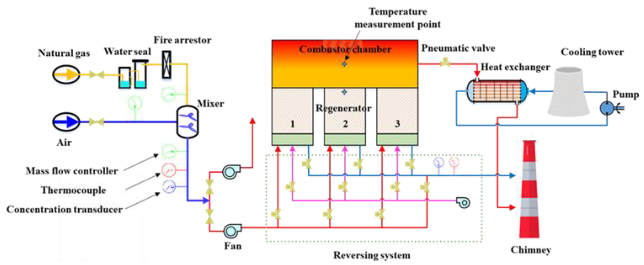
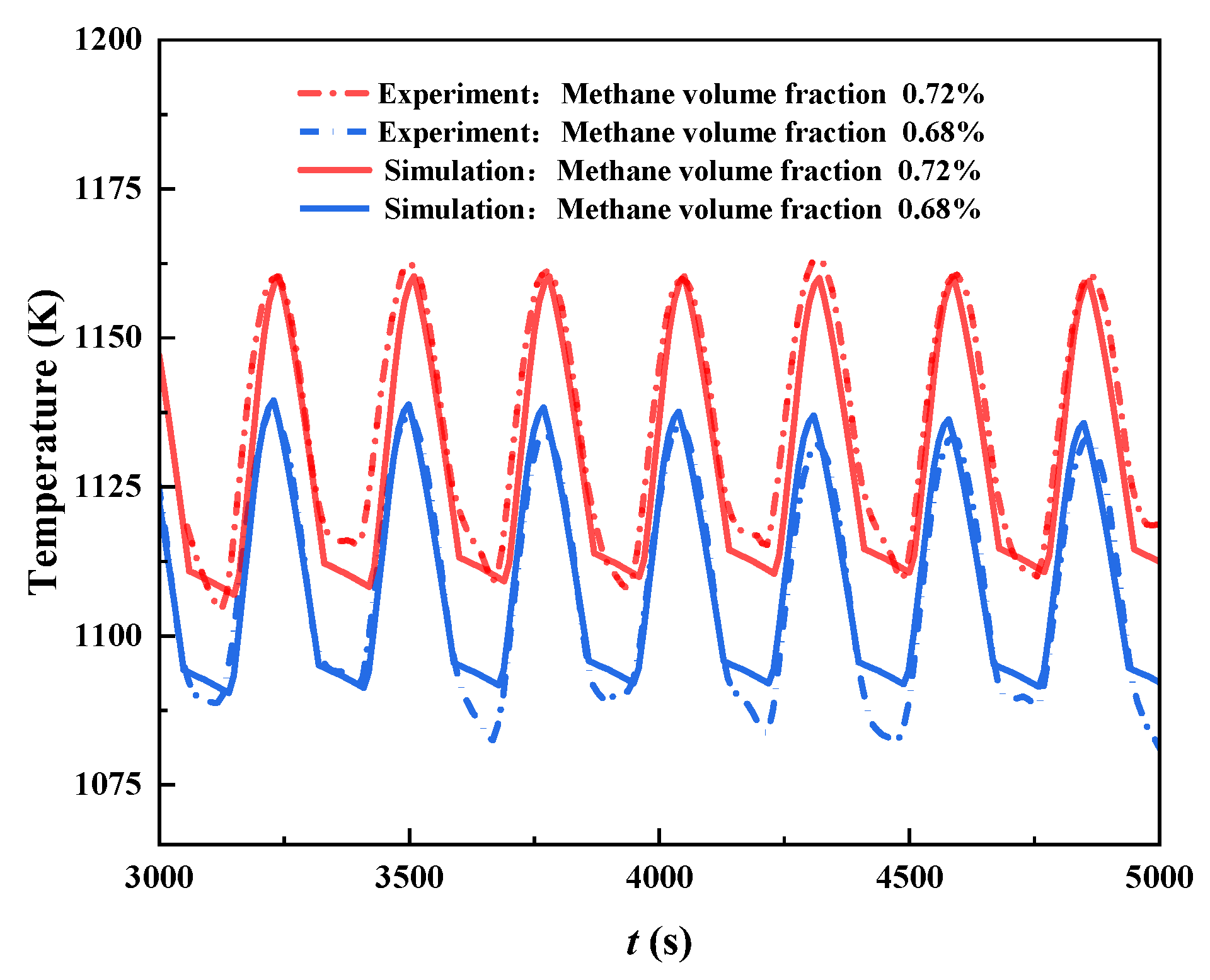
2.5. Model Validation

To demonstrate the accuracy of the established computational model, the numerically calculated results were compared with the experimental data when Qin = 1350 m3/h and tc = 90 s. Figure 3 shows the schematic diagram of the test platform for VAM heat storage and oxidation. It is mainly composed of a gas supply system, a gas switching system, a stationary oxidation bed, and a heat exchanger. In the gas supply system, the natural gas and air are mixed to mimic VAM during the coal mining process. Meanwhile, the methane concentration detector (model: KG9701B, accuracy: ±2.1%) is installed after the mixer. Concerning the switching system, seven pneumatic valves are used to periodically change the direction of fresh gas flow into the regenerator. As the core part of the experiment, the stationary oxidation bed contains three regenerators and one combustion chamber, where the chemical reaction of VAM takes place.
Multi-thermocouples (model: WRM241B, accuracy: ±0.75%) were placed in the combustion chamber and regenerator in the axial direction. For brevity and comparison, we only evaluated the central temperature point of the combustion chamber and the top temperature point of the regenerator to characterize the operating performance of the system, as shown in Figure 3. Before performing the experiment, the oxidized bed was first externally heated by diesel combustion. Once the temperature of the combustion chamber reached 860 °C, the ventilation gases were introduced to mimic the practical circumstances. Due to the periodic switching of the gas flow direction, the temperature of the oxidized bed changed continuously and finally stabilized at the temperature field corresponding to the operating condition. After several pre-experiments, this process typically lasted 1.5 to 2 h. To obtain the temperature response characteristics of the system under variable operating conditions, a high concentration of methane was imposed to achieve stable combustion. After the system had been running stably for half an hour, the methane volume fraction was reduced step by step until the system destabilized, and then, the test was complete.
Figure 4 presents the corresponding temperature profiles of Regenerator 2 on the top central point with time, where the methane volume fractions are 0.68% and 0.72%. It is apparent that, regardless of the methane volume fraction, the numerically obtained temperatures exhibit a similar change trend to the experimental data over the given period. Meanwhile, the oscillating amplitudes are also in good agreement with the maximum deviation being less than 2.0%. These results suggest that the numerical model is sufficiently reliable to predict the methane oxidation process in such a thermal reversal reactor.

3. Results and Discussion

3.1. Basic Combustion Performance of the Thermal Reversal Oxidation Reactor

A preliminary investigation in terms of temperature and species concentration was conducted to determine the basic thermal performance of the VAM-fueled reactor. Figure 5 shows the evolution of the temperature distributions on the x-z plane over a cycle (i.e., three stages). Note that the gas flow rate, methane volume fraction, porosity, and switching time are 1000 m3/h, 0.7%, 0.56, and 90 s, respectively, unless otherwise specified. It is apparent that the high-temperature region occurs in the combustion chamber, suggesting that the methane oxidation process does not take place in the regenerator. Unlike Stages I and III, there is an obvious temperature stratification in Stage II. This phenomenon is characterized by a non-continuous temperature field in the combustion chamber; it is mainly caused by the fact that, during Stage II, the fuel/oxidizer is introduced to the combustion chamber via Regenerator 2, and combustion products are expelled from Regenerator 3, while Regenerator 1 is supplied with fresh air that can reduce the flame temperature.
Figure 6 presents the corresponding methane mass fraction variation over a cycle. It is clear that the methane mass fraction inside the regenerator stays almost the same, and it is immediately oxidized once entering the combustion chamber. As can also be seen from this figure, no matter under what the stage is, the region of high methane concentration is in the regenerator, indicating that the methane oxidation mainly takes place in the combustion chamber. The high methane mass fraction in the regenerator is because its internal temperature does not reach the ignition temperature of methane. However, the temperature of the combustion chamber is relatively high and exceeds the methane ignition temperature, leading to immediate oxidation as soon as the mixture enters the combustion chamber. This is consistent with the temperature distribution depicted in Figure 5, as evidenced by the high temperature in the combustor chamber. Furthermore, it can be seen that the chemical reaction gradually becomes complete over time, as evidenced by the decreasing methane concentration at the end of each stage. However, the methane concentration at the end of this cycle is still high, suggesting that more methane is unable to be effectively oxidized. This is undesirable in practical applications from the perspective of energy saving, calling for further optimization. Thus, possible strategies to reduce methane leakage include decreasing the gas flow rate and changing the retaining wall height between the regenerators to form low-velocity recirculation regions.

3.2. Effect of Chamber/Regenerator Height Ratio

The system stability of a reactor with three packed beds is closely linked to the regenerator temperature. In general, a higher regenerator temperature means that the system has a stronger ability to resist external disturbances. Thus, it is interesting to determine how the regenerator temperature varies as the combustor structure is changed. With the reactor height remaining unchanged, the chamber/regenerator height ratio (β)—a dimensionless parameter characterizing the ratio of combustion chamber height to the regenerator height—was introduced to evaluate its influence on the VAM oxidation process.
Figure 7 presents the temperature of the regenerator over time as the chamber/regenerator height ratio is set to four different values. As can be seen from this figure, when β is increased from 2/8 to 4/6, the temperature profiles are quite similar, i.e., gradually increasing until reaching a peak value. A closer examination of this figure shows that the regenerator temperature finally oscillates in a limit cycle form, meaning that the system has achieved a new stable mode. This is desirable in terms of maximizing fuel utilization [41,42]. Nevertheless, as β is further elevated to 5/5, the regenerator temperature is shown to be decreasing, reaching as low as 700 K if the operation time reaches 6000 s. Furthermore, as far as the maximum and mean temperatures of the regenerator are concerned, increasing β is shown to first increase and then decrease them, with the highest value occurring at β = 4/6. This indicates that there could be a critical height ratio above which the system becomes unstable.
Figure 8 illustrates the maximum temperature at the outlet for various values of β at the end of four different cycles. It is clear that, for a given β, the outlet maximum temperature decreases as the system operates. This is mostly due to the fact that, as the system operates continuously, more heat generated from chemical reactions can be efficiently transferred to the regenerator and the fresh mixture. However, it should be noted that except for β = 5/5, there is little difference in the maximum temperature, especially after the 20th cycle. This is because, at β = 5/5, the system becomes unstable, and the chemical reaction is not complete. Another striking feature of this figure is that the maximum outlet temperature is more likely to occur at β = 4/6, regardless of the cycle. This is understandable since the β = 4/6 case is associated with a high regenerator temperature, as presented in Figure 7. From comparing the results of Figure 7 and Figure 8, it is reasonable to believe that a combustion chamber/regenerator height ratio of 4/6 is optimal. As the flow characteristics of gas in the combustion chamber play a key role in the heat transfer between combustion products and walls, further structural optimization can be applied to the height and shape of the retaining wall between the regenerators or baffles that can be placed in the combustion chamber.
To provide insight into the underlying physical mechanisms, it is of interest to explore the temperature distribution of the combustion chamber. Figure 9 illustrates the temperature contours overlapping with velocity vectors at different times and height ratios. It can be seen that the high-temperature region in the combustion chamber is first extended and then sharply reduced as the height ratio is increased. This extended high-temperature region is beneficial to preheating the regenerator and fresh mixture, thereby facilitating the VAM oxidation process. Furthermore, a closer examination of this figure shows that a higher β is associated with a larger recirculation region with low flame velocities, which contributes to the gas residence time. At β = 4/6, the combustion products can be effectively trapped in the combustion chamber as indicated by the flow field, along with the large high-temperature zone. The mean temperature of the chamber in this case is also the highest, with a value of 1134.4 °C, leading to an increase of almost 61 °C compared to β = 3/7. This indicates that the chamber/regenerator height ratio plays a critical role in the heat transfer behavior by changing the flow field.
It is widely acknowledged that the flame temperature for a chemical reaction is highly dependent on the fuel utilization efficiency. Figure 10 shows the methane conversion ratios with β, with the mixture flow rate set to three different values. As can be seen from this figure, the methane conversion rate exhibits a non-monotonic change trend with β, irrespective of Qin. The optimal ratio corresponding to the maximum conversion rate of methane is shown to be β = 4/6. For instance, at Qin = 1000 m3/h, the methane conversion rate at β = 4/6 is 86.6%, and it is only 53.5% at β = 5/5. This is consistent with the findings reported by Deng et al. [29], who pointed out that when designing the thermal reversal reactor, apart from the relatively high ambient temperature, the residence time of the mixture in the reactor should be sufficiently long to achieve a higher methane conversion rate. This further reveals that the system becomes unstable at β = 5/5, mostly due to the relatively low methane conversion rate and the resulting reaction heat. Additionally, a closer inspection of the figure indicates that the methane conversion rate tends to be reduced by increasing the mixture flow rate. This is mostly because increasing the mixture flow rate leads to a shorter residence time and, thus, the methane cannot be burnt efficiently.
In addition to the fuel utilization efficiency, the heat absorbed and released from the regenerator is also critical to the methane oxidation process. Figure 11 shows the variations in the heat storage ratio ( η a ) and heat release ratio ( η r ) for different values of β. It can be seen that increasing the gas flow rate can improve the heat storage ratio and heat release ratio to some extent. This is because a high flow rate can not only elevate the chemical reaction’s heat but also enhance the convective heat transfer between the combustion products and the reactor walls. Furthermore, it is noteworthy that both η a and η r show a monotonic change trend with increasing β. For example, varying β from 2/8 to 5/5 at Qin = 1200 m3/h leads to the heat storage ratio being decreased from 93.1% to 69.6%. This is also accompanied by a drop in the heat release ratio from 89.9% to 62.2%. This conclusion is consistent with those of Pu et al. [43], who demonstrated that an increase in the height of the heat storage increases the heat transfer efficiency of the system. A comparison of Figure 10 and Figure 11 implies that the synergistic effect of methane oxidation efficiency and the heat storage/release ratio from the regenerator determines the thermal and stability performances of the system.

3.3. Effect of the Heat Storage Material in the Regenerator

After having identified the optimal combustion chamber/regenerator height ratio of 4/6 in the preceding subsection, a further investigation was performed on the regenerator. As a core component in the system, the heat storage material of the regenerator plays a central role in the oxidation and heat transfer process. Herein, six types of materials with decreasing thermal diffusivity were selected as the heat storage materials; their thermophysical properties are listed in Table 3.
Figure 12 compares the temperature response characteristics of the regenerator over time, considering six different types of heat storage materials. It can be seen that the temperature response of the regenerator to the heat storage materials exhibits the same change trend, regardless of the methane volume fractions. The regenerator temperature tends to first increase and then decrease with the various materials, and M4 (with a thermal diffusivity of 1.1 mm2/s) achieves the maximum temperature. Furthermore, it is apparent that when M1 is selected as the heat storage material, the regenerator temperature gradually decreases and cannot maintain a certain range, which is a manifestation of the system’s destabilization. In contrast, if other materials are applied, a new stability is achievable. By comparing Figure 12a,b, it can also be seen that a larger methane volume fraction leads to a higher regenerator temperature, mainly due to the increased chemical energy input. Meanwhile, the stability of the regenerator is also enhanced with M2 and M3, as evidenced by the fact that the temperature is more likely to maintain a certain value. Thus, it can be concluded that, when designing the regenerator, the thermal diffusivity of the heat storage material should be carefully selected, as excessively high or low values can destabilize the system’s operation.
As the regenerator temperature is closely related to the combustion chamber, it is also meaningful to analyze how the heat storage material affects the thermal behavior of the combustion chamber. Figure 13 illustrates the average temperature of the combustion chamber over 20 cycles, with the methane volume fraction set to 0.7%. It can be seen that when M4 is adopted as the heat storage material, the combustion chamber is associated with the highest temperatures (nearly 1300 K), followed by M5 and M6, and then M3, M2, and M1. This phenomenon is consistent with those presented in Figure 12, and it further reveals that M4 can be regarded as the optimal heat storage material for enhancing the system’s stability.

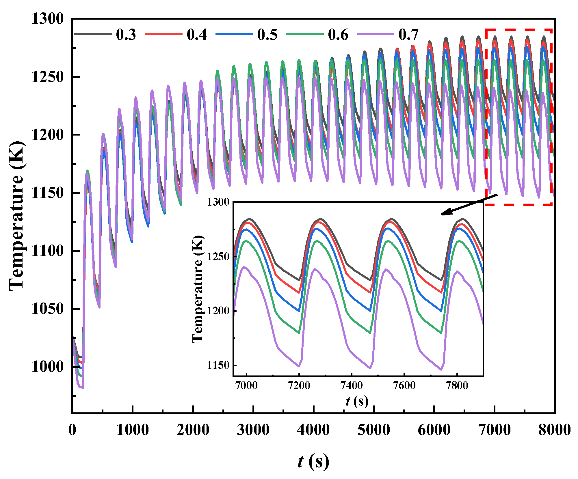
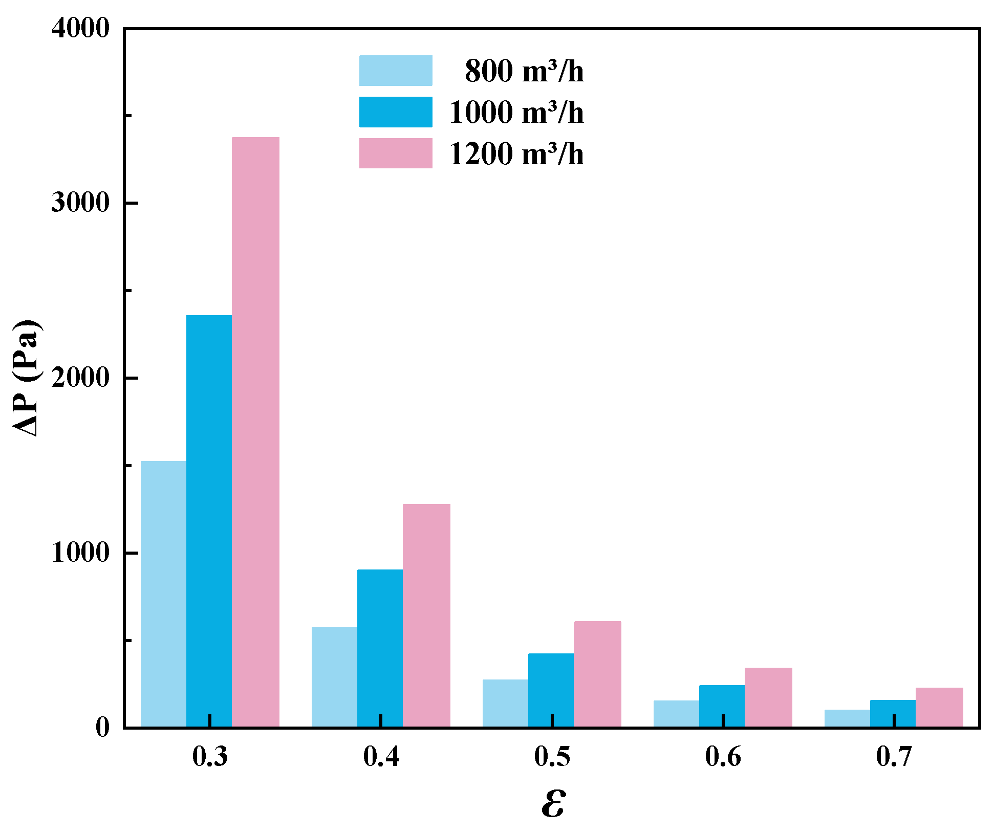
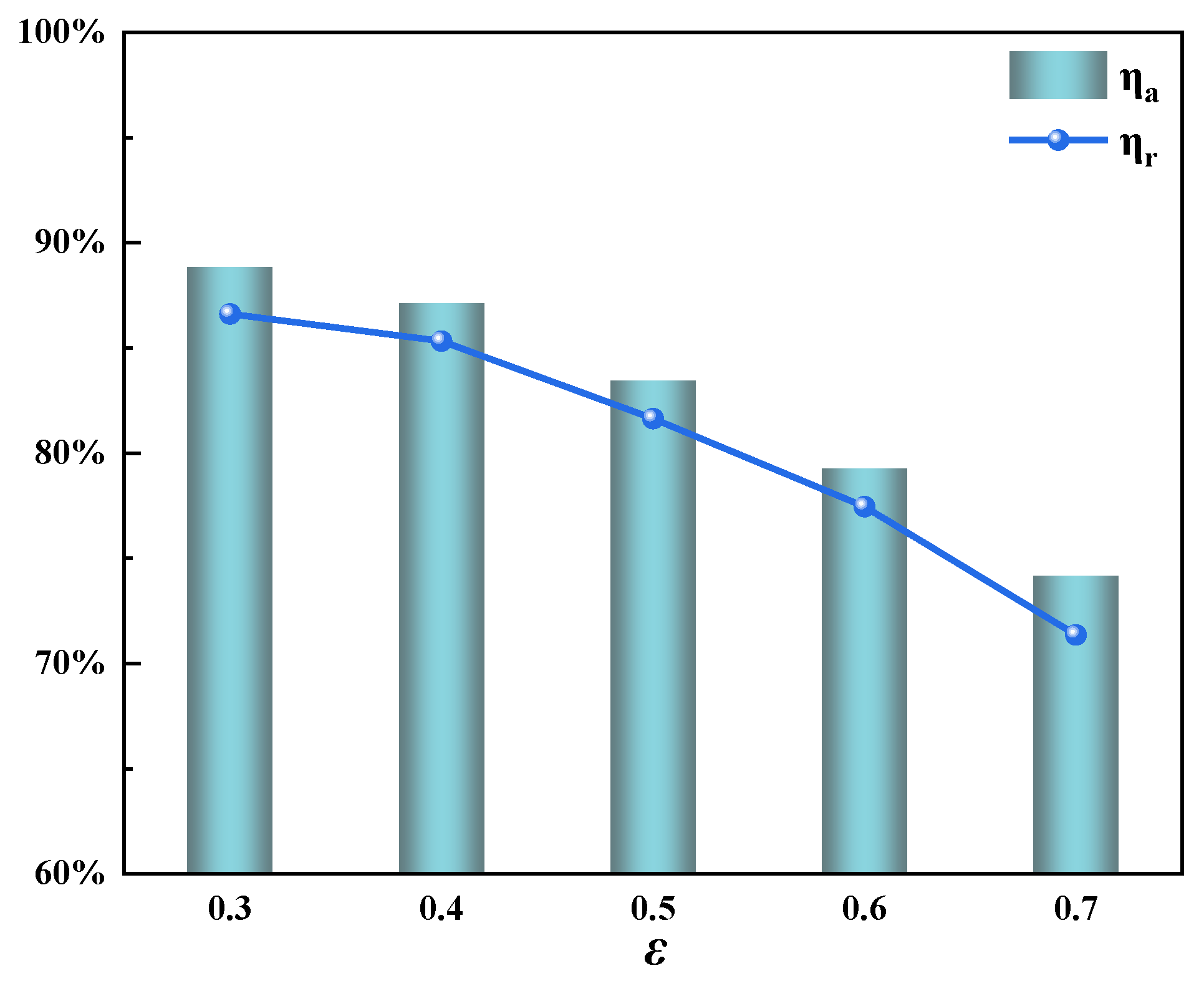
3.4. Effect of the Porosity in the Regenerator

In the preceding subsection, the optimal heat storage material was determined, for which porosity is extremely important for the gas flow and heat transfer. Thus, further studies were conducted to identify the most suitable porosity for maximizing the system performance. The reduction in porosity shrinks the space for gas circulation, increasing the gas flow resistance, as manifested by larger pressure losses below. In addition, as the cross-section of the flow channel shrinks, the gas flow velocity increases, and the strong flow disturbance inside the channel promotes convective heat transfer between the exhaust air and the heat storage material. The porosity of the honeycomb ceramics is dependent on their manufacturing process and methods. Through the porosity range given in [45], and based on the actual size of the experimental sample, five different porosity values were finally selected as the basis for calculation. Figure 14 shows the temperature response characteristics of the regenerator over time, with porosity set to five different values. As can be seen from this figure, the temperature curves at different porosities are the same. To be specific, they first increase and then periodically change with a certain value. For instance, when the porosity is 0.3, the regenerator temperature oscillates around 1250 K, with the smallest amplitude of 55.9 K. Increasing the porosity to 0.7 leads to the temperature oscillating around 1200 K while its amplitude is elevated to 90.2 K. Furthermore, it is worth noting that decreasing the porosity can elevate the regenerator temperature to some extent, which is beneficial to the system’s stability. This can be attributed to the fact that smaller porosity means a more solid medium per unit volume, which is accompanied by a higher thermal mass of the device. Such an increase can effectively improve the heat storage capacity of the heat storage body [35].
In theory, for a porous medium-assisted system, lower porosity can result in a larger pressure loss, which is not desirable in practical applications. Here, the pressure loss (ΔP) is the subtraction of the inlet pressure from the outlet pressure. Figure 15 illustrates the pressure loss variations in the system with the porosity and gas flow rate. It is clear that increasing the gas flow rate leads to a greater pressure loss, but the sensitivity becomes weak when the porosity is sufficiently high. Furthermore, for a specified gas flow rate, the pressure loss at ε = 0.3 is significantly higher than its counterparts, reaching up to 1500 Pa at the lowest gas flow rate (800 m3/h). By comparing the results of Figure 14 and Figure 15, it can be seen that when ε is decreased from 0.4 to 0.3, the pressure loss is increased by 2.6-fold, but the temperature is only elevated by 3 °C. This is because when the system is operating stably, the reaction heat can be effectively absorbed by the regenerator, and further enhancing the heat storage ability of the regenerator has a negligible effect with the same chemical energy input. Thus, the optimal porosity can be generally considered to be 0.4, in view of the relatively high regenerator temperature and low-pressure losses.
To provide a better understanding of the role played by porosity in the thermal characteristics of the system, the heat storage efficiency and heat release efficiency were also compared. Figure 16 shows the corresponding results at different porosities. It can be seen that both the heat storage efficiency and heat release efficiency present a monotonic change trend with the porosity. Low porosity is associated with high heat storage efficiency and heat release efficiency. This is quite understandable, as when a more solid matrix is inserted into the regenerator, the reaction heat can be transferred due to the relatively high thermal diffusivity. Varying the porosity from 0.3 to 0.7 results in the heat storage efficiency and heat release efficiency being decreased by 18.84% and 15.26%, respectively. This further explains the relationship of the temperature characteristics with the porosity, as depicted in Figure 14.
We further explored the economic feasibility or cost-effectiveness of implementing such systems. If the optimized thermal reversal combustor is successfully applied in industry, good economic gains will be achieved. For a VAM-fueled combustor operating with a gas flow rate of 1000 m3/h and a methane concentration of 0.7%, the cost arising from the heat storage material could be reduced by 14.3% through varying the fixed-bed structure. Meanwhile, from the perspective of energy saving and emission reduction, such a combustor is capable of consuming 1.2 t of methane per year, corresponding to a 22.4 t reduction in carbon dioxide emissions. Based on the carbon emission reduction price in the European market in 2024, a CMD gain of EUR 1700.7 could be obtained, signaling potential economic feasibility. Furthermore, it is worth noting that this economic analysis was conducted on a small-scale system. Certainly, the economic benefits would be enormous if such design schemes were applied to large-scale thermal reversal oxidation systems.

4. Conclusions

In the present work, the heat storage oxidation and stability performances of a VAM-fueled thermal reversal reactor with three fixed beds were numerically analyzed. The established computational model was first validated by comparing its predictions with experimental data. Then, it was applied to examine the effects of the combustion chamber/regenerator height ratio, heat storage material, and porosity on the combustion characteristics of the system. Key dimensionless parameters, including heat storage ratio and heat release ratio, were introduced to shed light on the phenomena observed. The main conclusions of this work are as follows:
(1)
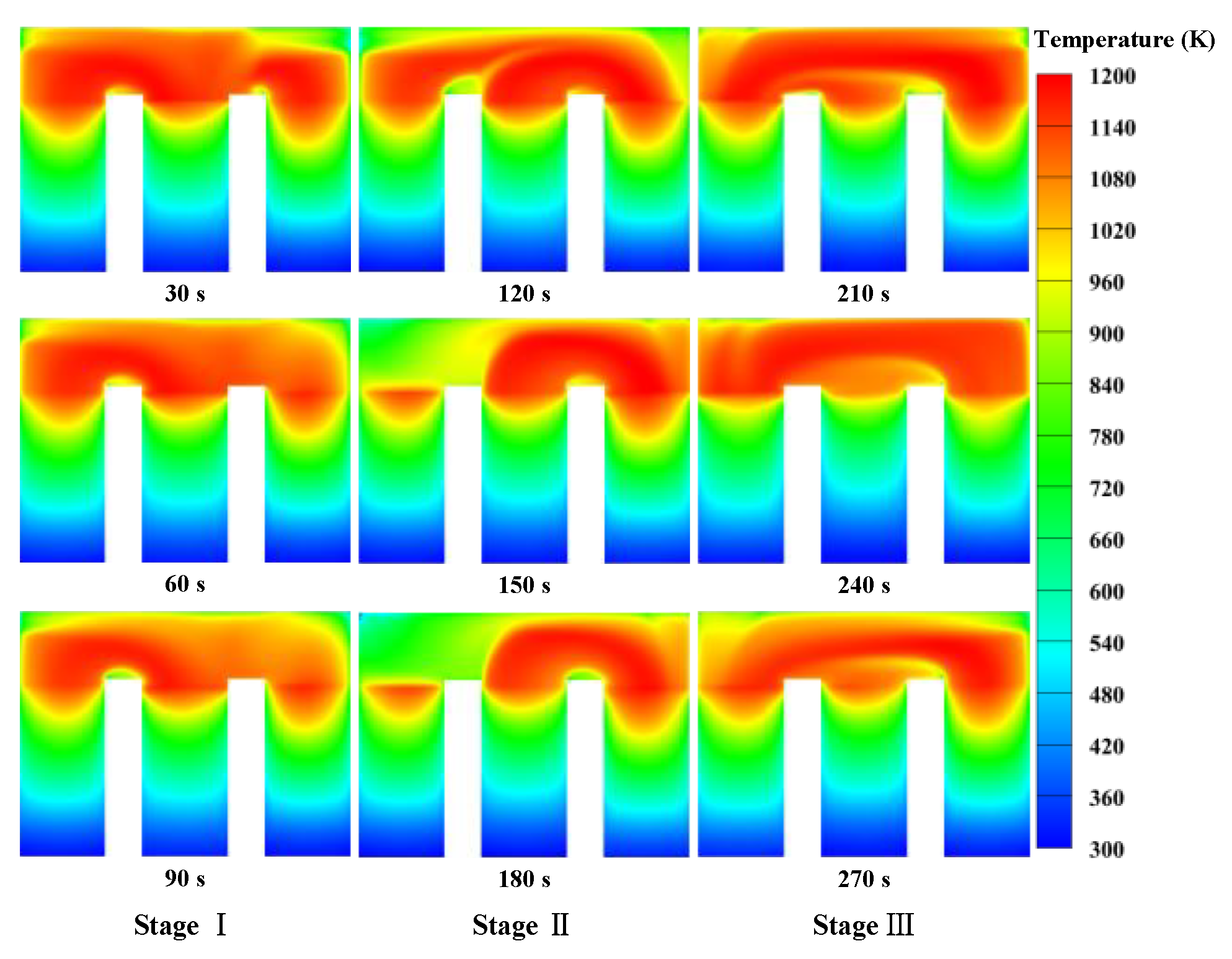
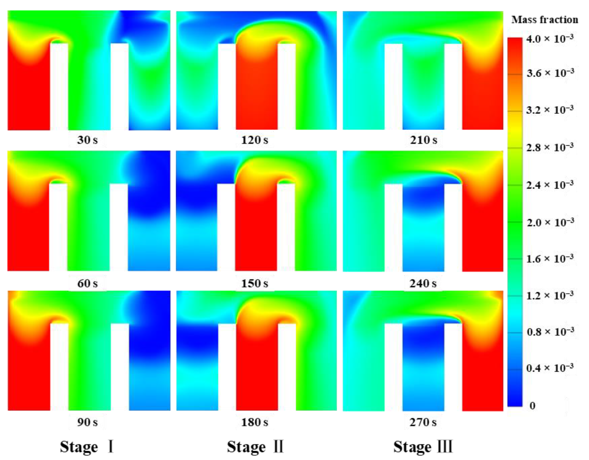
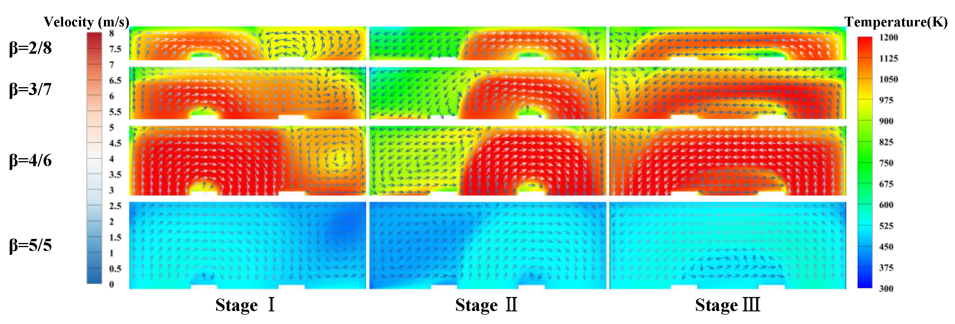
The combustion characteristics of each stage during a cycle exhibit significant differences. There could be a discontinuity in the temperature distribution when the gas is introduced from Regenerator 2 and swept from Regenerator 3 because of the different flow directions.
(2)
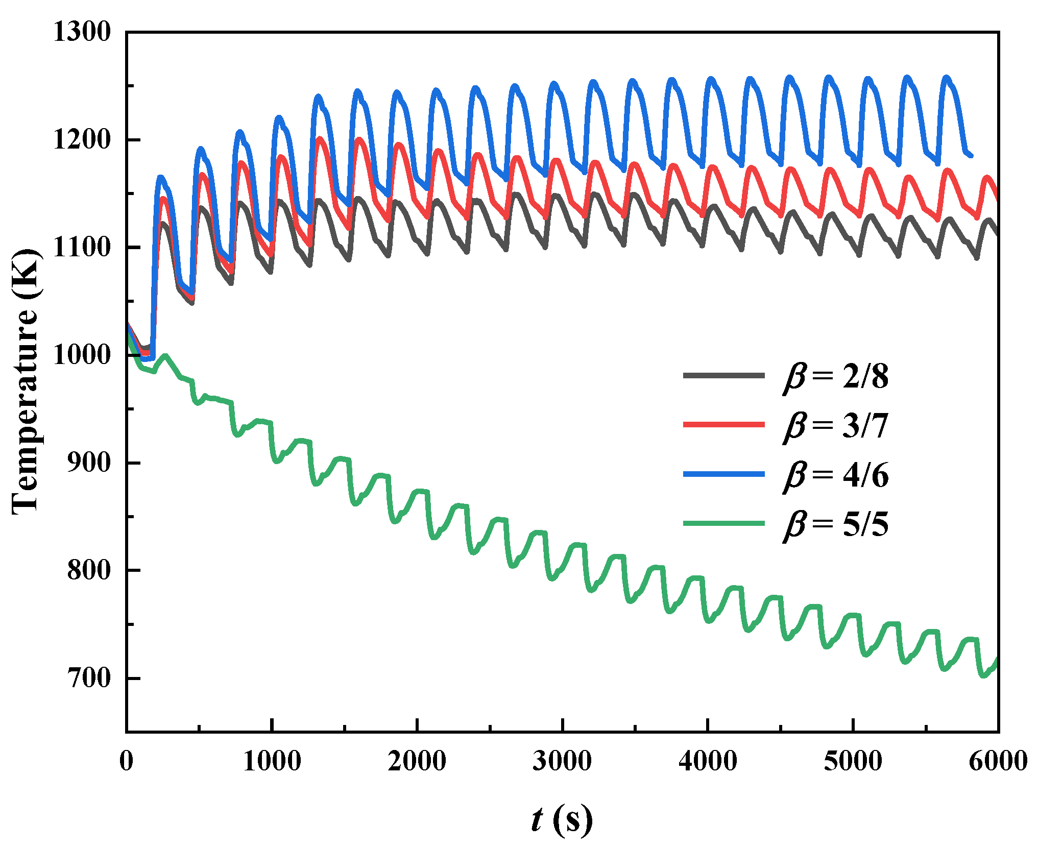
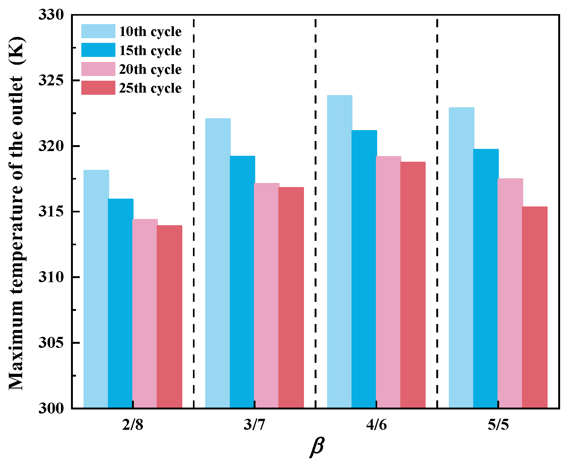
The regenerator temperature presents a non-monotonic change trend with the height ratio. The highest temperature tends to occur at the ratio of 4/6, due to the relatively high methane conversion rate, signifying a much stronger ability to resist system destabilization. However, below this value, the combustion system may become unstable.
(3)
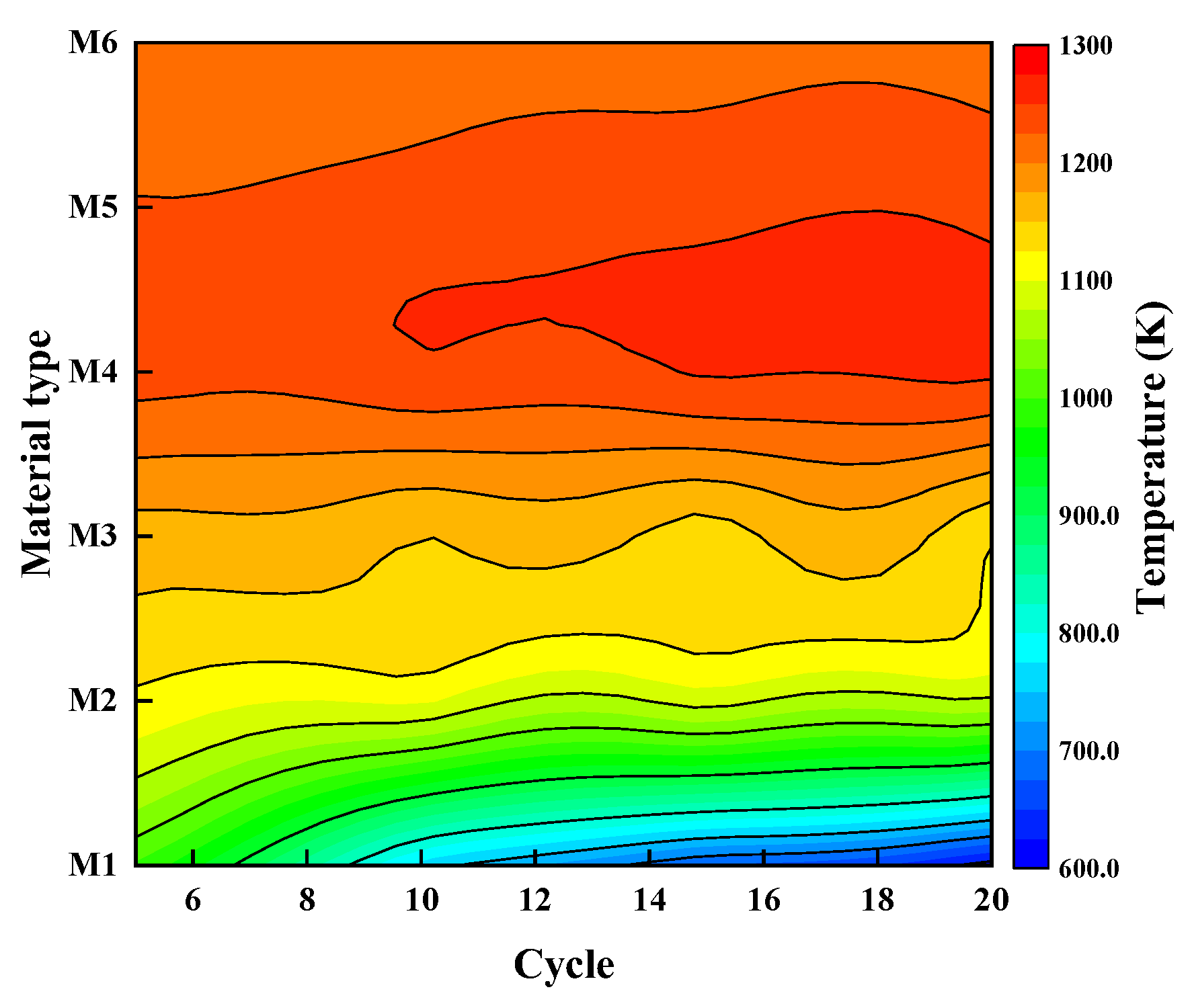
Among the heat storage materials investigated, the regenerator with mullite inserted is associated with the highest temperature regardless of the methane volume fraction. With the other materials, the temperature gradually decreases, and the system becomes unstable as SiC is adopted, indicating the importance of choosing a proper thermal diffusivity.
(4)
The porosity of the heat storage materials was shown to have little effect on the system’s stability. Decreasing the porosity can effectively reduce the oscillation amplitude of the regenerator temperature, but it also results in greater pressure losses.

Author Contributions

Z.Z.: funding acquisition, writing—original draft preparation; J.Y.: investigation, methodology, data curation; S.S.: funding acquisition, project administration, formal analysis; T.C.: formal analysis, writing—review and editing; A.T.: supervision, conceptualization, formal analysis, methodology; L.X.: resources, writing—review and editing. All authors have read and agreed to the published version of the manuscript.

Funding

This research was funded by the State Key Laboratory of Coal Mine Disaster Prevention and Control, grant number [2021SKLKF06], and by the National Natural Science Foundation of China, grant number [52174227]. The APC was funded by grant number [2021SKLKF06].

Data Availability Statement

The data supporting this present work are available from the corresponding author upon reasonable request.

Conflicts of Interest

The authors declare no conflicts of interest.

References

  1. Karakurt, I.; Aydin, G.; Aydiner, K. Mine ventilation air methane as a sustainable energy source. Renew. Sustain. Energy Rev. 2011, 15, 1042–1049. [Google Scholar] [CrossRef]
  2. Zhang, Z.; Wang, S.; Pan, M.; Lv, J.; Lu, K.; Ye, Y.; Tan, D. Utilization of hydrogen-diesel blends for the improvements of a dual-fuel engine based on the improved Taguchi methodology. Energy 2024, 292, 130474. [Google Scholar] [CrossRef]
  3. Tan, D.; Dong, R.; Zhang, Z.; Zhang, B.; Jiang, F.; Ye, Y.; Li, D.; Liu, H. Multi-objective impact mechanism on the performance characteristic for a diesel particulate filter by RF-NSGA III-TOPSIS during soot loading. Energy 2024, 286, 129582. [Google Scholar] [CrossRef]
  4. Zhou, Y.; Liu, Y.; Shi, Y.; Zhang, Y.; Shi, J.; Sun, P. Strategies for heat recovery in a reverse flow reactor designed to lessen coal mine methane emissions test. Energy Sources Part A Recovery Util. Environ. Eff. 2023, 45, 8665–8685. [Google Scholar] [CrossRef]
  5. Zhang, Y.; Doroodchi, E.; Moghtaderi, B. Utilization of ventilation air methane as an oxidizing agent in chemical looping combustion. Energy Convers. Manag. 2014, 85, 839–847. [Google Scholar] [CrossRef]
  6. Cai, T.; Zhao, D.; Gutmark, E. Overview of fundamental kinetic mechanisms and emission mitigation in ammonia combustion. Chem. Eng. J. 2023, 458, 141391. [Google Scholar] [CrossRef]
  7. Ostrowski, P.; Pronobis, M.; Remiorz, L. Mine emissions reduction installations. Appl. Therm. Eng. 2015, 84, 390–398. [Google Scholar] [CrossRef]
  8. Su, S.; Beath, A.; Guo, H.; Mallett, C. An assessment of mine methane mitigation and utilisation technologies. Prog. Energy Combust. Sci. 2005, 31, 123–170. [Google Scholar] [CrossRef]
  9. You, C.; Xu, X. Utilization of ventilation air methane as a supplementary fuel at a circulating fluidized bed combustion boiler. Environ. Sci. Technol. 2008, 42, 2590–2593. [Google Scholar] [CrossRef] [PubMed]
  10. Lan, B.; Li, Y.-R. Numerical simulation of thermodynamic performance in a honeycomb ceramic channel. In Proceedings of the 3rd International Symposium on Mine Safety Science and Engineering, Montreal, QC, Canada, 13–19 August 2016; pp. 219–224. [Google Scholar]
  11. Marín, P.; Ho, W.; Ordóñez, S.; Díez, F.V. Demonstration of a control system for combustion of lean hydrocarbon emissions in a reverse flow reactor. Chem. Eng. Sci. 2010, 65, 54–59. [Google Scholar] [CrossRef]
  12. Li, Z.; Wu, Z.; Qin, Z.; Zhu, H.; Wu, J.; Wang, R.; Lei, L.; Chen, J.; Dong, M.; Fan, W. Demonstration of mitigation and utilization of ventilation air methane in a pilot scale catalytic reverse flow reactor. Fuel Process. Technol. 2017, 160, 102–108. [Google Scholar] [CrossRef]
  13. Zhou, F.; Xia, T.; Wang, X.; Zhang, Y.; Sun, Y.; Liu, J. Recent developments in coal mine methane extraction and utilization in China: A review. J. Nat. Gas Sci. Eng. 2016, 31, 437–458. [Google Scholar] [CrossRef]
  14. Li, Z.; Qin, Z.; Zhang, Y.; Wu, Z.; Wang, H.; Li, S.; Dong, M.; Fan, W.; Wang, J. A logic-based controller for the mitigation of ventilation air methane in a catalytic flow reversal reactor. Front. Chem. Sci. Eng. 2013, 7, 347–356. [Google Scholar] [CrossRef]
  15. Su, S.; Yu, X. A 25 kWe low concentration methane catalytic combustion gas turbine prototype unit. Energy 2015, 79, 428–438. [Google Scholar] [CrossRef]
  16. Gosiewski, K.; Pawlaczyk, A. Catalytic or thermal reversed flow combustion of coal mine ventilation air methane: What is better choice and when? Chem. Eng. J. 2014, 238, 78–85. [Google Scholar] [CrossRef]
  17. Gosiewski, K.; Matros, Y.S.; Warmuzinski, K.; Jaschik, M.; Tanczyk, M. Homogeneous vs. catalytic combustion of lean methane—Air mixtures in reverse-flow reactors. Chem. Eng. Sci. 2008, 63, 5010–5019. [Google Scholar] [CrossRef]
  18. Gao, Z.; Liu, Y.; Gao, Z. Heat extraction characteristic of embedded heat exchanger in honeycomb ceramic packed bed. Int. Commun. Heat Mass Transf. 2012, 39, 1526–1534. [Google Scholar] [CrossRef]
  19. Gao, Z.; Liu, Y.; Gao, Z. Influence of packed honeycomb ceramic on heat extraction rate of packed bed embedded heat exchanger and heat transfer modes in heat transfer process. Int. Commun. Heat Mass Transf. 2015, 65, 76–81. [Google Scholar] [CrossRef]
  20. Wang, Y.; Liu, Y.; Cao, Q.; Wang, C.A.; Che, D. Homogeneous combustion of fuel ultra-lean methane–air mixtures: Experimental study and simplified reaction mechanism. Energy Fuels 2011, 25, 3437–3445. [Google Scholar] [CrossRef]
  21. Shahamiri, S.; Wierzba, I. Modeling catalytic oxidation of lean mixtures of methane–air in a packed-bed reactor. Chem. Eng. J. 2009, 149, 102–109. [Google Scholar] [CrossRef]
  22. Chaouki, J.; Guy, C.; Sapundzhiev, C.; Kusohorsky, D.; Klvana, D. Combustion of methane in a cyclic catalytic reactor. Ind. Eng. Chem. Res. 1994, 33, 2957–2963. [Google Scholar] [CrossRef]
  23. Marín, P.; Díez, F.V.; Ordóñez, S. Reverse flow reactors as sustainable devices for performing exothermic reactions: Applications and engineering aspects. Chem. Eng. Process. Process Intensif. 2019, 135, 175–189. [Google Scholar] [CrossRef]
  24. Qi, X.; Liu, Y.; Xu, H.; Liu, Z.; Liu, R. Modeling thermal oxidation of coal mine methane in a non-catalytic reverse-flow reactor. J. Mech. Eng. Stroj. Vestn. 2014, 60, 495–505. [Google Scholar] [CrossRef]
  25. Zhou, Y.; Shi, Y.; Liu, Y.; Sun, P.; Mao, M. Experimental and simulation research on heat extraction characteristics from a pilot-scale reverse flow reactor for low-grade energy. Appl. Therm. Eng. 2023, 220, 119761. [Google Scholar] [CrossRef]
  26. Gosiewski, K.; Pawlaczyk, A.; Jaschik, M. Energy recovery from ventilation air methane via reverse-flow reactors. Energy 2015, 92, 13–23. [Google Scholar] [CrossRef]
  27. Banerjee, A.; Saveliev, A.V. High temperature heat extraction from counterflow porous burner. Int. J. Heat Mass Transf. 2018, 127, 436–443. [Google Scholar] [CrossRef]
  28. Lan, B.; Li, Y.-R. Numerical study on thermal oxidation of lean coal mine methane in a thermal flow-reversal reactor. Chem. Eng. J. 2018, 351, 922–929. [Google Scholar] [CrossRef]
  29. Deng, H.X.; Wen, Y.X.; Xiao, Q.; Xiao, Y.H. Parametric study of thermal flow-reversal reactor for ventilation air methane oxidation. Appl. Mech. Mater. 2013, 372, 406–409. [Google Scholar] [CrossRef]
  30. Chen, G.; Chi, Y.; Yan, J.-H.; Ni, M.-J. Effect of periodic variation of the inlet concentration on the performance of reverse flow reactors. Ind. Eng. Chem. Res. 2011, 50, 5448–5458. [Google Scholar] [CrossRef]
  31. Mao, M.; Liu, Y.; Shi, J.; Li, C.; Zhang, Q. Experimental study on control of flame inclination in a thermal flow reversal reactor with extra lean premixed methane/air intake. Fuel 2022, 318, 123722. [Google Scholar] [CrossRef]
  32. Mao, M.; Shi, J.; Liu, Y.; Gao, M.; Chen, Q. Experimental investigation on control of temperature asymmetry and nonuniformity in a pilot scale thermal flow reversal reactor. Appl. Therm. Eng. 2020, 175, 115375. [Google Scholar] [CrossRef]
  33. Marín, P.; Ordóñez, S.; Díez, F.V. Monoliths as suitable catalysts for reverse-flow combustors: Modeling and experimental validation. AIChE J. 2010, 56, 3162–3173. [Google Scholar] [CrossRef]
  34. Shi, Y.; Liu, Y.; Zhou, Y.; Sun, P.; Mao, M.; Zhang, Y. Study on dynamic heat extraction characteristics of heat exchanger tube embedded in thermal flow reverse reactor for heat recovery. Process Saf. Environ. Prot. 2022, 162, 846–858. [Google Scholar] [CrossRef]
  35. Litto, R.; Hayes, R.; Sapoundjiev, H.; Fuxman, A.; Forbes, F.; Liu, B.; Bertrand, F. Optimization of a flow reversal reactor for the catalytic combustion of lean methane mixtures. Catal. Today 2006, 117, 536–542. [Google Scholar] [CrossRef]
  36. Wang, Y.; Dong, M.; Li, H.; Liu, Y.; Shang, Q. Study on thermal stress of honeycomb ceramic regenerators with different parameters. Strength Mater. 2014, 46, 256–261. [Google Scholar] [CrossRef]
  37. Rao, K.; Liu, Y.; An, T.; Shen, Y. Numerical analysis of oxidation performance of basalt fiber bundle thermal flow-reversal reactor. Appl. Therm. Eng. 2022, 215, 118886. [Google Scholar]
  38. Zazhigalov, S.; Elyshev, A.; Zagoruiko, A. Catalytic reverse-flow oxidation process in reactors of various designs: Axial, side and tangential gas inlet. Chem. Eng. Res. Des. 2023, 191, 364–374. [Google Scholar] [CrossRef]
  39. Kushwaha, A.; Poirier, M.; Hayes, R.; Sapoundjiev, H. Heat extraction from a flow reversal reactor in lean methane combustion. Chem. Eng. Res. Des. 2005, 83, 205–213. [Google Scholar] [CrossRef]
  40. Mei, H.; Li, C.; Liu, H.; Ji, S. Simulation of catalytic combustion of methane in a monolith honeycomb reactor. Chin. J. Chem. Eng. 2006, 14, 56–64. [Google Scholar] [CrossRef]
  41. Cai, T.; Tang, A.; Li, C. Experimental and kinetic analyses on the flame dynamics and stabilization of ammonia/hydrogen-air mixtures in a micro-planar combustor. Chem. Eng. J. 2023, 477, 147038. [Google Scholar] [CrossRef]
  42. Zhang, Q.; Tang, A.; Cai, T.; Huang, Q. Analysis of entropy generation and exergy efficiency of the methane/dimethyl ether/air premixed combustion in a micro-channel. Int. J. Heat Mass Transf. 2024, 218, 124801. [Google Scholar] [CrossRef]
  43. Pu, G.; Li, X.; Yuan, F. Numerical study on heat transfer efficiency of regenerative thermal oxidizers with three canisters. Processes 2021, 9, 1621. [Google Scholar] [CrossRef]
  44. Zou, W.F.; Lan, B. The numerical simulation research on thermal flow-reversal reactor of mine ventilation gas. Adv. Mater. Res. 2014, 926, 1627–1631. [Google Scholar] [CrossRef]
  45. Colombo, P.; Degischer, H. Highly porous metals and ceramics. Mater. Sci. Technol. 2010, 26, 1145–1158. [Google Scholar] [CrossRef]
Figure 1. Schematic of the simulated reactor: (a) physical geometry; (b) specific dimensions.
Processes 12 01193 g001
Figure 2. Comparison of the regenerator temperature at different mesh resolutions.
Processes 12 01193 g002
Figure 3. The schematic diagram of the test platform for VAM heat storage and oxidation.
Processes 12 01193 g003
Figure 4. Comparison of experimental and numerical temperature profiles at different methane volume fractions.
Processes 12 01193 g004
Figure 5. Temporal temperature distributions of the reactor over a cycle.
Processes 12 01193 g005
Figure 6. Temporal variations in combustion chamber temperatures under typical destabilization conditions.
Processes 12 01193 g006
Figure 7. Profiles of the temperature with time under different chamber/regenerator height ratios.
Processes 12 01193 g007
Figure 8. Variations in the maximum outlet temperature with β at the end of four different cycles.
Processes 12 01193 g008
Figure 9. Temperature contours overlapped with velocity vectors at different height ratios.
Processes 12 01193 g009
Figure 10. Comparison of methane conversion rates at various height ratios and gas flow rates.
Processes 12 01193 g010
Figure 11. Comparison of the heat storage ratio and heat release ratio from the regenerator with β: (a) Qin = 800 m3/h; (b) Qin = 1000 m3/h; (c) Qin = 1200 m3/h.
Processes 12 01193 g011
Figure 12. Temperature evolutions of the regenerator over time with various heat storage materials: (a) Cin = 0.7%; (b) Cin = 0.8%.
Processes 12 01193 g012
Figure 13. Average temperatures of the combustion chamber over 20 cycles for different heat storage materials at Cin = 0.7%.
Processes 12 01193 g013
Figure 14. Temporal evolution of the regenerator temperature when the porosity is set to 5 different values.
Processes 12 01193 g014
Figure 15. A comparison of the pressure loss at various porosities and gas flow rates.
Processes 12 01193 g015
Figure 16. Variations in the heat storage and heat release efficiencies with different porosities.
Processes 12 01193 g016
Table 1. The working principle of the heat storage and oxidation system during a cycle.
No.Regenerator 1Regenerator 2Regenerator 3
Stage IInlet 1 (VAM)Outlet 2Inlet 3 (Air)
Stage IIInlet 1 (Air)Inlet 2 (VAM)Outlet 3
Stage IIIOutlet 1Inlet 2 (Air)Inlet 3 (VAM)
Table 2. Mechanism and kinetic parameters of two-step methane–air reaction.
No.Reaction StepsAr (1/s)Er (J/mol)
12CH4 + 3O2 → 2CO + 4H2O5.012 × 10110
22CO + O2 → 2CO22.239 × 10120
32CO2 → 2CO + O25 × 1080
Table 3. Thermophysical properties of the heat storage materials considered.
No.Material NameDensity (kg/m3)Heat Capacity (J/(g·K))Thermal Conductivity (W/(m·K))Thermal Diffusivity (mm2/s)
M1SiC [18]316011958723
M2Steel [18]78541169303.3
M3Si4N3 [18]240011558.83.2
M4Mullite [44]2700100031.1
M5Cordierite [37]230098120.9
M6Basalt [45]28708981.60.6
Disclaimer/Publisher’s Note: The statements, opinions and data contained in all publications are solely those of the individual author(s) and contributor(s) and not of MDPI and/or the editor(s). MDPI and/or the editor(s) disclaim responsibility for any injury to people or property resulting from any ideas, methods, instructions or products referred to in the content.

