Article

Thermal Transportation in Heat Generating and Chemically Reacting MHD Maxwell Hybrid Nanofluid Flow Past Inclined Stretching Porous Sheet in Porous Medium with Solar Radiation Effects

by
Mdi Begum Jeelani
1,*,
Amir Abbas
2,* and
Nouf Abdulrahman Alqahtani
1
1
Department of Mathematics and Statistics, College of Science, Imam Mohammad Ibn Saud Islamic University (IMSIU), Riyadh 13314, Saudi Arabia
2
Department of Mathematics, Faculty of Science, University of Gujrat, Sub-Campus, Mandi Bahauddin 50400, Pakistan
*
Authors to whom correspondence should be addressed.
Processes 2024, 12(6), 1196; https://doi.org/10.3390/pr12061196
Submission received: 5 May 2024 / Revised: 2 June 2024 / Accepted: 4 June 2024 / Published: 11 June 2024
(This article belongs to the Special Issue Heat and Mass Transfer in Energy Engineering)

Abstract

:
The emerging concept of hybrid nanofluids has grabbed the attention of researchers and scientists due to improved thermal performance because of their remarkable thermal conductivities. These fluids have enormous applications in engineering and industrial sectors. Therefore, the present research study examines thermal and mass transportation in hybrid nanofluid past an inclined linearly stretching sheet using the Maxwell fluid model. In the current problem, the hybrid nanofluid is engineered by suspending a mixture of aluminum oxide A l 2 O 3   and copper C u nanoparticles in ethylene glycol. The fluid flow is generated due to the linear stretching of the sheet and the sheet is kept inclined at the angle ζ = π / 6 embedded in porous medium. The current proposed model also includes the Lorentz force, solar radiation, heat generation, linear chemical reactions, and permeability of the plate effects. Here, in the current simulation, the cylindrical shape of the nanoparticles is considered, as this shape has proven to be excellent for the thermal performance of the nanomaterials. The governing equations transformed into ordinary differential equations are solved using MATLAB bvp4c solver. The velocity field declines with increasing magnetic field parameter, Maxwell fluid parameter, volume fractions of nanoparticles, and porosity parameter but increases with growing suction parameter. The temperature drops with increasing magnetic field force and suction parameter values but increases with increasing radiation parameter and volume fraction values. The concentration profile increases with increasing magnetic field parameters, porosity parameters, and volume fractions but reduces with increasing chemical reaction parameters and suction parameters. It has been noted that the purpose of the inclusion of thermal radiation is to augment the temperature that is serving the purpose in the current work. The addition of Lorentz force slows down the speed of the fluid and raises the boundary layer thickness, which is visible in the current study. It has been concluded that, when heat generation parameters increase, the temperature field increases correspondingly for both nanofluids and hybrid nanofluids. The increase in the volume fraction of the nanoparticles is used to enhance the thermal performance of the hybrid nanofluid, which is evident in the current results. The current results are validated by comparing them with published ones.

1. Introduction

Fluids are usually used as heat transfer carriers in heat transfer equipment. These fluids, as carriers of heat transfer, are utilized in hydronic heating and cooling systems in buildings, cooling systems in the transportation industry, industrial process heating, cooling systems in the petrochemical and textile industries, etc. In these significant applications of these fluids, what matters more is their thermal conductivity and, hence, it plays an important role. Conventional fluids, such as water, ethylene glycol, oil, etc., have low thermal conductance; therefore, their thermal efficiency is not up to the mark. This issue diverted the attention of scientists and researchers toward new types of fluids that have large thermal conductivity compared to conventional fluids. It was found that fluids containing suspended nanoparticles have higher thermal conductivity than usual fluids, and this new class of fluids is known as nanofluid. In 1993, Choi and Eastman [1] were the first to suggest a new class of fluids called nanofluid, a fluid with suspended nanoparticles in conventional heat transfer fluids (base fluids). Further, they conveyed that nanofluids have greater thermal properties than base fluids in which the nanoparticles are suspended. The preparation of nanofluids is conducted by mixing nanoparticles with usual base fluids like water, oil, and ethylene glycol. In the literature, two major methods are adopted to prepare the nanofluids: the one-step technique and the two-step technique. In the one-step method, the nanofluids are prepared via the direct deposition of the nanoparticles using the physical vapor deposition and liquid chemical methods (direct condensation of nano-powders from the vapor phase into fluid flow with low vapor pressure). This method was first developed by Akoh et al. [2] and is known as the Vacuum Evaporation onto a Running Oil Substrate (VEROS) technique. In the two-step method, in the first stage, the nanoparticles are prepared like a dry powder. Then, in the second stage, these nanoparticles are mixed in base fluids. This method is a very suitable technique for high mass production. Eastman et al. [3] and Lee et al. [4] have used the two-step method to harvest A l 2 O 3 nanofluids. They used oxide nanoparticles to produce nanofluids. The two-step method for the preparation of nanofluids using oxide nanoparticles works very well compared to the use of metallic nanoparticles. Eastman et al. [5] studied the nanofluid flow using ethylene glycol as a base fluid and nanoparticles of copper material mixed in it. They concluded that copper nanoparticles in ethylene glycol has more thermal efficiency than pure ethylene glycol or ethylene glycol containing the same volume fraction of dispersed oxide nanoparticles.
For the simulation of the nanofluids’ fluid flow problems, two types of model approach are used: the two-phase model approach and the single-phase model approach. In the two-phase model approach, the fluids and nanoparticles are not in thermal equilibrium and two main factors, Brownian motion and thermophoresis, are responsible for heat transfer. In the two-phase model, slip velocities between the nanoparticles and base-fluid molecules may not be zero due to several factors viz. gravity, Brownian forces, and friction between the solid particles and fluid molecules. Buongiorno and Hu [6] investigated how nanofluids can be used in advanced nuclear power plants using a special type of nanoparticles made from different conducting materials. Buongiorno [7] developed the theoretical model for the simulation of nanofluids based on the two-phase model approach. He considered seven slip mechanisms that can generate relative velocity between nanoparticles and the base fluids. These seven slip mechanisms include inertia, Brownian diffusion, thermophoresis, diffusiophoresis, Magnus effect, fluid drainage, and gravity. In his study, he concluded that only two mechanisms, Brownian diffusion and thermophoresis, are significant slip mechanisms in nanofluids. Based on his findings, he developed a non-homogenous equilibrium model for nanofluid flow problem simulation that contains mass, momentum, energy, and concentration equations. In the single-phase model method, the nanofluids are considered pure fluids and only the mass, momentum, and energy equations are considered. In this approach, fluid and nanoparticles are in the same thermal equilibrium. From the experimental record, the thermal and viscosity correlations can be taken. The concentration of nanoparticles is considered the same in this model. Much research has been carried out on nanofluid flow problems using the single-phase model. To enhance the thermal performance of the devices used in industry and engineering, the researchers are placing the focus on applications of nanofluids. Tiwari and Das [8] studied the single-phase model problem for nanofluids to display heat transfer enhancement in a two-sided lid-driven cavity heated and filled with nanofluids. This thrust led the researchers to introduce a new class of fluids prepared by combining two different types of nanoparticles in a base fluid. This is an extension of the mono-nanofluids. When a combination of two kinds nanoparticles is dispersed in a base fluid like water, ethylene, or other liquids, this new class of fluids is called hybrid nanofluids.
Hybrids are advanced nanofluids prepared by mixing two different nanoparticles (NPs) in a base fluid. It has been investigated that the thermal conductance of the hybrid nanofluids is greater than that of simple nanofluid and, hence, the thermal performance of these fluids is exemplary. Therefore, the research community has made their topic of investigation the problems, including hybrid nanofluid models. In comparison to base fluids and nanofluids, hybrid nanofluids will have superior thermal properties [9]. These fluids are preferable to regular fluids in that they are [10]. Probably for the first time, Turcu et al. [11] prepared hybrid nanofluids using polypyrrole–carbon nanotubes (CNTs) and multiwall carbon nanotubes (MWCNTs) on magnetic Fe3O4 hybrid nanoparticles. Jha and Ramaprabhu [12] examined the suspension of metallic nanoparticles dispersed on multiwalled carbon nanotubes (MWNTs) outer surface in ethylene and water as base fluid. Suresh et al. [13] proposed the investigation of the hybrid nanofluids that were synthesized using oxide and copper nanoparticles in water by taking different volume fractions of the nanoparticles. They concluded that there is an augmentation in both thermal conductivity and viscosity of the fluids when the volume concentration of nanoparticles is increased. In [13,14], authors reviewed comprehensively the significant applications of hybrid nanofluids in nanotechnology, cooling systems, electronic cooling, and energy storage systems.
In hybrid nanofluid, both Newtonian and non-Newtonian flow models are used in recent studies. It has been concluded that the dispersion of nanoparticles is very effective in non-Newtonian fluids to enhance the thermal enhancement of the fluids. Therefore, the research community paid their attention towards such flow models using nanoparticles in base fluids, as the suspension of nanoparticles in base fluids predicts the non-Newtonian behavior in viscosity. Jeelani and Abbas [15] disclosed the study of hybrid nanofluid prepared by mixing copper and oxide nanoparticles in ethylene glycol, and the Maxwell fluid model was considered for flow over a permeable stretching inclined sheet incorporating porous medium impact. They determined the solution of the flow equation using the BVP4C solver, which is based on the collocation technique. By integrating solar radiation, plate suction, medium porosity, inclination angle, and the impacts of cylindrical-shaped nanoparticles using hybrid nanofluids in Maxwell fluid, they expand the model (see [15]) and present it in [16]. Abbas et al. [17] carried out the study of hybrid nanofluids, counting methanol as a base fluid in which alloy particles are suspended using the Williamson fluid model. They encountered irregular heat sources and sinks and magnetic field effects in the flow generated due to the thin moving needle. Abbas et al. [18] extended the work given in [17], incorporating the porosity of the medium effects combined with suction, Lorentz force, and an irregular heat source and sink in the flow of Williamson fluid on a thin needle moving at constant speed. The process of heat and mass transmission in a hybrid nanofluid coupled with the Maxwell fluid model was studied by Rauf et al. [19]. They controlled the flow produced by a linearly stretched sheet by means of the Lorentz force, thermal radiation, and the Soret and Dufour phenomena. Kumar and Reddy [20] examined the behavior of a first-order homogeneous chemical reaction through a stretching surface with heat generation and absorption effects and the non-Newtonian Maxwell nanofluid flow.
In the above studies, works on nanofluids and hybrid nanofluid using Newtonian and non-Newtonian fluid flow models have been highlighted using several geometries. Now, we turn our attention toward the physical significance of the stretching and moving surfaces taken in vertical, horizontal, and inclined directions to generate the flow of hybrid nanofluids coupled with Newtonian and non-Newtonian fluid flow models. The applications of the stretching sheets have been observed in many phenomena, like material processing, polymer processing, aerospace engineering, paper production, food processing, civil engineering, mechanical engineering, nanotechnology, etc. Due to the above-mentioned uses of the stretching sheets, a lot of work on such geometries in fluid flow problems has been published. Blasius [21] solved the classical problem of the fluid flow past a stationary and horizontal plate that is placed in the moving fluid stream for the first time. There is another problem of fluid mechanics in which a plate moves with constant velocity in stationary fluid, and this problem was handled by Sakiadis [22]. Afterwards, many solutions have been obtained for different aspects, such as the boundary layer flow problem. Cortell [23] inspected the heat and fluid flow mechanism with thermal radiation influence over a flat plate moving at constant velocity. Khan and Pop [24] first examined the boundary layer flow of nanofluid on a stretching surface. They took the two-phase fluid flow model of nanofluid in which Brownian diffusion and thermophoresis mechanisms were encountered. The inclined sheet problem has numerous applications, like the understanding and stress distribution of inclined roofs, walls, and inclined aircraft wings; the modeling and structure of bridge inclined decks and supporting structures; the deformation of inclined pipelines; and the modeling of conveyer belts. Abbas et al. [25] explored the fluid and heat transfer processes over the inclined moving sheet under the impact of thermal radiation and variable density. It was concluded that heat and boundary layer thickness greatly depend on radiation and variable density parametric effects. Alabdulhadi et al. [26] addressed the thermal transportation of a hybrid nanofluid prepared by using silver–magnesium oxide suspended in water past the inclined stretching and shrinking sheet. They determined the dual solution to the problem. Anuar et al. [27] proposed the research work on the hybrid nanofluid flow past a shrinking and stretching sheet kept in an inclined manner by incorporating buoyancy and suction effects. Khan et al. [28] addressed the study focusing on the convection heat transfer in hybrid nanofluid along a moving inclined flat surface in the inclusion of thermophoretic transportation and solar radiation under transpiration impact.
Researchers’ interest in the study of fluid flow and thermal energy transmission in porous media has grown significantly. A material or substance that permits fluid to pass through is called a porous medium. These pores facilitate the passage of gases or liquids through the medium. In addition, scientists develop simulations and computational modeling techniques to explain fluid flow stretching inclined sheets in porous media. Numerous industries, including the oil and gas sector, energy storage, and conversion, can benefit from its relevance. Keeping in mind the above-mentioned applications, the research fellows put their efforts toward the flow problems of Newtonian and non-Newtonian fluids in nanofluids and hybrid nanofluids. The analysis of hybrid nanofluids based on the suspension of oxide and copper nanoparticles in water for Newtonian fluid, taking both assisting and opposing flows in the porous medium, was carried out by Waini et al. [29]. Eid et al. [30] presented a numerical study of the effects of Lorentz force, thermal conductivity variation, heat generation, and slip conditions on the hybrid nanofluid flow past an exponentially stretching sheet in a porous medium. Algehyne et al. [31] carried out investigations on the thermal efficiency of Maxwell hybrid nanofluid past a porous sheet and solved the flow equations using the finite element method. Gul et al. [32] explored the study of the thin-film flow of Maxwell hybrid nanofluid past an inclined plane fixed in a porous space. The numerical study on the mechanism of hybrid nanofluid flow under the impact of magnetic field and entropy generation in porous medium was documented by Mebarek-Oudina et al. [33]. Sagheer et al. [34] presented the numerical solutions of Maxwell hybrid nanofluid past a non-linear stretching sheet, and they found a non-similar solution to the proposed problem. Rashad et al. [35] conducted analysis on the study of Maxwell hybrid nanofluid flow in porous space. Effects of variable thermal conductivity, Lorentz force, heat source, and sink past the stretching sheet have been accomplished. It has been discovered that increasing the permeability, Maxwell parameter, and magnetic field of porous media reduces heat and mass transport. Moreover, mass transfer increases when the order of chemical events rises. Mass transfer is increased while heat transfer is decreased when thermal conductivity and the heat source or sink are increased. Devi et al. [36] investigated the fluid flow and heat transfer in hybrid nanofluid flow along a sheet, taking into account the suction effects. Safdar et al. [37] carried out a numerical study on magnetohydrodynamic Maxwell nanofluid flow over porous stretching sheets under the impact of gyrotactic microorganisms. They assumed the thermal radiation and buoyancy force effects in their study. Ahmed et al. [38] observed the controlling impact of magnetohydrodynamics on Maxwell nanofluid transient flow. They counted solar rays in a nonlinear manner under convective boundary conditions. Mukhtar et al. [39] explored the magnetohydrodynamics of unsteady flow Maxwell fluid and heat transmission under thermal radiation, viscous dissipation, Joule heating, and porosity of the flat surface in their study. Hassan et al. [40] addressed the process of fluid flow and heat transportation in hybrid nanofluid using the Maxwell nanofluid model, taking into account the entropy generation impact too. They considered viscous dissipation, Joule heating, Lorentz force, and porous medium effects in their study.
In the above literature survey, on the basis of the physical applications in different fields of engineering, industry, and science, the researchers took into account study of hybrid nanofluids in Newtonian and non-Newtonian fluid models in different flow geometries and fluid characteristics. But, as per our best knowledge, the combined effects of heat generation, Lorentz force, angle of inclination of the inclined plate, solar radiation, suction of the permeable plate, and chemical reactions in the porous medium have never been studied before the current investigation. In the current study, the oxide and copper nanoparticles in ethylene glycol fluid are suspended to prepare the hybrid nanofluid. The key points of the current study are as follows:
  • The investigation of the impact of the Maxwell fluid parameter on the flow over a permeable inclined sheet.
  • The examination of the combined impact of solar radiation and heat generation on the thermal performance of the Maxwell hybrid nanofluid.
  • The observation of the influence of the cylindrical shape of nanoparticles on thermal transportation via Maxwell hybrid nanofluid.
  • To observe the behavior of heat rate, mass transfer, and skin friction under the combined effects of chemical reaction and volume fractions of the nanoparticles.
  • The evaluation of the porosity of the medium on the thermal and concentration transportation in Maxwell hybrid nanofluid past an inclined stretching sheet.
The current study has applications in understanding and stress distribution in inclined roofs and buildings, inclined aircraft wings and spacecraft structures, inclined bridges, inclined ship hulls and superstructures during construction and operation, inclined conveyor belts, inclined road surfaces, inclined wind turbine blades, and inclined solar panels and supporting structures.
In the next sections, the entire mathematical model and the solution procedure adopted here are elaborated on in detail. Furthermore, the obtained numerical solutions to the proposed problem are discussed with the physical reasoning of the parametric conditions.

2. Mathematical Modeling

This section encircles the assumptions, characteristics, and parametric conditions of the mathematical model of the proposed problem. The assumptions and characteristics are given as follows:
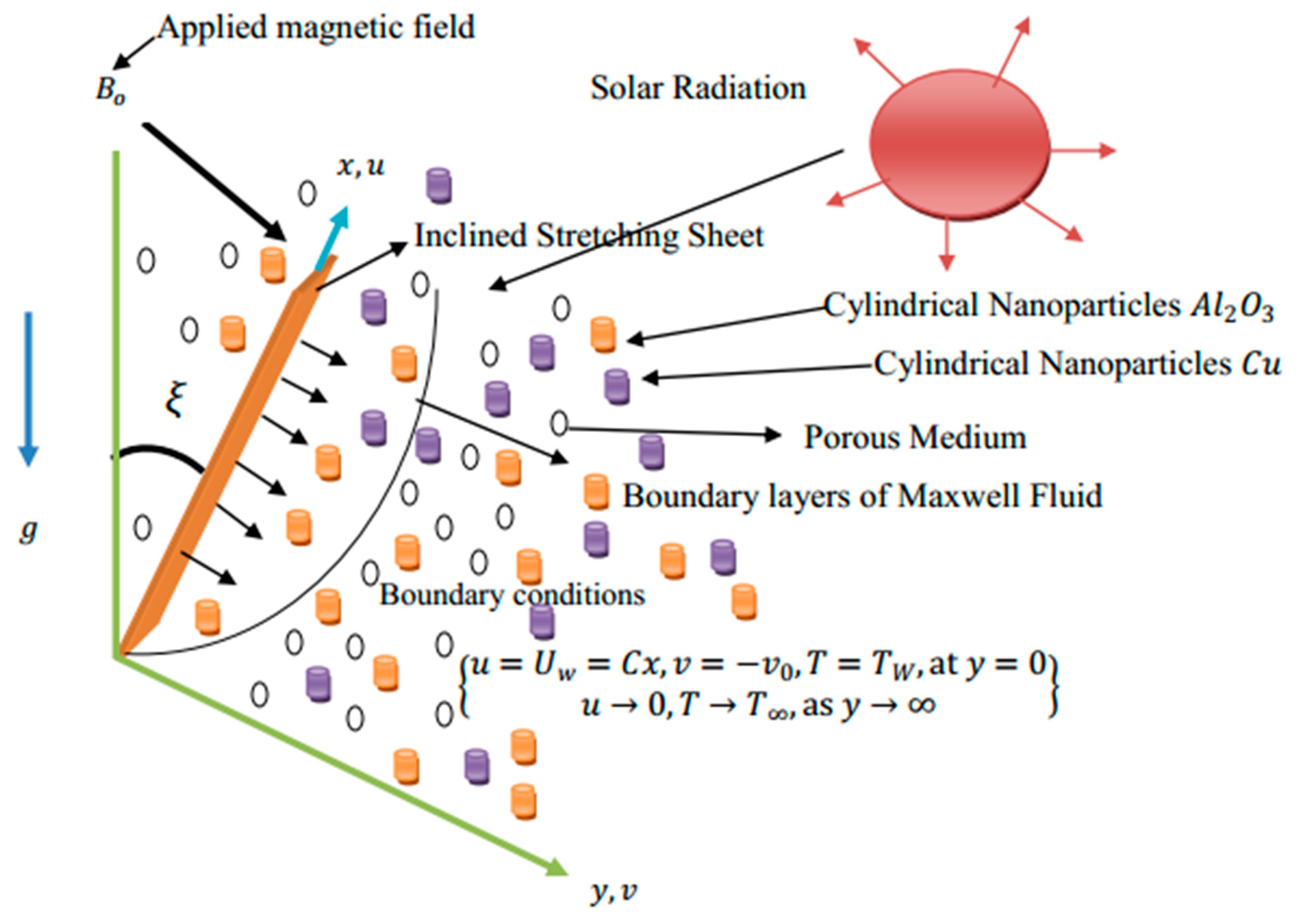
  • We have considered the two-dimensional, steady, and incompressible flow of viscous Maxwell hybrid nanofluid.
  • The hybrid nanofluid is engineered by the suspension of A l 2 O 3 - C u in ethylene glycol.
  • The fluid flow is generated due to stretching of the inclined plate at angle ξ = π / 6 .
  • The Lorentz force and porosity of the medium are encountered.
  • The solar radiation and heat generation effects in the energy equation are included.
  • The linear constructive chemical reaction in the mass equation is included.
  • The porous plate is considered to have suction effects.
  • The surface of the plate is kept at constant temperature T w and ambient temperature T with T w > T .
  • The concentration on the surface of the plate is taken as C W and concentration in a free stream as C with C w > C .
  • The flow configuration is given in Figure 1.
The following flow equations can be obtained by referring to [19,36]:
u x + v y = 0 ,
u u x + v u y = μ h n f ρ h n f   2 u y 2 β 1 u 2 2 u x 2 + v 2 2 u y 2 + 2 u v 2 u x y g ρ β T h n f ρ h n f T T C o s ξ g ρ β C h n f ρ h n f C C C o s ξ σ h n f ρ h n f B o 2 u ν h n f K o u ,
ρ C p h n f u T x + v T y = k h n f   2 T y 2 q r y + Q o ( T T )
u C x + v C y = D B   2 C y 2 R 1 ( C C )
Boundary conditions are as follows:
u = U w x = c x ,   v = v o ,   T = T w ,   C = C w         a t     y = 0 , u 0 , T T , C C ,   a s   y
The notations used in Equations (1)–(5) are defined in Table 1.
The Roseland approximation for the radiative heat flux vector q r is as follows:
q r = 4 σ 3 K R T 4 y ,
where σ is the Stefan-Boltzmann constant and K R is the mean absorption coefficient. Equation (6) right-side T 4 is given as follows:
T 4 4 T 3 T 3 T 4 .
So, Equation 6   takes the form:
q r = 16 T 3 σ 3 K R T y .
So, Equation (3) becomes:
u T x + v T y = k h n f ρ C p h n f 2 T y 2 + 16 T 3 σ ρ C p h n f 3 K R 2 T y 2 + Q ρ C p h n f ( T T ) ,
Arranging Equation (8), we obtain the following form:
u T x + v T y = k f ρ C p f k h n f k f ρ C p h n f ρ C p f + 16   T 3 σ 3 ρ C p h n f ρ C p f k f K R 2 T y 2 + + Q o ρ C p h n f ρ C p f ( T T ) .

3. Solutions Methodology

The simulation of Equations (1)–(4) along with the boundary conditions given in Equation (5) is carried out by transforming the partial differential equation into an ordinary differential equation using the bvp4c solver. The whole solution procedure adopted here is elaborated in the following sub-sections.

3.1. Similarity Variable Formulation

Equations (1)–(4) with boundary conditions given in (5) are reduced to ordinary differential equations using similarity variables given in Equation (10) used in [36] as follows:
u = c x f η , v = c ν f   f ( η ) θ η = T T T W T , ϕ η = C C C W C , η = c ν f y
Equation (10) is inserted in Equation (1); then, it satisfies automatically. The rest of the equations are given below:
μ h n f μ f ρ h n f ρ f f f 2 f f λ 1 f 2 f 2 f f f ρ β T h n f ρ β T f ρ h n f ρ f λ T θ C o s ξ ρ β C h n f ρ β C f ρ h n f ρ f λ C θ C o s ξ   σ h n f σ f ρ h n f ρ f M f μ h n f μ f K 1 f = 0 ,
k h n f k f ρ C P h n f ρ C P f + 4 3   R d ρ C P h n f ρ C P f 1 P r θ + f θ + 1 ρ C P h n f ρ C P f Q θ = 0  
1 S c ϕ + f ϕ R ϕ = 0
The considered boundary conditions are as follows:
f = S ,     f = 1 ,     θ = 1 ,   ϕ = 1     a t   η = 0 f 0 ,     θ 0 ,     ϕ 0 ,   a s   η ,
Now, we define the parameters in Table 2, which appear in Equations (11)–(14).

3.2. Quantities of Engineering

Physical quantities known as skin friction coefficient, Nusselt number, and Sherwood number are given by:
C f = 1 ρ f U W 2 μ h n f μ f u y β 1 2 u v 2 u x y + v 2 2 u y 2 y = 0 ,
N u x = x k h n f k f T W T T y y = 0 + q r y = 0 ,
S h x = D B k f C W C C y y = 0 .
Using Equation (5) in Equation (10) and performing some algebra, we have the following transformed engineering quantities:
R e x 1 / 2 C f = μ h n f μ f f 0 λ 1 f 2 0 f 0 2 f f 0 ,  
R e x 1 / 2 N u x = k h n f k f + 4 3 R d θ 0 ,  
R e x 1 / 2 N S h = ϕ 0 .
where R e x = U w x ν f is the local Reynolds number.

3.3. Solution Technique

The solutions to Equations (11)–(14) and (18)–(20) are computed using the MATLAB built-in numerical solver, which is based on the collocation Labaato-III. To use this rigorous solver, the higher-order ordinary differential equations are reduced into first-order ordinary differential equations; then, these obtained sets of first order are put into the numerical algorithm of bvp4c and solutions are obtained in graphical and tabular forms. In the following procedure, we are given:
Γ ( 1 ) = f ,   Γ ( 2 ) = f ,   Γ ( 3 ) = f ,   Γ ( 4 ) = θ ,   Γ ( 5 ) = θ ,   Γ ( 6 ) = ϕ ,   Γ ( 7 ) = ϕ
Γ Γ 1 = Γ 2 2 Γ 1 Γ 3 2 λ 1 ρ h n f ρ f Γ 1 Γ 2 Γ 3 ρ β T h n f ρ β T f ρ h n f ρ f λ Γ 4 C o s ζ ρ β C h n f ρ β C f ρ h n f ρ f λ C Γ 6 C o s ζ   σ h n f σ f ρ h n f ρ f M Γ 2 μ h n f μ f ρ h n f ρ f K 1 Γ ( 2 ) μ h n f μ f ρ h n f ρ f λ 1 ρ h n f ρ f * Γ 1 2
Γ Γ 2 = P r Γ 1 Γ 5 + 1 ρ C P h n f ρ C P f Q Γ ( 4 ) k h n f k f ρ C P h n f ρ C P f + 4 3 ρ C P h n f ρ C P f R d
Γ Γ 3 = S c ( Γ 1 Γ ( 7 ) R Γ ( 6 ) )
Boundary conditions are as follows:
Γ 1 = S ,     Γ 2 = 1 ,     Γ 4 = 1 ,     Γ 6 = 1 ,     a t   η = 0 Γ 2 0 ,     Γ 4 0 ,   Γ 6 0     a s   η .

4. Materials

In the literature, it has been noted that many researchers use single nanofluids such as aluminum oxide A l 2 O 3 and copper C u as nanoparticles in ethylene as base fluids, and mixtures of these types of nanoparticles are used in hybrid nanofluids. Upon investigation, the consideration of the use of aluminum oxide ( A l 2 O 3 ) and copper ( C u ) nanoparticles in ethylene glycol (EG) fluid can be physically justified as follows:
  • The thermal conductivity of aluminum oxide ( A l 2 O 3 ) is very high (35 W/mK), which can enhance the heat transfer rate in the fluid in a reasonable way.
  • Aluminum oxide ( A l 2 O 3 ) is chemically stable and inert in EG, reducing the likelihood of agglomeration or settlement.
  • Aluminum oxide ( A l 2 O 3 ) nanoparticles can be easily dispersed in EG due to their small size and surface charge.
  • The thermal conductivity of these C u   nanoparticles has an enormously high thermal conductivity (386 W/mK), which makes them an excellent heat transfer carrier.
  • The copper nanoparticles, C u , have a large surface-area-to-volume ratio, permitting improved heat transfer and fluid interactions.
  • The copper nanoparticles, C u , have anticorrosive properties, which are very helpful to protect the fluid and system from corrosion.
  • The ethylene glycol (EG) has a high heat capacity, so this characteristic makes it appropriate for heat transfer applications.
  • The ethylene glycol (EG) has a low viscosity, which reduces the pressure drop and the pumping power required.
  • The chemical stability of ethylene glycol (EG) is noncorrosive and this property makes it more suitable and compatible with various materials.
The combination of A l 2 O 3   and C u nanoparticles in ethylene glycol (EG) fluid can lead to improved thermal conductivity, stability, and heat transfer performance, making it suitable for various applications, such as cooling systems, heat exchangers, and thermal energy storage.
In Table 3, the thermophysical properties of nanoparticles and the base fluids are presented.
Thermophysical properties formulae for hybrid nanofluid (HN) given in [19] are given below:
k h n f k b f = n 1 k f + k s 2 n 1 ϕ 2 k b f k s 2 n 1 k b f + k s 2 + ϕ 2 k b f k s 2 k b f k f = n 1 k f + k s 2 n 1 ϕ 2 k f k s 2 n 1 k f + k s 1 + ϕ 1 k f k s 1 ρ C p h n f = ϕ 1 ρ C p s 1 + ϕ 2 ρ C p s 2 + 1 ϕ 2 1 ϕ 1 ρ C p f ρ h n f = 1 ϕ 2 1 ϕ 1 ρ f + ϕ 1 ρ s 1 + ϕ 2 ρ s 2 , σ h n f σ b f = 2 σ f + σ s 2 2 ϕ 2 σ b f σ s 2 2 σ b f + σ s 2 + ϕ 2 σ b f σ s 2 , σ b f σ f = 2 σ f + σ s 2 2 ϕ 2 σ f σ s 2 2 σ f + σ s 1 + ϕ 1 σ f σ s 1 , μ h n f μ f = 1 1 ϕ 1 2.5 1 ϕ 2 2.5 , ρ β T h n f = ϕ 1 ρ β T s 1 + ϕ 2 ρ β T s 2 + 1 ϕ 2 ( 1 ϕ 1 ) ρ β T f
where ϕ 1 and ϕ 2 are volume fractions of aluminum oxide ( A l 2 O 3 ) and Copper ( C u ), respectively. As an appropriate choice, the volume fraction of both nanoparticles is taken to be the same, which will improve the thermal performance of the fluid.

5. Results and Discussion

This section is fully concentrated on the demonstration of the numerical solutions of velocity profile f , temperature field θ , mass concentration ϕ , skin friction coefficient R e 1 / 2 C f , Nusselt number R e 1 / 2 N u , and Sherwood number R e 1 / 2 S h under the influence of parameters involved in the flow problem. The sundry numbers under the current discussion are the Maxwell fluid parameter λ 1 , modified buoyancy parameter λ C , magnetic field parameter M , buoyancy parameter λ T , Prandtl number P r , the heat generation parameter Q , dimensionless porosity parameter K 1 , radiation parameter R d , suction parameter S = v o c ν f , ( v o > 0 ) , Schmidt number S c , chemical reaction parameter R, and the volume fractions ϕ 1 ,   ϕ 2 of A l 2 O 3   nanoparticles and C u nanoparticles. Figure 2 demonstrates the variation in f against the growing values of the Maxwell fluid parameter λ 1 . It has been seen that, when λ 1 becomes enhanced, f reduces gradually. It has been noted that, when volume fractions for both types of nanoparticles are considered, the velocity goes down as compared to the velocity for the case of single-type nanoparticles. According to the physics of the concentration of nanoparticles, when it increases in a mixture, the internal resistance dominates, which results in a reduction in the velocity field. Figure 3 and Figure 4 highlight the variations in f and ϕ versus the porosity parameter K 1 . It is observed that, when K 1 rises, velocity decreases and concentration grows well. It is worthy to note that a reduction in f is due to increased K 1 that is because of an augmentation in viscous force that slows down the speed of the fluid. When there is intensification in a porous medium, it is due to the more viscous force generated in the layer, which causes the speed to reduce. Figure 4 shows that mass concentration is declining largely. When the speed of the fluid slows down, the capacity to take the mass concentration with it is difficult; therefore, the thickness of the boundary layer of concentration with the surface increases, which slows down concentration transportation. Figure 5, Figure 6 and Figure 7 report the physical effect of magnetic field parameter M on velocity f , temperature θ , and concentration ϕ . The graphs display that, when M increases, then velocity f and temperature θ decline correspondingly, as shown in Figure 5 and Figure 6, respectively. When M   upsurges, the resistive force in the motion of fluid gets stronger, which retards the movement of the fluid. The decline in the speed of the fluid flow is because of the generation of Lorentz force that is generated during the generation of current and magnetic field in normal flow fields, so the flow speed is reduced. The concentration in Figure 4 reflects that it rises rapidly, parallel to the increase in magnetic field. A noticeable point is that, when the temperature of the liquid increases, the cohesive forces between the layers get weaker, allowing easy mixing with the concertation material; hence, their transport becomes easier, as shown by the similar behavior in Figure 7.
Figure 8 and Figure 9 show the variations in f   and θ   for the increasing values of the suction parameter S . It illustrates that f increases and θ drops. The suction of the plate increases the thickness of the boundary layer due to the increased velocity of the fluid. The graphical results show the arrangement with the physics of suction parameter S . The effects of internal heat generation parameter Q to the temperature profile are illustrated in Figure 10. It can be observed that, when the heat generation parameter rises, the temperature of the fluid expands accordingly. This mechanism serves the purpose of adding internal heat generation effects to the energy equation. Figure 11 describes the fluctuations in θ for growing magnitudes of the radiation parameter R d . When it is elevated, the temperature grows rapidly. The purpose of the inclusion of solar radiation is to increase the temperature of the fluid, which leads to enrichment in heat transfer. In this study, we have noted that the addition of solar rays serves our purpose. Figure 12, Figure 13 and Figure 14 show the impact of volume fractions ϕ 1 and ϕ 2 of two types of nanoparticles in the f , θ , and ϕ , respectively. The figures show that, when volume fractions ϕ 1 and ϕ 2 are increased, velocity is condensed; on the other hand, temperature and concentration swell gradually. Physically, it is very true that, when volume fraction is augmented, this bulk of nanoparticles piles up, which slows down the speed of the fluid and enhances the temperature of the fluid. This enlarged volume of nanoparticles augments the temperature of the fluid; hence, heat transfer is upstretched. In a similar fashion, concentration transportation in the fluid also increases well with the increase in volume fractions of the nanoparticles shown in Figure 14. Figure 15 highlights the effect of the chemical reaction parameter R . When it is augmenting, concentration is declines accordingly. The concentration profile declines as the chemical reaction develops and the stretching rate constant rises. Figure 16, Figure 17 and Figure 18 are plotted to investigate the physical impact of the heat generation parameter on the skin friction coefficient R e 1 / 2 C f , Nusselt number, R e 1 / 2 N u , and Sherwood number R e 1 / 2 S h , respectively. We can note that, when the heat generation number is enhanced, R e 1 / 2 C f , R e 1 / 2 N u , and R e 1 / 2 S h grow remarkably. As per the physics of the internal generation of the heat source, the temperature of the fluid flow domain increases, ultimately leading to a rise in the heat transfer rate. In Figure 19, Figure 20 and Figure 21, the physical impact of buoyancy parameter λ T on R e 1 / 2 C f , R e 1 / 2 N u , and R e 1 / 2 S h , respectively, is shown. It has been viewed that, when λ T is enhanced, then the skin friction coefficient increases, as shown in Figure 19. The behavior of the Nusselt number, R e 1 / 2 N u , and the Sherwood number, R e 1 / 2 S h , is entirely opposite, as presented in Figure 20 and Figure 21. In Table 4, results for the rate of heat transfer θ are compared with published results for different values of P r against specific cases. There is good agreement between the current published results that ensures the validation of the current model.

6. Conclusions

In the current proposed mechanism, the mathematical model for the simulation of Maxwell hybrid nanofluid under Lorentz force is carried out. The hybrid nanofluid in the present study is prepared by mixing aluminum oxide and copper nanoparticles in ethylene glycol. The fluid flow is induced by the linear stretching of the inclined plate embedded in a porous medium. The current phenomenon involves thermal radiation, heat generation, suction of the plate, and chemical reaction effects. The cylindrical-shaped nanoparticles are taken into account. The key outcomes of the study are summarized below:
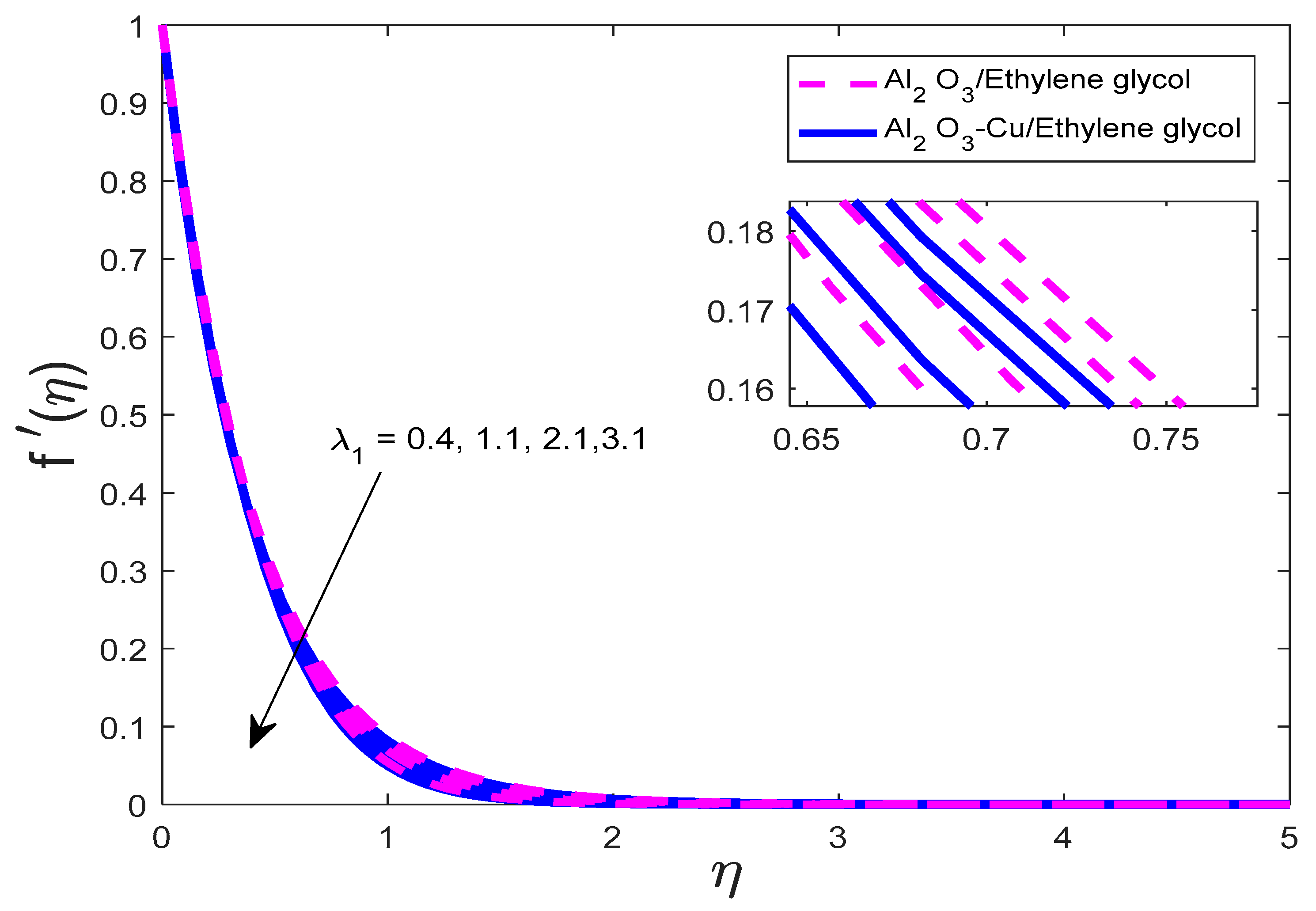
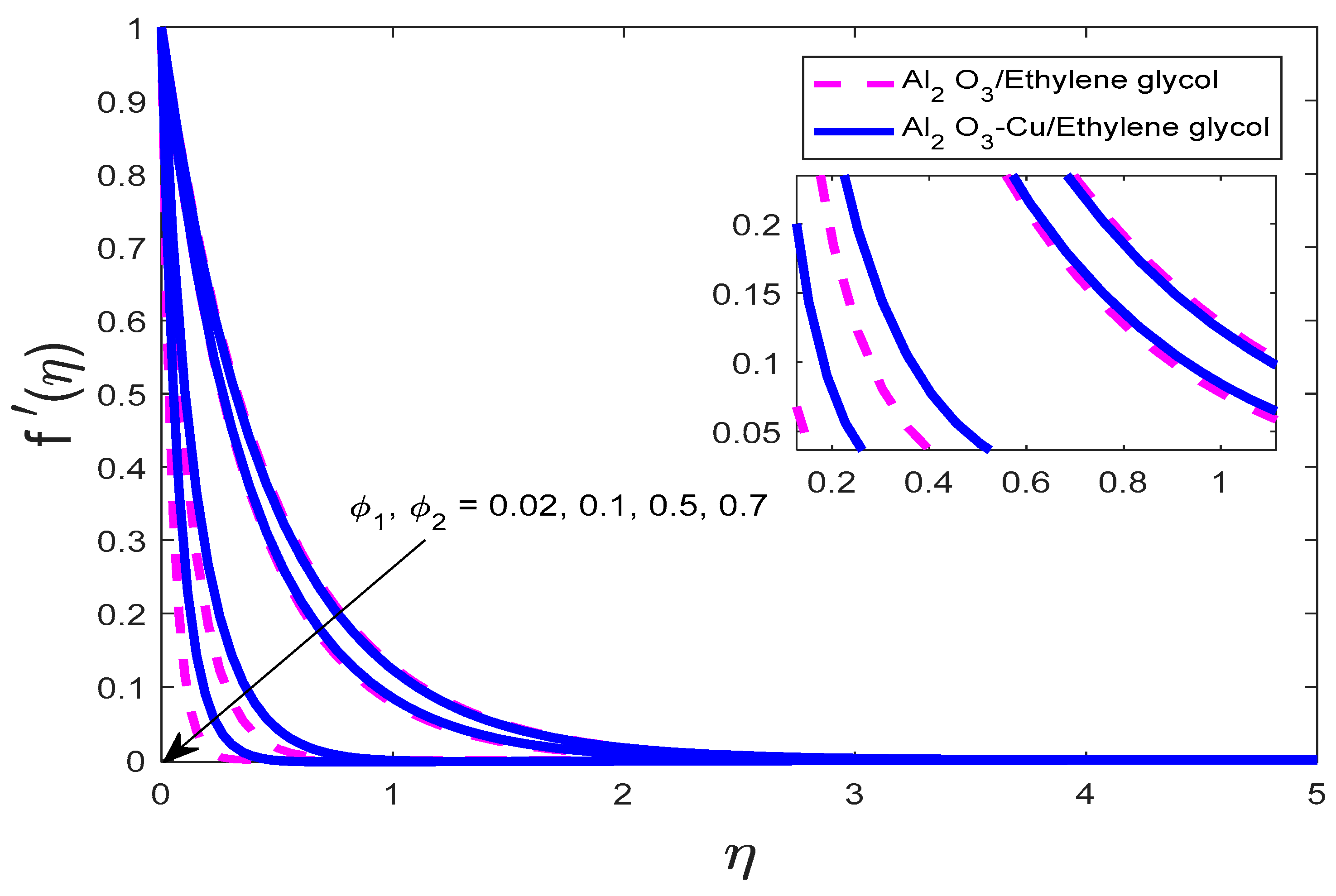
  • The velocity field decreases for increasing magnetic field parameter, Maxwell fluid parameter, volume fractions of nanoparticles, and porosity parameter but increases for increasing suction parameter.
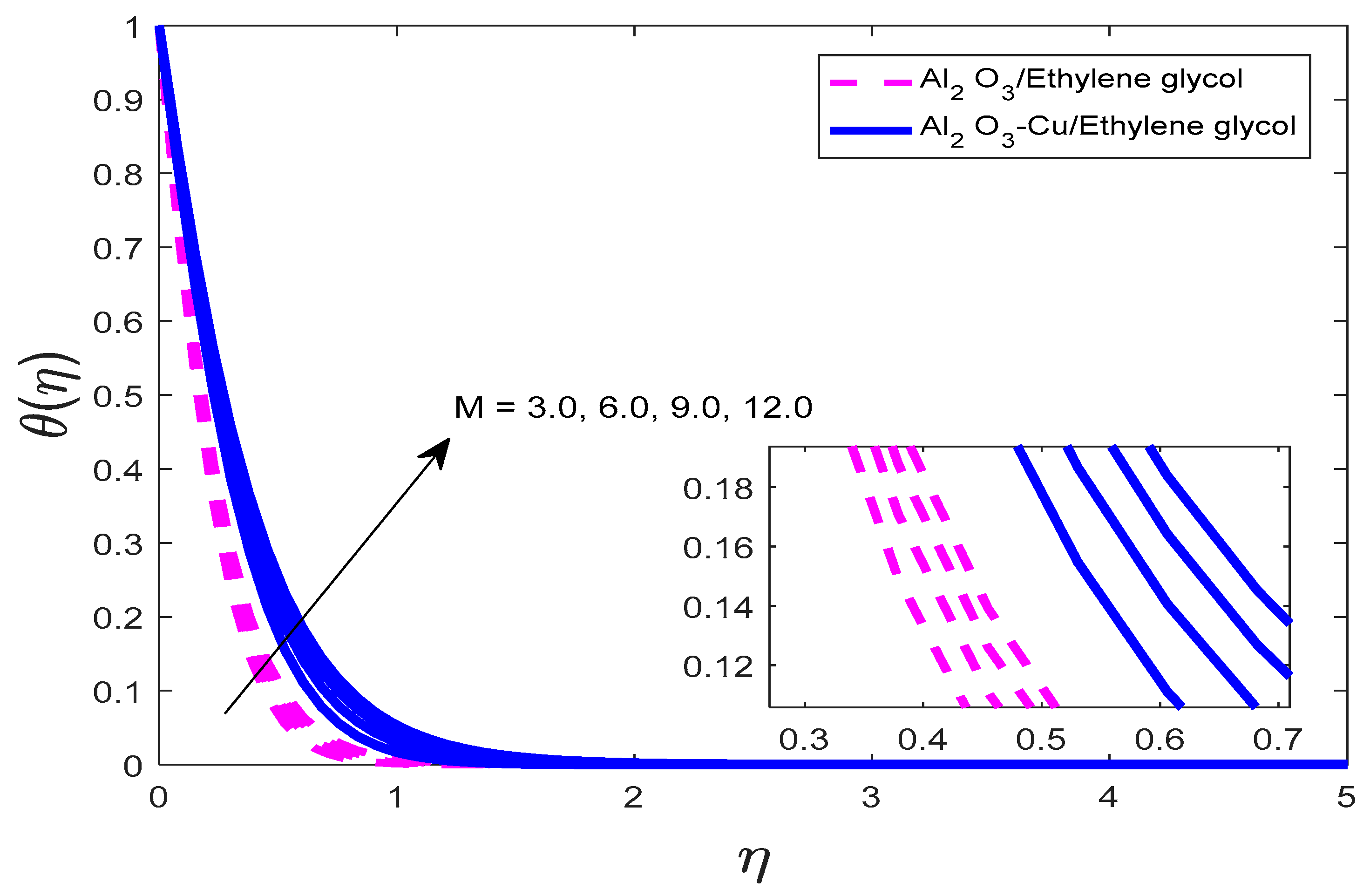
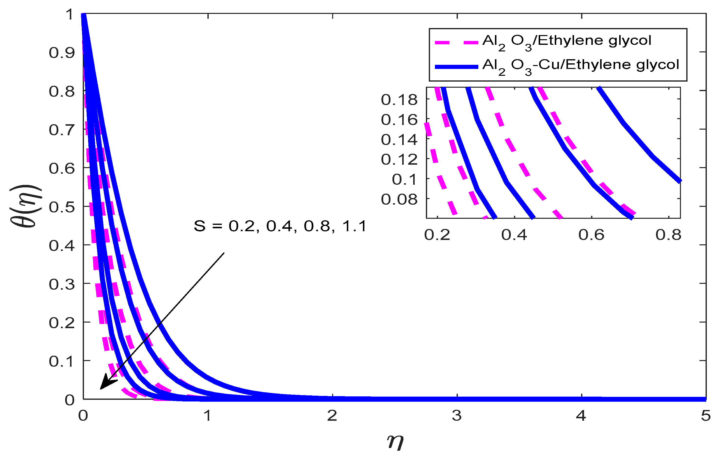
  • The temperature decreases with increasing values of magnetic field force and suction parameters but becomes higher with increasing values of radiation parameters, heat generation parameters, and volume fractions of the nanoparticles.
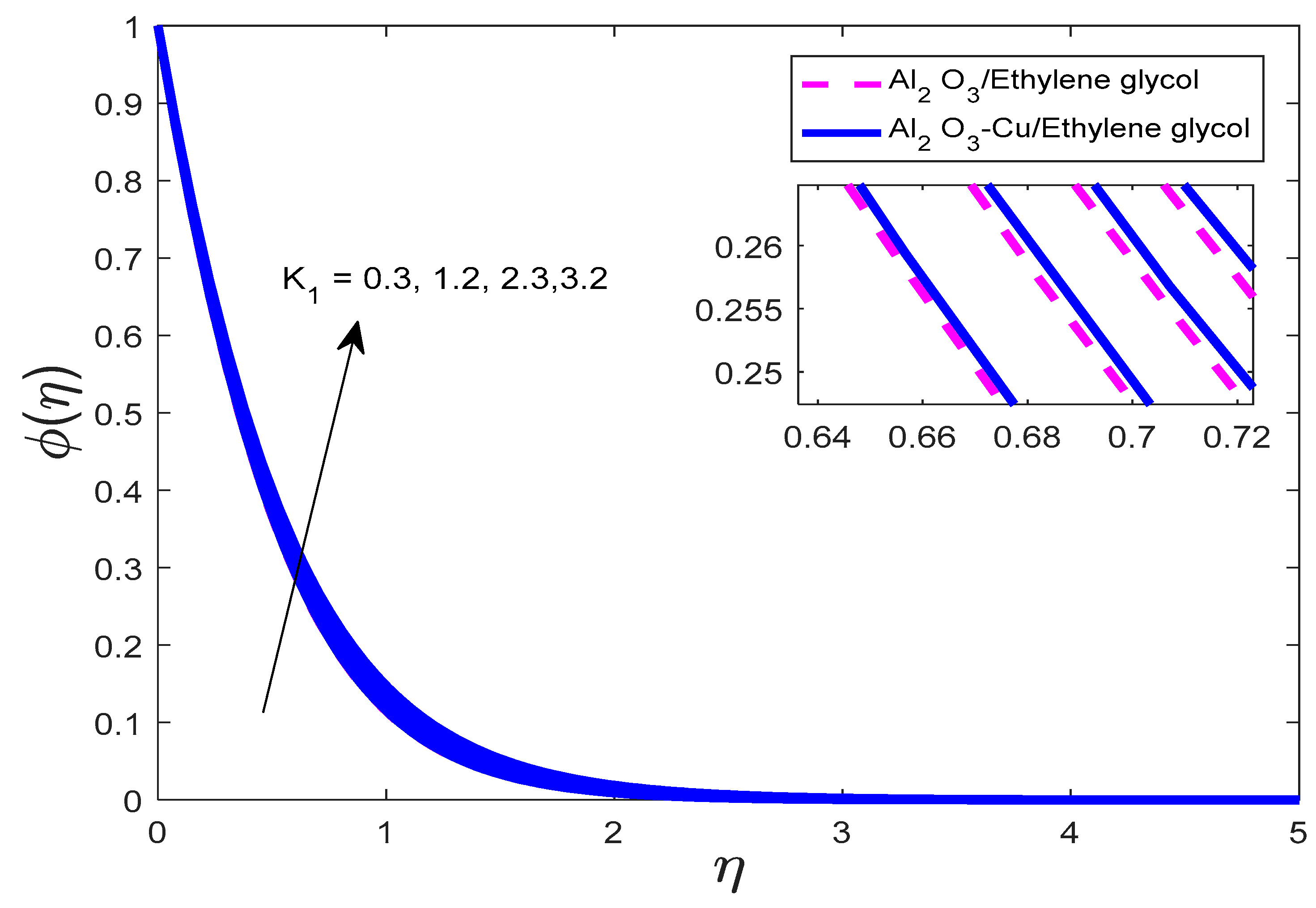
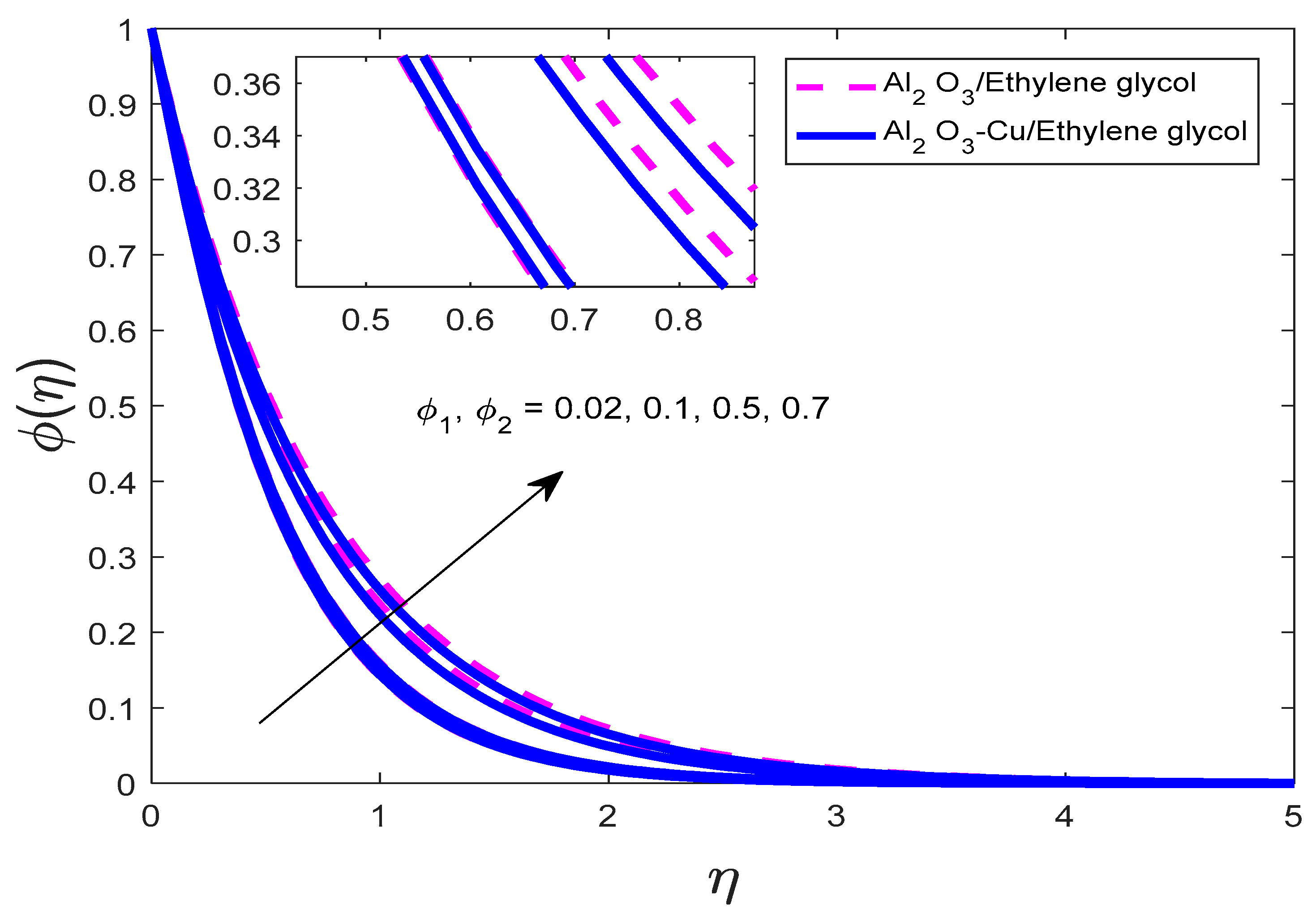
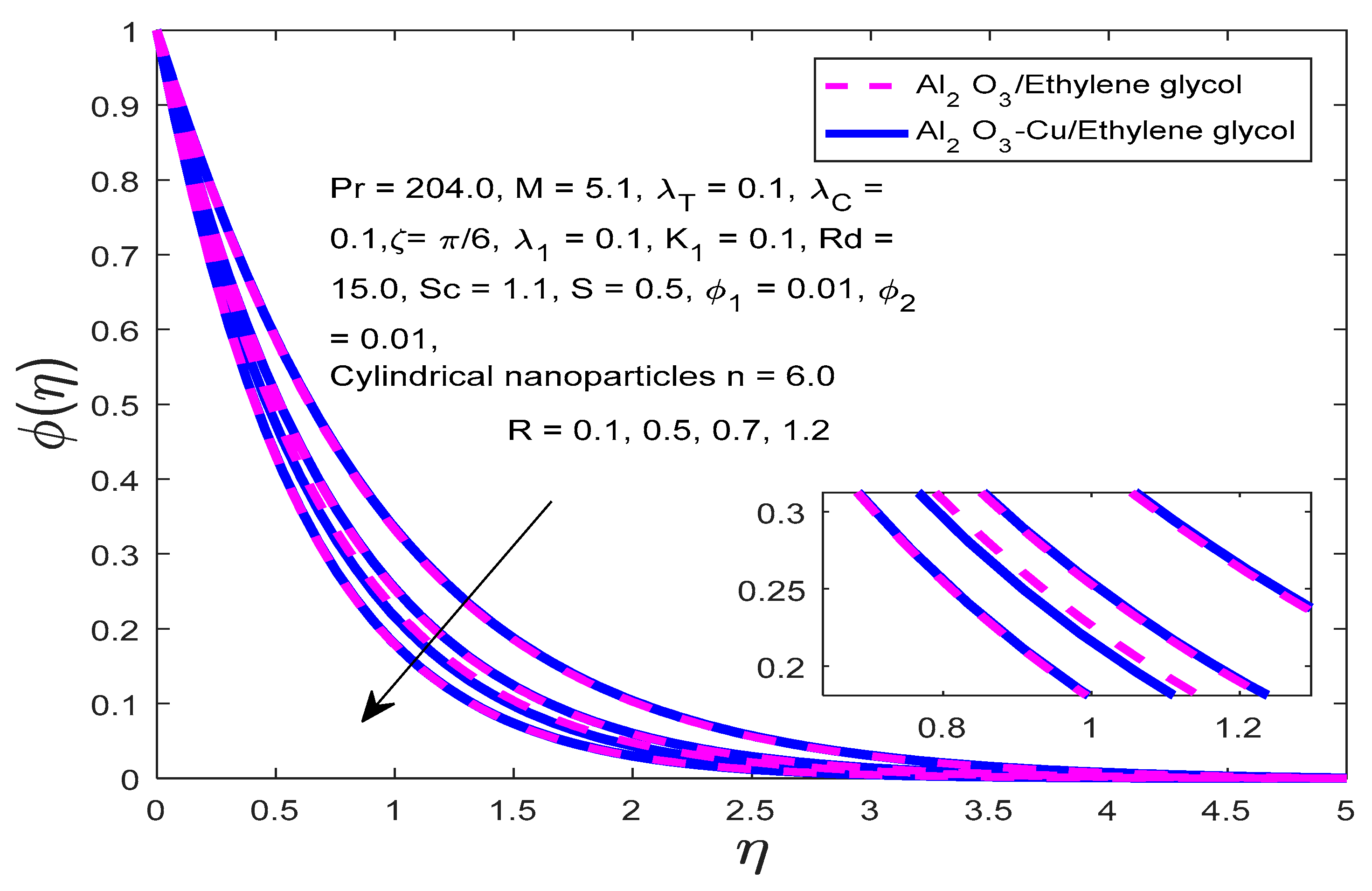
  • The concentration profile surges with increasing magnitudes of magnetic force parameter, porosity parameter, and volume fractions but decreases for increasing chemical reaction parameter and suction parameter.
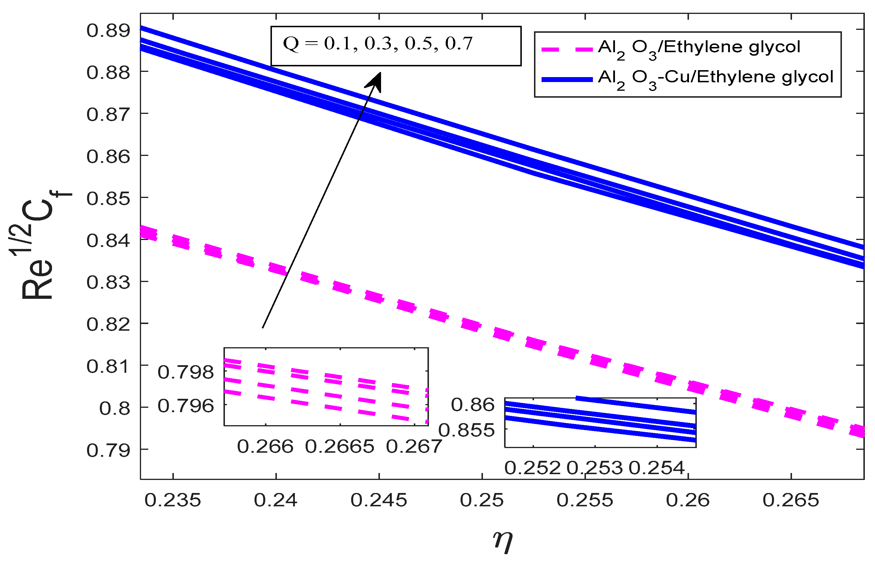
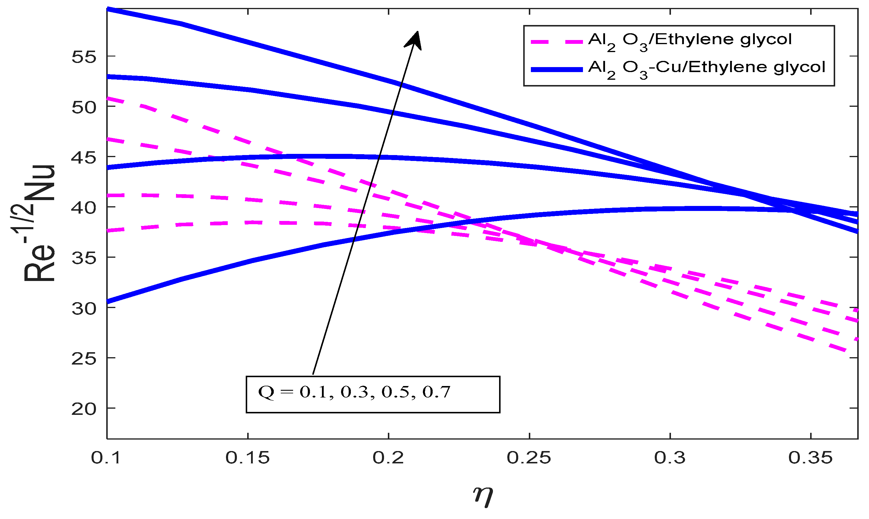
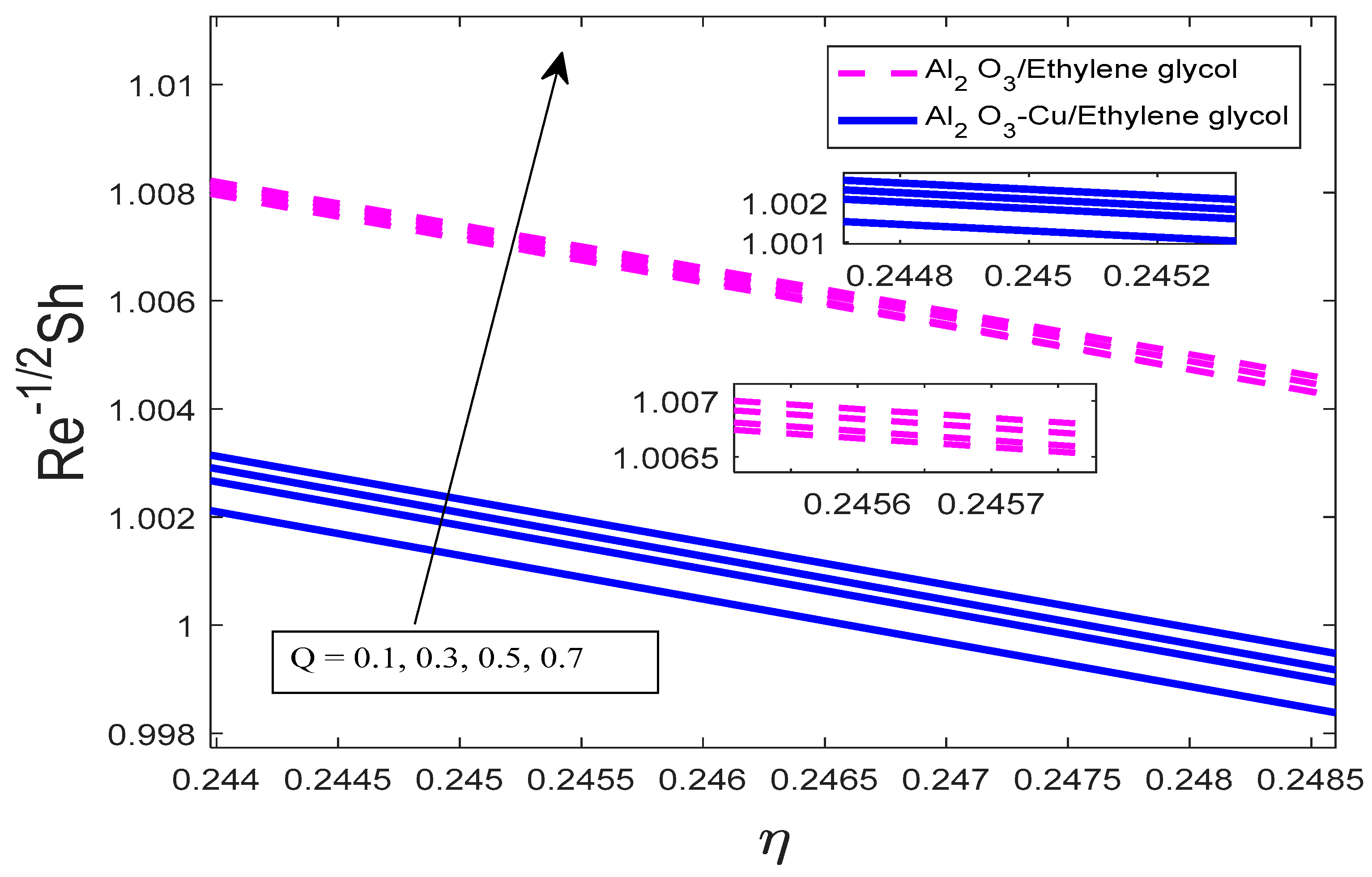
  • It has been noted that, when the heat generation parameter increases, the skin friction coefficient, Nusselt number, and Sherwood number increase well.
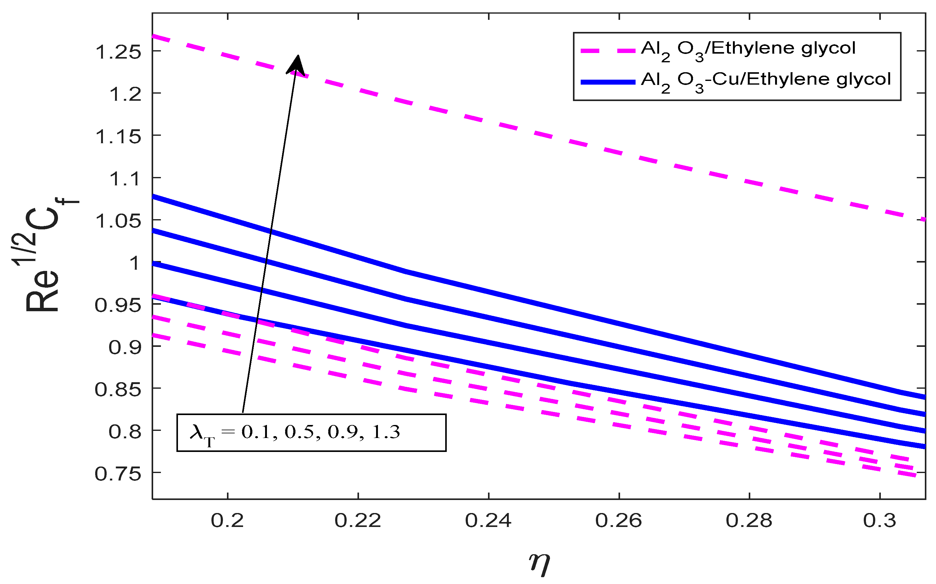
  • As the buoyancy parameter rises, skin friction increases but the Nusselt number and Sherwood number decline a lot.
The validation of the current results is given by comparing the present solution with those previously published for specific cases.

7. Limitations of the Current Study

The limitations of the currently proposed study are given below:
  • The current study is limited to the Maxwell hybrid nanofluid engineered by a suspension of A l 2 O 3 - C u in ethylene glycol.
  • Here, the single-phase model for hybrid nanofluid is considered.
  • In the present study, empirical correlations for effective viscosity and thermal conductivity are encountered.
  • In the current research, heat generation, thermal radiation, chemical reactions, porous mediums, and applied magnetic fields are considered.
  • The flow geometry is inclined at angle ζ = π / 6 , and permeable and mixed convection are considered.
  • The value of Prandtl is taken as 204 as we have taken ethylene glycol as the base fluid. Further, the ranges of other parameter are taken as below as an appropriate choice. In the current investigations, the ranges for the parameters are given as 0.1 λ 1 3.1 ,   0.1 K 1 3.2 ,   0.1 M 12 ,   0.1 S 1.1 ,   0.1 S c 2.1 ,   0.1 Q 0.7 ,   0.1 R d 15.0 ,   0.01 ϕ 1 ,   ϕ 2 0.7 , 0.1 λ T 1.3 ,   0.1 Q 0.5 .

8. Future Recommendations

  • This study can be extended to non-Newtonian fluid flow problems with the same geometry but different characteristics.
  • This study is carried out for a single-phase model; this can be investigated for a two-phase model of nanofluids, hybrid nanofluids, and ternary nanofluids and can be embedded in climate modeling.
  • In the future, this can be extended to the impact of reduced gravity and shape factors of nanoparticles on other non-Newtonian fluid flow problems using a single-phase model for nanofluid.
  • This study can be carried out for hybridized nanofluid flow using multi-walled carbon nanotubes (MWCNTs) and single-walled carbon nanotubes (SWCNTs) as nanoparticles with water and ethylene glycol as base fluids.

Author Contributions

Conceptualization, M.B.J. and A.A.; Methodology, M.B.J. and A.A.; Software, M.B.J., A.A. and N.A.A.; Validation, M.B.J., A.A. and N.A.A.; Formal analysis, A.A. and N.A.A.; Investigation, A.A. and N.A.A.; Resources, M.B.J.; Data curation, A.A.; Writing—original draft, M.B.J. and A.A.; Writing—review & editing, A.A. and N.A.A.; Visualization, M.B.J., A.A. and N.A.A.; Supervision, M.B.J. and A.A.; Project administration, M.B.J.; Funding acquisition, M.B.J. All authors have read and agreed to the published version of the manuscript.

Funding

This work was supported and funded by the Deanship of Scientific research at Imam Mohammad Ibn Saud Islamic University (IMSIU) (grant number IMSIU-RPP2023116).

Data Availability Statement

The original contributions presented in this study are included in the article; further inquiries can be directed to the corresponding author/s.

Acknowledgments

This work was supported and funded by the Deanship of Scientific research at Imam Mohammad Ibn Saud Islamic University (IMSIU) (grant number IMSIU-RPP2023116).

Conflicts of Interest

All authors declare no conflicts of interest.

References

  1. Choi, S.U.; Eastman, J.A. Enhancing Thermal Conductivity of Fluids with Nanoparticles; Argonne National Lab. (ANL): Argonne, IL, USA, 1995; Volume 231, pp. 99–106. [Google Scholar]
  2. Akoh, H.; Tsukasaki, Y.; Tasaki, A.; Yatsuya, S. Magnetic properties of ferromagnetic ultrafine particles prepared by vacuum. J. Cryst. Growth 1978, 45, 495–500. [Google Scholar] [CrossRef]
  3. Eastman, J.A.; Choi, U.S.; Li, S.; Thompson, L.J.; Lee, S. Enhanced thermal conductivity through the development of nanofluids. Mater. Res. Soc. Symp. Proc. 1997, 457, 3–11. [Google Scholar] [CrossRef]
  4. Lee, S.; Choi, S.; Li, S.; Eastman, J. Measuring thermal conductivity of fluids containing oxide nanoparticles. J. Heat Transf. 1999, 121, 280–289. [Google Scholar] [CrossRef]
  5. Eastman, J.A.; Choi, S.U.S.; Li, S.; Yu, W.; Thompson, L.J. Anomalously increased effective thermal conductivities of ethylene glycol-based nanofluids containing copper nanoparticles. Appl. Phys. Lett. 2001, 78, 718–720. [Google Scholar] [CrossRef]
  6. Buongiorno, J.; Hu, W. Nanofluid coolants for advanced nuclear power plants. In Proceedings of the ICAPP 2005, Seoul, Republic of Korea, 15–19 May 2005; Volume 5, pp. 15–19. [Google Scholar]
  7. Buongiorno, J. Convective Transport in Nanofluids. J. Heat Transf. 2006, 128, 240–245. [Google Scholar] [CrossRef]
  8. Tiwari, R.K.; Das, M.K. Heat transfer augmentation in a two-sided lid-driven differentially heated square cavity utilizing nanofluids. Int. J. Heat Mass Transf. 2007, 50, 2002–2018. [Google Scholar] [CrossRef]
  9. Sidik, N.A.C.; Adamu, I.M.; Jamil, M.M. Preparation methods and thermal performance of hybrid nanofluids. J. Adv. Res. Mater. Sci. 2019, 56, 1–10. [Google Scholar]
  10. Choi, S.U. Nanofluids: A new field of scientific research and innovative applications. Heat Transf. Eng. 2008, 29, 429–431. [Google Scholar] [CrossRef]
  11. Turcu, R.; Darabont, A.L.; Nan, A.; Aldea, N.; Macovei, D.; Bica, D.; Vekas, L.; Pana, O.; Soran, M.L.; Koos, A.A.; et al. New polypyrrole-multiwall carbon nanotubes hybrid materials. J. Optoelectron. Adv. Mater. 2006, 8, 643–647. [Google Scholar]
  12. Jha, N.; Ramaprabhu, S. Thermal conductivity studies of metal dispersed multiwalled carbon nanotubes in water and ethylene glycol based nanofluids. J. Appl. Phys. 2009, 106, 84317. [Google Scholar] [CrossRef]
  13. Kshirsagar, D.P.; Venkatesh, M.A. A review on hybrid nanofluids for engineering applications. Mater. Today Proc. 2021, 44, 744–755. [Google Scholar] [CrossRef]
  14. Sheikholeslami, M.; Abohamzeh, E.; Ebrahimpour, Z.; Said, Z. 8—Brief overview of the applications of hybrid nanofluids. In Hybrid Nanofluids; Elsevier: Amsterdam, The Netherlands, 2022; pp. 171–202. [Google Scholar]
  15. Jeelani, M.B.; Abbas, A. Thermal efficiency of spherical nanoparticles Al2O3-Cu dispersion in ethylene glycol via the MHD non-Newtonian Maxwell fluid model past the stretching inclined sheet with suction effects in a porous space. Processes 2023, 11, 2842. [Google Scholar] [CrossRef]
  16. Jeelani, M.B.; Abbas, A. Al2O3-Cu\Ethylene glycol-based magnetohydrodynamic non-Newtonian Maxwell hybrid nanofluid flow with suction effects in a porous space: Energy saving by solar radiation. Symmetry 2023, 15, 1794. [Google Scholar] [CrossRef]
  17. Abbas, A.; Hussanan, A.; Anwar, F.; Obalalu, A.M.; Almeshaal, M.A.; Palaniappan, M.; Choubani, K.; Kolsi, L.; Aslam, M. Thermal analysis of AA7075-AA7072/methanol via Williamson hybrid nanofluid model past thin needle: Effects of Lorentz force and irregular heat rise/fall. Case Stud. Therm. Eng. 2024, 53, 103883. [Google Scholar] [CrossRef]
  18. Abbas, A.; Hussanan, A.; Obalalu, A.M.; Kriaa, K.; Maatki, C.; Hadrich, B.; Aslam, M.; Kolsi, L. Effect of non-uniform heat rise/fall and porosity on MHD Williamson hybrid nanofluid flow over incessantly moving thin needle. Heliyon 2024, 10, e23588. [Google Scholar] [CrossRef] [PubMed]
  19. Rauf, A.; Hussain, F.; Mushtaq, A.; Shah, N.A.; Ali, M.R. MHD mixed convection flow for Maxwell Hybrid nanofluid with Soret, Dufour and Morphology effects. Arab. J. Chem. 2023, 16, 104965. [Google Scholar] [CrossRef]
  20. Kumar, M.A.; Reddy, Y.D. Computational modelling of radiative Maxwell fluid flow over a stretching sheet containing nanoparticles with chemical reaction. J. Indian Chem. Soc. 2023, 100, 100877. [Google Scholar] [CrossRef]
  21. Blasius, H. Grenzschichten in Flüssigkeiten mit Kleiner Reibung; Druck von BG Teubner: Leipzig, Germany, 1907. [Google Scholar]
  22. Sakiadis, B.C. Boundary-layer behavior on continuous solid surfaces: II. The boundary layer on a continuous flat surface. AiChE J. 1961, 7, 221–225. [Google Scholar]
  23. Cortell, R. A numerical tackling on Sakiadis flow with thermal radiation. Chin. Phys. Lett. 2008, 25, 1340. [Google Scholar] [CrossRef]
  24. Khan, W.A.; Pop, I. Boundary-layer flow of a nanofluid past a stretching sheet. Int. J. Heat Mass Transf. 2010, 53, 2477–2483. [Google Scholar] [CrossRef]
  25. Abbas, A.; Ijaz, I.; Ashraf, M.; Ahmad, H. Combined effects of variable density and thermal radiation on MHD Sakiadis flow. Case Stud. Therm. Eng. 2021, 28, 101640. [Google Scholar] [CrossRef]
  26. Alabdulhadi, S.; Waini, I.; Ahmed, S.E.; Ishak, A. Hybrid nanofluid flow and heat transfer past an inclined surface. Mathematics 2021, 9, 3176. [Google Scholar] [CrossRef]
  27. Anuar, N.S.; Bachok, N.; Pop, I. Influence of buoyancy force on Ag-MgO/water hybrid nanofluid flow in an inclined permeable stretching/shrinking sheet. Int. Commun. Heat Mass Transf. 2021, 123, 105236. [Google Scholar] [CrossRef]
  28. Khan, U.; Waini, I.; Zaib, A.; Ishak, A.; Pop, I. MHD mixed convection hybrid nanofluids flow over a permeable moving inclined flat plate in the presence of thermophoretic and radiative heat flux effects. Mathematics 2022, 10, 1164. [Google Scholar] [CrossRef]
  29. Waini, I.; Ishak, A.; Groşan, T.; Pop, I. Mixed convection of a hybrid nanofluid flow along a vertical surface embedded in a porous medium. Int. Commun. Heat Mass Transf. 2020, 114, 104565. [Google Scholar] [CrossRef]
  30. Eid, M.R.; Nafe, M.A. Thermal conductivity variation and heat generation effects on magneto-hybrid nanofluid flow in a porous medium with slip condition. Waves Random Complex Media 2022, 32, 1103–1127. [Google Scholar] [CrossRef]
  31. Algehyne, E.A.; El-Zahar, E.R.; Elhag, S.H.; Bayones, F.S.; Nazir, U.; Sohail, M.; Kumam, P. Investigation of thermal performance of Maxwell hybrid nanofluid boundary value problem in vertical porous surface via finite element approach. Sci. Rep. 2022, 12, 2335. [Google Scholar] [CrossRef]
  32. Gul, T.; Mukhtar, S.; Alghamdi, W.; Tag Eldin, E.; Yassen, M.F.; Guedri, K. The radiative flow of the thin-film Maxwell hybrid nanofluids on an inclined plane in a porous space. Front. Energy Res. 2022, 10, 970293. [Google Scholar] [CrossRef]
  33. Mebarek-Oudina, F.; Chabani, I.; Vaidya, H.; Ismail, A.A.I. Hybrid-nanofluid magneto-convective flow and porous media contribution to entropy generation. Int. J. Numer. Methods Heat Fluid Flow 2024, 34, 809–836. [Google Scholar] [CrossRef]
  34. Sagheer, S.; Farooq, U.; Hussain, M. Non-similar investigation of enhanced thermal efficiency of Maxwell based hybrid nanofluid (MoS2 + ZnO) across a linearly stretched surface. J. Magn. Magn. Mater. 2023, 565, 170285. [Google Scholar] [CrossRef]
  35. Rashad, A.M.; Nafe, M.A.; Eisa, D.A. Variation of thermal conductivity and heat on magnetic maxwell hybrid nanofluid viscous flow in a porous system with higher-order chemical react. Spec. Top. Rev. Porous Media Int. J. 2023, 14, 17–32. [Google Scholar] [CrossRef]
  36. Devi, S.A.; Devi, S.S.U. Numerical investigation of hydromagnetic hybrid Cu–Al2O3/water nanofluid flow over a permeable stretching sheet with suction. Int. J. Nonlinear Sci. Numer. Simul. 2016, 17, 249–257. [Google Scholar] [CrossRef]
  37. Safdar, R.; Jawad, M.; Hussain, S.; Imran, M.; Akgül, A.; Jamshed, W. Thermal radiative mixed convection flow of MHD Maxwell nanofluid: Implementation of Buongiorno’s model. Chin. J. Phys. 2022, 77, 1465–1478. [Google Scholar] [CrossRef]
  38. Ahmed, A.; Khan, M.; Irfan, M.; Ahmed, J. Transient MHD flow of Maxwell nanofluid subject to non-linear thermal radiation and convective heat transport. Appl. Nanosci. 2020, 10, 5361–5373. [Google Scholar] [CrossRef]
  39. Mukhtar, T.; Jamshed, W.; Aziz, A.; Al-Kouz, W. Computational investigation of heat transfer in a flow subjected to magnetohydrodynamic of Maxwell nanofluid over a stretched flat sheet with thermal radiation. Numer. Methods Partial. Differ. Equ. 2023, 39, 3499–3519. [Google Scholar] [CrossRef]
  40. Hassan, A.; Hussain, A.; Arshad, M.; Haider, Q.; Althobaiti, A.; Elagan, S.K.; Alqurashi, M.S.; Abdelmohimen, M.A.H. Heat transport investigation of hybrid nanofluid (Ag-CuO) porous medium flow: Under magnetic field and Rosseland radiation. Ain Shams Eng. J. 2022, 13, 101667. [Google Scholar] [CrossRef]
Figure 1. Flow structure.
Processes 12 01196 g001
Figure 2. Evaluation of impact of λ 1 on f when P r = 204 , M = 5.2 ,   λ T = 0.2 ,   λ C = 0.1 ,   K 1 = 0.1 , R d = 0.1 , Q = 0.2 , S = 0.5 , S c = 5.0 , R = 0.1 ,   ϕ 1 = 0.01 ,   ϕ 2 = 0.01 , n = 6.0 at ζ = π / 6 .
Processes 12 01196 g002
Figure 3. Evaluation of impact of K 1 on f when P r = 204 , M = 2.0 ,   λ T = 0.2 ,   λ C = 0.1 ,   λ 1 = 0.1 , R d = 0.2 , Q = 0.1 , S = 0.5 , S c = 2.0 , R = 0.1 , ϕ 1 = 0.01 ,   ϕ 2 = 0.01 , n = 6.0 at ζ = π / 6 .
Processes 12 01196 g003
Figure 4. Evaluation of impact of K 1 on ϕ when P r = 204 , M = 2.0 ,   λ T = 0.2 ,   λ C = 0.1 ,   λ 1 = 0.1 , R d = 0.2 , Q = 0.1 , S = 0.5 , S c = 2.0 , R = 0.1 , ϕ 1 = 0.01 ,   ϕ 2 = 0.01 , n = 6.0 at ζ = π / 6 .
Processes 12 01196 g004
Figure 5. Evaluation of impact of M on f when P r = 204 ,   λ 1 = 0.6 ,   λ T = 0.2 ,   λ C = 0.2 ,   K 1 = 0.1 , R d = 0.3 , Q = 0.1 , S = 0.5 , S c = 5.0 , R = 0.1 ,   ϕ 1 = 0.01 ,   ϕ 2 = 0.01 , n = 6.0 at ζ = π / 6 .
Processes 12 01196 g005
Figure 6. Evaluation of impact of M on θ when P r = 204 ,   λ 1 = 0.6 ,   λ T = 0.2 , λ C = 0.2 ,   K 1 = 0.1 , R d = 0.3 , Q = 0.1 , S = 0.5 , S c = 5.0 , R = 0.1 ,   ϕ 1 = 0.01 , ϕ 2 = 0.01 , n = 6.0 at ζ = π / 6 .
Processes 12 01196 g006
Figure 7. Evaluation of impact of M on ϕ when P r = 204 ,   λ 1 = 0.6 ,   λ T = 0.2 ,   λ C = 0.2 ,   K 1 = 0.1 , R d = 0.3 , Q = 0.1 , S = 0.5 , S c = 5.0 , R = 0.1 ,   ϕ 1 = 0.01 ,   ϕ 2 = 0.01 , n = 6.0 at ζ = π / 6 .
Processes 12 01196 g007
Figure 8. Evaluation of impact of S on f when P r = 204 , M = 4.0 ,   λ T = 0.1 , δ = 0.3 , λ C = 0.3 ,   λ 1 = 1.0 ,   K 1 = 0.1 , R d = 10.0 , S c = 2.0 , R = 0.1 ,   ϕ 1 = 0.01 ,   ϕ 2 = 0.01 , n = 6.0 at ζ = π / 6 .
Processes 12 01196 g008
Figure 9. Evaluation of impact of S on θ when P r = 204 , M = 4.0 ,   λ T = 0.1 , Q = 0.3 , λ C = 0.3 ,   λ 1 = 1.0 ,   K 1 = 0.1 , R d = 10.0 , S c = 2.0 , R = 0.1 ,   ϕ 1 = 0.01 ,   ϕ 2 = 0.01 , n = 6.0 at ζ = π / 6 .
Processes 12 01196 g009
Figure 10. Evaluation of impact of Q on ϕ when P r = 204 , M = 0.1 , λ T = 0.1 , λ C = 0.1 ,   λ 1 = 0.1 ,   K 1 = 1.1 , R d = 15.0 , S c = 2.1 , R = 0.1 , S = 0.1 ,   ϕ 1 = 0.01 ,   ϕ 2 = 0.01 , n = 6.0 at ζ = π / 6 .
Processes 12 01196 g010
Figure 11. Evaluation of impact of R d on θ when P r = 204 , M = 3.0 , λ T = 0.2 , Q = 0.3 , λ C = 0.1 ,   λ 1 = 1.0 , R d = 0.2 , S = 0.5 , S c = 2.0 , R = 0.1 ,   ϕ 1 = 0.01 ,   ϕ 2 = 0.01 , n = 6.0 at ζ = π / 6 .
Processes 12 01196 g011
Figure 12. Evaluation of impact of ϕ 1 , ϕ 2 on f when P r = 204 , M = 5.0 ,   λ T = 0.3 , Q = 0.5 , λ C = 0.1 , λ 1 = 0.1 ,   K 1 = 0.1 , R d = 13.0 , S c = 2.0 , R = 0.1 , S = 0.5 , n = 6.0 at ζ = π / 6 .
Processes 12 01196 g012
Figure 13. Evaluation of impact of ϕ 1 , ϕ 2 on θ when P r = 204 , M = 5.0 , λ T = 0.3 , Q = 0.5 , λ C = 0.1 ,   λ 1 = 0.1 ,   K 1 = 0.1 , R d = 13.0 , S c = 2.0 , R = 0.1 , S = 0.5 , n = 6.0 at ζ = π / 6 .
Processes 12 01196 g013
Figure 14. Evaluation of impact of ϕ 1 , ϕ 2 on ϕ when P r = 204 , M = 5.0 ,   λ T = 0.3 , Q = 0.5 , λ C = 0.1 , λ 1 = 0.1 ,   K 1 = 0.1 , R d = 13 , n = 6.0 at ζ = π / 6 .
Processes 12 01196 g014
Figure 15. Evaluation of impact of R on ϕ when P r = 204 , M = 5.0 ,   λ T = 0.1 , δ = 0.1 , λ C = 0.3 , λ 1 = 0.1 ,   K 1 = 0.1 , R d = 10.0 , S c = 1.2 , S = 0.4 ,   ϕ 1 = 0.01 ,   ϕ 2 = 0.01 , n = 6.0 at ζ = π / 6 .
Processes 12 01196 g015
Figure 16. Evaluation of impact of Q on R e 1 / 2 C f when P r = 204 , M = 0.1 ,   λ T = 0.1 , λ C = 0.1 ,   λ 1 = 0.1 ,   K 1 = 1.1 , R d = 15.0 , S c = 2.1 , R = 0.1 , S = 0.1 ,   ϕ 1 = 0.01 ,   ϕ 2 = 0.01 , n = 6.0 at ζ = π / 6 .
Processes 12 01196 g016
Figure 17. Evaluation of impact of Q on R e 1 / 2 N u when P r = 204 , M = 0.1 ,   λ T = 0.1 , λ C = 0.1 , λ 1 = 0.1 ,   K 1 = 1.1 , R d = 15.0 , S c = 2.1 , R = 0.1 , S = 0.1 ,   ϕ 1 = 0.01 ,   ϕ 2 = 0.01 , n = 6.0 at ζ = π / 6 .
Processes 12 01196 g017
Figure 18. Evaluation of impact of Q on R e 1 / 2 S h when P r = 204 , M = 0.1 , λ T = 0.1 , λ C = 0.1 ,   λ 1 = 0.1 ,   K 1 = 1.1 , R d = 15.0 , S c = 2.1 , R = 0.1 , S = 0.1 ,   ϕ 1 = 0.01 ,   ϕ 2 = 0.01 , n = 6.0 at ζ = π / 6 .
Processes 12 01196 g018
Figure 19. Evaluation of impact of λ T on R e 1 / 2 C f when P r = 204 , M = 0.1 , Q = 0.1 , λ C = 0.1 ,   λ 1 = 0.1 , K 1 = 1.1 , R d = 15.0 , S c = 2.1 , R = 0.1 , S = 0.1 ,   ϕ 1 = 0.01 , ϕ 2 = 0.01 , n = 6.0 at ζ = π / 6 .
Processes 12 01196 g019
Figure 20. Evaluation of impact of λ T on R e 1 / 2 N u when P r = 204 , M = 0.1 , Q = 0.1 , λ C = 0.1 ,   λ 1 = 0.1 ,   K 1 = 1.1 , R d = 15.0 , S c = 2.1 , R = 0.1 , S = 0.1 , ϕ 1 = 0.01 , ϕ 2 = 0.01 , n = 6.0 at ζ = π / 6 .
Processes 12 01196 g020
Figure 21. Evaluation of impact of λ T on R e 1 / 2 S h when P r = 204 , M = 0.1 , Q = 0.1 , λ C = 0.1 ,   λ 1 = 0.1 ,   K 1 = 1.1 , R d = 15.0 , S c = 2.1 , R = 0.1 , S = 0.1 ,   ϕ 1 = 0.01 ,   ϕ 2 = 0.01 , n = 6.0 at ζ = π / 6 .
Processes 12 01196 g021
Table 1. Definition of notations used in Equations (1)–(5).
u , v Velocity components in horizontal and normal directions
ξ Angle of inclination
ν f base fluid kinematic viscosity
R 1 Chemical reaction constant
B o Magnetic field strength
σ f electrical conductivity of base fluid
β T f ,   β C f Expansion coefficient due to temperature or concentration
μ h n f viscosity of hybrid nanofluid
ν h n f hybrid nanofluid kinematic viscosity
  ρ h n f hybrid nanofluid thermal conductivity
k h n f   specific heat of hybrid nanofluid
  σ h n f electrical conductivity of hybrid nanofluid
K o porosity constant
D B Mass diffusion coefficient
g Gravitational acceleration
μ f base fluid viscosity
β T h n f ,   β C h n f Expansion coefficient due to temperature or concentration of hybrid nanofluid
( C P ) f specific heat of base fluid
c Stretching rate constant
k f base fluid thermal conductivity
β 1 time relaxation constant
ρ C P h n f Specific heat capacity of hybrid nanofluid
Q o Volumetric flow rate
q r radiative heat flux vector
Table 2. The definition of physical parameters.
λ 1 = β 1 c ρ f Maxwell fluid parameter
λ T = g β T f Δ T c 2 x buoyancy parameter
λ C = g ( β C ) f Δ C c 2 x modified buoyancy parameter
M = σ f B o 2 C ρ f magnetic field parameter
K 1 = ν f K o c dimensionless porosity parameter
P r = ν f α f Prandtl number
R = R 1 Δ C c chemical reaction parameter
S = v o c ν f v o > 0 suction parameter
R d = k f K R / 4 σ T 3 solar radiation parameter
Q = Q o c ρ C P f heat generation parameter.
S c = D B ν f Schmidt number
η similarity variable
Prime   notation   differentiation   w . r . t ,   η .
Table 3. Thermophysical properties given in [19].
Properties ρ ( K g / m ) C p ( J K g 1 K 1 ) k ( W m 1 K 1 ) σ ( S / m ) β × 10 5 K 1
Base fluid Ethylene glycol (EG)1114.02415.50.2520 5.5   ×   10 6 6.50
A l 2 O 3 3970.0765.040.0 59.6   ×   10 6 0.850
C u 8933385.0400.0 35.83   ×   10 6 1.670
Table 4. Comparison of Nusselt number θ , when ϕ 1 = ϕ 2 = 0 , ζ = π 2 , M = 0 ,   K 1 = 0 ,   λ 1 = 0 ,   λ T = 0 ,   λ C = 0 , S c = 0 , S = 0 , R d = 0 , Q = 0 , R = 0 against several values of P r .
P r Khan and Pop [24]Present
2.00.91130.9112
7.01.89541.8951
20.03.35393.3537
Disclaimer/Publisher’s Note: The statements, opinions and data contained in all publications are solely those of the individual author(s) and contributor(s) and not of MDPI and/or the editor(s). MDPI and/or the editor(s) disclaim responsibility for any injury to people or property resulting from any ideas, methods, instructions or products referred to in the content.

