
Optimization Design of Injection Mold Conformal Cooling Channel for Improving Cooling Rate


Abstract
:1. Introduction
2. Research Methods
2.1. Mathematical Model of Heat Transfer in Conformal Cooling
2.2. Experimental Design
2.2.1. Simplify Model Setting Up
2.2.2. Orthogonal Test
2.2.3. Computer Simulation
2.3. Design Schemes
2.3.1. Injection Molded Part Analysis
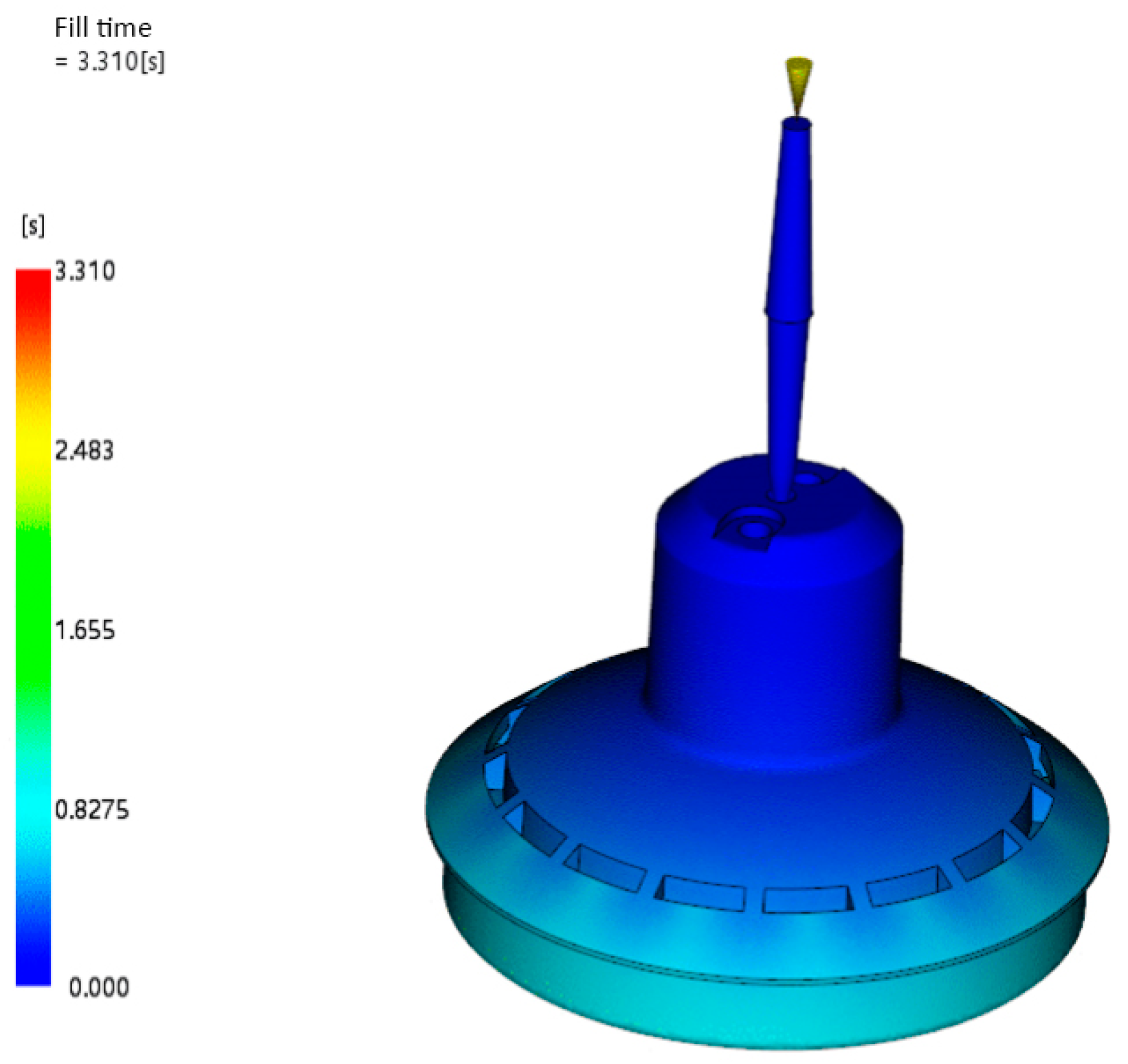
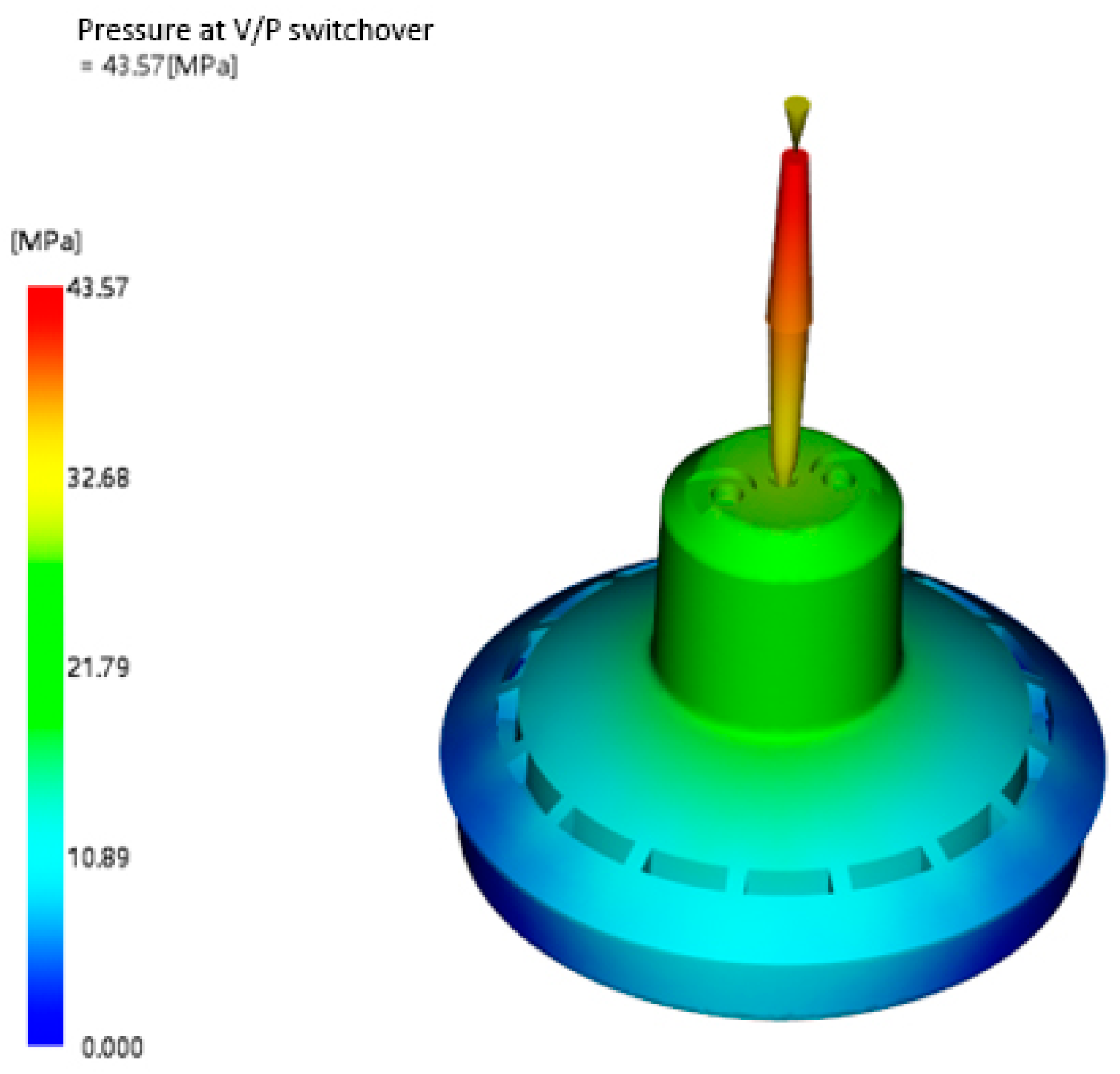
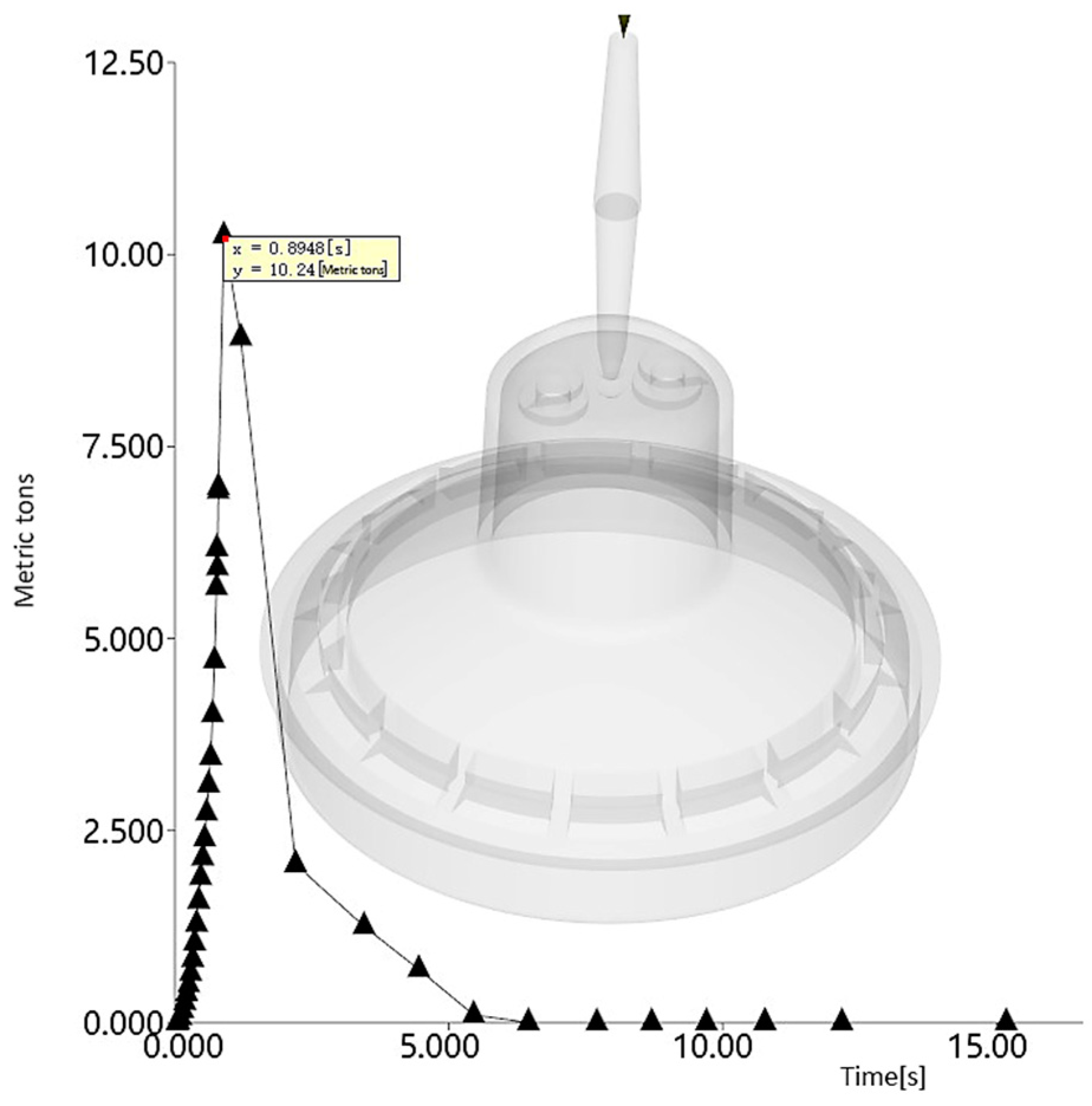
2.3.2. Injection Molding Filling
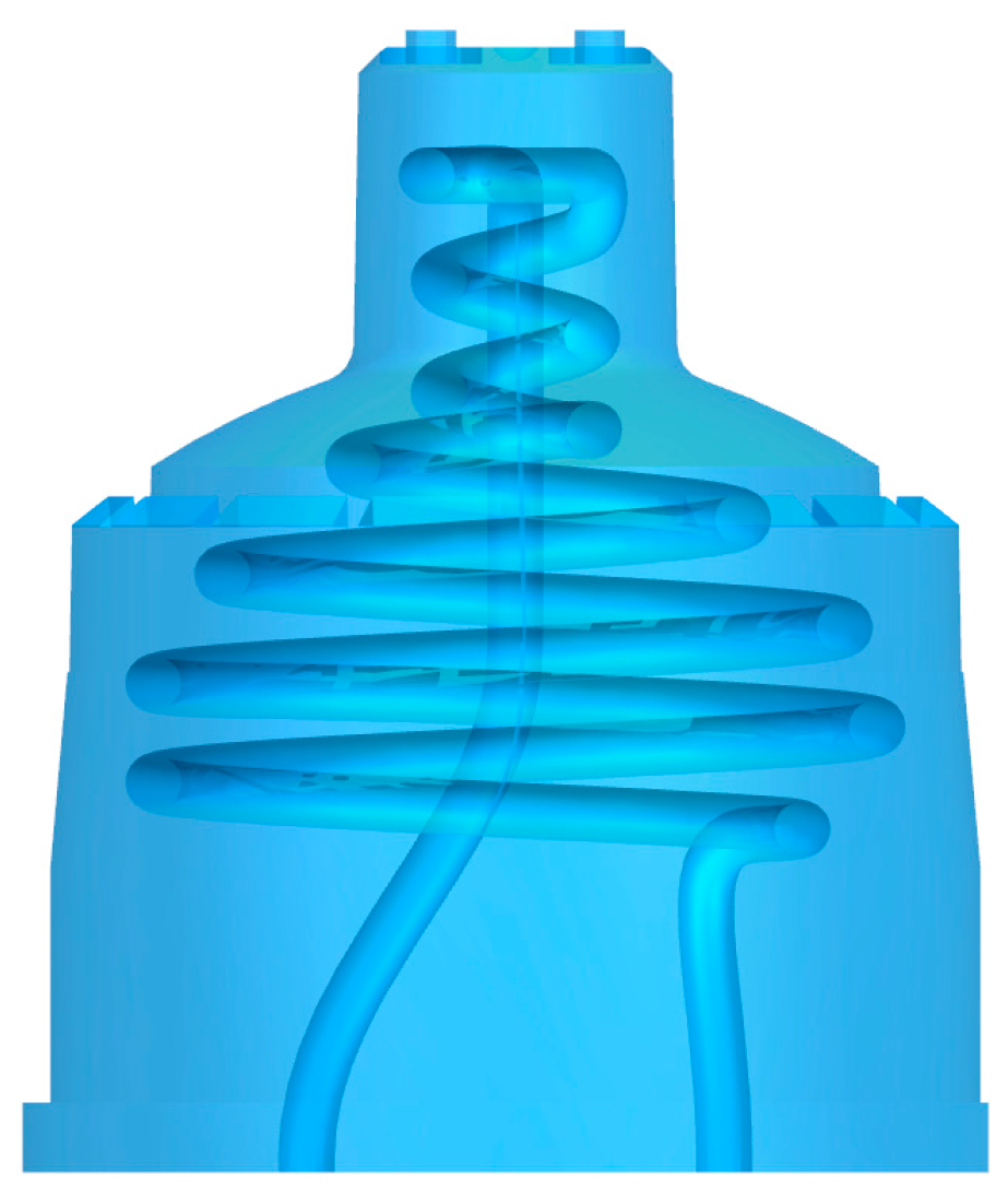
2.3.3. Channel Optimization Design
3. Analysis and Results
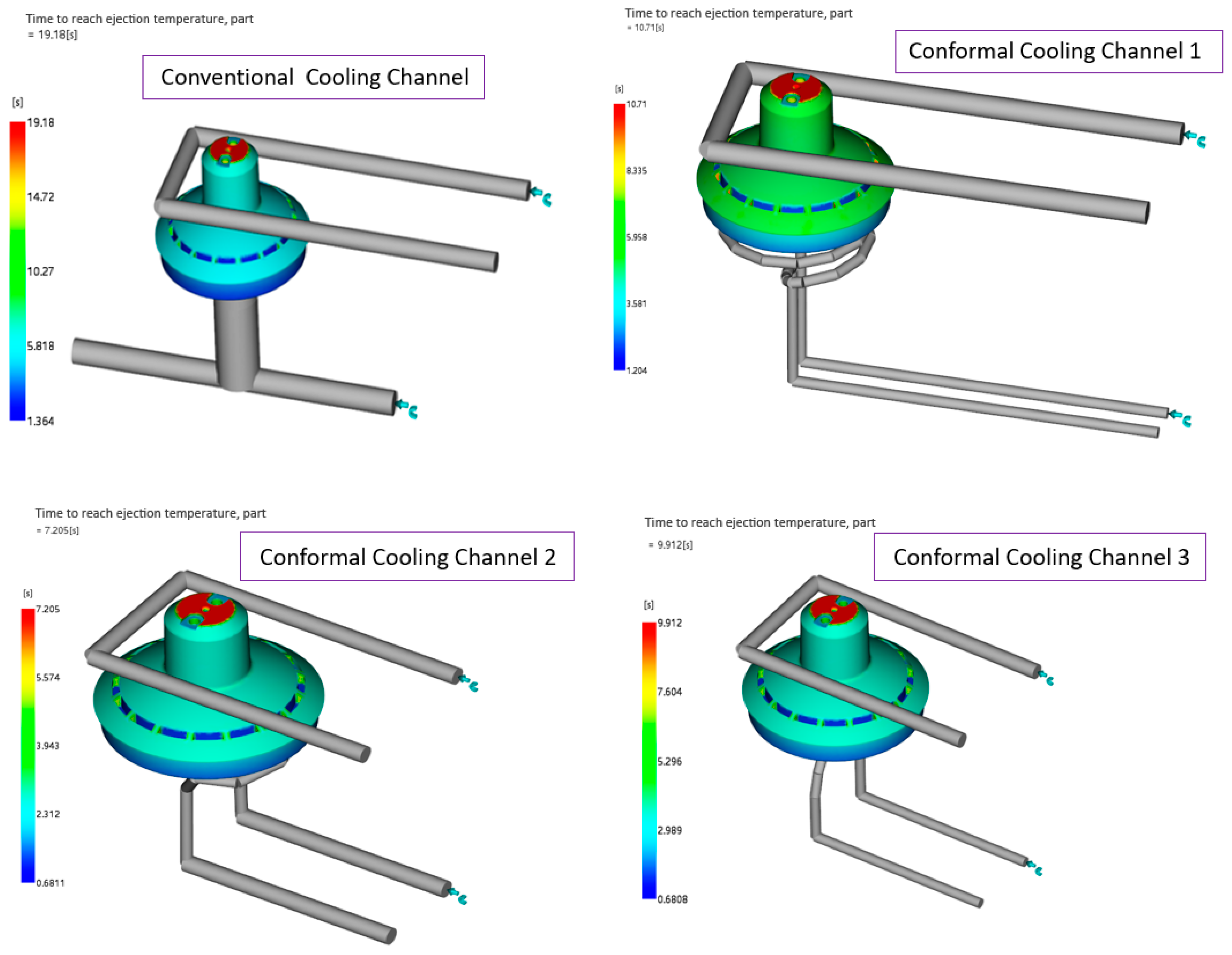
3.1. Cooling Time Analysis
3.2. Test Verification
4. Conclusions
Author Contributions
Funding
Data Availability Statement
Conflicts of Interest
References
- Rosato, D.V.; Rosato, M.G. Injection Molding Handbook; Springer eBooks: Berlin/Heidelberg, Germany, 2000. [Google Scholar] [CrossRef]
- Adam, I.; Du Preez, W.B.; Combrinck, J. Design considerations for additive manufacturing of conformal cooling channels in injection moulding tools. Interim Interdiscip. J. 2016, 15, 35–44. [Google Scholar]
- Dimla, D.E.; Camilotto, M.; Miani, F. Design and optimisation of conformal cooling channels in injection moulding tools. J. Mater. Process. Technol. 2005, 164, 1294–1300. [Google Scholar] [CrossRef]
- Venkatesh, G.; Kumar, Y.R.; Raghavendra, G. Comparison of straight line to conformal cooling channel in injection molding. Mater. Today Proc. 2017, 4, 1167–1173. [Google Scholar] [CrossRef]
- Ma, Y.H. Research on the Optimal Design and Application for the Conformal Cooling Channel of the Injection Mold Based on 3d Printing. Master’s Thesis, Qingdao University of Science & Technology, Qingdao, China, 2020. [Google Scholar]
- Liu, J.; Chen, Q.; Liang, X.; To, A.C. Manufacturing cost constrained topology optimization for additive manufacturing. Front. Mech. Eng. 2019, 14, 213–221. [Google Scholar] [CrossRef]
- Zou, Z.M. Analysis of the influence of mold temperature status on the quality of injection molded products. J. Sanming Univ. 2000, S3, 110–111. [Google Scholar]
- Sun, Y.; Lee, K.; Nee, A. Design and FEM analysis of the milled groove insert method for cooling of plastic injection moulds. Int. J. Adv. Manuf. Technol. 2004, 24, 715–726. [Google Scholar] [CrossRef]
- Dang, X.P.; Park, H. Design of U-shape milled groove conformal cooling channels for plastic injection mold. Int. J. Precis. Eng. Manuf./Int. J. Korean Soc. Precis. Eng. 2011, 12, 73–84. [Google Scholar] [CrossRef]
- Marques, S.; De Souza, A.F.; De Miranda, J.R.; Yadroitsau, I. Design of conformal cooling for plastic injection moulding by heat transfer simulation. Polímeros 2015, 25, 564–574. [Google Scholar] [CrossRef]
- Jahan, S.A.; El-Mounayri, H. Optimal conformal cooling channels in 3D printed dies for plastic injection molding. Procedia Manuf. 2016, 5, 888–900. [Google Scholar] [CrossRef]
- Jahan, S.A.; El-Mounayri, H. A thermomechanical analysis of conformal cooling channels in 3D printed plastic injection molds. Appl. Sci. 2018, 8, 2567. [Google Scholar] [CrossRef]
- Jahan, S.A.; Wu, T.; Zhang, Y.; Zhang, J.; Tovar, A.; El-Mounayri, H. Thermo-mechanical Design Optimization of Conformal Cooling Channels using Design of Experiments Approach. Procedia Manuf. 2017, 10, 898–911. [Google Scholar] [CrossRef]
- Li, Z.; Wang, X.; Gu, J.; Ruan, S.; Shen, C.; Lyu, Y.; Zhao, Y. Topology optimization for the design of conformal cooling system in thin-wall injection molding based on BEM. Int. J. Adv. Manuf. Technol. 2017, 94, 1041–1059. [Google Scholar] [CrossRef]
- Feng, S.; Kamat, A.M.; Pei, Y. Design and fabrication of conformal cooling channels in molds: Review and progress updates. Int. J. Heat Mass Transf. 2021, 171, 121082. [Google Scholar] [CrossRef]
- Arman, S.; Lazoglu, I. A comprehensive review of injection mold cooling by using conformal cooling channels and thermally enhanced molds. Int. J. Adv. Manuf. Technol. 2023, 127, 2035–2106. [Google Scholar] [CrossRef]
- Yuan, A.F. Study on the Design and Application of Conformal Cooling Channel for Injection Mold. Master’s Thesis, China University of Mining & Technology, Jiangsu, China, 2021. [Google Scholar]
- Tang, Z.Y.; Li, D.Q.; Xu, P.X. Plastic Mold Designer’s Guide; National Defense Industry Press: Beijing, China, 1999. [Google Scholar]
- Rao, N.S.; Schumacher, G. Design Formulas for Plastics Engineers; Carl Hanser Verlag GmbH Co. KG: Munich, Germany, 2014. [Google Scholar]
- Ma, Y.H.; Wang, X.X.; Dong, Z.J.; Wang, J.C.; Liu, Q. Research progress in optimization design for conformal cooling channel of injection mold based on 3D printing. China Plast. 2019, 33, 130–137. [Google Scholar]
- Wang, Y.; Lee, C.M. Design and optimization of conformal cooling channels for increasing cooling efficiency in injection molding. Appl. Sci. 2023, 13, 7437. [Google Scholar] [CrossRef]
- Mayer, S. Optimised Mould Temperature Control Procedure Using DMLS; EOS Whitepaper; EOS GmbH Ltd.: Munich, Germany, 2005; pp. 1–10. [Google Scholar]
- Li, H.H. Comparative study on optimizing experimental design methods. Inn. Mong. Sci. Technol. Econ. 2021, 4, 63–65. [Google Scholar]
- Venkatesh, G.; Kumar, Y.R. Thermal analysis for conformal cooling channel. Mater. Today Proc. 2017, 4, 2592–2598. [Google Scholar] [CrossRef]
- ASTM D1238; Standard Test Method for Melt Flow Rates of Thermoplastics by Extrusion Plastometer. ASTM D1238-23a. ASTM International: West Conshohocken, PA, USA, 2023.
- ASTM D638; Standard Test Method for Tensile Properties of Plastics. ASTM D638-22. ASTM International: West Conshohocken, PA, USA, 2022.
- ASTM D790; Standard Test Methods for Flexural Properties of Unreinforced and Reinforced Plastics and Electrical Insulating Materials. ASTM D790-17. ASTM International: West Conshohocken, PA, USA, 2017.
- ASTM D256; Standard Test Methods for Determining the Izod Pendulum Impact Resistance of Plastics. ASTM D256-23e1. ASTM International: West Conshohocken, PA, USA, 2023.
- ASTM D648; Standard Test Method for Deflection Temperature of Plastics Under Flexural Load in the Edgewise Position. ASTM D648-18. ASTM International: West Conshohocken, PA, USA, 2018.
- ASTM D1525; Standard Test Method for Vicat Softening Temperature of Plastics. ASTM D1525-17e1. ASTM International: West Conshohocken, PA, USA, 2017.
- Khan, M.A.; Afaq, S.K.; Khan, N.U.; Ahmad, S. Cycle time reduction in injection molding process by selection of robust cooling channel design. ISRN Mech. Eng. 2014, 2014, 968484. [Google Scholar] [CrossRef]


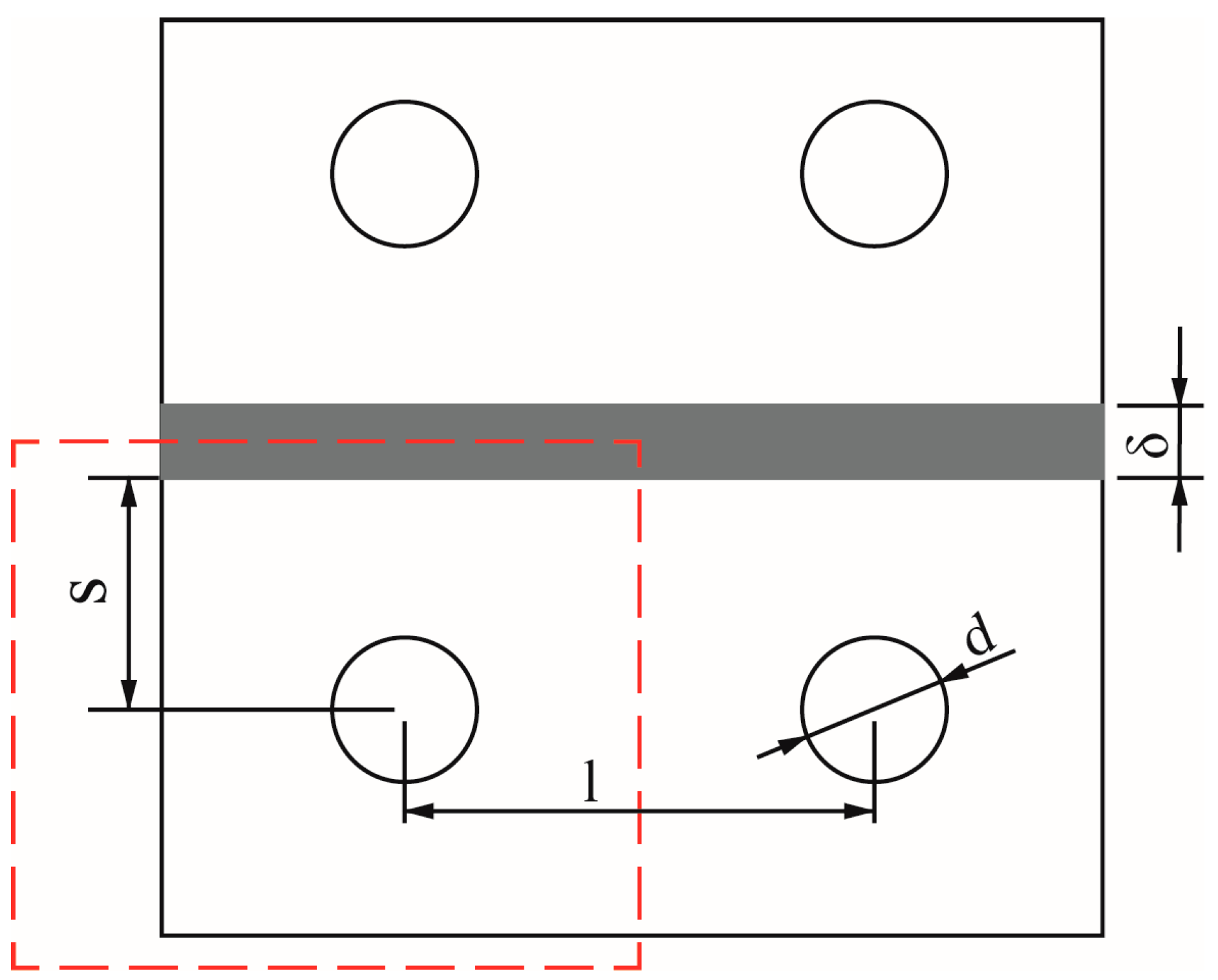
| (mm) | (mm) | (mm) | (mm) |
|---|---|---|---|
| 0–2 | 4–8 | (2–3) d | (1.5–2) d |
| 2–4 | 8–12 | (2–3) d | (1.5–2) d |
| 4–6 | 12–14 | (2–3) d | (1.5–2) d |
| Levels | Factors | ||
|---|---|---|---|
| (mm) | (mm) | (mm) | |
| 1 | 4 | 12 | 8 |
| 2 | 6 | 18 | 12 |
| Test Number | (mm) | (mm) | (mm) |
|---|---|---|---|
| 1 | 4 | 12 | 8 |
| 2 | 4 | 12 | 12 |
| 3 | 4 | 18 | 12 |
| 4 | 4 | 18 | 8 |
| 5 | 6 | 12 | 8 |
| 6 | 6 | 12 | 12 |
| 7 | 6 | 18 | 8 |
| 8 | 6 | 18 | 12 |
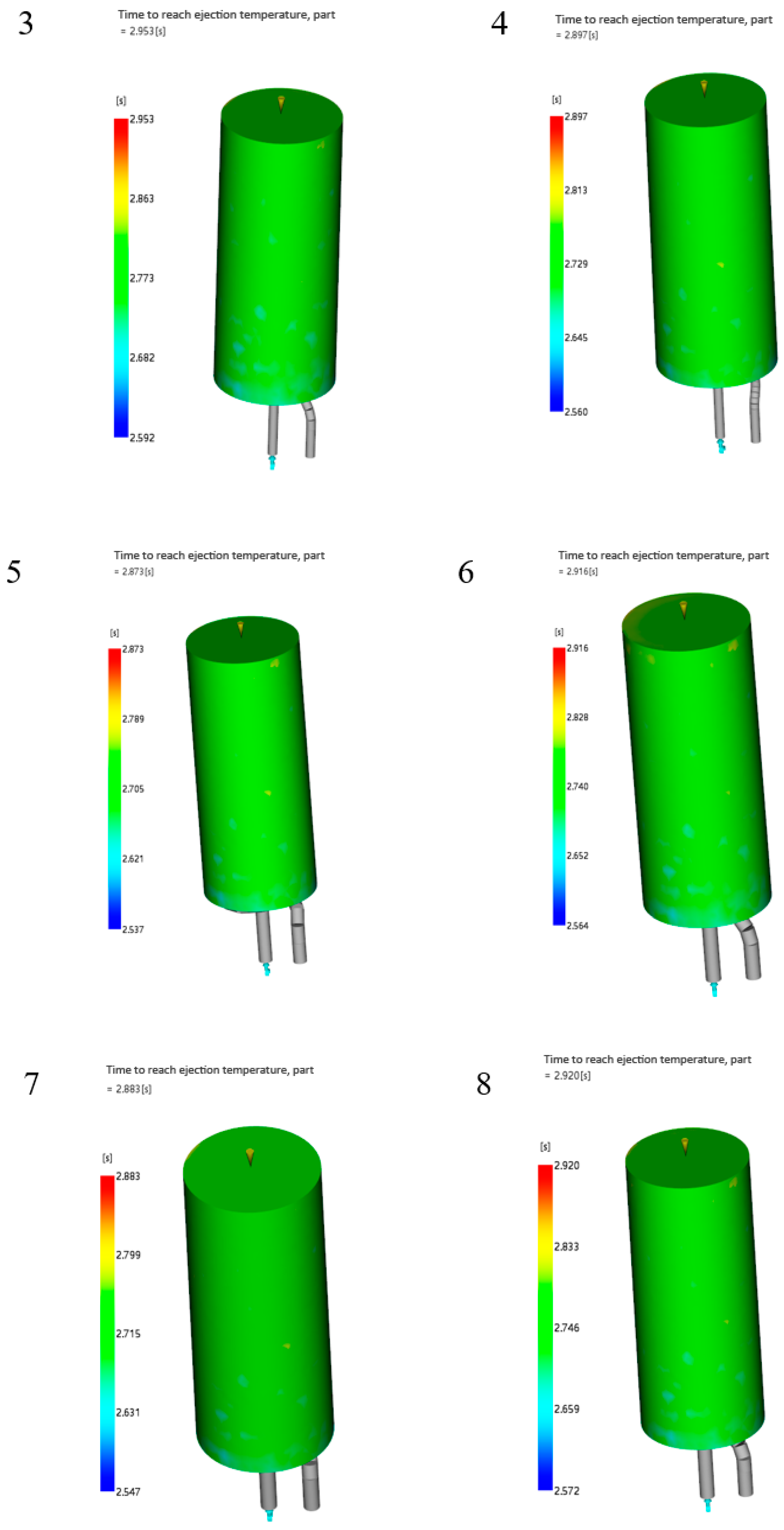
| Test Number | (mm) | (mm) | (mm) | Cooling Time/yt (s) |
|---|---|---|---|---|
| 1 | 4 | 12 | 8 | 2.884 |
| 2 | 4 | 12 | 12 | 2.931 |
| 3 | 4 | 18 | 12 | 2.953 |
| 4 | 4 | 18 | 8 | 2.897 |
| 5 | 6 | 12 | 8 | 2.873 |
| 6 | 6 | 12 | 12 | 2.916 |
| 7 | 6 | 18 | 8 | 2.883 |
| 8 | 6 | 18 | 12 | 2.920 |
| Performance | Test Method | Test Condition | Unit | Parameter |
|---|---|---|---|---|
| Melt flow rate | ASTM D1238 [25] | 220 °C, 10 kg | g/10 min | 22 |
| Tensile strength | ASTM D638 [26] | 3 mm, 6 mm/min | kg/cm2 | 460 |
| Bending strength | ASTM D790 [27] | 6 mm, 2.8 mm/min | kg/cm2 | 790 |
| Impact strength | ASTM D256 [28] | 3 mm, 23 °C | kg-cm/cm | 21 |
| Heat distortion temperature | ASTM D648 [29] | Annea | °C | 95 |
| Vicat softening temperature | ASTM D1525 [30] | 3 mm, 50 °C/h | °C | 105 |
| Process Parameter Items | Unit | Parameter |
|---|---|---|
| Mold surface temperature | °C | 50 |
| Melt temperature | °C | 230 |
| Ejection temperature | °C | 88 |
| Cooling water temperature | °C | 25 |
| Maximum shear stress | MPa | 0.28 |
| Maximum shear speed | 1/s | 12,000 |
| Compress time | s | 10 |
| Holding pressure | MPa | 70 |
| Nozzle pressure maximum | MPa | 43.57 |
| Comparative Items | Cooling Time |
|---|---|
| Conventional cooling channel | 19.18 s |
| Conformal cooling channel 1 | 10.71 s |
| Conformal cooling channel 2 | 7.205 s |
| Conformal cooling channel 3 | 9.912 s |
Disclaimer/Publisher’s Note: The statements, opinions and data contained in all publications are solely those of the individual author(s) and contributor(s) and not of MDPI and/or the editor(s). MDPI and/or the editor(s) disclaim responsibility for any injury to people or property resulting from any ideas, methods, instructions or products referred to in the content. |
© 2024 by the authors. Licensee MDPI, Basel, Switzerland. This article is an open access article distributed under the terms and conditions of the Creative Commons Attribution (CC BY) license (https://creativecommons.org/licenses/by/4.0/).
Share and Cite
Li, J.; Ong, Y.C.; Wan Muhamad, W.M. Optimization Design of Injection Mold Conformal Cooling Channel for Improving Cooling Rate. Processes 2024, 12, 1232. https://doi.org/10.3390/pr12061232
Li J, Ong YC, Wan Muhamad WM. Optimization Design of Injection Mold Conformal Cooling Channel for Improving Cooling Rate. Processes. 2024; 12(6):1232. https://doi.org/10.3390/pr12061232
Chicago/Turabian StyleLi, Jinyi, Yung Chieh Ong, and Wan Mansor Wan Muhamad. 2024. "Optimization Design of Injection Mold Conformal Cooling Channel for Improving Cooling Rate" Processes 12, no. 6: 1232. https://doi.org/10.3390/pr12061232