Article

Study on Multi-Scale Cloud Growth Characteristics of Frustoconical Dispersal Devices

1
State Key Laboratory of Explosion Science and Technology, Beijing Institute of Technology, Beijing 100811, China
2
School of Mechanical and Electrical Engineering, North University of China, Taiyuan 030051, China
*
Author to whom correspondence should be addressed.
Processes 2024, 12(7), 1316; https://doi.org/10.3390/pr12071316
Submission received: 28 April 2024 / Revised: 21 June 2024 / Accepted: 21 June 2024 / Published: 25 June 2024

Abstract

:
This study aims to understand cloud growth behavior and enhance cloud safety and reliability by investigating the design of cloud dispersal devices. Based on the experimental results and simulation results, this study analyzes the dispersion characteristics of cloud materials within a frustoconical device with a semi-cone angle ranging from 0° to 10° across multiple scales. The collision aggregation model for cloud particles and the multi-scale coupling mechanism for cloud growth are established. The research shows that the semi-cone angle of the device extends the effective cloud growth duration and enlarges the cloud macroscopic size. At the mesoscopic scale, vortex phenomena are observed, causing particles to converge within the cloud, resulting in collisions and aggregation. The vortices enhance the continuity of the cloud concentration. The magnitude of these vortices demonstrates a positive correlation with the magnitude of the semi-cone angle of the dispersal device. For a macroscopically stable cloud, the high-concentration area within the cloud moves outward radially with an increase in the semi-cone angle. This study provides a theoretical foundation for cloud morphology control technology, contributing to enhancing the safety and reliability of cloud systems.

1. Introduction

In a cloud dispersal device, the cloud material is concentrated in a narrow space. Under the effect of the driving load, the cloud material disperses in all directions, and finally, the cloud is formed. In recent years, because of the widespread presence of clouds in firefighting as well as in industry, research on techniques for controlling cloud morphology has attracted much attention in the corresponding fields. In the field of firefighting, the fire-extinguishing agents in the fire-extinguishing bomb are formed into a cloud, which improves the efficiency of remote firefighting and wide-area firefighting [1]. However, extinguishing agents have complex non-constant and unpredictable flow characteristics during cloud formation, which limit the terminal extinguishing efficiency of the cloud. The technology for cloud morphology control aids in controlling the dispersal of fire-extinguishing agents driven by loads, and it enables the real-time and efficient formation of appropriately sized and concentrated fire-extinguishing clouds to cover fire source locations, rapidly extinguishing fires and preventing explosions. In industrial generations, combustible industrial dusts (such as oil, natural gas, coal, flour, etc.) are easily formed into combustible clouds, and there is a risk of dust explosions [2,3]. The technology for cloud morphology control aids in controlling the size and concentration distribution of combustible industrial dust cloud, thereby preventing dust explosions and reducing casualties. Therefore, it is important to study the dispersal mechanisms of cloud, master cloud morphology control technology, and then control the cloud size and concentration distribution, which are significant in optimizing cloud and cloud safety and reliability in the firefighting and industrial fields.
To master the technology for cloud morphology control, many scholars have explored the influence of the structure of the cloud dispersal device on cloud dispersal, founded on the idea that the shell structure of the device directly influences the size of the cloud [4,5,6]. Currently, most cloud dispersal devices adopt cylindrical shell structures [7], and the actual cloud dispersal is a dynamic process, resulting in an umbrella-shaped cloud. However, the cloud size resulting from dynamic dispersal is smaller than that from static dispersal [8], resulting in the concentrated distribution of the cloud, which is not only detrimental to expanding the area of fire extinguishing but also increase the risk of dust explosions. Introducing a frustoconical cloud dispersal device can increase the cloud size [9], compensating for the drawbacks of dynamic cloud dispersal. Furthermore, by controlling the shape of the frustoconical cloud dispersal device shell, altering the velocity direction of cloud dispersal [10], and coupling it with the dynamic dispersal velocity, one can further increase the cloud size under dynamic dispersal conditions, enhancing the cloud size effect. Therefore, studying the effect of the semi-cone angle, which refers to the angle between the generatrix and the axis of a frustoconical dispersal device, on the morphological characteristics of multiphase cloud aids in better comprehending how shell design parameters influence the control strategies for cloud dispersal, thereby optimizing the extinguishing efficiency of the extinguishing agent cloud as well as the safety of the industrial dust. This research holds significant value in engineering and safety practices.
For frustoconical dispersal systems, the cloud growth process involves the near-field dispersal dominated by the driving load and the far-field dispersal dominated by the aerodynamic resistance [11,12]. The cloud growth process can be described by the central propulsion model [13], shell rupture model [14], fuel injection model [15], and droplet breakup mechanisms [16], etc. Ripley and Zhang [17] analyzed the unstable mechanisms of jet formation, growth, and disappearance during fuel cloud dispersal. Li et al. [18] studied the influence of the tension and shear forces generated by reflected waves on the cloud dispersal process. Ye et al. [19], through numerical simulations, obtained the concentration distribution of gas–liquid phase fuel under unconstrained conditions, demonstrating the dynamic instantaneous isothermal field of the entire fuel cloud area during the dispersal process. Zhang [20] proposed the physical mechanism of a dual jet structure, suggesting the formation of unstable jets at the boundary between the cloud and the air. Despite previous research exploring cloud dispersal mechanisms, the current research results concerning the cloud dispersal mechanism are based on cylindrical cloud dispersal devices and do not address the dependence of the cloud growth mechanism on the semi-cone angle of the device [21,22]. At the same time, the mesoscopic growth mechanism of clouds is still unclear, and the existing studies lack the exploration of the mesoscopic flow characteristics of clouds. None of these are sufficient to make accurate predictions of the size and concentration during cloud growth.
Given the context, this study adopts the self-compiled CFD-DPM method to numerically simulate the cloud dispersal process of a frustoconical device with a 0° to 10° semi-cone angle. This study also investigates the cloud dispersal characteristics based on the numerical simulation results at multiple scales. In detail, this study is first carried out from a macroscopic perspective to investigate the size effect of the device’s semi-cone angle on the growth of the cloud. Subsequently, mesoscopic analysis is introduced to explain the macroscopic growth mechanism of the cloud, which in turn reveals the multiscale coupling mechanism for the growth of the cloud formed by the frustoconical dispersal device. Meanwhile, in the multi-scale study process, this study elucidates the oblique pressure effect and vortex effect of the device’s semi-cone angle on the cloud growth. It describes the particle collision phenomenon induced by the vortex effect by proposing the cloud particle collision aggregation model, which makes the prediction of the cloud concentration more accurate. This study helps to further master the technology for cloud morphology control, and it will provide a reference for the design of fire-extinguishing bombs as well as the optimization of industrial dust environments.

2. Numerical Simulation Method

The aim is to explore the multi-phase cloud dispersal characteristics of the frustoconical cloud dispersal device; hence, the cloud dispersal device shown in Figure 1 is investigated. The cloud dispersal device consists of the shell, the cloud material, and the central propulsion system. The device is the shape of a conical frustum, where β0 represents the angle between the device shell generatrix and the axis, referred to as the semi-cone angle. A comparative study is conducted within the range of 0° to 10°.
In the process of a cloud-governing device, the center propulsion device applies a load to the cloud material, which expands and breaks the shell and disperses it into the air. Based on the cloud dispersal-governing equations, this study adopts self-compiled CFD-DPM numerical simulation to calculate the cloud characteristics of different semi-cone angle devices to lay a numerical foundation for investigating the influence of the device’s semi-cone angle on the multi-phase cloud dispersal characteristics.

2.1. Governing Equation

The process of cloud dispersal can be divided into the initial breakup of cloud materials driven by the driving load and the subsequent dispersal of cloud particles in the propagation medium.

2.1.1. The Initial Breakup of Cloud Materials

The initial breakup process of cloud materials under the driving force includes shell rupture and material ring primary breakup. The cloudy material in the initial breakup stage can be regarded as solid due to its own condensed phase characteristics, so the initial breakup of the cloudy materials belongs to the typical problems in impact dynamics and material rupture. Traditional mesh-based finite volume methods can be utilized to quantitatively describe and predict the rupture process of the cloud material [23].
Considering that the cloud material has a slight density change in the material density during the initial rupture process and always remains in the compression state, the polynomial equation of state is used to describe the cloud material:
P = B 1 η + B 2 η 2 + B 0 ρ s E M ,
where P is the pressure applied, EM is the increase in internal energy per unit mass, η is the ratio of the change in density to the initial density, and ρs is the density of the cloud material when it is a condensed phase. B1, B2, and B0 are constants that are directly related to the properties of the cloud material. Considering the condensed phase properties of the cloud material, when B1 is taken as 2.2 GPa, B2 is taken as 0 GPa and B0 is 0.28, which matches the actual situation.
The shell is described using the shock state equation and the Johnson–Cook constitutive model:
U s = C 0 + B 3 U p ,
where Us is the driven velocity; Up is the material mass velocity; and C0 is the bulk sound velocity. B3 is the velocity coefficient, which is taken as 1.338.
σ s = A 1 + A 2 s p n 1 + A 3 ln s ˙ p * 1 T H m ,
where sp is the plastic strain of the material, s ˙ p * is the plastic strain rate of the material, and TH is the environmental temperature. A1 is the yield stress, A2 is the strain-hardening constant, A3 is the strain rate sensitivity parameter, n is the strain-hardening index, and m is the temperature softening index. Under a driving load, the temperature softening index m is not important because the temperature rise due to the heat of deformation is small, and the stress reduction is very limited when the material appears to be strengthened and then close to failure. Therefore, the relevant parameters are corrected as follows: A1 = 335 MPa, A2 = 219 MPa, A3 = 0.014, n = 0.26, m = 0.

2.1.2. The Dispersal of Cloud Particles

In the dispersal stage of the cloud particles, the cloud particles can be regarded as a discrete phase; then, the process of cloud dispersal can be considered as the movement of the discrete phase through the continuous phase air [15]. Therefore, for the cloud dispersal process, its foundational logic lies in the description of the Navier–Stokes equations detailing the movement details of the multiphase flow, as induced by the particles in each phase particle and by all the internal fluids.
The continuity equation can be expressed as:
ρ t + ρ u = S m ,
where ρ is the fluid density, u is the fluid velocity, and Sm comes from the mass flux of the particle phase, which is taken as 0.
The momentum conservation equation (Navier–Stokes equation) can be expressed as:
t ρ u + ρ u i u j = p + τ i j + ρ g + F E ,
where i, j are two mutually perpendicular directions in a 2-dimensional plane, p is the static pressure, τij is the stress tensor, and ρg and FE are the gravitational volumetric and external volumetric forces, respectively.
The energy conservation equation can be expressed as:
t k ρ k E k + k u k ρ k E k + p = κ e f f T k h k J k + u τ i j e f f + S h ,
E k = h k p ρ k + u k 2 2 , κ e f f = 0.01006 + 5.413 × 10 5 T + c p , k μ t p r t ,
where k represents the phases in the problem; T is the fluid temperature; prt is the turbulent Prandtl number, which is taken as 0.85 [24]; h is the sensible enthalpy of the compressible gas; J is the diffusive flux; cp is the specific heat capacity of the substance; and Sh contains the chemical reaction energy source term in this study, ignoring the heat of the chemical reaction, which is taken as 0.
The turbulent flow of the fluid is obtained by solving the conservation equations with respect to the turbulent kinetic energy k and the dissipation rate ε using the standard k-ε method:
p k t + p k u i x i = x j μ + μ t σ k k x j + G k + G b ρ ε Y M + S k p ε t + p ε u i x i = x j μ + μ t σ k ε x j + C 1 ε ε k G k + C 3 ε G b C 2 ε ρ ε 2 k + S ε ,
where μt is the turbulent viscosity, μt = ρCμk2/ε; and Gk denotes the generation term of the turbulent kinetic energy k caused by the mean velocity gradient. Gb is the generation term of the turbulent kinetic energy k caused by the buoyancy force. C1ε, C2ε, Cμ, σk, and σε are the model constants, taking the values of 1.44, 1.92, 0.09, 1.0, and 1.3 [25], respectively. It is stated in the literature [25] that these default values are considered appropriate as they are derived from experiments on elementary turbulence, including frequent shear flows (e.g., boundary layer, mixed layer, and jet) and attenuated anisotropic mesh turbulence. They have been found to be quite effective under different flow conditions and can show good predictive power. C3ε is the coefficient associated with the buoyancy force in the computation of the flow of pressurized fluid, taking the value of 1 and 0 when the main stream direction is perpendicular and parallel to the gravity direction, respectively. In this study, fuel diffusion is considered an incompressible process, and since YM is the fluctuation generated by the transition diffusion in the compressible turbulence, it is taken as YM = 0. Sk and Sε are user-defined to be taken as 0.
The species equation represents the change in mass of each cloud material component within the system. The species transport equation is employed to describe the evaporation of the liquid phase materials:
t ρ Y j + ρ u Y j = J j + S j ,
where Yj is the mass fraction of substance j′. Sj is the additional velocity of substance j′ resulting from the evaporation of the liquid phase cloud particles.
During cloud dispersal, solid–liquid phase particles account for less than 12% of the continuous phase content relative to the surrounding air. Consequently, incorporating a discrete phase model to compute the trajectories of cloud particles, the force balance equation governing particle interactions is formulated in Cartesian coordinates as follows:
t u p = 18 C D ρ v 24 ρ p d p u v u p 2 + g x ρ p ρ p ρ v + 1 2 ρ d ρ p d p u v u p ,
where ρv is the gas phase density, uv is the gas phase velocity, up is the particle velocity, ρp is the particle density, dp is the particle diameter, and CD is the drag force coefficient.
The secondary breakup of droplets in clouds adopts the Reitz–Diwakar breakup model. The following formula is used, see Equation (11), while Equation (12) is the wavelength of the most unstable wave for a given flow condition Λ and the corresponding maximum growth rate Ω:
Λ r p = 9.02 1 + 0.45 O h 0.5 1 + 0.4 T a 0.7 1 + 0.87 W e 2 1.67 0.6 ,
Ω ρ 1 r p 3 σ = 0.34 + 0.38 W e 2 1.5 1 + O h 1 + 1.4 T a 0.6 ,
where rp is the radius of the droplet group circular jet, σ is the surface tension, Oh is Ohnesorge number, and Ta is the Taylor number.
In the Reitz–Diwakar breakup model, the breakup of droplet clusters results in the formation of smaller liquid droplets, with a radius rp calculated proportionally based on assuming the droplet radius r at the time of breakup relates to the wavelength of the rapidly growing surface waves, as given by Equation (11). The radius of the parent droplet changes at a rate of:
d r p d t = r p B 5 Λ Λ Ω 3.726 B 6 r p , r r p ,
where B5 and B6 are model constants. After repeated trial calculations, when B5 is 0.61 and B6 is 60, the calculation results match the actual.
The droplet evaporation adopts a convection diffusion model, simultaneously considering evaporation under the influence of both convection and diffusion.

2.2. Geometry and Parameters

Based on the governing equations, the dispersal process of the cloud is computed. As shown in Figure 2, the computational geometric model comprises the cloud dispersal device and air. The outlet boundary is the pressure outlet, and the outlet pressure is atmospheric. The initial pressure Pd is applied vertically to the fuel by the center propulsion system to drive the fuel in motion, with a pressure action time of 6 ms. The drive pressure Pd conforms to the function [26], whose validity has been demonstrated for similar problems:
P d = exp 13.88 + 2330.04 t 388339.78 t 2 ,
where the unit of Pd is MPa, while the unit of t is ms.
In Figure 1, the device is the shape of a conical frustum, with the smaller end facing the ground. A total of 13 kg of cloud material is filled into the device. R1 and R2 are the lower and upper base radii of the device shell, respectively. They are determined by the device height and the semi-cone angle β0, satisfying the relationship:
R 1 + R 2 = 200 R 1 = R 1 + R 2 2 2 30 tan β 0 2 12 ,
The cloud material consists of a solid–liquid phase fuel with a solid–liquid ratio of 2:3. The liquid phase fuel has a boiling point set at 307 K and an evaporation latent heat of 431.3 kJ/kg. The other calculated parameters are shown in Table 1.

2.3. Mesh Information

Considering that the model in Figure 2 is axisymmetric, the computational domain can be simplified to a two-dimensional model. For the mesh size, the optimal mesh should ensure that the mesh size is larger than the largest particle size in the area, and researchers [27] have shown that the cloud particles are less than 1 mm in size. Therefore, a mesh size of 3 mm is selected. In order to ensure the accuracy and reliability of the numerical simulation, we adopt a strict convergence criterion. We take the residuals as the main convergence index and require the residuals of each equation to be reduced to less than three orders of magnitude of the initial residuals. For the turbulent kinetic energy and turbulent dissipation rate, we require the residuals to fall below 10−4. The convergence criterion for the energy residual values is below 10−6. During the iterative operation of the equations, to ensure the convergence of the computational solution at each time step, 0.1 ms is selected as the time step based on the mesh size mentioned above [28]. The convergence of the numerical solution is indirectly confirmed by the reliability verification in Section 3.1.2.
To ensure the mesh quality requirements, this paper starts the study with the 0° semi-cone angle case. Based on the workstation (AMD EPYC 7R32 CPU @ 3.3GHz, 96 cores), the divergent mesh and uniform mesh in Table 2 are compared and studied, and the results are shown in Figure 3. The computational error of both is less than 5%, which confirms the independence of the mesh.
When the cloud size from the calculation tends to stabilize, the calculation is stopped. Based on the mesh sensitivity consideration, the time required for the divergent mesh (153 h) is less than that for the uniform mesh (179 h). Therefore, the divergent mesh is used for the computational mode. The condition for a 0° semi-cone angle is illustrated in Figure 4.

3. Results and Discussion

In this section, based on the calculation results for the case of a cone angle 0~10° in Section 2, the macroscopic and mesoscopic multi-scale study aims to explore the mechanism by which the semi-cone angle of the frustoconical device influences the cloud dispersal process.

3.1. Macroscopic Characteristics of Cloud

The macroscopic characteristics of the cloud formed by each semi-cone angle device are analyzed. This is to grasp the overall characteristics of multiphase cloud. Moreover, it can provide an initial description and quantitative understanding of the impact of the frustoconical cloud dispersal device on the cloud dispersal characteristics. Specifically, this section conducts comparative studies on the cloud size growth effects with different semi-cone angles of the cloud dispersal device. It aims to comprehend the influence of the device’s semi-cone angles on the spatial and temporal movement patterns of cloud and incorporates experimental results for verification.

3.1.1. Cloud Size

In the initial stages of cloud dispersal, the central propulsion system drives the rupture of the device shell. It causes the fuel to disperse into the surrounding air medium. The semi-cone angle of the dispersal device causes the initial dispersal velocity of the cloud along the perpendicular direction of the device shell, as shown in Figure 5. The mass of the fuel is the same in the cross-section of the midpoint of the axis of each semi-cone angle device, which is why the central propulsion effect remains consistent. Therefore, at the reference line indicated by the arrows in Figure 5, the initial dispersal velocity of the cross-section at the center of the axis of each semi-cone angle device is basically the same, and the direction is the same as that of the semi-cone angle. However, in the remaining cross-sections of the device, the same propulsion effect and the uneven distribution of cloud material along the axis cause the velocity to decrease gradually from the smaller to the larger end of the device. Furthermore, as the semi-cone angle of the device increases, the initial dispersal velocity at the smaller end tends to be higher, while decreasing toward the larger end. During the process of the fuel escaping the constraints of the device shell, the fuel undergoes deformation. This results in a deviation of ±1.5° in the fuel initial velocity direction. Moreover, as the fuel approaches the end face of the device along the axis, the direction angle of the velocity increases. Refer to Figure 5 for an illustration. The effect produced by the semi-cone angle on the velocity of the cloud material is known as the oblique pressure effect.
From the oblique pressure effect, the radial dispersal velocity vr of the cloud formed by each frustoconical device satisfies:
v r = v 0 cos β 1 = k β 0 v 0 cos β 0 v 0 cos β 0 ,
where, kβ0 is a corrective term for the variation in the cloud velocity caused by the expansion effect of the shell. Combined with the velocity direction angle β1, it can be found that the value of kβ0 ranges from 0.9997 to 1.0005. Since the difference between the correction term kβ0 and 1 is very small, the change in cloud velocity caused by the shell expansion effect can be neglected, and at this time, the radial velocity of the cloud is only related to the β0. The axial velocity of the cloud represents the axial component of the dispersal velocity.
Figure 6 and Figure 7 illustrate the macroscopic growth process of the cloud. The size of the cloud increases over time. Based on the velocity curve, the cloud growth process is divided into the near-field [11] and far-field [12] stages. Moreover, when the growth rate of the cloud size compared to the previous moment is less than 2%, it is considered that the macroscopic size of the cloud ceases to grow, stabilizing its appearance. At 70 ms, the cloud reaches a stable appearance. Based on Equation (15), it can be seen that the oblique pressure effect deviates from the direction of the velocity, which leads to the development of the cloud shape from flattened to umbrella-like with the increase in the semi-cone angle, which can be shown by referring to the dynamical distribution of cloud particles in Section 3.2.1.
The time reference lines shown in Figure 6 delineate the radial growth process of the cloud in the near and far fields. During the period from 0 to 4 ms, the shell of the device ruptures, and the fuel is ejected. The system’s driving force acts as the primary propulsion for the cloud dispersal, causing cloud initiation to accelerate radially, which signifies the near-field growth stage. Due to the identical central propulsion systems, the cloud near-field growth-phase durations for each device remain consistent regardless of the device’s semi-cone angle. Figure 6 shows that the radial growth velocity of the cloud decreases with an increase in the semi-cone angle of the device during the near-field stage. After 4 ms, the central driving effect diminishes, and aerodynamic resistance becomes the dominant force, which leads the cloud to decelerate and transition into the far-field growth stage. The duration of the decelerated growth in the cloud is positively correlated with the semi-cone angle of the device. At 70 ms, compared to the cloud formation created by the 0° semi-cone angle device, the diameter of the cloud created by the 5° semi-cone angle device increased by 3.97%, and the diameter of the cloud formed by the 10° frustum cone angle device increased by 7.55%. Consequently, the radius of the formation of the cloud does not increase with the semi-cone angle of the device, contrary to the relationship between the semi-cone angle and the growth velocity of the near-field phase. In contrast, with an increase in the semi-cone angle of the device, the far-field growth phase of the cloud persists for longer, extending the radial growth phase, resulting in the formation of clouds with a larger radius.
The time reference lines shown in Figure 7 delineate the axial growth process of the cloud in the near and far fields. According to the distribution of the fuel dispersal velocity shown in Figure 5, the direction of the initial fuel dispersal velocity is along the normal direction of the device generatrix. As per Equation (15), with an increase in the semi-cone angle of the device, the axial component of the cloud dispersal velocity increases, leading to a higher peak value in terms of the axial growth velocity. Moreover, with an expanding semi-cone angle, the duration of the axial growth phase of the cloud in the far field extends, resulting in an enlargement of the axial size of the cloud. At 70 ms, compared to the cloud formed by a 0° semi-cone angle device, the height of the cloud generated by a 5° semi-cone angle device has increased by 8.12%. Similarly, the cloud formed by the 10° semi-cone angle device shows a 20.81% increase in height compared to the 0° semi-cone angle device.
It should be noted that the growth time-course curve in Figure 6 and Figure 7 show undulation and are concentrated in the far-field growth phase of the cloud. The same growth undulation phenomenon was observed in the experimental study of 80 kg and 300 kg of liquid–solid fuel casting by Xu et al. [29]. Combined with the turbulence characteristics during the cloud growth shown in Figure 8 [30], it can be seen that cloud growth induces a rapid increase in the turbulence intensity at the cloud size location, followed by a slow decrease. Due to the continuous existence of turbulence intensity, the turbulent mixing inside the cloud will lead to an inconsistent mixing speed between different regions, which in turn affects the overall growth rate and size and shows undulation in the growth curve.
In summary, both the axial and radial dispersal of the fuel cloud are influenced by the device’s semi-cone angle, yet the growth trends of the fuel cloud in both the axial and radial directions are similar. The height of the cloud formed by various semi-cone angle devices stabilizes after 38.43 ms. The boundary for the duration of the axial far-field growth of the cloud is smaller than that of the radial far-field growth. Therefore, the moment at which the radial size of the cloud stabilizes can be considered the shaping time for the overall size of the fuel cloud. The periods of radial near-field and far-field growth are referred to as the effective growth time for the cloud size. It is observed that the semi-cone angle of the dispersal device increases the cloud’s effective growth time. Moreover, a larger semi-cone angle of the device effectively extends the cloud’s effective growth time, leading to the formation of a larger-sized fuel cloud.

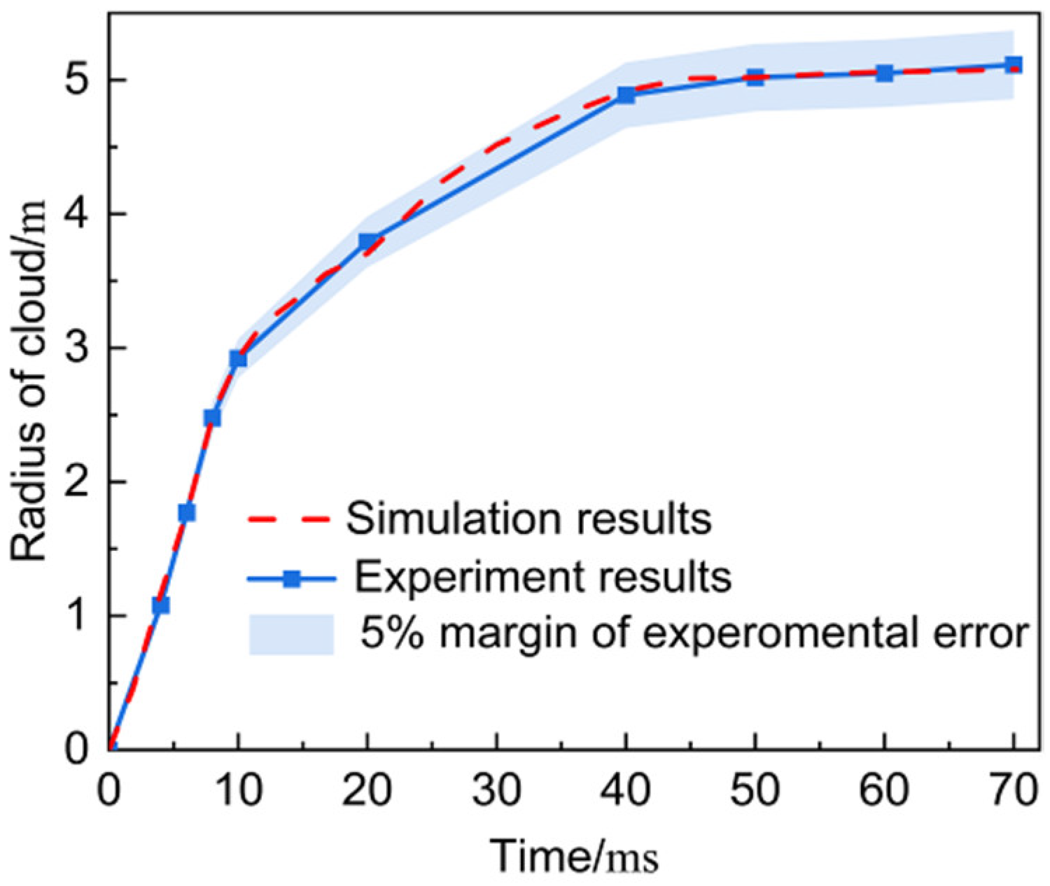
3.1.2. Reliability Verification

To verify the accuracy of the computed analysis, the experimental results for the 0° semi-cone angle cloud dispersal device are introduced to verify the macroscopic size of the cloud. In the experiment, a high-speed motion analysis system is used to observe the cloud dispersion process in real time. In order to prevent dust explosions, the horizontal distance between the high-speed camera system and the cloud dispersal device is 100 m. The high-speed camera system has a shooting frequency of 2000 fps and a photo resolution ratio of 1280 × 800, which can be used to calculate and analyze the macroscopic size of the cloud based on the experimental observation photos.
The growth process of the cloud with the 0° semi-cone angle device is illustrated in Figure 9 and Figure 10, showing that the shape of the simulated cloud closely is consistent with the experimental observation.
Figure 11 and Figure 12 represent the verification results. The solid lines in the figures depict the temporal curve of 13 kg fuel dispersal observed in real time using the high-speed analysis system, with the shaded regions denoting the credible error margins of 5% and 3% around the experimental results. The dashed lines in the figures represent the simulation results.
Figure 11 and Figure 12 illustrate that the size of the fuel cloud undergoes phases of accelerated growth followed by decelerated growth with the time progression. Beyond 40 ms, the growth gradient of the cloud size diminishes over time, consistently remaining below 2%, indicating that the cloud morphology is stable. The numerical simulation results depicted in the figures align with the growth trends observed in the experiments. Additionally, the maximum error in the cloud radius is 4.76%, and for the cloud height, it is 2.63%. The simulation results consistently fall within the credible error margins, verifying the reliability of the simulation results.

3.2. Mesoscopic Characteristics of Cloud

To explore the mechanisms behind the macroscopic growth of cloud, this study delves into the mesoscopic characteristics of cloud particles. By studying the particle trajectories, dispersal processes, and inter-particle interactions, it aims to reveal the mesoscale intricacies of cloud growth. This involves quantitatively assessing the particle size distributions and concentration variations within cloud, comprehensively grasping the nuanced features of cloud during multiphase fuel dispersal and understanding the influence mechanisms of the semi-cone angle on cloud dispersal.

3.2.1. Cloud Particle Size Distribution

Studying the particle size distribution of clouds formed by the 0°, 5°, and 10° semi-cone angle devices aims to explore the size variations, motion behaviors, and interactions among the particles during the dispersal process. Figure 13 illustrates the particle size distribution at different times for clouds formed by 0°, 5°, and 10° semi-cone angle devices.
Within the first 4 milliseconds of cloud growth depicted in Figure 13, the fuel undergoes near-field movement. During this period, the fuel is driven by the strong driving forces, rapidly disintegrating into particles smaller than 1000 μm in diameter. The breakup of the liquid-phase fuel during the dispersal process is primarily influenced by aerodynamic stripping and evaporative atomization effects. The rate of change in the droplet size satisfies the following equation [31]:
δ = dV r L 3 dt = 9 k V N u T A T F π r F ρ F L + 3 ρ A μ A ρ F μ F 1 / 6 μ F ρ F 1 / 2 v A v F 1 / 2 r F 3 / 2 ,
where the subscript “A” represents the physical quantity corresponding to air; and the subscript “F” represents the physical quantity corresponding to fuel. L is the heat of evaporation of the liquid phase.
The details of the motion of the mesoscopic particles are investigated by analyzing the characteristics of the particle size distribution in Figure 13. The oblique pressure effect induces uneven cloud velocities. Combining Equation (16), the cloud particle size increases along the axial direction from the device’s smaller end to the device’s larger end. Furthermore, with a larger semi-cone angle of the device, the particles exhibit larger diameters at the device’s larger end and smaller diameters at the device’s smaller end, as depicted at the 4 ms point in Figure 13. Concerning the radial distribution of the cloud particle sizes, due to the significant velocity gradient and lower mass of the fuel at the device’s smaller end compared to the air medium, combined with Equation (16), the fuel undergoes a faster and more substantial breakup at the device’s smaller end. Smaller particles, under the influence of the central driving force, accelerate faster and exhibit relative movement toward the edges of the cloud. Consequently, at the 4 ms point, there is an observable radial decrease in the particle size from the center toward the periphery of the cloud. Subsequently, as a result of the velocity gradients between the cloud particles and the air medium, air resistance offsets the particle kinetic energy, which reduces the particle velocities and leads to increased pressure within the cloud, which in turn causes a tendency for backflow. This backflow effect triggers vortex formation. Smaller-sized particles, due to their relatively lower inertia, are more susceptible to disturbance from the vortices. They move along the vortex trajectories, causing smaller particles to flow back toward the interior of the cloud. Larger particles, with greater inertia, exhibit relative motion toward the cloud periphery, as observed at the 10 ms mark in Figure 13.
In Figure 13, the dotted lines represent the radial edge of the cloud at 4 ms. It is observed that the fuel particles at the radial edge of the cloud originate from the central position of the device axis. Thus, during the near-field phase, the macroscopic radial growth size of the cloud is predominantly influenced by fuel particles from the central position of the device axis. However, the oblique pressure effect in Figure 5 indicates that the cloud has the largest velocity on the small end’s face side, which indirectly proves that there is a vortex effect in the region where the cloud axially has a large velocity, which leads to the loss of energy for the macroscopic growth of the cloud. Consequently, a greater velocity gradient between the dispersed phase cloud and the continuous phase tends to generate vortices. Combining the initial dispersal velocity distribution of the dispersal cloud from various semi-cone angle devices shown in Figure 5, the initial dispersal velocity for the 0° semi-cone angle device is higher at both ends along the axis, while for the 5° and 10° semi-cone angle devices, the initial dispersal velocity is higher at the smaller end. Therefore, the cloud formed by the 0° semi-cone angle device disperse toward the center from both ends along the axis, forming vortices, whereas the cloud formed by the 5° and 10° semi-cone angle devices generates vortices by flowing inward from the bottom edge of the cloud, as indicated in the box at 10 ms in Figure 13. In summary, the oblique pressure effect due to the semi-conical angle of the device is the main cause of the change in the vortex structure inside the cloud. The oblique pressure effect is more pronounced at larger semi-cone angles, which allows for the formation of larger scale vortex structures within the cloud. The increase in the vortex scale enhances the mixing of multiphase substances and attenuates the attenuation effect of the vortex on the cloud growth rate. Therefore, as the semi-cone angle of the device increases, the fuel on the small end’s face side can form larger scale vortices to prolong the growth time of the cloud in the far field and expand the cloud range. At the same time, the large-scale vortices in the cloud fill the central cavity inside the cloud, enhancing the continuity of the cloud distribution.
Combined with the turbulence intensity characteristics inside the cloud at the same moment shown in Figure 8 (i.e., the turbulence intensity inside the cloud is always higher than that outside the cloud at the same moment), this confirms the existence of the vortex structure inside the cloud and indirectly proves the reliability of the mesoscopic calculation results.
During the far-field growth phase of the cloud growth, as the semi-cone angle of the device increases, the mass of the fuel particles at the large end of the device increases, the velocity decreases, and the inertia increases, which leads to a longer deceleration time. Over time, the velocity of the fuel particles at the device’s larger end gradually becomes the radial growth velocity of the cloud. Simultaneously, with the increasing semi-cone angle of the device, there is an amplified velocity gradient between the dispersed and continuous phases at the cloud edge, intensifying the aerodynamic stripping and evaporative atomization effects on the liquid-phase fuel. Consequently, the device semi-cone angle results in a reduction in the particle size at the cloud edge. Within the cloud, as the semi-cone angle increases, there is a noticeable velocity gradient, which enhances the vortex intensity, making the particles within clouds more prone to collision and aggregation, thereby enlarging the particle size in the central area of the cloud. The increase in particle size induced by the particle collision aggregation phenomenon is shown in Figure 14.
Thus, under the influence of vortex effects, larger semi-cone angles of devices result in smaller fuel particle sizes at the cloud edge and larger fuel particle sizes at the cloud center.

3.2.2. Cloud Concentration Distribution

Based on the quantitative analysis results concerning the movement, dispersal and aggregation processes of cloud particles, this section analyzes the concentration distribution mechanism of cloud dispersion. In Figure 14. the phenomenon of the collisional aggregation of fuel particles is depicted. To calculate the cloud concentration distribution, the collision aggregation model of liquid particles was established.
The liquid-phase blocks within a certain distance around a certain liquid-phase block are regarded as a set, and the liquid-phase blocks in the same set are considered to be uniformly distributed and to have a similar velocity difference vrel. It is assumed that collisions between particles only occur in the same liquid-phase block set. Then, the probability of a collision can be expressed as:
P 1 = 4 π r F 1 + r F 2 2 v r e l Δ t V i ,
where Δ t is the time step. V i is volume of the liquid-phase block set. r F 1 , r F 2 is the particle size of the collision’s liquid phase.
If the number of liquid blocks within the liquid-phase set is nit′, then the expected collision rate within this set is:
n ¯ = 2 n i t r F 1 + r F 2 v r e l Δ t V i ,
The focus of this study is on collision-induced aggregation, and the cloud particles are all direct collisions. In order to obtain the change in the size of the liquid-phase block caused by collision aggregation, the following assumptions are made: the mathematical expectation of the collision rate is equal to the actual number of collisions. Within time Δ t , a single liquid phase block undergoes only one collision. Therefore, the collisional aggregation of the liquid-phase block can be expressed as:
δ c = 2 r F 1 + r F 2 v r e l + V i V i 3 ,
Figure 13 illustrates that compared to various positions within the cloud, the distribution of the cloud particles is more concentrated along the normal line at the midpoint of the device generatrix. Therefore, an analysis is conducted on the distribution of fuel particles at points 1 to 5 m along this normal line. This serves to elucidate the concentration distribution of the combustible material cloud. From the analytical results in Section 3.2.1, there is an evaporative phase change in the fuel. However, the mass of the gas-phase fuel cannot be calculated from the particle size, which leads to an error in the cloud concentration calculation process. In order to solve the cloud concentration distribution in real time, the fuel particles are dispersed using a cuboid with a volume of ΔV, and a correction term kq is introduced to correct for the mass of the fuel within ΔV. Then, the cloud concentration at each moment can be expressed as:
c i j k t = q = 1 n k q r q t ρ q Δ V ,
where kq is the correction term arising from the evaporation effect of liquid-phase particles within the discrete unit, as determined by the evaporation atomization term caused by the temperature difference in Equation (16).
k q = 3 k V N u T A T F Δ t + π r F ρ F L r q t π r F ρ F L
The concentration calculation results are depicted in Figure 15, which shows the concentration variations over time at different radial positions. Initially, as the cloud expands outward for the first time, a peak in concentration appears on the concentration–time curve. This peak diminishes in size as the radial position increases. Subsequently, due to the vortex effects, the cloud particles undergo internal reflux, leading to secondary and tertiary peaks in the concentration–time curve. The increased semi-cone angle results in a rise in velocity at the smaller end due to oblique pressure effects. This, coupled with the material viscosity and significant velocity gradients, intensifies the vortex strength, propelling particles toward the cloud inner areas. Consequently, with a larger semi-cone angle, the secondary peak in the concentration–time curve aligns with the descending section of the primary peak at various radial positions. Furthermore, the timing of the concentration peaks at different locations reflects the macroscopic growth rate of the cloud. From the mesoscopic scale, this explains the aerodynamic effects and the influence of various vortices on the movement of fuel particles, resulting in the manifestation of complex particle dynamics during the dispersal process.
Comparison of the peak concentrations of the cloud at the 1 m radial position in Figure 15 reveals the following insights. The maximum concentration of each cloud from different semi-cone angle setups is influenced by the fuel mass at the device’s larger end. As the cloud growth, the oblique pressure effect causes an accumulation of fuel particles from the larger end toward the studied location, resulting in an increasing peak concentration at the 1 m radial position with an increase in the device semi-cone angle. At the 70 ms, the macroscopic size of the clouds stabilizes, and a negative correlation emerges between the device semi-cone angle and the cloud concentration at the 1 m radial position. At other radial positions, a coupling effect between the cloud size and vortex effects leads to irregular trends in the concentration concerning the semi-cone angle. At this moment, under a 0° semi-cone angle setup, the radial growth of the cloud size is limited, resulting in lower concentrations (less than 0.01 kg/m3) at the cloud radial edge, maintaining higher concentrations within the 1 to 4 m range. Under a 5° semi-cone angle setup, high concentrations persist within the 1 to 5 m radial range. With a 10° semi-cone angle setup, fewer combustible particles are distributed toward the center, maintaining higher concentrations within the 2 to 5 m radial range. This suggests that larger device semi-cone angles cause the macroscopic enlargement of the cloud, while simultaneously shifting the high concentration areas radially outward. Additionally, there is a negative correlation between the average concentration of high-density areas within the cloud formations and the device semi-cone angle. This conclusion lays a theoretical foundation for precise firefighting actions and preventive control of industrial dust distribution, enhancing the safety and reliability of clouds.

4. Conclusions

Based on the multiphase cloud dispersal-governing equations, this study conducts numerical simulations of the cloud dispersal processes generated by various semi-cone angle configurations. The simulation results are compared with experimental results to verify their reliability. Based on the numerical solutions of cloud at the macroscopic and mesoscopic scales, this study investigates the cloud growth process generated by the frustoconical dispersal device, which in turn elucidates the influential mechanisms of semi-cone angles on the cloud dispersal characteristics. The primary conclusions are as follows.
(1)
Conducting a multiscale analysis of cloud dispersal behaviors to investigate the mechanisms behind cloud growth.
At the macroscopic scale, the frustoconical dispersal device exerts an oblique pressure effect on cloud growth, which not only deflects the direction of the cloud dispersal velocity but also makes the initial dispersal velocity of cloud unevenly distributed in the axial direction. At the mesoscopic scale, the velocity gradient of the cloud due to the oblique pressure effect induces vortex structures. The vortex structure consumes the energy for cloud growth, attracts mesoscopic particles back toward the cloud interior, and aggregates in the cloud interior particle collisions. The mesoscopic particles distributed at the edge of the cloud are subjected to large aerodynamic effects, so the evaporative phase transition is obvious at the edge.
(2)
Constructed a multiscale coupling mechanism for cloud dispersal.
The smaller-sized mesoscopic particles are accelerated faster under driving loads, thus dominating the macroscopic near-field growth of the cloud. The large-size mesoscopic particles have large inertia under aerodynamic effects, which dominates the macroscopic far-field growth of cloud. The device semi-cone angle, along with the intensity of the vortices and the oblique pressure effect, show a positive correlation. The device semi-cone angle increases the scale of the vortex structure by increasing the oblique pressure effect, which enhances the mixing efficiency within the cloud. On the other hand, the large-scale vortex reduces the dissipation of energy for cloud growth, thus prolonging the cloud growth time. As a result, the increase in the semi-cone angle of the device not only enlarges the macroscopic diameter of the cloud but also enhances the continuity within the cloud.
(3)
Established an internal particle collision aggregation model for the cloud.
This model depicts the phenomenon of particle collision aggregation guided by vortex effects, adjusts the formula for cloud particle size changes, and quantitatively analyzes the concentration distribution inside the cloud. With the increase in the semi-cone angle of the frustoconical dispersal device, the concentration decreases in the central area of the cloud and the high-concentration area within the cloud gradually shifts outward along the radial direction.
The present study provides valuable insights into the cloud dispersal mechanism, which is important for enhancing the efficiency of fire-extinguishing bombs and preventing dust explosions. However, it must be specified that due to the limitations of the experimental conditions, it is extremely difficult to capture the dynamic changes in the concentration and particle size during cloud growth by experimental means. The laboratory is launching a challenge to the experiment, but unfortunately, the results are not available at the moment. Therefore, the reliability of the numerical simulations used is verified by the experimental macroscopic conclusions in this study and then the present topic is investigated based on numerical computational methods. Experimental investigation of the multiscale characterization of cloud growth by the frustoconical dispersal device will be the next research focus, which is necessary for the exploration of the actual physical laws.

Author Contributions

Funding acquisition, C.J.; investigation, Q.L.; methodology, W.Z. and Q.L.; project administration, C.J. and Y.D.; software, W.Z.; validation, Q.L.; visualization, W.Z.; writing—original draft, W.Z.; writing—review and editing, W.Z. and Q.L. All authors have read and agreed to the published version of the manuscript.

Funding

This paper is supported by the Opening Project of the State Key Laboratory of Explosion Science and Technology (Beijing Institute of Technology, grant number KFJJ22-06M); funded by the Shanxi Basic Research Program (grant number 20210302124196, 202203021211097); funded by the Foundation Strengthening Plan Technology Field Fund (grant number 2021-JCJQ-JJ-1195, 2023-JCJQ-JJ-0264); and funded by the Opening Project of Key Laboratory of Destructive Technology (North University of China, grant number DXMBJJ2023-04).

Institutional Review Board Statement

This article does not contain human or animal studies, and the declaration of ethical approval is not relevant to the content submitted by the authors, which is not applicable.

Data Availability Statement

The data will be made available on request. The data presented in this study are available on request from the corresponding author.

Acknowledgments

The authors would like to thank the College of Mechatronic Engineering of the North University of China and the State Key Laboratory of Explosion Science and Technology in the Beijing Institute of Technology.

Conflicts of Interest

The authors declare no conflicts of interest.

References

  1. Jiba, Z.; Sono, T.J.; Mostert, F.J. Implications of fine water mist environment on the post-detonation processes of a PE4 explosive charge in a semi-confined blast chamber. Def. Technol. 2018, 14, 366–372. [Google Scholar] [CrossRef]
  2. Huang, C.; Yuan, B.; Zhang, H.; Zhao, Q.; Li, P.; Chen, X.; Yun, Y.; Chen, G.; Feng, M.; Li, Y. Investigation on thermokinetic suppression of ammonium polyphosphate on sucrose dust deflagration: Based on flame propagation, thermal decomposition and residue analysis. J. Hazard. Mater. 2021, 403, 123653. [Google Scholar] [CrossRef] [PubMed]
  3. Tian, Y.; Wang, Z.; LI, H. Numerical simulation over the impact of the cloud status on the detonation pressure field. J. Saf. Environ. 2013, 13, 182–187. [Google Scholar] [CrossRef]
  4. Hezi, G.; Dancygier, A.N. Numerical study of velocity distribution of fragments caused by explosion of a cylindrical cased charge. Int. J. Impact Eng. 2015, 86, 1–12. [Google Scholar] [CrossRef]
  5. Zeng, L.; Wang, Z.; Chen, X.; Li, J. Study on concentration distribution and detonation characteristics for non-axisymmetric fuel dispersal. Def. Technol. 2023, 31, 484–495. [Google Scholar] [CrossRef]
  6. Wang, Y.; Bai, C.H.; Li, J.P. Influence of shell structure on dispersing velocity of fuel-air mixture. Acta Armamentarii 2017, 38, 43–49. [Google Scholar] [CrossRef]
  7. Frost, D.; Gregoire, Y.; Petel, O.; Goroshin, S.; Zhang, F. Particle Jet Formation during Explosive Dispersal. Phys. Fluids 2012, 24, 91109. [Google Scholar] [CrossRef]
  8. Chen, X.; Wang, Z.; Liu, Y. A Whole Explosive Dispersion Process Prediction Model for Fuel Clouds. Propellants Explos. Pyrotech. 2020, 45, 950–965. [Google Scholar] [CrossRef]
  9. Xu, Z.F.; Yin, J.T.; He, C.; Liu, Y. Effect of Shell Shape on Dispersal Cloud Size of the FAE. J. North Univ. China 2018, 39, 672–676+701. [Google Scholar] [CrossRef]
  10. He, C.; Jia, B.; Shi, C.; Xu, Z.; Wang, S. Fuel Movement Characteristics of Cone-Shaped FAE Device at the Initial Stage of Spreading. Explos. Mater. 2021, 50, 30–34+39. [Google Scholar] [CrossRef]
  11. Gardner, D.R. Near-Field Dispersal Modeling for Liquid Fuel-Air Explosives; Sandia National Lab. (SNL-NM): Albuquerque, NM, USA, 1990. [CrossRef]
  12. Glass, M.W. Far-Field Dispersal Modeling for Fuel-Air-Explosive Devices; Sandia National Lab. (SNL-NM): Albuquerque, NM, USA, 1990. [CrossRef]
  13. Apparao, A.; Rao, C.R.; Tewari, S.P. Studies on formation of unconfined detonable vapor cloud using explosive means. J. Hazard. Mater. 2013, 254–255, 214–220. [Google Scholar] [CrossRef] [PubMed]
  14. Yin, Z.; Chen, X. Numerical study on the dynamic fracture of explosively driven cylindrical shells. Def. Technol. 2022, 27, 154–168. [Google Scholar] [CrossRef]
  15. Chen, F.; Qiang, H.; Miao, G.; Gao, W. Numerical simulation of fuel dispersal into cloud and its combustion and explosion with smoothed discrete particle hydrodynamics. Acta Phys. Sin. 2015, 64, 110202. [Google Scholar] [CrossRef]
  16. Fostiropoulos, S.; Strotos, G.; Nikolopoulos, N.; Gavaises, M. Numerical investigation of heavy fuel oil droplet breakup enhancement with water emulsions. Fuel 2020, 278, 118381. [Google Scholar] [CrossRef]
  17. Ripley, R.C.; Zhang, F. Jetting instability mechanisms of particles from explosive dispersal. J. Phys. Conf. Ser. 2014, 500, 152012. [Google Scholar] [CrossRef]
  18. Li, L.; Lu, X.; Ren, X.; Ren, Y.; Zhao, S.; Yan, X. The mechanism of liquid dispersing from a cylinder driven by central dynamic shock loading. Def. Technol. 2021, 17, 1313–1325. [Google Scholar] [CrossRef]
  19. Ye, C.; Du, Q.; Liu, L.; Zhang, Q. Flame behavior, shock wave, and instantaneous thermal field generated by unconfined vapor-liquid propylene oxide/air cloud detonation. Def. Technol. 2023, 25, 18–32. [Google Scholar] [CrossRef]
  20. Zhang, F.; Ripley, R.; Yoshinaka, A.; Findlay, C.; Anderson, J.; Rosen, B. Large-scale spray detonation and related particle jetting instability phenomenon. Shock. Waves 2014, 25, 239–254. [Google Scholar] [CrossRef]
  21. Du, Y.; Li, Q. Molecular dynamics study on the dislocation evolution mechanism of temperature effect in nano indentation of FeCoCrCuNi high-entropy alloy. Mater. Technol. 2023, 39, 2299903. [Google Scholar] [CrossRef]
  22. Li, Q.; Jiang, C.; Du, Y. Molecular dynamics study on dynamic mechanical behaviour of FeCoCrCuNi high entropy alloy. Mater. Technol. 2023, 38, 2200660. [Google Scholar] [CrossRef]
  23. Wang, Z.Q.; Chen, H.; Liu, Y.; Guo, Y.Y. Numerical simulation for movement of inert particles dispersed by explosive. Acta Armamentarii 2010, 31, 112–117. [Google Scholar] [CrossRef]
  24. Luo, A.; Zhang, Q.; Li, J.; Bai, C. Computational Analysis of Dispersion Process of Explosively Driven Solid Fuel. Trans. Beijing Inst. Technol. 2005, 2, 103–107. [Google Scholar]
  25. Launder, B.E.; Launder, D.B. Mathematical Models of Turbulence. J. Fluid Mech. 1973, 57, 826–828. [Google Scholar] [CrossRef]
  26. Chen, J.; Zhang, Q.; Ma, Q.; Huang, Y.; Liu, X.; Shen, S.; Li, D. Numerical Simulation of Dispersal Process of Solid-liquid Mixed Fuel. Acta A Rmamenta RII 2014, 35, 972–976. [Google Scholar] [CrossRef]
  27. Samirant, M.; Smeets, G.; Baras, C.; Royer, H.; Oudin, L.R. Dynamic Measure in Combustible and Detonable Aerosols. Propellants Explos. Pyrotech. 1989, 14, 47–56. [Google Scholar] [CrossRef]
  28. Di Sarli, V.; Russo, P.; Sanchirico, R.; Di Benedetto, A. CFD simulations of dust dispersion in the 20 L vessel: Effect of nominal dust concentration. J. Loss Prev. Process Ind. 2014, 27, 8–12. [Google Scholar] [CrossRef]
  29. Xu, Q.; Xie, L.; Wang, Y.; Feng, W.; Song, X.; Li, B. Calculation of Fuel Cloud Radius Based on Dimensional Analysis. J. Ordnance Equip. Eng. 2021, 42, 168–172. [Google Scholar] [CrossRef]
  30. Chen, J.; Ma, X.; Ma, Q. Study on concentration and turbulence of solid-liquid FAE in dispersal process. Def. Technol. 2018, 14, 657–660. [Google Scholar] [CrossRef]
  31. Chen, X.; Wang, Z.; Yang, E.; Li, J. Predictive Model for Concentration Distribution of Explosive Dispersal. ACS Omega 2021, 6, 2085–2099. [Google Scholar] [CrossRef]
Figure 1. The frustoconical cloud dispersal device.
Processes 12 01316 g001
Figure 2. Geometric models and boundary conditions. (The yellow arrows in the figure indicate the pressure direction for pressure inlet conditions.)
Processes 12 01316 g002
Figure 3. Description of the mesh independence.
Processes 12 01316 g003
Figure 4. Numerical simulation model.
Processes 12 01316 g004
Figure 5. The initial dispersal velocity distribution of the cloud for each frustoconical device.
Processes 12 01316 g005
Figure 6. The radial growth time-course curve of the frustoconical device-formed cloud. (a) The time-course curve of the cloud radius. (b) The time-course curve of the cloud radial velocity.
Processes 12 01316 g006
Figure 7. The axial growth time-course curve of the frustoconical device-formed cloud. (a) The time-course curve of the cloud height. (b) The time-course curve of the cloud axial velocity.
Processes 12 01316 g007
Figure 8. The turbulence intensity vs. the time at different locations (cited from Figure 6 in the article reported by Chen et al. [30]).
Processes 12 01316 g008
Figure 9. The experimental results of cloud dispersal with a 0° frustoconical device. (a) t = 4 ms; (b) t = 10 ms; (c) t = 40 ms; and (d) t = 60 ms (cited from Figure 3 in the article reported by Chen et al. [30]).
Processes 12 01316 g009
Figure 10. Axial interface cloud morphology at 70 ms (left: experiment results [30], right: simulation results).
Processes 12 01316 g010
Figure 11. The cloud radius curve with the time.
Processes 12 01316 g011
Figure 12. The cloud height curve with the time.
Processes 12 01316 g012
Figure 13. The particle size distribution of the frustoconical device-formed cloud (t = 4 ms, 10 ms, 30 ms, 70 ms).
Processes 12 01316 g013
Figure 14. Schematic diagram of the collision aggregation of multiphase fuel particles. The collision aggregation areas can be classified into three types: Area I is a schematic diagram of the collision aggregation phenomenon of liquid-phase fuel particles; Area II is the collision aggregation of liquid-phase and solid-phase fuel particles, and the viscous effect makes the liquid-phase fuel form a liquid film on the exterior of the solid phase fuel; and Area III is the collision aggregation of the solid–liquid phase fuel and liquid-phase fuel, in which the liquid-phase fuel is agglomerated and adheres on the exterior surface of the solid-phase fuel.
Processes 12 01316 g014
Figure 15. The concentration time-course curves of the frustoconical device-formed cloud at different radial positions: (a) β0 = 0°, (b) β0 = 5°, and (c) β0 = 10°.
Processes 12 01316 g015
Table 1. Initial parameters of the materials.
Density
/(kg·m−3)
Tensile Strength
/MPa
Bulk Sound Velocity
/(m·s−3)
Viscosity Coefficient
/(Pa·s)
Initial Pressure
/MPa
Shell7800235---
Cloud material19520.1-0.01-
Air1.225--1.8 × 10−50.1
Table 2. Mesh information list.
Minimum Mesh Size
/mm
Mesh Divergence RateMaximum Mesh Size
/mm
Total Radius of Calculated Area
/mm
Maximum Number of MeshesTime Step
/ms
The divergent mesh31.0510010,00034,1700.1
The uniform mesh31310,00069,3670.1
Disclaimer/Publisher’s Note: The statements, opinions and data contained in all publications are solely those of the individual author(s) and contributor(s) and not of MDPI and/or the editor(s). MDPI and/or the editor(s) disclaim responsibility for any injury to people or property resulting from any ideas, methods, instructions or products referred to in the content.

