Article

High-Surface-Area Co-Cu-B Monolithic Self-Supported Catalyst for Efficient Sodium Borohydride Hydrolysis

1
Department of Macromolecular Science, Fudan University, Shanghai 200438, China
2
Jiangsu Key Laboratory for Carbon-Based Functional Materials and Devices, Soochow University, Suzhou 215123, China
3
Department of Materials Science, Fudan University, Shanghai 200438, China
*
Authors to whom correspondence should be addressed.
Processes 2024, 12(7), 1384; https://doi.org/10.3390/pr12071384
Submission received: 23 May 2024 / Revised: 23 June 2024 / Accepted: 29 June 2024 / Published: 3 July 2024

Abstract

:
Sodium borohydride (NaBH4) is a nontoxic and ideal storage material for hydrogen due to its safety and high hydrogen storage capacity. In order to improve the practicality of the sodium borohydride hydrogen production system, we deposited non-precious metal catalytic materials on readily available polymer foams using a simple chemical plating method, developing a suitable 3D catalyst. Its high specific surface area enables it to produce hydrogen at a rate of up to 3.92 L min−1 g−1. Its unique structure gives the catalyst excellent durability. In addition, an efficient NaBH4-based H2 supply system was developed using this catalyst. Co-Cu-B can facilitate stable hydrogen production from NaBH4, yielding a consistent power output ranging from 0 to 100 W. This work provides a new pathway for developing high-efficiency monolithic self-supported catalysts for industrial applications.

1. Introduction

Hydrogen (H2) is a clean energy source that can replace fossil fuels in the future due to its high energy density and pollution-free nature [1,2]. However, in practical applications, it is limited by storage and transportation [3,4]. Sodium borohydride (NaBH4) has emerged as a prominent candidate due to its considerable hydrogen storage potential, cost-effectiveness, environmental compatibility, and stability at room temperature [1,2,4,5,6].
The decomposition of NaBH4 through hydrolysis has been a widely investigated topic following the pioneering research conducted by Schlesinger et al. in 1953 [7]. This exothermic reaction, depicted in the below equation, converts NaBH4 into NaBO2 and H2:
N a B H 4 + 2 H 2 O     4 H 2 + N a B O 2
Due to the thermodynamic instability of BO2 in aqueous solutions, it exists predominantly as a hydrated species. Consequently, to fully utilize the hydrogen stored in NaBH4, a stoichiometric ratio of 4 moles of water to 1 mole of NaBH4 is required for complete hydrolysis, as illustrated in the equation:
B H 4 a q + 4 H 2 O   l   B ( O H ) 4   a q + 4 H 2
This results in an actual hydrogen storage capacity of approximately 7.3 wt.%. Furthermore, considering the solubility limits of NaBH4 and NaBO2, the amount of water required for practical applications is significantly higher, leading to a further decrease in the hydrogen yield per unit mass of NaBH4.
The half-life of NaBH4 solutions, which is the time required for the concentration of NaBH4 to decrease by half, is influenced by both pH and temperature [8]. An empirical equation was developed to describe this relationship:
lg t 1 / 2 = p H 0.034 T 1.92
In this equation, t1/2 represents the half-life of NaBH4 in minutes. It provides a means to determine the half-life under different circumstances. When the pH is held constant, a rise in temperature speeds up the hydrolysis process and reduces the half-life. On the other hand, when the temperature is kept constant, an increase in pH promotes the stability of NaBH4. This is due to the higher concentration of OH, which shifts the reaction equilibrium to the left, thereby slowing down the decomposition process.
Furthermore, the hydrolysis process of NaBH4 has been examined in detail, leading to the proposition of a sequential reaction mechanism. This mechanism involves the generation of hydrogen gas, borohydride (BH3), and sodium hydroxide (NaOH), as depicted in the following equation:
N a B H 4 + H 2 O     H 2 +   B H 3 + N a O H
The subsequent generation of OH in the solution shifts the reaction equilibrium towards the right, facilitating the hydrolysis of NaBH4 and enhancing the stability of the solution. This insight is of significant importance for the application of NaBH4 in hydrogen storage technologies [9].
The hydrolysis of NaBH4 in aqueous solutions could be significantly expedited by acidic substances such as oxalic acid and phosphorus (V) oxide, even in the absence of a catalyst [7]. Approximately 90% of hydrogen was observed to be liberated from such a hydrolysis reaction within five minutes at a neutral pH level. Nevertheless, the extensive acid consumption and the potential safety hazards inherent in the hydrogen production process restricted its practical utility. In addition, the controllable release of hydrogen also poses limitations for practical applications. Consequently, it is necessary to develop new catalysts that can be applied to hydrogen production systems for efficient and controlled hydrogen production from NaBH4 hydrolysis [10].
Noble metal catalysts have been documented to enhance the hydrolysis of NaBH4 under various conditions [11,12,13]. However, their high cost and limited availability have constrained their broader application [14]. Therefore, the creation of effective, plentiful, and economical non-noble catalysts is crucial for the hydrolysis of NaBH4 [15]. Within this category, cobalt-based monolithic catalysts demonstrate superior catalytic efficiency in hydrogen generation from NaBH4, surpassing nickel- and iron-based counterparts [8,16,17,18,19,20,21,22,23,24,25,26].
However, powder catalysts tend to self aggregate during catalytic reactions, resulting in poor dispersion and affecting their overall performance [14,16,27,28,29]. Monolithic self-supported catalysts exhibit excellent structural stability and adjustable reaction rates, making it possible to construct portable hydrogen production systems [30]. These catalysts have active layers supported on a three-dimensional polymeric substrate, which offers mechanical stability, porosity, and controlled exposure to the reactive environment. The monolithic design ensures uniform loading and distribution of the active layer, leading to consistent catalytic activity and performance. They are particularly suitable for portable hydrogen generation systems due to their compact, self-contained nature, ease of use, and durability [30,31,32,33,34]. Moreover, these monolithic catalysts exhibit greater mechanical robustness compared to powder catalysts, allowing for easy regulation of the reaction rate. They can also be conveniently separated from the reaction mixture for regeneration purposes [30,31,32]. However, catalysts with a monolithic form generally show low active surface areas due to their limited structure [16,17,35]. As a result, investigating methods to boost the efficacy of self-supported monolithic catalysts by refining their surface morphology to expand the intrinsic active area is a relatively uncharted field. Exploring interface engineering, which can generate a wealth of active surface sites and enhance the process of hydrogen bubble transfer, is a promising direction [8,30]. According to the reported literature, heteroatom doping into nanomaterials may affect the morphology of catalysts and effectively adjust the surface structure, which increases the specific surface area [25,26,36,37].
Here, a novel 3D monolithic catalyst was developed to achieve tunable hydrogen production from NaBH4 hydrolysis. The 3D catalyst was fabricated by uniformly depositing a Co-Cu-B catalyst on commercial polymer foam using a simple electroless plating (EP) method, while the rationally selected substrate gave the catalyst a well-defined structure. This affordable and easy-to-prepare 3D catalyst exhibited improved activity and durability. The Co-Cu-B monolithic catalyst demonstrated a hydrogen production rate of 3.92 L min−1 g−1 in a 10 wt.% NaBH4 and 10 wt.% NaOH solution, outperforming the Co-B monolithic catalyst by 14 times. Additionally, the Co-Cu-B catalyst retained 81% of its initial activity after ten consecutive cycles, surpassing the Co-B catalyst in terms of durability. Activation energy (Ea) assessments revealed that the Co-Cu-B catalyst possessed a lower Ea (46.34 kJ mol−1) compared to the Co-B catalyst (60.33 kJ mol−1). The hydrogen produced was effectively employed in a Proton Exchange Membrane Fuel Cell (PEMFC) stack, where it could be converted into reliable electricity, with power outputs varying from 0 to 100 W.

2. Materials and Methods

2.1. Standards and Reagents

Sodium borohydride (NaBH4), nickel sulfate hexahydrate (NiSO4·6H2O, 99% purity), sodium sulfate (Na2SO4), sodium succinate (C4H4Na2O4), cobalt sulfate heptahydrate (CoSO4·7H2O), and dimethylamine borane (DMAB) were obtained from Aladdin Chemical Reagents Co., Ltd, Shanghai, China. Sodium hydroxide (NaOH), copper sulfate (CuSO4), and ethanol (C2H5OH, 99.9% purity) were supplied by Sinopharm Chemical Reagent Co., Ltd, Shanghai, China. The synthesis of Me4NB3H8 was achieved through a modified method based on [(n-C4H9)4N] [B3H8], where Me4NCl was substituted for (n-C4H9)NBr to facilitate the precipitation of Me4NB3H8. These reagents were utilized without any additional purification. A polyurethane (PU) foam with a density of 60 PPI was obtained from Guangzhou Daisi New Materials Co., Ltd, Guangzhou, China. The deionized water used in the experiments was purified by Sichuan Walter Technology Development Co., Ltd, Chengdu, China. A 150 W fuel cell was acquired from Horizon New Energy Technologies Co., Ltd, Suzhou, China.

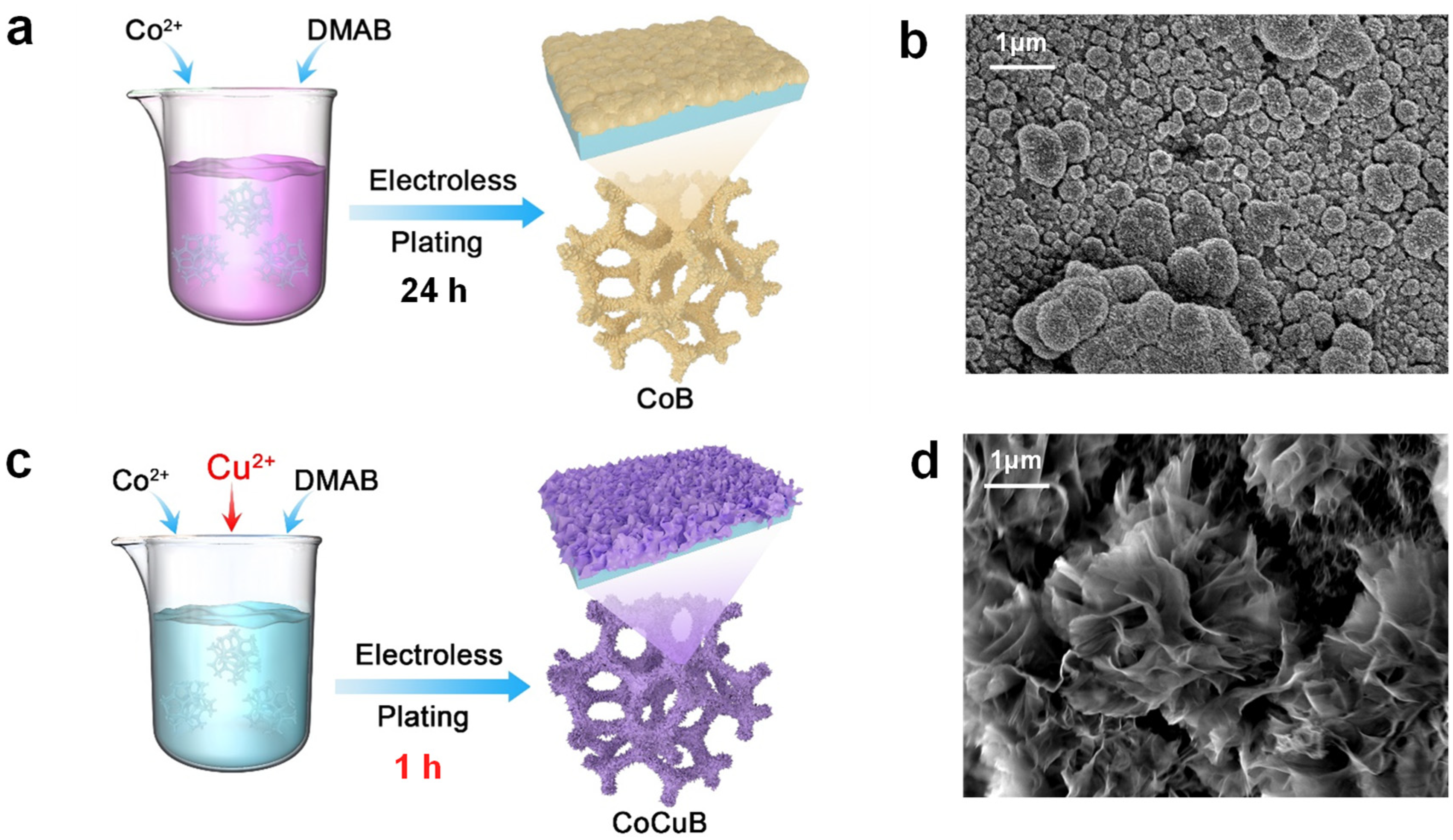
2.2. Synthesis of Co-B Catalyst

The synthesis of the Co-B monolithic catalyst was achieved through the electroless plating method, with 60 PPI PU foam serving as the base material. The foam, weighing 20 mg, was meticulously cleaned using ultrasonic treatment, first in ethanol and then in deionized water, with each stage lasting a total of 40 min to ensure the thorough removal of all impurities and unwanted substances. Subsequently, the cleansed PU foam was soaked in an activation solution composed of 20 mL of a mixture containing NiSO4·6H2O (200 mol mL−1) and 0.2 g of Me4NB3H8 for 30 min at 298.15 K. Subsequently, the foam was meticulously rinsed with deionized water.
After the activation phase, the pre-processed PU foam was submerged in 100 mL of solution specifically formulated for electroless plating, which contained CoSO4·7H2O (2.7 g), Na2SO4 (1.5 g), C4H4Na2O4 (2.5 g), and Et2NHBH3 (DMAB, 0.8 g). The foam was immersed in the prepared solution for 24 h at 333.15 K. After soaking for the chosen duration, the resulting Co-B catalyst was carefully washed with deionized water and then underwent vacuum drying at 333.15 K.

2.3. Synthesis of Co-Cu-B Catalyst

The synthesis of the Co-B monolithic catalyst was achieved through the electroless plating method, with 60 PPI PU foam serving as the base material. The foam, weighing 20 mg, was meticulously cleaned using ultrasonic treatment, first in ethanol and then in deionized water, with each stage lasting a total of 40 min to ensure the thorough removal of all impurities and unwanted substances. Subsequently, the cleansed PU foam was soaked in an activation solution composed of 20 mL of a mixture containing NiSO4·6H2O (200 mol mL−1) and 0.2 g of Me4NB3H8, for 30 min at 298.15 K. Subsequently, the foam was meticulously rinsed with deionized water.
After the activation phase, the pre-processed PU foam was submerged in 100 mL of solution specifically formulated for electroless plating, which contained with CoSO4·7H2O (2.7 g), CuSO4 (0.04 g), Na2SO4 (1.5 g), C4H4Na2O4 (2.5 g), and DMAB (0.8 g). The foam was immersed in the prepared solution for 1 h at 298.15 K. After soaking, the synthesized Co-Cu-B catalyst was thoroughly cleaned with deionized water and then vacuum-dried at a temperature of 333.15 K.

2.4. Characterization of Materials

Scanning electron microscopy (SEM) images were captured using a HITACHI FE-SEM-4800 microscope operated at an accelerating voltage of 1 kV. Transmission electron microscopy (TEM) images and associated energy-dispersive X-ray spectroscopy (EDS) elemental mappings were obtained with a Tecnai G2 20 TWIN TEM and a JEOL JEM-2100F TEM, both operated at 200 kV. X-ray photoelectron spectroscopy (XPS) analysis was performed on a VG ESCALAB 220I-XL instrument, with XPS spectra calibrated against the C1s peak at 284.8 eV. The specific surface areas of the samples were measured by Brunauer–Emmett–Teller (BET) analysis using a Micromeritics ASAP 2460 surface area and porosity analyzer. Inductively coupled plasma atomic emission spectroscopy (ICP-AES) was conducted with an Optima 7300DVICP-AES Perkin Elmer spectrometer. X-ray diffraction (XRD) patterns were obtained using a MiniFlex600 instrument (Rigaku Corporation, Tokyo, Japan) equipped with Cu-Kα radiation.

2.5. Reaction Parameter Evaluation

The catalytic performance of the Co-B and Co-Cu-B catalysts was assessed by quantifying the hydrogen generation rate (HGR) during the hydrolysis of a NaBH4 solution. Experiments were carried out in a double-walled flask connected to a water bath to ensure a constant temperature. The quantity of hydrogen produced during the dehydrogenation process was measured using a water displacement technique. During a typical catalytic activity assessment, 100 mL of NaBH4 solution was poured into a flask, after which 0.17 g of the catalyst was introduced. Unless otherwise specified, all test temperatures were set at 308.15 K. The impact of varying NaBH4 concentrations (5 wt.% to 15 wt.%) and a constant NaOH concentration (10 wt.%) on hydrogen production efficiency was examined using 0.17 g of the Co-Cu-B catalyst. To determine the activation energy (Ea), reactions with the alkaline NaBH4 solution were performed at different temperatures: 288.15 K, 298.15 K, 308.15 K, and 318.15 K.
For the durability assessment, 0.17 g of the catalyst was submerged in 100 mL of an alkaline solution consisting of 10 wt.% NaBH4 and 10 wt.% NaOH. The reaction underwent ten cycles, each involving the replacement of an equal volume of the NaBH4 alkaline solution. After each cycle of testing, the catalyst was retrieved from the solution and subjected to a purification process involving rinsing with distilled water, drying, and re-weighing, after which the next experimental iteration commenced.

3. Results and Discussion

3.1. Material Characterization

The monolithic Co-B catalyst was fabricated on PU foam through an EP process, as shown in Figure 1a. A comparable technique was employed to synthesize monolithic Co-Cu-B catalysts on PU foam, as shown in Figure 1c. Remarkably, the Co-Cu-B catalyst was essentially fully coated onto the PU foam in just 1 h, as shown in Figure S1. By comparison, the Co-B sample had not yet fully covered the PU foam surface after 1 h, as shown in Figure S2, which may have been due to the addition of copper in the catalyst, which greatly shortened the etching time.
As evidenced by the SEM images, the monolithic Co-B catalyst maintained the structural integrity of the PU foam and exhibited a spherical morphology, as illustrated in Figure 1b. The Co-Cu-B catalyst exhibited a distinct flower-like structure as demonstrated in Figure 1d. The abundant petals meticulously arranged during electroless plating originated from a common central region, resulting in its distinctive nanoflower-like morphology, which potentially contributed to the significantly increased surface area. When juxtaposed with Figure S4 and Figure 1d, it becomes apparent that the nanoflower structure of the Co-Cu-B catalyst was maintained during the entire reaction. It should be noted that the observed morphological differences can be ascribed to the variations in the kinetics of nucleation and deposition during catalyst formation [38].
As shown in Table S1, the BET surface area of the Co-Cu-B catalyst was observed to be 10.73 m2 g−1, which is roughly twice that of the Co-B catalyst. Additionally, the total pore volume of the Co-Cu-B catalyst was measured at 0.043 cm3 g−1, which is approximately fourfold higher than that of the Co-B catalyst. The mean pore diameter of the Co-Cu-B catalyst was found to be 16.17 nm, approximately twice the diameter of the Co-B catalyst. These findings imply that the Co-Cu-B catalyst exhibited a greater surface area and a more developed pore network, which enhanced the interaction between the catalyst and the reaction solution. Furthermore, the substantial variation in these results signifies the effective integration of Cu into the catalyst structure.
According to the ICP results in Table S2, the proportion of Co, Cu, and B in the Co-Cu-B sample was determined to be 33:4:10, indicating the successful incorporation of Cu. The structural characteristics of the synthesized Co-Cu-B sample were comprehensively evaluated using TEM techniques. The TEM image in Figure 2a, at various magnifications, confirms that the nanoflower morphology of Co-Cu-B was constituted by ultrathin nanosheets, in agreement with the findings from SEM. EDS revealed a homogeneous distribution of Co, B, and Cu across the catalyst surface.
XPS analysis was conducted to elucidate the electronic configuration and chemical nature of the catalysts. The XPS analysis, as shown in Figure 2d–f, revealed the valence state of Co within the Co-Cu-B catalyst. In Figure 2d, the peaks at 797.1 eV and 781.1 eV correspond to Co 2p1/2 and Co 2p3/2. The peaks at 797.3 eV and 782.2 eV are in agreement with Co2+, while the two peaks at 795.5 eV and 780.4 eV correspond to Co3+. The satellite peaks at 805.8 eV and 790.0 eV belong to Co2+, while the satellite peaks at 800.8 eV and 785.8 eV were attributed to Co3+ [39]. In the Cu2p region of the XPS spectrum (Figure 2e), five peaks can be observed, with the two main peaks at 951.9 eV and 932.1 eV attributed to Cu0 in the Cu 2p1/2 and Cu 2p3/2 regions, respectively. The binding energy at 945.1 eV was identified as a satellite peak of Cu2+, and the two peaks at 954.1 eV and 934.5 eV were attributed to Cu2+ [37]. Additionally, in the B 1s XPS spectrum, the peak at 191.2 eV indicates the presence of oxidized B within the Co-Cu-B catalyst [30].
The XPS analysis, depicted in Figure S5, revealed the valence state of Co in the Co-B catalyst. Two primary peaks can be observed at 797.6 eV and 781.5 eV, corresponding to Co 2p1/2 and Co 2p3/2. In the Co 2p1/2 region, the two deconvoluted peaks at 797.8 eV and 796.0 eV were attributed to Co2+ and Co3+. Similarly, in the Co 2p3/2 region, the deconvoluted peaks can be found at 782.7 eV and 780.9 eV, corresponding to Co2+ and Co3+. The satellite peaks of Co3+ are at 803.1 eV and 786.9 eV [39].
Figure S6 displays the XRD pattern, which offers the crystallographic makeup of the Co-Cu-B catalyst. The pattern features distinct diffraction peaks, signaling a well-organized crystalline arrangement within the sample. These peaks were analyzed and cross-referenced with the Joint Committee on Powder Diffraction Standards (JCPDS) database to determine the phases present.
The diffraction peaks corresponding to the Co and Cu phases were matched to Co(OH)2 and Cu, respectively. The detection of Co(OH)2 hints at the catalyst’s potential exposure to a hydroxyl-rich environment during synthesis or handling. The Cu phase is suspected to be metallic Cu, which is vital for the catalyst’s reduced state and its catalytic performance.
In contrast, the diffraction peaks associated with B are less intense, suggesting that B may exist in an amorphous state or as microcrystalline particles too small to generate strong diffraction signals. The weak B peaks could also imply uneven distribution within the catalyst or integration into the crystal lattices of the Co and Cu phases.
In summary, the findings highlight a predominant presence of Co2+ species on the surfaces of both the Co-Cu-B and Co-B catalysts. Notably, the Co 2p binding energy for the Co-Cu-B catalyst was lower than that of the Co-B catalyst, suggesting that the addition of Cu alters the electronic environment at the Co active sites. The surface electronic states of both Co and Cu within the Co-Cu-B catalyst experienced notable alterations. Furthermore, the expanded unique catalyst surface area resulted in a greater exposure of Co hydroxides and Cu0 species on the surface of the novel 3D flower structure. This increase in surface area potentially offered a more diverse array of electron-rich and electron-deficient adsorption sites, which can be advantageous for catalytic processes [37].

3.2. Catalytic Performance

Figure 3 evaluates the catalytic effectiveness and activation energy of the Co-Cu-B and Co-B catalysts in the hydrolysis of NaBH4. Figure 3a illustrates the impact of varying NaBH4 concentrations on the catalytic behavior of both catalysts. In the presence of 5 wt.%, 10 wt.%, and 15 wt.% NaBH4, along with 10 wt.% sodium hydroxide (NaOH), the HGR for the Co-Cu-B catalyst was determined to be 3.16 L min−1 g−1, 3.93 L min−1 g−1, and 2.96 L min−1 g−1, respectively. In comparison, the HGR for the Co-B catalyst was 0.21 L min−1 g−1, 0.28 L min−1 g−1, and 0.22 L min−1 g−1 under the same conditions. These findings suggest that the Co-Cu-B catalyst outperformed the Co-B catalyst in terms of catalytic efficiency under equivalent settings. Both catalysts achieved their peak performance in a solution comprising 10 wt.% NaBH4 and 10 wt.% NaOH. The reduced hydrogen generation rates at lower NaBH4 concentrations can be attributed to the underutilization of the catalyst’s active sites. Conversely, at high NaBH4 concentrations, increased solution viscosity and diffusion resistances can hinder catalytic activity. Additionally, the emergence of by-products that may adhere to the catalyst’s surface and obstruct active sites can result in a decline in the catalyst’s efficiency for hydrogen production via hydrolysis [10]. The key factor for application is the catalyst’s stability and its capacity for repeated use [1].
Figure 3b illustrates the performance of the Co-Cu-B and Co-B catalysts over a series of ten operational cycles. The Co-Cu-B sample, with an initial HGR of 3.93 L min−1 g−1, retained 80% of its original activity by the tenth cycle. This suggests that, despite a slight decrease in hydrogen production, the catalyst maintained a relatively high level of activity. In contrast, the Co-B catalyst, which started with a lower HGR of 0.28 L min−1 g−1, experienced a marked decline in catalytic performance with each subsequent cycle, with the rate declining to 75% of its initial value by the third cycle and further dropping to 55% by the tenth cycle. These findings demonstrate that the Co-Cu-B catalyst has excellent durability.
To understand the thermodynamic aspects of the hydrolysis reactions, the hydrolysis process of NaBH4 was examined across a temperature spectrum of 288.15 K to 318.15 K. Figure 3c illustrates the HGRs of the Co-Cu-B sample, which were determined to be 0.98 L min−1 g−1, 2.04 L min−1 g−1, 3.92 L min−1 g−1, and 5.95 L min−1 g−1 at temperatures of 288.15 K, 298.15 K, 308.15 K, and 318.15 K, respectively. In comparison, the Co-B catalyst exhibited HGR values of 0.05 L min−1 g−1, 0.10 L min−1 g−1, 0.28 L min−1 g−1, and 0.50 L min−1 g−1 at the same temperatures. The increasing hydrogen generation rates with increasing temperature align with the expected trend, signifying a positive influence of temperature on the catalytic efficacy. Throughout the temperature range, the Co-Cu-B catalyst consistently demonstrated superior hydrolysis performance compared to the Co-B catalyst.
Moreover, Arrhenius plots (ln k versus 1/T) were constructed using the HGR obtained at various temperatures for the hydrolysis reaction. These plots enable the determination of the apparent Ea of the catalytic reaction, as defined by the following thermodynamic equation:
ln k = ln A − (Ea/(R × T))
Here, k represents the reaction rate constant (mol·min−1·g−1), A is the frequency factor, Ea is the activation energy (kJ·mol−1), R is the universal gas constant (8.314 J·K−1·mol−1), and T is the absolute temperature (K) [40].
For the Co-Cu-B catalyst, as illustrated in Figure 3c, the slope of the linear portion of the Arrhenius plot is −5573.8. Consequently, utilizing the aforementioned Arrhenius equation, the Ea value for the Co-Cu-B catalyst in the hydrolysis of NaBH4 was calculated to be 46.34 kJ·mol−1. Similarly, for the Co-B catalyst, as depicted in Figure 3d, the slope of the linear portion of the Arrhenius plot is −7256.1, leading to an Ea value of 60.33 kJ·mol−1. The Co-Cu-B catalyst exhibited a relatively lower Ea value, suggesting enhanced catalytic efficiency in the hydrolysis of NaBH4.
Figure 3e illustrates the energy pathway and structural changes in B-H bond dissociation in adsorbed BH3 on Co-B and Co-Cu-B surfaces. CI-NEB calculations revealed key barriers and reaction energies, combined with adsorption configuration analysis. On the Co-B surface, B-H bond dissociation in BH3 required overcoming a barrier of 0.44 eV and was an endothermic process (+0.14 eV). The shorter B-H bond length (1.296 Å) in the initial adsorption configuration indicated a more stable B-H bond, which likely contributed to the higher dissociation barrier. In contrast, on the Co-Cu-B surface, the B-H bond dissociation barrier in BH3 significantly decreased to 0.16 eV, and the reaction became exothermic (−0.32 eV). The longer B-H bond length (1.366 Å) in the initial adsorption configuration suggested a relatively weaker B-H bond, facilitating the lower dissociation barrier. These findings indicate that the Co-Cu-B catalyst’s surface, compared to that of the Co-B catalyst, optimized the surface electronic structure, exhibiting a significantly lower Ea for the B-H bond dissociation of BH3. This reduction in Ea markedly enhanced catalytic activity, providing theoretical support for designing more efficient catalysts based on Co-Cu-B materials.
Table S3 presents the intrinsic activity data for the Co-B and Co-Cu-B catalysts, measured in terms of active area and active mass. The Co-B catalyst exhibited intrinsic activity of 0.054 L min−1 m−1 (active area) and 0.282 L min−1 g−1 (active mass). In contrast, the Co-Cu-B catalyst demonstrated significantly higher intrinsic activity, with values of 0.366 L min−1 m−1 and 4.123 L min−1 g−1 for active area and active mass, respectively.
The marked enhancement in intrinsic activity observed for the Co-Cu-B catalyst suggests that the addition of Cu to the Co-B system significantly improved the catalytic efficiency. This increase in activity can likely be explained by the synergistic effects arising from the interaction between Co and Cu species, leading to enhanced surface reactivity and/or improved catalyst stability.
The increased active mass value of the Co-Cu-B catalyst suggests that it exhibited greater efficiency on a mass basis. This trait is particularly advantageous in industrial contexts where the cost and consumption of catalysts are considerable factors.
These results underscore the importance of catalyst composition in determining the intrinsic activity and highlight the potential of the Co-Cu-B system for application in catalytic processes requiring high efficiency and selectivity.
Table S4 compiles the HGR and Ea for the hydrolysis of NaBH4 facilitated by diverse Co-based, self-supported catalysts. It is evident that the HGR achieved in this study is superior to those of other reported catalysts. Additionally, the observed Ea is notably lower than that of most other catalysts. Consequently, this suggests that the as-synthesized Co-Cu-B catalyst supported on ambient temperature serves as an effective, inexpensive catalyst for the hydrolysis of NaBH4.

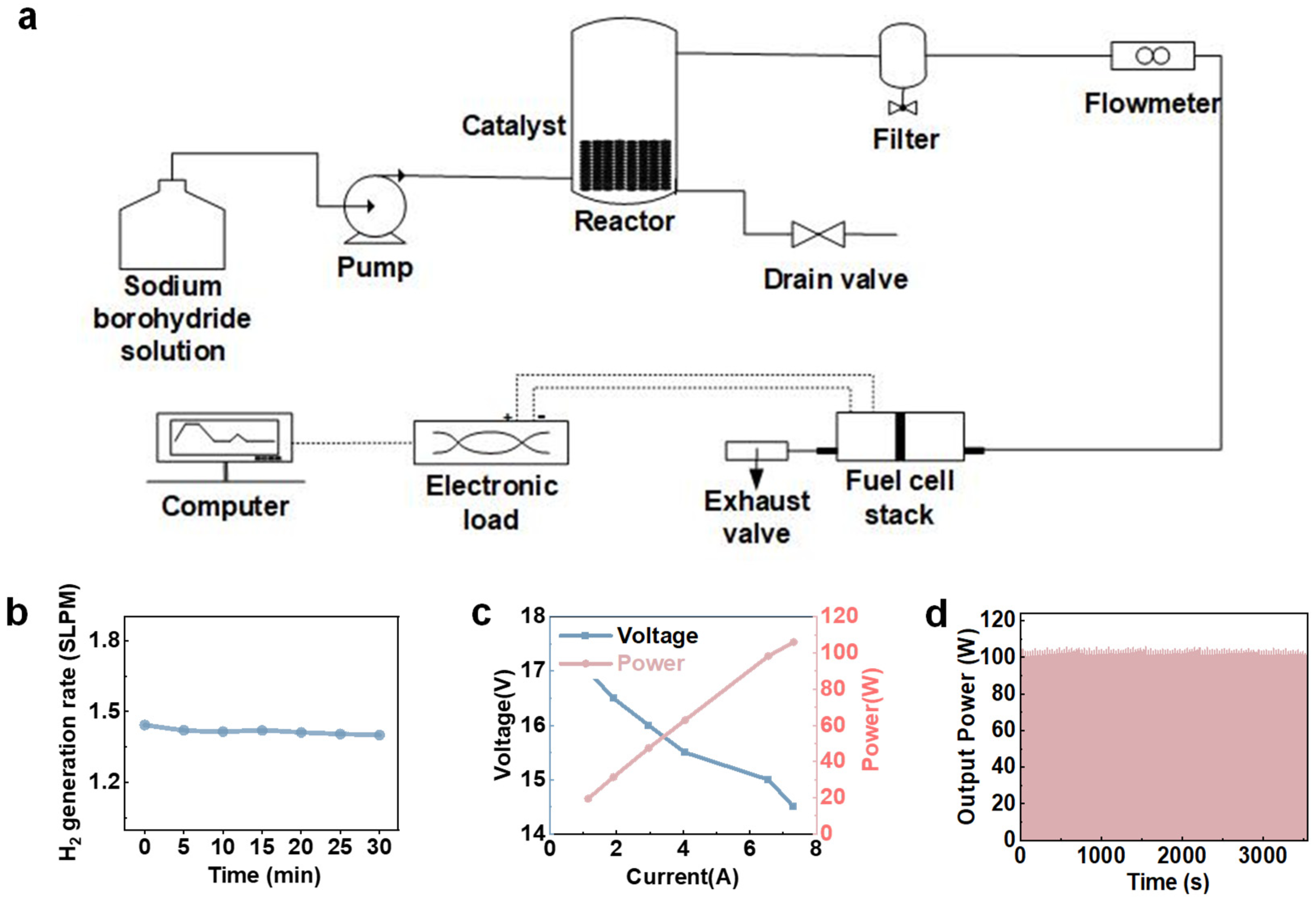
3.3. H2 Supply System Application

Finally, we integrated the monolithic Co-Cu-B catalyst into hydrogen fuel cell systems to evaluate its ability in such an application. Figure 4a illustrates a schematic of an integrated system meticulously designed for hydrogen production and its subsequent use in a fuel cell stack. Central to this system is the reactor, wherein the selected catalyst expedites the hydrolysis of NaBH4, thereby efficiently producing hydrogen. The resultant pure hydrogen is channeled to the fuel cell stack, undergoing an electrochemical reaction to yield electricity. A flowmeter reads the records of reactant flow rates and an exhaust valve for safe post-reaction gas release. Notably, an electronic load tests the current, voltage, and power of fuel cell system under different working conditions. A specialized computer system monitors the operation, adjusting parameters for peak performance and aggregating essential data for subsequent analysis.
Precise control of the HGR is critical for meeting the varied demands of fuel cell technologies. Figure 4b demonstrates that by modulating the solution entry speed, the hydrogen flow could be consistently maintained at approximately 1.4 L min−1. The hydrogen production rate was maintained to sustain a minimum power output of 100 W when utilized in a commercial PEMFC stack, showcasing its remarkable potential for industrial applications.
Figure 4c illustrates that the system can sustainably deliver electrical energy within the power range of 0 to 100 W. The power output of the PEMFC was modulated by adjusting the current drawn by the electronic load. This demonstrates that the hydrogen generation system can effectively synchronize with the power output of the fuel cell stack to facilitate efficient and stable hydrogen production.
As illustrated in Figure 4d, the PEMFC stack functioned for a duration of 60 min under a consistent power output of 100 W, demonstrating stability in its power output for the entire process. Consequently, hydrogen gas was generated via catalytic hydrolysis of NaBH4, enabled by the efficient and stable catalyst. This helps to improve the performance of the total fuel cell system. Moreover, when synchronized with periodic drainage, the system is capable of providing a continuous electrical output over a prolonged timeframe. This catalyst can be rapidly and effortlessly integrated into existing hydrogen fuel cell systems, thereby offering a pathway to cost-effective deployment.

4. Conclusions

In summary, our study successfully achieved Cu doping through the electroless plating method, culminating in the creation of a unique Co-Cu-B monolithic self-supported catalyst. This catalyst was deposited on the surface of polyurethane foam, characterized by a 3D flower-like microporous surface morphology, and exhibited enhanced catalytic efficiency for the hydrolytic decomposition of NaBH4. The HGR of this catalyst was 3.92 L min−1 g−1 in a solution containing 10 wt.% sodium borohydride and 10 wt.% sodium hydroxide. BET analysis indicated that the Co-Cu-B catalyst possessed a specific surface area of 10.73 m2 g−1, approximately double that of the Co-B catalyst. XPS analysis revealed an increased exposure of Co hydroxides and Cu0 on the surface of the newly formed 3D-flower-structured catalyst, which could potentially accelerate NaBH4 hydrolysis. Additionally, the Co-Cu-B catalyst retained 80% of its initial activity following ten consecutive cycles. Activation energy assessments showed that the Co-Cu-B catalyst exhibited a lower Ea of 45.73 kJ mol−1 in contrast to the Co-B sample, underscoring its enhanced catalytic efficiency in NaBH4 hydrolysis. The study adeptly modulated the HGR (1.4 L min−1) by varying the NaBH4 concentration and feed rate. The generated hydrogen was efficiently harnessed in a PEMFC stack to produce stable electrical power ranging from 0 to 100 W. This highly efficient monolithic Co-Cu-B catalyst offers feasible strategies for hydrogen energy storage and utilization in hydrogen fuel cell systems.

Supplementary Materials

The following supporting information can be downloaded at: https://www.mdpi.com/article/10.3390/pr12071384/s1, Table S1: BET results of Co-Cu-B and Co-B. Table S2. ICP-AES results of Co-B and Co-Cu-B. Table S3: Intrinsic activity results of Co-B and Co-Cu-B catalysts. Figure S1: SEM image of Co-Cu-B sample after synthesis for 1 h. Figure S2: SEM image of Co-B sample after synthesis for 1 h. Figure S3: SEM image of Co-B catalyst after synthesis for 24 h. Figure S4: SEM image of Co-Cu-B catalyst before reaction. Figure S5: High-resolution XPS spectra of Co 2p for the Co-B catalyst. Figure S6: XRD analysis of the Co-Cu-B catalyst. Table S4: HGR and Ea for NaBH4 hydrolysis by diverse Co-based, self-supported catalysts [41,42,43,44,45,46].

Author Contributions

Conceptualization, W.Y.; methodology, W.Y., X.Y., and C.L.; formal analysis, W.Y., L.X., W.N. and Q.Y.; investigation, W.Y. and Y.Z.; resources, W.Y. and J.H.; data curation, W.Y.; writing—original draft preparation, W.Y. and C.L.; writing—review and editing, B.Z. and W.G.; supervision, B.Z. and W.G.; project administration, B.Z.; funding acquisition, B.Z. All authors have read and agreed to the published version of the manuscript.

Funding

This work was supported by NSFC (22279019) and STCSM (21DZ1207102, 21DZ1207103).

Data Availability Statement

Data are contained within the article and Supplementary Materials.

Acknowledgments

The authors extend their gratitude to the associate editor and the reviewers for their insightful feedback, which significantly enhanced the quality of this paper. The authors also acknowledge Yanhui Guo for his enlightening discussions. Furthermore, the authors thank Qi Wang from Shiyanjia Lab (www.shiyanjia.com, accessed on 5th March 2024) for her assistance with the XPS analysis.

Conflicts of Interest

The authors declare no conflicts of interest.

References

  1. Ruslan, N.; Yahya, M.S.; Siddique, M.N.I.; Yengantiwar, A.P.; Ismail, M.; Awal, M.R.; Mohd Yusoff, M.Z.; Abdul Halim Yap, M.F.A.; Mustafa, N.S. Review on Magnesium Hydride and Sodium Borohydride Hydrolysis for Hydrogen Production. Crystals 2022, 12, 1376. [Google Scholar] [CrossRef]
  2. Abdelhamid, H.N. A Review on Hydrogen Generation from the Hydrolysis of Sodium Borohydride. Int. J. Hydrogen Energy 2021, 46, 726–765. [Google Scholar] [CrossRef]
  3. Yao, Q.; Zhang, X.; Lu, Z.-H.; Xu, Q. Metal-Organic Framework-Based Catalysts for Hydrogen Production from Liquid-Phase Chemical Hydrides. Coord. Chem. Rev. 2023, 493, 215302. [Google Scholar] [CrossRef]
  4. Xu, D.; Zhang, Y.; Guo, Q. Research Progress on Catalysts for Hydrogen Generation through Sodium Borohydride Alcoholysis. Int. J. Hydrogen Energy 2021, 47, 5929–5946. [Google Scholar] [CrossRef]
  5. Long, B.; Chen, J.; Sharshir, S.W.; Ibrahim, L.; Zhou, W.; Wang, C.; Wang, L.; Yuan, Z. The Mechanism and Challenges of Cobalt-Boron-Based Catalysts in the Hydrolysis of Sodium Borohydride. J. Mater. Chem. A 2024, 12, 5606–5625. [Google Scholar] [CrossRef]
  6. Wang, T.; Jiang, T.; Zhang, H.; Zhao, Y. Advances in Catalysts for Hydrogen Production by Methanolysis of Sodium Borohydride. Int. J. Hydrogen Energy 2022, 47, 14589–14610. [Google Scholar] [CrossRef]
  7. Schlesinger, H.I.; Brown, H.C.; Finholt, A.E.; Gilbreath, J.R.; Hoekstra, H.R.; Hyde, E.K. Sodium Borohydride, Its Hydrolysis and Its Use as a Reducing Agent and in the Generation of Hydrogen1. J. Am. Chem. Soc. 1953, 75, 215–219. [Google Scholar] [CrossRef]
  8. Baytar, O.; Şahin, Ö.; Ekinci, A. Effect of Environmentally Friendly and Efficient Metal-Free Hydrochars as Catalysts on Sodium Borohydride Hydrolysis. Fuel 2023, 346, 128308. [Google Scholar] [CrossRef]
  9. Rong Weiren, Q.D. Decomposition of Borohydride Solution and Stabilization Mechanism of NaOH. J. Fudan Univ. Sci. 1998, 3, 276–278. [Google Scholar] [CrossRef]
  10. Sun, Q.; Wang, N.; Xu, Q.; Yu, J. Nanopore-Supported Metal Nanocatalysts for Efficient Hydrogen Generation from Liquid-Phase Chemical Hydrogen Storage Materials. Adv. Mater. 2020, 32, 2001818. [Google Scholar] [CrossRef]
  11. Zhang, Y.; Zou, J.; Luo, Y.; Wang, F. Study on Preparation and Performance of Ru-Fe/GO Catalyst for Sodium Borohydride Alcoholysis to Produce Hydrogen. Fuller. Nanotub. Carbon Nanostructures 2020, 28, 786–793. [Google Scholar] [CrossRef]
  12. Arzac, G.M.; Paladini, M.; Godinho, V.; Beltrán, A.M.; Jiménez de Haro, M.C.; Fernández, A. Strong Activation Effect on a Ru-Co-c Thin Film Catalyst for the Hydrolysis of Sodium Borohydride. Sci. Rep. 2018, 8, 9755. [Google Scholar] [CrossRef]
  13. Chowdhury, A.D.; Agnihotri, N.; De, A. Hydrolysis of Sodium Borohydride Using Ru–Co-PEDOT Nanocomposites as Catalyst. Chem. Eng. J. 2015, 264, 531–537. [Google Scholar] [CrossRef]
  14. Rakap, M.; Özkar, S. Intrazeolite Cobalt(0) Nanoclusters as Low-Cost and Reusable Catalyst for Hydrogen Generation from the Hydrolysis of Sodium Borohydride. Appl. Catal. B Environ. 2009, 91, 21–29. [Google Scholar] [CrossRef]
  15. Hirscher, M.; Yartys, V.A.; Baricco, M.; von Colbe, J.B.; Blanchard, D.; Bowman, R.C., Jr.; Broom, D.P.; Buckley, C.E.; Chang, F.; Chen, P.; et al. Materials for Hydrogen-Based Energy Storage—Past, Recent Progress and Future Outlook. J. Alloys Compd. 2020, 827, 153548. [Google Scholar] [CrossRef]
  16. Li, J.; Hong, X.; Wang, Y.; Luo, Y.; Huang, P.; Li, B.; Zhang, K.; Zou, Y.; Sun, L.; Xu, F.; et al. Encapsulated Cobalt Nanoparticles as a Recoverable Catalyst for the Hydrolysis of Sodium Borohydride. Energy Storage Mater. 2020, 27, 187–197. [Google Scholar] [CrossRef]
  17. Ganesan, K.; Hayagreevan, C.; Rahul, R.; Jeevagan, A.J.; Adinaveen, T.; Bhuvaneshwari, D.S.; Muthukumar, P.; Amalraj, M. Catalytic Hydrolysis of Sodium Borohydride for Hydrogen Production Using Phosphorylated Silica Particles. Environ. Sci. Pollut. Res. 2022, 30, 21199–21212. [Google Scholar] [CrossRef] [PubMed]
  18. Eugénio, S.; Demirci, U.B.; Silva, T.M.; Carmezim, M.J.; Montemor, M.F. Copper-Cobalt Foams as Active and Stable Catalysts for Hydrogen Release by Hydrolysis of Sodium Borohydride. Int. J. Hydrogen Energy 2016, 41, 8438–8448. [Google Scholar] [CrossRef]
  19. Obligacion, J.V.; Chirik, P.J. Earth-Abundant Transition Metal Catalysts for Alkene Hydrosilylation and Hydroboration. Nat. Rev. Chem. 2018, 2, 15–34. [Google Scholar] [CrossRef]
  20. Wang, L.; Nitopi, S.; Wong, A.B.; Snider, J.L.; Nielander, A.C.; Morales-Guio, C.G.; Orazov, M.; Higgins, D.C.; Hahn, C.; Jaramillo, T.F. Electrochemically Converting Carbon Monoxide to Liquid Fuels by Directing Selectivity with Electrode Surface Area. Nat. Catal. 2019, 2, 702–708. [Google Scholar] [CrossRef]
  21. Koh, J.S.; Kim, D.H.; Lee, S.H.; Kim, M.S. Hydrogen Generation System for Fuel Cells Based on High Pressure Hydrolysis of Solid-State Sodium Borohydride. Energy Convers. Manag. 2023, 281, 116850. [Google Scholar] [CrossRef]
  22. Paksoy, A.; Kurtoğlu, S.F.; Dizaji, A.K.; Altıntaş, Z.; Khoshsima, S.; Uzun, A.; Balcı, Ö. Nanocrystalline Cobalt–Nickel–Boron (Metal Boride) Catalysts for Efficient Hydrogen Production from the Hydrolysis of Sodium Borohydride. Int. J. Hydrogen Energy 2021, 46, 7974–7988. [Google Scholar] [CrossRef]
  23. Shen, X.; Dai, M.; Gao, M.; Zhao, B.; Ding, W. Solvent Effects in the Synthesis of CoB Catalysts on Hydrogen Generation from Hydrolysis of Sodium Borohydride. Chin. J. Catal. 2013, 34, 979–985. [Google Scholar] [CrossRef]
  24. Paksoy, A.; Kurtoğlu-Öztulum, S.F.; Yağcı, M.B.; Balcı-Çağıran, Ö. Low-Cost and Reusable Iron- and Nickel-Based Metal Boride Nanoparticles for Efficient Catalytic Hydrolysis of Sodium Borohydride. Int. J. Hydrogen Energy 2022, 47, 36898–36913. [Google Scholar] [CrossRef]
  25. Liu, J.; Li, B.; Dong, Y.; Liu, Q.; Song, Y.; Guo, Y.; Zhao, Y.; Li, X.; Xiong, J. Hydrolysis of Ammonia Borane for Hydrogen Generation on Bimetallic CoCu Catalysts: Regulation of Synergistic Effect. Catal. Lett. 2024, 154, 461–472. [Google Scholar] [CrossRef]
  26. Ding, X.-L.; Yuan, X.; Jia, C.; Ma, Z.-F. Hydrogen Generation from Catalytic Hydrolysis of Sodium Borohydride Solution Using Cobalt–Copper–Boride (Co–Cu–B) Catalysts. Int. J. Hydrogen Energy 2010, 35, 11077–11084. [Google Scholar] [CrossRef]
  27. Wang, Y.; Zou, K.; Zhang, D.; Cao, Z.; Zhang, K.; Xie, Y.; Zhou, G.; Li, G.; Bai, S. Cobalt–Copper–Boron Nanoparticles as Catalysts for the Efficient Hydrolysis of Alkaline Sodium Borohydride Solution. Int. J. Hydrogen Energy 2020, 45, 9845–9853. [Google Scholar] [CrossRef]
  28. Liu, H.; Shi, Q.; Yang, Y.; Yu, Y.-N.; Zhang, Y.; Zhang, M.; Wei, L.; Lu, Y. CoO-Co2P Composite Nanosheets as Highly Active Catalysts for Sodium Borohydride Hydrolysis to Generate Hydrogen. Funct. Mater. Lett. 2020, 13, 2051025. [Google Scholar] [CrossRef]
  29. Wang, Y.; Shen, Y.; Qi, K.; Cao, Z.; Zhang, K.; Wu, S. Nanostructured Cobalt–Phosphorous Catalysts for Hydrogen Generation from Hydrolysis of Sodium Borohydride Solution. Renew. Energy 2016, 13, 6. [Google Scholar] [CrossRef]
  30. Han, J.; Yuan, W.; Wei, M.; Zhang, B.; Guo, Y. Real-Time Tunable Hydrogen Generation from Hydrolysis of Borohydrides Using 3D Magnetic Catalysts. Inorg. Chem. Front. 2023, 10, 1876–1886. [Google Scholar] [CrossRef]
  31. Paladini, M.; Arzac, G.M.; Godinho, V.; Haro, M.C.J.D.; Fernández, A. Supported Co Catalysts Prepared as Thin Films by Magnetron Sputtering for Sodium Borohydride and Ammonia Borane Hydrolysis. Appl. Catal. B Environ. 2014, 158, 400–409. [Google Scholar] [CrossRef]
  32. Faghihi, M.; Akbarbandari, F.; Zabihi, M.; Pazouki, M. Synthesis and Characterization of the Magnetic Supported Metal-Organic Framework Catalysts (CuCoBTC@MAC and CuBTC@MAC) for the Hydrogen Production from Sodium Borohydride. Mater. Chem. Phys. 2021, 267, 124599. [Google Scholar] [CrossRef]
  33. Wei, M.; Han, J.; Wu, Q.; Li, J.; Ji, Z.; Li, Z.; Liang, J.; Guo, Y. Monolithic CoMoB Based Catalyst Enabling High Water-Sources Adaptive Hydrolysis of Borohydrides. Chem. Eng. J. 2024, 482, 148879. [Google Scholar] [CrossRef]
  34. Han, J.; Niu, W.; Yuan, W.; Wei, M.; Zhang, B.; Guo, Y. Rational 3D Structure of Monolithic Catalysts for Enhanced Hydrolytic Dehydrogenation of Ammonia Borane. ACS Sustain. Chem. Eng. 2023, 11, 8462–8473. [Google Scholar] [CrossRef]
  35. Zhuang, D.-W.; Dai, H.-B.; Zhong, Y.-J.; Sun, L.-X.; Wang, P. A New Reactivation Method towards Deactivation of Honeycomb Ceramic Monolith Supported Cobalt–Molybdenum–Boron Catalyst in Hydrolysis of Sodium Borohydride. Int. J. Hydrogen Energy 2015, 40, 9373–9381. [Google Scholar] [CrossRef]
  36. Zhang, X.; Wang, J.; Tan, B.; Li, Z.; Cui, Y.; He, G. Ce-Co Catalyst with High Surface Area and Uniform Mesoporous Channels Prepared by Template Method for Hg0 Oxidation. Catal. Commun. 2017, 98, 5–8. [Google Scholar] [CrossRef]
  37. Lu, C.; Geng, H.; Zhu, Y.; Ma, J.; Wang, R.; Liu, X.; Tu, G. 3D Flower-Shape Co/Cu Bimetallic Nanocomposites with Excellent Wideband Electromagnetic Microwave Absorption. Appl. Surf. Sci. 2023, 615, 156219. [Google Scholar] [CrossRef]
  38. Wu, K.-J.; Tse, E.C.M.; Shang, C.; Guo, Z. Nucleation and Growth in Solution Synthesis of Nanostructures—From Fundamentals to Advanced Applications. Prog. Mater. Sci. 2022, 123, 100821. [Google Scholar] [CrossRef]
  39. Ji, L.; Lin, J.; Zeng, H.C. Metal−Support Interactions in Co/Al 2 O 3 Catalysts: A Comparative Study on Reactivity of Support. J. Phys. Chem. B 2000, 104, 1783–1790. [Google Scholar] [CrossRef]
  40. Balčiūnaitė, A.; Sukackienė, Z.; Antanavičiūtė, K.; Vaičiūnienė, J.; Naujokaitis, A.; Tamašauskaitė-Tamašiūnaitė, L.; Norkus, E. Investigation of Hydrogen Generation from Sodium Borohydride Using Different Cobalt Catalysts. Int. J. Hydrogen Energy 2021, 46, 1989–1996. [Google Scholar] [CrossRef]
  41. Zhang, X.; Zhao, J.; Cheng, F.; Liang, J.; Tao, Z.; Chen, J. Electroless-Deposited Co–P Catalysts for Hydrogen Generation from Alkaline NaBH4 Solution. Int. J. Hydrog. Energy 2010, 35, 8363–8369. [Google Scholar] [CrossRef]
  42. Oh, T.H.; Kwon, S. Effect of Manufacturing Conditions on Properties of Electroless Deposited Co–P/Ni Foam Catalyst for Hydrolysis of Sodium Borohydride Solution. Int. J. Hydrog. Energy 2012, 37, 15925–15937. [Google Scholar] [CrossRef]
  43. Wei, Y.; Wang, M.; Fu, W.; Si, S.; Wei, L.; Zhao, X.; Wang, Y. Mn Doped CoP/Ni Foam Catalyst for Hydrogen Generation from Hydrolysis of Sodium Borohydride. Mater. Lett. 2022, 308, 131166. [Google Scholar] [CrossRef]
  44. Wei, Y.; Huang, X.; Wang, J.; Yu, H.; Zhao, X.; Cheng, D. Synthesis of Bifunctional Non-Noble Monolithic Catalyst Co-W-P/Carbon Cloth for Sodium Borohydride Hydrolysis and Reduction of 4-Nitrophenol. Int. J. Hydrog. Energy 2017, 42, 25860–25868. [Google Scholar] [CrossRef]
  45. Guo, Y.; Dong, Z.; Cui, Z.; Zhang, X.; Ma, J. Promoting Effect of W Doped in Electrodeposited Co–P Catalysts for Hydrogen Generation from Alkaline NaBH4 Solution. Int. J. Hydrog. Energy 2012, 37, 1577–1583. [Google Scholar] [CrossRef]
  46. Wei, Y.; Wang, R.; Meng, L.; Wang, Y.; Li, G.; Xin, S.; Zhao, X.; Zhang, K. Hydrogen Generation from Alkaline NaBH4 Solution Using a Dandelion-like Co–Mo–B Catalyst Supported on Carbon Cloth. Int. J. Hydrog. Energy 2017, 42, 9945–9951. [Google Scholar] [CrossRef]
Figure 1. (a) Schematic representation of the synthesis process of the Co-B catalyst and its surface morphology. (b) SEM image of the Co-B catalyst. (c) Diagrammatic illustration of the fabrication process and surface characteristics of the Co-Cu-B catalyst. (d) SEM image of the Co-Cu-B catalyst.
Processes 12 01384 g001
Figure 2. (a) TEM image of Co-Cu-B. (b,c) The TEM images and corresponding EDS elemental mapping results for the Co-Cu-B catalyst. (df) XPS spectra further elucidate the chemical state of the catalyst, with (d) representing the Co 2p region, (e) the Cu 2p region, and (f) the B 1s region.
Processes 12 01384 g002
Figure 3. (a) HGR of the Co-Cu-B and Co-B catalysts at varying mass fractions of NaBH4. (b) Percentage comparison of the Co-Cu-B and Co-B catalysts’ activity after each reaction cycle relative to the initial activity. (c) Effect of temperature on the HGR of the Co-Cu-B catalyst, accompanied by an Arrhenius plot (inset). (d) Effect of temperature on the HGR of the Co-B catalyst, accompanied by a corresponding Arrhenius plot (inset). (e) CI-NEB calculation results for B-H bond dissociation of adsorbed BH3 on Co-Cu-B and Co-B surfaces. Energy profiles show initial state (IS), transition state (TS), and final state (FS) with dissociation barrier (Eb) and reaction energy (Er). Configurations of IS, TS, and FS structures are shown below. Atomic species: Co (blue), Cu (brown), B (pink), and H (white).
Processes 12 01384 g003
Figure 4. (a) Schematic illustration of Co-Cu-B catalyst-based fuel cell H2 supply system. (b) H2 generation rate of this system. (c) Co-Cu-B catalyst-based hydrogen supply system with varying power outputs for fuel cell system. (d) Long-term power output of fuel cells in the hydrogen supply system based on the Co-Cu-B catalyst.
Processes 12 01384 g004
Disclaimer/Publisher’s Note: The statements, opinions and data contained in all publications are solely those of the individual author(s) and contributor(s) and not of MDPI and/or the editor(s). MDPI and/or the editor(s) disclaim responsibility for any injury to people or property resulting from any ideas, methods, instructions or products referred to in the content.

