Article

Research on the Flow Characteristics in the Gap of a Variable-Speed Pump-Turbine in Pump Mode

1
Department of Energy and Power Engineering, Tsinghua University, Beijing 100084, China
2
Hebei Fengning Pumped Storage Energy Co., Ltd., Chengde 067000, China
*
Author to whom correspondence should be addressed.
Processes 2024, 12(7), 1424; https://doi.org/10.3390/pr12071424
Submission received: 17 February 2024 / Revised: 20 June 2024 / Accepted: 3 July 2024 / Published: 8 July 2024
(This article belongs to the Special Issue State-of-the-Art Energy Conversion and Storage)

Abstract

:
A variable-speed pump-turbine is the core component of a hydraulic storage and energy generation station. When the pump-turbine operates at a constant speed, its response to the power grid frequency is poor. In order to improve the hydraulic efficiency of the pumped storage unit, variable-speed units are used. However, there has been no numerical study on the effect of the rotational flow characteristics within the gap of a variable-speed pump-turbine. This paper calculates the flow characteristics within the gap of a variable-speed pump-turbine under three typical pump modes (maximum head minimum flow condition, minimum head maximum flow condition, and maximum speed condition). The research results indicate that the rotational speed significantly affects the pressure distribution, velocity distribution, and turbulent kinetic energy distribution within the crown and band gaps. The higher the speed, the larger the area of the high-pressure region before the runner inlet compared to other operating conditions, and similarly, the low-pressure area after the runner outlet is also larger than in other operating conditions. The change in speed mainly affects the internal flow field of the crown gap, with the most noticeable changes occurring in the pressure and flow velocity at the inlet and outlet of the crown gap. There is a clear trend of pressure drop and velocity increase within the gap as the speed increases. However, with the increase in speed, the pressure distribution and flow velocity within the band gap remain almost the same. In addition to speed changes, it is observed that the pressure within the gap and the flow velocity within the passages are also related to the head, especially in the condition of maximum head, where this relationship becomes more noticeable.

1. Introduction

Pumped storage units in the power grid undertake tasks such as peak shaving, valley filling, frequency regulation, phase modulation, and emergency backup functions [1]. This is a key pathway to achieving large-scale grid integration of new energy sources and to build a new type of power system primarily based on new energy sources [2,3]. However, at present, pumped storage hydropower technology still faces challenges such as the mutual constraints of the safety, stability, and efficiency of the pump-turbine, as well as large fluctuations in head. Traditional fixed-speed pumped storage units have un-adjustable input in the pumping condition and operate far from the optimal range in the generating condition [4]. Variable-speed pumped storage units have an adjustable speed within a certain range, solving the problem of the un-adjustable input for the pump operation in fixed-speed units. This provides better energy performance and stability [5,6,7]. At the same time, variable-speed pumped turbine units have faster response times, better reactive power control capabilities, and other characteristics that make them more suitable for the needs of modern power systems [8].
The pump-turbine is the core equipment of a pumped storage power station, occupying a very important position. It plays the role of converting hydraulic energy into mechanical power in various hydropower generation equipment. Its technical performance and quality will affect the efficiency of hydraulic energy development and operation, as well as the reliability of unit operation [9]. The variable-speed pump-turbine is similar in structure to other turbines, with gaps between the runner, the crown, and the band. The “crown gap” of the turbine refers to the gap between the runner’s crown and the top cover. During operation, a portion of the flow passes through this gap, leaking into the cavity flow passage between the runner’s crown and the head cover and exerting a downward axial hydraulic thrust on the runner along the main axis of the turbine [10]. Currently, for the gap flow of rotating machinery, many scholars often study the relevant characteristics of individual seal gaps. The main research scope involves calculation methods for seal leakage, factors influencing seal performance, and analysis of internal flow within the gap [11].
In recent years, scholars have conducted a great deal of research on the internal gap flow of hydraulic machinery [12]. Kim et al. [13] used CFD (Computational Fluid Dynamics) to predict and analyze the leakage of two types of seal structures, straight and step seals. They found that with increasing gaps, the step seal was more advantageous compared to the straight seal. However, the method of using model experiments has a long cycle, the model is difficult to process, and the processing cost is enormous. The success rate and reliability are both low, making it difficult to conduct batch design and research. Therefore, it is more important to choose a more suitable method for the study of the crown gap and the band gap. CFD (Computational Fluid Dynamics) technology can be used to analyze and compute gap flow. Many scholars both domestically and internationally have attempted to do so. For example, some researchers used numerical calculation methods to study in detail the impact of the mixed-flow reversible turbine runner’s sealing device on the safe operation of hydropower units [11,14,15]. Liu et al. [16] adopted the numerical simulation method to analyze the gap flow characteristics of the pump-turbine and to discuss the changes in the volumetric losses of the unit and their impact on the stability of the unit under different gap sizes. Han et al. [17] studied the analysis of the internal flow field of the annular gap seal of the pump under turbulent conditions. The above literature details the research on the flow characteristics in various turbine gaps, but there has been no quantified analysis of the effect of changing the speed of the variable-speed pump-turbine on the gap flow.
In order to accurately and comprehensively reflect the flow characteristics in the gap, this paper establishes a three-dimensional full-flow path model to calculate the entire variable-speed pump-turbine. The effect of rotational speed on the flow characteristics of the crown and band gap is studied; the pressure distribution, velocity distribution, and turbulent kinetic energy distribution within the crown and band gap at different rotational speed are discussed. The results in this paper could be helpful for the design of the crown and band gaps of a variable-speed pump-turbine and the operation of the unit.

2. Computational Fluid Dynamics

The Reynolds-averaged Navier–Stokes equation can be expressed as [18,19,20]:
u i ¯ x i = 0
ρ u i ¯ t + ρ u j ¯ u i ¯ x j = ρ f j p ¯ x i + μ u i ¯ x j ρ u i u j ¯ x j
wherein u i ¯ denotes the Reynolds-averaged velocity components along the Cartesian coordinate axes, x i , ρ u i u j ¯ are the Reynolds stresses for the turbulent flow, p ¯ is the averaged pressure, ρ is the fluid density, μ is the kinetic viscosity of the fluid, and f i are the body forces acting on the unit volume fluid.
The k ε model has widespread and versatile applications across various fields, providing accurate predictions for near-wall free flow. In contrast, the SST k ω model [21], although similar to the standard k ω model, exhibits higher levels of accuracy and reliability across a broad spectrum of flow fields. Notably, the SST k ω model has been effectively utilized in simulating pump-turbines and pumps [22,23], leading to its adoption as the turbulence model in this study.
The basic transport equation of the SST k ω model is:
ρ k t + ρ u i k x i = P k 3 2 l k ω + μ + σ k μ t k x i x i
ρ ω t + ρ u i ω x i = C ω P β ρ ω 2 + μ l + σ ω μ t ω x i x i + 2 1 F 1 ρ σ ω 2 ω k x i ω x i
where l k ω = k 1 2 β k ω is the turbulence scale, C ω is the production term coefficient, μ is dynamic viscosity, F 1 is the blending function, P is the production term, and σ k , σ ω , and β k are model constants.

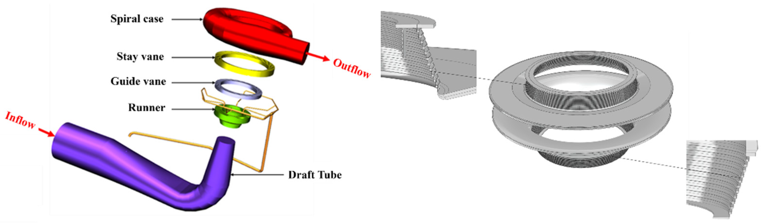
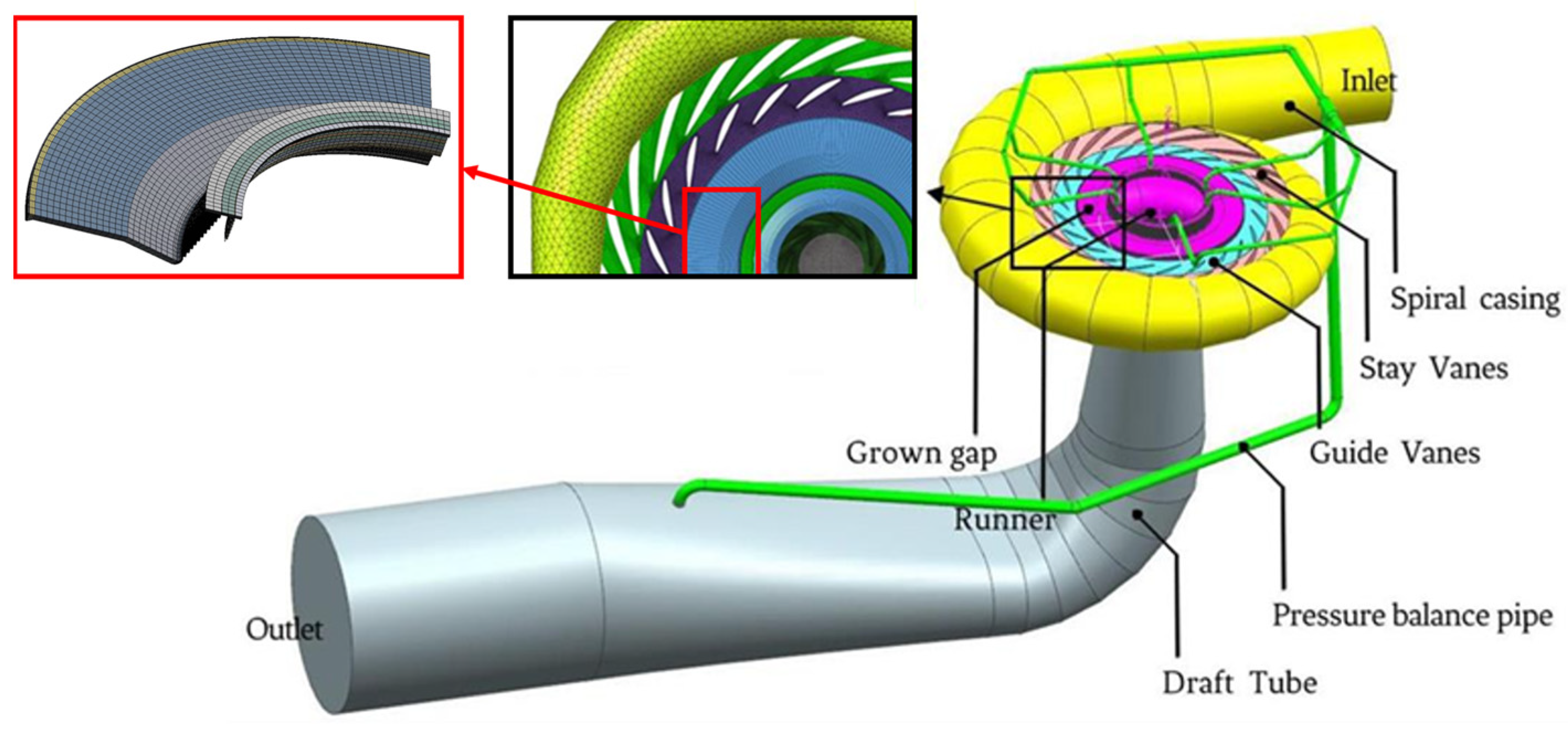
3. Geometric Model and Numerical Schemes

3.1. Variable-Speed Pump-Turbine Model and Parameters

The three-dimensional solid model of the entire flow passage components of a variable-speed pump-turbine is shown in Figure 1; the main parameters of the flow passage are provided in Table 1. And the figure on the right shows the model of the gaps on the crown and band of the runner, with a seal gap size of 1.1 mm.

3.2. Numerical Setup and Boundary Conditions

In the calculations, we used the multiple reference frame model, with the runner domain set as the rotating domain and the other domains as the stationary domain. We applied a rotor–stator-type interface for the rotor–stator interfaces with a pitch angle of 360° and the general grid interface (GGI) for the interfaces between the stationary domains. No-slip conditions were applied to all walls. The model’s inlet was specified as the total pressure inlet, with the outlet set as the mass flow outlet. The time steps for Case1, Case2, and Case3 were 0.00074 s, 0.00079 s, and 0.0073 s. Additionally, we determined the initial flow field for transient simulation using the results from the steady-state simulation, with convergence criteria set to 10−5 for both the continuity and momentum equations.

3.3. Grid Generation

The computational domain of the variable-speed pump-turbine was meshed by Ansys workbench, wherein the hexahedral elements were used for the stay vanes, guide vanes, runner, gap, and draft tube, and tetrahedral elements were employed for the spiral casing. Additionally, the pressure balance pipe utilized a hybrid grid composed of tetrahedral and hexahedral elements. A hybrid grid division approach, combining hexahedral and tetrahedral grids, was employed across the entire fluid domain to ensure computational precision and streamline computing operations. A total of five groups of grids were generated, and we found that when the number of elements exceeds 4.4 × 10⁶, the variation in power and discharge is less than 1%; thus, the model with 4.4 × 10⁶ elements was selected as the final mesh, as shown in Figure 2.
In addition, the numerical method is verified by the experimental results, and the error between the power and discharge is 1.5% and 1.7%, respectively, which confirms the reliability of the numerical method.

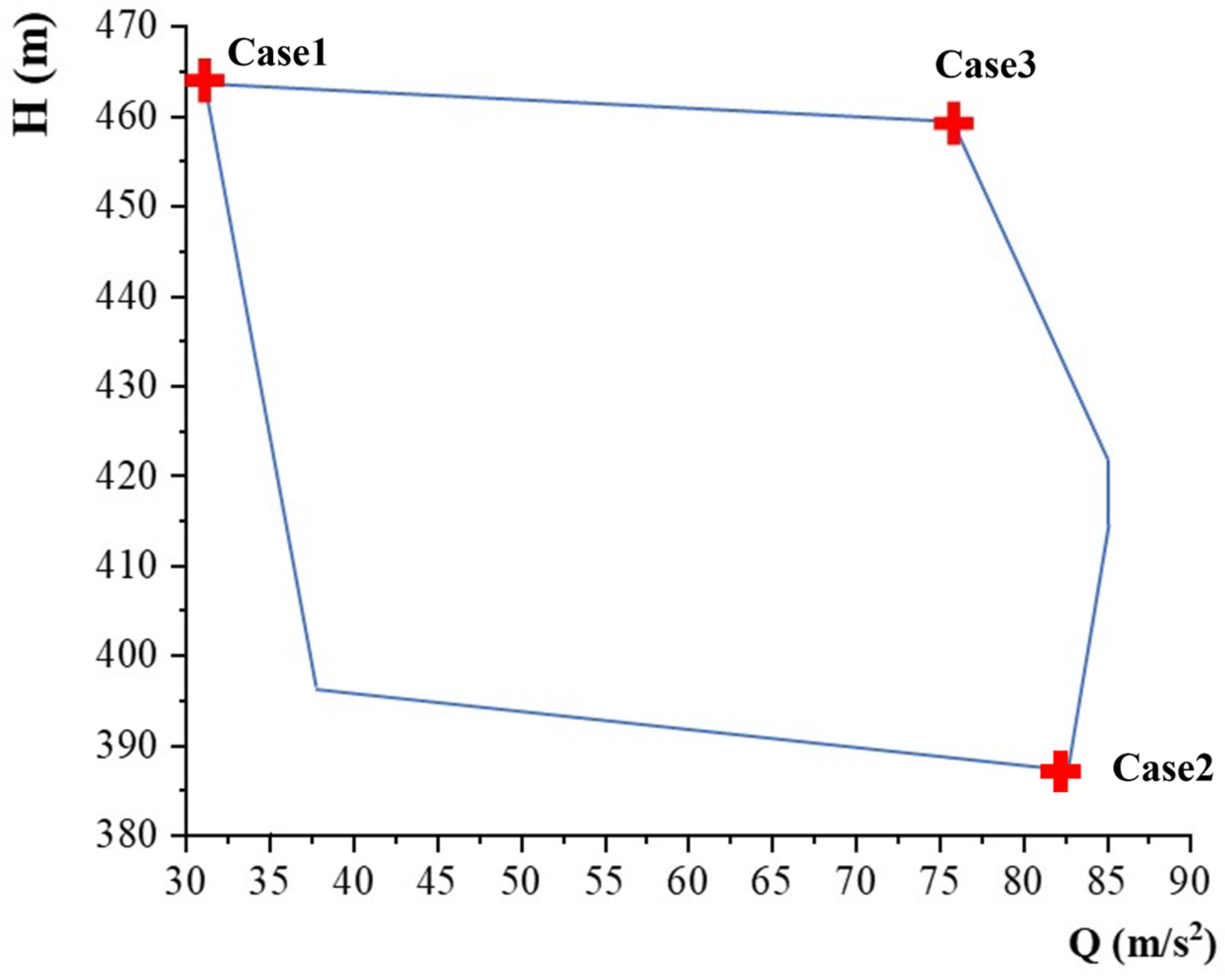
3.4. Calculated Operating Conditions

In this study, three operating points were chosen for analysis: the minimum head with maximum flow rate (referred to as Case1), the maximum head with minimum flow rate (referred to as Case2), and the maximum rotational speed (referred to as Case3) under pump modes, as shown in Figure 3. The guide vane openings for the three operating points are 27°, 8.4°, and 21.19°, and the rotational speeds are 421.09 rpm, 447.49 rpm, and 456.5 rpm, as shown in Table 2. Case1 is the most susceptible point for cavitation to occur, as well as the point where the unit’s pressure pulsations are unstable, and the maximum head of Case2 indicates that the guide vane opening is at its minimum, causing the flow to be more turbulent and the stability of the unit to be compromised.

4. Results and Discussion

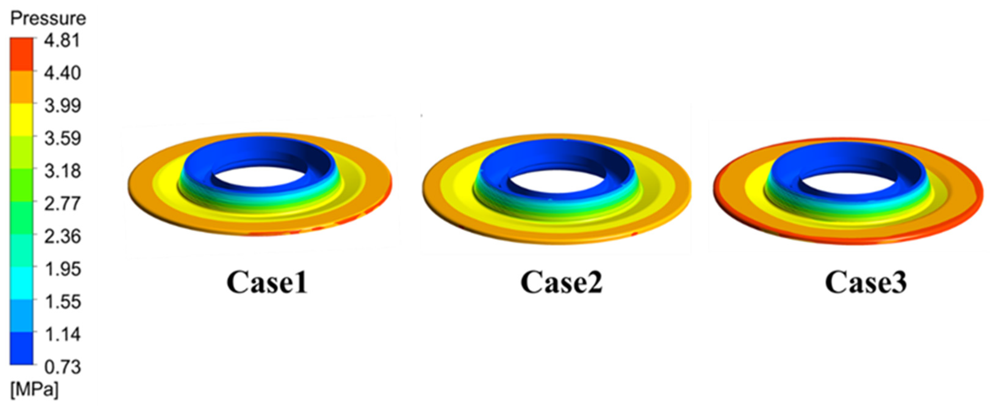
4.1. Pressure Distribution of Internal Flow Field in Variable-Speed Pump-Turbine under Pump Modes

As shown in Figure 4, under three operating conditions, the inlet of the crown gap is in the high-pressure zone and the outlet is in the low-pressure zone. With an increase in rotational speed, the inlet pressure gradually increases. However, it can be observed that the pressure gradient of the crown gap is relatively smooth, and the distribution is quite uniform. In Case2, the inlet pressure at the band gap decreases. Through analysis, it is found that this may be related to the head, and the pressure at this location is the lowest in the circumferential pressure distribution at the same radius. Additionally, with the increase in speed, the low-pressure zone of the band gap gradually increases, and the distribution becomes more uniform, as shown in Figure 5.
The pressure calculation results show that the pressure distribution within the gap is almost the same at different speeds. The pressure values at the inlet and outlet change with the speed variation, and the pressure gradient distribution within the gap channel is relatively uniform. The maximum pressure distribution is at the inlet of the crown gap, while the minimum pressure distribution is at the outlet. From the inlet to the outlet of the gap, the pressure decreases continuously along the flow direction, indicating the conversion of liquid pressure into kinetic energy. This also demonstrates the effectiveness of the labyrinth seal in reducing liquid pressure.
As shown in Figure 6, the variation in the pressure distribution in the ZX plane of the variable-speed pump-turbine exhibits a striking similarity across three different speeds. However, upon close comparative analysis, it is evident that at a speed of 456.5 rpm, the high-pressure area in front of the runner entrance is larger than the sealing structure at other operating conditions, while the low-pressure area behind the runner exit is also larger than in other conditions. Overall, as the speed increases, the area of low pressure at the runner exit gradually increases, and the high-pressure area at the runner inlet also increases. This indicates that under pump operation, at lower speeds, the average main flow pressure is higher than at higher speeds. Therefore, reducing the speed can effectively reduce leakage flow, decrease volumetric losses, allow more high-pressure fluid to enter the runner and perform work, and impact the pressure distribution upstream and downstream.
In order to analyze the pressure distribution in the crown gap and band gap, the pressure distribution in the crown gap is shown in Figure 7 and the pressure distribution in the band gap is shown in Figure 8. It can be observed that at the inlet of the crown gap at a speed of 447.56 rpm, there exists a low-pressure area. This is due to the presence of flow losses at this location, which disturbs the surrounding flow field, thereby reducing the pressure in this area. A comparative analysis of the inlet and outlet pressure distributions of the crown at different speeds shows that the pressure drop in the crown gap varies consistently. Similarly, with increasing speed, the pressure is higher on the high-pressure side and lower on the low-pressure side. However, the pressure drop variation in the band gap is similar to that in the crown gap. By reducing the speed, the pressure gradient at the inlet and outlet of the band gap can be effectively reduced, thereby improving the internal flow characteristics of the turbine.

4.2. Internal Flow Velocity Distribution of a Variable-Speed Pump-Turbine under Pump Mode

As shown in Figure 9, the velocity distributions in the ZX plane of the variable-speed pump-turbine under three different operating conditions are presented. A comparison of the velocity distributions at different speeds shows that there is minimal variation in the velocity distribution from the spiral casing to the straight conical section in the draft tube. However, in the elbow and diffuser section of the draft tube, under low-speed conditions, the area of the low-velocity flow is significantly larger compared to that of high-speed conditions. This indicates that at low speeds, the average flow velocity in the draft tube decreases.
The function of the draft tube, in addition to directing the turbine outlet flow downstream and extracting potential energy when the turbine outlet is higher than the downstream hydraulic level, also involves recovering some of the kinetic energy of the turbine outlet flow. The lower the outlet kinetic energy of the draft tube, the higher the recovery efficiency. Therefore, under pumping conditions, reducing the speed can enhance the recovery efficiency of the draft tube by decreasing the outlet kinetic energy, thus improving the hydraulic efficiency of the turbine unit.
The flow field in the gap between the crown and the band of the runner is in a strong turbulent state, with a complex and variable flow pattern. In order to study the influence of turbulent fluctuations on the stability of the turbine, the magnitude of turbulent kinetic energy, which is composed of velocity fluctuations, can be used to characterize the degree of turbulence in the flow field.
The turbulent kinetic energy distribution in the ZX plane inside the crown gap structure is shown in Figure 10. It can be observed that the turbulent energy is higher in the circumferential groove of the labyrinth seal, especially in the left half of the groove. This indicates intensified turbulent fluctuations in this area, leading to the deterioration of the flow field, causing energy dissipation in the hydraulic flow, and consequently reducing the leak flow rate and velocity, thus slowing down the leakage flow. Additionally, the turbulent kinetic energy increases with increasing rotational speed. From Figure 11, it can be seen that the rotational speed does not have a significant impact on the turbulent kinetic energy in the circumferential groove of the band gap under the pumping conditions of the variable-speed pump-turbine. Additionally, the turbulent kinetic energy of the labyrinth seal in the band gap does not show a notable difference across the three operating conditions.
The velocity streamline of the crown gap is shown in Figure 12. It can be observed that the speed from the entrance to the exit of the gap decreases. The flow velocity at the entrance of the gap is relatively high, while the exit flow velocity is low. This is because when a hydraulic flows through the labyrinth gap, it passes through many right-angled turns, increasing flow resistance, lowering the flow velocity, and increasing hydraulic loss. The dissipation cannot restore pressure energy, further increasing the energy loss of the fluid.
The velocity streamline map of the band gap of the sealing structure is shown in Figure 13. It can be seen that with increasing rotational speed, the inlet flow velocity and the velocity inside the labyrinth seal also increase. However, there is no significant difference in the exit flow velocity, and it also follows a process of decreasing flow velocity. As the rotational speed increases, it is evident that the fluid inside the crown labyrinth seal significantly increases, and it can be clearly seen that at higher rotational speeds, the flow velocity at the entrance of the labyrinth seal is greater, with more turbulent streamlines. As the rotational speed increases, there is also a clear increasing trend in the exit flow velocity, but the distribution of the streamlines remains similar.

4.3. Discussion

This study finds that the rotational speed significantly affects the pressure distribution, velocity distribution, and turbulent kinetic energy distribution inside the crown and band labyrinth seal gaps. However, the complex mechanism of the flow should be further studied.
(1)
With higher rotational speed, the area of the high-pressure region before the runner inlet is significantly larger than in other operating conditions. Similarly, the area of the low-pressure region after the runner outlet is also larger than in other operating conditions. In general, as the rotational speed increases, the low-pressure area at the runner outlet gradually increases, and the high-pressure area at the runner inlet also increases. This indicates that under pump operating conditions, at lower rotational speeds, the average main stream pressure is higher than at higher speeds. Consequently, reducing the rotational speed can effectively reduce the leakage flow and decrease the volumetric losses, allowing more high-pressure fluid to enter the runner to perform work, thereby affecting the pressure distribution upstream and downstream.
(2)
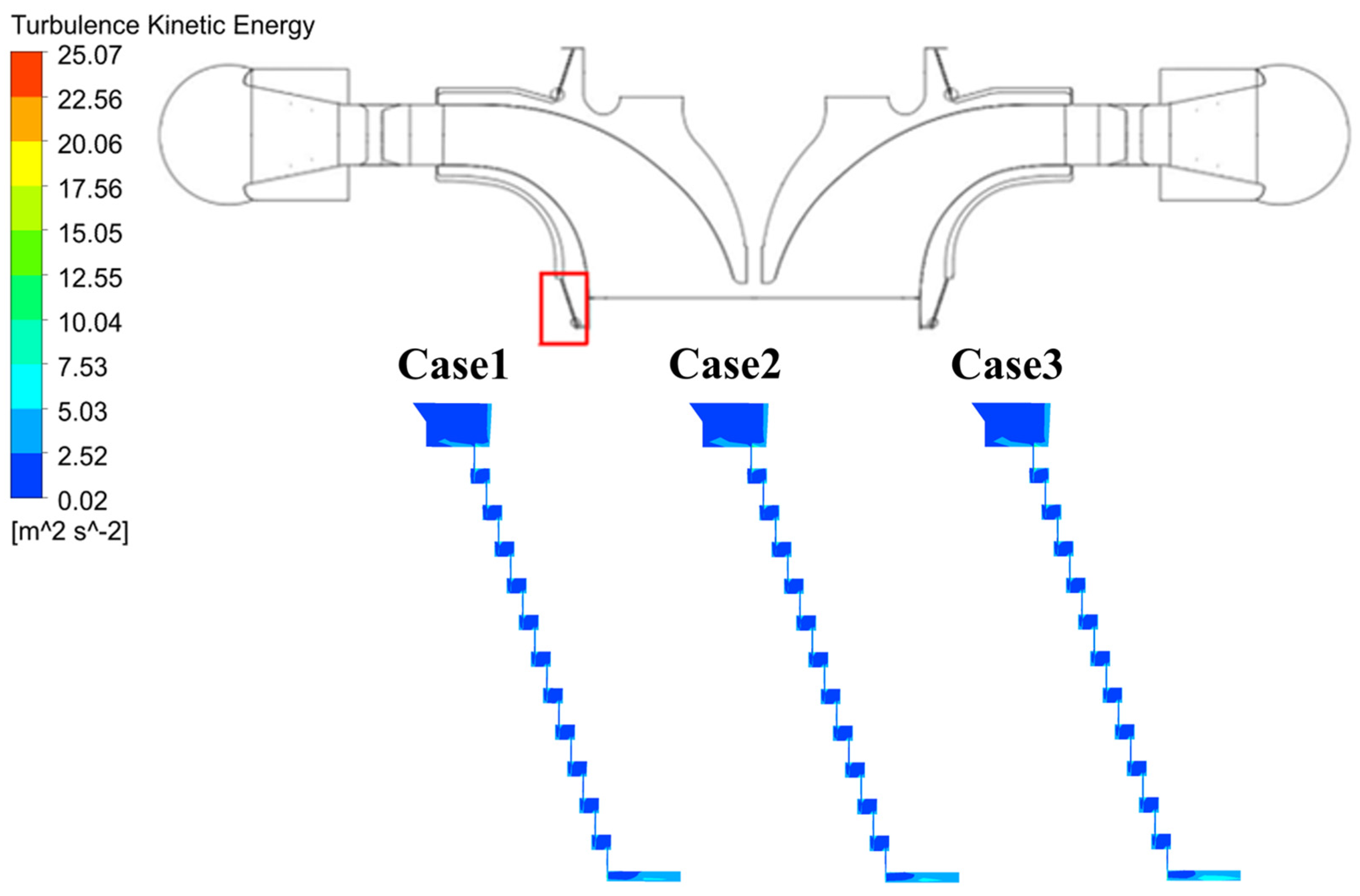
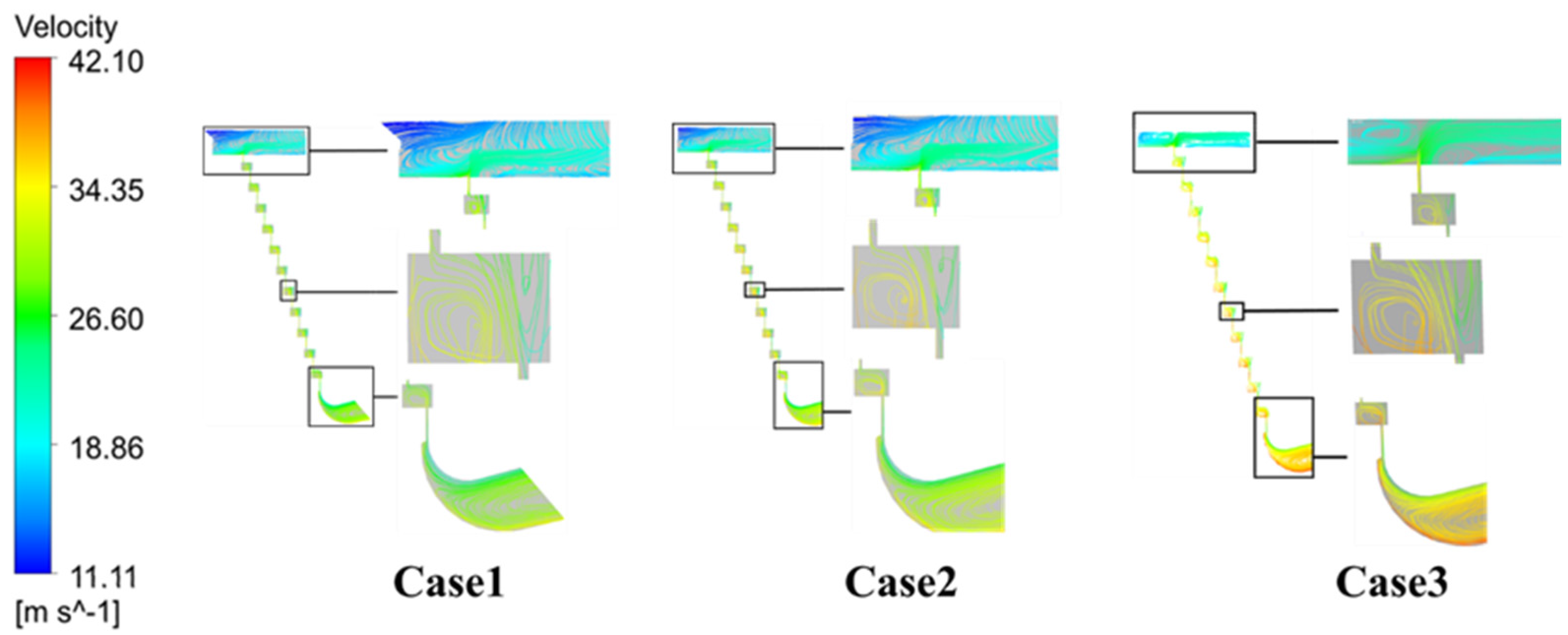
Under pump operating conditions, with the increase in the rotational speed of the variable-speed pump-turbine unit, the changes in pressure and velocity at the crown gap are significant. Rotational speed primarily affects the internal flow field of the crown gap, with the most notable changes occurring at the inlet and outlet of the crown gap in terms of pressure and velocity. There is a significant pressure drop trend inside the gap, and as the rotational speed increases, the pressure and velocity also increase. However, as the rotational speed increases, the pressure and velocity distribution within the band gap remains almost the same. Under the condition of maximum speed, there is an observed increase in the pressure and velocity distribution at the inlet of the band gap.
(3)
In the three operating conditions, it can be observed that at the highest head and minimum flow rate conditions, there are phenomena that do not conform to the increase in flow velocity and pressure at the inlet and outlet of the crown gap with increasing rotational speed. At the inlet and outlet of the lower crown labyrinth seal gap, there is a low-pressure area, and the area of low-flow velocity is significantly larger compared to the higher speed conditions. This indicates that the pressure within the labyrinth seal gap and the flow velocity within the passages are also related to the head, especially in the condition of maximum head, where this particular change becomes more apparent.

5. Conclusions

This article investigates the variable-speed pump-turbine under three typical pump modes through CFD numerical simulation. The main conclusions drawn from the study are as follows:
(1)
The rotational speed significantly affects the pressure distribution, velocity distribution, and turbulent kinetic energy distribution inside the crown and band labyrinth seal gaps.
(2)
With higher rotational speed, the area of the high-pressure region before the runner inlet is significantly larger than in other operating conditions, and reducing the rotational speed can effectively reduce the leakage flow and decrease the volumetric losses, allowing more high-pressure fluid to enter the runner to perform work, thereby affecting the pressure distribution upstream and downstream.
(3)
With the increase in the rotational speed, the changes in pressure and velocity at the crown gap are significant. Rotational speed primarily affects the internal flow field of the crown gap, with the most notable changes occurring at the inlet and outlet of the crown gap in terms of pressure and velocity.
(4)
The pressure within the labyrinth seal gap and the flow velocity within the passages are also related to the head, especially in the condition of maximum head, where this particular change becomes more apparent.

Author Contributions

Data curation, writing—original draft, investigation, formal analysis, S.Y.; methodology, project administration, Z.W.; software validation, S.L.; conceptualization, funding acquisition, writing—review and editing, L.W. All authors have read and agreed to the published version of the manuscript.

Funding

This research was funded by the Science and Technology Project of State Grid Xinyuan Group Co., Ltd. SGXYKJ-2022-066.

Data Availability Statement

The original contributions presented in the study are included in the article, further inquiries can be directed to the corresponding author.

Conflicts of Interest

The authors Lei Wang, Shuang Yu and Sainan Li were employed by the company Hebei Fengning Pumped Storage Energy Co., Ltd. The remaining authors declare that the research was conducted in the absence of any commercial or financial relationships that could be construed as a potential conflict of interest. The company Hebei Fengning Pumped Storage Energy Co., Ltd. in affiliation and Xinyuan Group Co., Ltd. in funding had no role in the design of the study; in the collection, analyses, or interpretation of data; in the writing of the manuscript, or in the decision to publish the results.

References

  1. Zhang, F.; Fang, M.; Pan, J.; Tao, R.; Zhu, D.; Liu, W.; Xiao, R. Guide vane profile optimization of pump-turbine for grid connection performance improvement. Energy 2023, 274, 127369. [Google Scholar] [CrossRef]
  2. Damdoum, A.; Slama-Belkhodja, I.; Pietrzak-David, M.; Debbou, M. Low voltage ride-through strategies for doubly fed induction machine pumped storage system under grid faults. Renew. Energy 2016, 95, 248–262. [Google Scholar] [CrossRef]
  3. Fu, X.; Li, D.; Song, Y.; Wang, H.; Yang, J.; Wei, X. Pressure fluctuations during the pump power-trip of a low-head pump-turbine with the co-closing of guide vane and ball valve. J. Energy Storage 2023, 59, 106470. [Google Scholar] [CrossRef]
  4. Sarasúa, J.I.; Pérez-Díaz, J.I.; Wilhelmi, J.R.; Sánchez-Fernández, J.Á.J.E.C. Dynamic response and governor tuning of a long penstock pumped-storage hydropower plant equipped with a pump-turbine and a doubly fed induction generator. Energy Convers. Manag. 2015, 106, 151–164. [Google Scholar] [CrossRef]
  5. Pannatier, Y.; Kawkabani, B.; Nicolet, C.; Simond, J.J.; Schwery, A.; Allenbach, P. Investigation of Control Strategies for Variable-Speed Pump-Turbine Units by Using a Simplified Model of the Converters. IEEE Trans. Ind. Electron. 2010, 57, 3039–3049. [Google Scholar] [CrossRef]
  6. Shang, L.; Cao, J.; Wang, Z.; Liu, X. Hydraulic Characterization of Variable-Speed Pump Turbine under Typical Pumping Modes. Processes 2023, 11, 2903. [Google Scholar] [CrossRef]
  7. Shang, L.; Cao, J.; Wang, L.; Yu, S.; Ding, S.; Wei, Z.; Wang, Z.; Liu, X. Analysis of Flow and Runner Dynamic Response Characteristics under Pump Conditions of Variable-Speed Pump Turbine. J. Mar. Sci. Eng. 2023, 11, 1493. [Google Scholar] [CrossRef]
  8. Wanfeng, H.; Zhengwei, W.; Honggang, F. Grid synchronization of variable speed pump-turbine units in turbine mode. Renew. Energy 2021, 173, 625–638. [Google Scholar] [CrossRef]
  9. Guo, W.; Xu, X. Sliding mode control of regulating system of pumped storage power station considering nonlinear pump-turbine characteristics. J. Energy Storage 2022, 52, 105071. [Google Scholar] [CrossRef]
  10. He, L.; Zhou, L.; Ahn, S.-H.; Wang, Z.; Nakahara, Y.; Kurosawa, S. Evaluation of gap influence on the dynamic response behavior of pump-turbine runner. Eng. Comput. 2019, 36, 491–508. [Google Scholar] [CrossRef]
  11. Hao, Y.; Tan, L. Symmetrical and unsymmetrical tip clearances on cavitation performance and radial force of a mixed flow pump as turbine at pump mode. Renew. Energy 2018, 127, 368–376. [Google Scholar] [CrossRef]
  12. Koirala, R.; Zhu, B.; Neopane, H. Effect of Guide Vane Clearance Gap on Francis Turbine Performance. Energies 2016, 9, 275. [Google Scholar] [CrossRef]
  13. Kim, T.S.; Cha, K.S. Comparative analysis of the influence of labyrinth seal configuration on leakage behavior. J. Mech. Sci. Technol. 2009, 23, 2830–2838. [Google Scholar] [CrossRef]
  14. Guo, Q.; Zhou, L.; Wang, Z. Numerical evaluation of the clearance geometries effect on the flow field and performance of a hydrofoil. Renew. Energy 2016, 99, 390–397. [Google Scholar] [CrossRef]
  15. Kan, K.; Li, H.; Chen, H.; Xu, H.; Gong, Y.; Li, T.; Shen, L. Effects of Clearance and Operating Conditions on Tip Leakage Vortex-Induced Energy Loss in an Axial-Flow Pump Using Entropy Production Method. J. Fluids Eng. 2023, 145, 031201. [Google Scholar] [CrossRef]
  16. Liu, Y.; Tan, L. Tip clearance on pressure fluctuation intensity and vortex characteristic of a mixed flow pump as turbine at pump mode. Renew. Energy 2018, 129, 606–615. [Google Scholar] [CrossRef]
  17. Han, Y.; Tang, T.; Xiang, G.; Jia, H. A Fluid–Solid–Heat Coupling Analysis for Water-Lubricated Rubber Stern Bearing Considering the Deflection of Propeller Shaft. Appl. Sci. 2021, 11, 1170. [Google Scholar] [CrossRef]
  18. Kan, K.; Xu, Y.; Li, Z.; Xu, H.; Chen, H.; Zi, D.; Gao, Q.; Shen, L. Numerical study of instability mechanism in the air-core vortex formation process. Eng. Appl. Comput. Fluid Mech. 2023, 17, 2156926. [Google Scholar] [CrossRef]
  19. Song, X.; Luo, Y.; Wang, Z. Numerical prediction of the influence of free surface vortex air-entrainment on pump unit performance. Ocean Eng. 2022, 256, 111503. [Google Scholar] [CrossRef]
  20. Song, X.; Wang, Z. Numerical prediction of the effect of free surface vortex air-entrainment on sediment erosion in a pump. Proc. Inst. Mech. Eng. Part A J. Power Energy 2022, 236, 1297–1308. [Google Scholar] [CrossRef]
  21. Zhang, L.; Wang, X.; Wu, P.; Huang, B.; Wu, D. Optimization of a centrifugal pump to improve hydraulic efficiency and reduce hydro-induced vibration. Energy 2023, 268, 126677. [Google Scholar] [CrossRef]
  22. Luo, Y.; Wang, Z.; Liu, X.; Xiao, Y.; Chen, C.; Wang, H.; Yan, J. Numerical prediction of pressure pulsation for a low head bidirectional tidal bulb turbine. Energy 2015, 89, 730–738. [Google Scholar] [CrossRef]
  23. Qian, Z.; Wang, F.; Guo, Z.; Lu, J. Performance evaluation of an axial-flow pump with adjustable guide vanes in turbine mode. Renew. Energy 2016, 99, 1146–1152. [Google Scholar] [CrossRef]
Figure 1. Three-dimensional model for entire fluid passages.
Processes 12 01424 g001
Figure 2. Variable-speed pump-turbine CFD domain and mesh.
Processes 12 01424 g002
Figure 3. The stable operating zone of the unit.
Processes 12 01424 g003
Figure 4. Pressure distribution of crown gap outside wall.
Processes 12 01424 g004
Figure 5. Pressure distribution of lower band gap outside wall.
Processes 12 01424 g005
Figure 6. Pressure distribution of ZX plane.
Processes 12 01424 g006
Figure 7. Pressure distribution of crown gap inlet and outlet.
Processes 12 01424 g007
Figure 8. Pressure distribution of lower band gap inlet and outlet.
Processes 12 01424 g008
Figure 9. Velocity distribution of ZX plane.
Processes 12 01424 g009
Figure 10. Turbulent Kinetic Energy nephogram of crown gap on ZX plane.
Processes 12 01424 g010
Figure 11. Turbulent Kinetic Energy nephogram of lower band gap on ZX plane.
Processes 12 01424 g011
Figure 12. The velocity streamline of the crown gap.
Processes 12 01424 g012
Figure 13. The velocity streamline of the band gap.
Processes 12 01424 g013
Table 1. Variable-speed pump-turbine specification parameters under pumping conditions.
Parameter NameSymbolsValues
Impeller exit diameterD2 (mm)2162.6
Impeller entrance diameterD1 (mm)408.4
Number of impeller bladesnIM (−)9
Number of stay/guide vanesnSV/nGV (−)22/22
Spiral casing exit diameterDOUT (mm)2350
Draft tube entrance diameterDIN (mm)2197
Rated headHR (m)430
Rated dischargeQR (m3)79.16
Rated rotation speednR (r/min)428.6
Table 2. Calculated working conditions.
Working ConditionsGuide Vane Opening α (◦)Speed (rpm)
Case1 (HMin, QMax)8.4421.09
Case2 (HMax, QMin)27447.49
Case3 (Maximum rotational speed)21.19456.5
Disclaimer/Publisher’s Note: The statements, opinions and data contained in all publications are solely those of the individual author(s) and contributor(s) and not of MDPI and/or the editor(s). MDPI and/or the editor(s) disclaim responsibility for any injury to people or property resulting from any ideas, methods, instructions or products referred to in the content.

