Article

Thermal Power Calculation of Interior Permanent Magnet Eddy Current Heater Using Analytical Method

by
Honglei Lu
,
Ling Zhang
and
Wenpeng Hong
*
School of Energy and Power Engineering, Northeast Electric Power University, Jilin 132000, China
*
Author to whom correspondence should be addressed.
Processes 2024, 12(7), 1457; https://doi.org/10.3390/pr12071457
Submission received: 14 June 2024 / Revised: 4 July 2024 / Accepted: 9 July 2024 / Published: 12 July 2024
(This article belongs to the Section Energy Systems)

Abstract

:
This paper presents an interior permanent magnet eddy current heater (IPMECH) that can be driven by wind turbine, which can realize the direct conversion of wind energy to thermal energy. A power analysis method for the IPMECH is proposed. The key to this method is to consider the influence of the skin effect on the distribution of eddy currents based on Coulomb’s law, Maxwell’s equation, and the Lorentz force law. Firstly, the equivalent magnetic circuit model is established, and the mathematical analytical expressions of air gap magnetic flux density (MFD), torque and thermal power of the IPMECH are derived. Then, the air gap MFD, torque and thermal power of the IPMECH are calculated, respectively. Finally, the analytical method (AM) is verified by the finite element method (FEM) and experiments. The results show that the proposed AM is sufficient to calculate the air gap MFD and thermal power of the IPMECH. The AM provides a quick and easy way to optimize and design an IPMECH.

1. Introduction

In response to the issue of climate change, China announced at the 75th General Assembly of the United Nations in 2020 that it aims to peak carbon dioxide emissions by 2030 and strive to achieve carbon neutrality by 2060 [1]. In terms of clean and renewable energy, China is rich in wind energy resources and has the prospect of large-scale development and utilization, and wind power generation has developed rapidly in the past decade [2,3,4,5]. As of the end of 2023, China’s installed wind power capacity has reached 441.34 GW, accounting for 43.23% of the global total installed capacity [6]. Although the total installed capacity of wind power has increased year by year, many provinces have experienced serious wind curtailment [7,8,9]. China’s installed wind power capacity is 2.53 times that of the United States, and in the same year, China’s wind power generation capacity was only 1.87 times that of the United States [10]. There are three main reasons for wind curtailment: (1) Wind energy is intermittent and unstable [11,12,13]. To ensure the safe operation of the power grid, large-scale grid connection of wind power is restricted [14,15,16]. (2) China’s wind power generation is mostly concentrated in the Three-Northern region, where the demand for electricity load is relatively low and it is difficult to consume wind power generation [14,17]. (3) In the Three-Northern region, most of the electricity demand is delivered to the grid by coal-fired combined heat and power (CHP) plants [18]. In winter, in order to meet the heating needs of buildings (hot water for the customers through the centralized heating system), CHP plants must operate almost at full capacity, and by design, the CHP plants must generate electricity while heating [19]. In winter, with good wind resources, the large heat demand leads to a potential oversupply of electricity from CHP plants, resulting in a large amount of wind curtailment [20,21].
With the rapid development of the national economy and the improvement of people’s living standards, the demand for heating and domestic hot water is increasing, and the demand for low-grade heat energy accounts for more than half. The rapid development of urbanization in China has led to a continuous increase in the area of central heating buildings in northern cities and towns. By the end of 2022, the heating area of buildings in Northern China is 23.8 billion m2, including 16.7 billion m2 for urban heating and 7.1 billion m2 for rural heating [22]. In the non-electric field, especially in the field of building heating, the development level of renewable energy in China is significantly lagging. At present, China is facing the double pressure of a heating shortage and clean energy heating substitution. In order to alleviate the problem of “wind power curtailment and power limitation” and solve the demand for low-grade thermal energy of users, wind power heating is widely used [8,18,23,24]. Wind energy is first converted into electricity, which is transmitted to users through the grid, and then converted into thermal energy. China has conducted wind power heating pilot projects in Inner Mongolia, Jilin, and other places, utilizing wind power for heating and heat storage to achieve heating for residents. However, the economic efficiency of electric heating boilers is poor and does not comply with the scientific energy utilization principle of “temperature matching and cascade utilization” [25].
Permanent magnetic eddy current wind heating has the advantages of high energy utilization, low requirements for wind quality, strong adaptability to wind conditions, and easy implementation [26,27]. It has become a new direction of wind energy utilization in the world, which has attracted widespread attention at home and abroad [28,29]. Their research can be divided into the following components: (1) Establishment of the heater model. H. Du [30,31] established a mathematical model of hysteresis loss, eddy current loss, and copper loss based on the basic electromagnetic theory. Shukang C [32] established the mathematical model for hysteresis, eddy current, and short-circuit power of flameless heater. J. Chu [33] established a mathematical theoretical model and a thermal circuit model for the thermal power of the heater based on electromagnetic fields and empirical formulas. (2) Optimization and operation characteristics of heaters. T. Tudorache [34] analyzed the effects of stator wall thickness and material, magnetic pole pairs, air gap length, and permanent magnet geometric parameters on the thermal power of a permanent magnet eddy current heater (PMECH). I. Dirba [35] found that the stator body should be made of materials with high conductivity, and the permanent magnet should be made of NdFeB material. V. Fireeanu [36] analyzed the relationship between the maximum power of PMECH and the number of pole pairs and rotational speed and determined the optimal value of the stator wall thickness. A. Khanjari [37,38] studied their effects on magnetic flux and torque through experimentation and numerical simulations by changing the number of magnetic poles and magnets, magnetization area, and gaps in different directions of permanent magnets. Research shows that the energy efficiency of PMECH exceeds 95% at different rotational speeds. X. H. Liu [26] experimentally verified the effects of rotational speed and the gap between the turntable and the heating plate on the temperature rise of the heating plate, obtaining an empirical formula for the torque. I. Sobor [39] used a PMECH for experimental research and obtained a semi-empirical formula for the thermal power, which is proportional to 1.5 squares of rotational speed, and found that the heating efficiency exceeds 90%. (3) Effect of temperature on the heater. L. Chen [40] proposed a thermal power-temperature coupling calculation method to determine the actual thermal power and temperature of the heater and verified the correctness of the analytical results through experimentation. O. Nebi [41] considered the influence of temperature on material physical properties and magnetic nonlinearity and studied the input and output characteristics of the heater. (4) Other structural forms of heater. T. Tudorache [42] proposed an outer rotor PMECH and optimized the number of magnetic poles. H. Du [43] proposed a dual-rotor PMECH, established a mathematical model to estimate the eddy current loss of the heater, and verified the validity and correctness of the model. T. Tudorache [44,45] proposed an electric-thermal wind generator that can convert rotating mechanical energy into electrical and thermal energy. (5) Research on wind magnetic eddy current heating system. O. G. P. Kirichenko [46] proposed suggestions for the design of wind magnetic eddy current heating systems and provided system design instructions. T. Tudorache [47] determined the preliminary size of the wind turbine, analyzed the heat transfer characteristics of the heater, and the dynamic response of the wind system.
The above scholars focused on the effect of different parameters on the thermal power and efficiency of PMECH, but few analytical formulas were given on the influence of structural parameters on the thermal power, and the rotors of PMECH all adopted the surface-mount type, which has the risk of demagnetization of the permanent magnets [34,42]. The interior permanent magnet rotor structure has an obvious saliency effect and reluctance torque, which is easier for achieving high power density and high torque density. The permanent magnet is embedded inside the rotor core, which is not easy to demagnetize and has high reliability [48,49]. Based on the above analysis, this article focuses on the structural design of an IPMECH and the establishment of thermal power analytical models. The main contributions of this article are summarized as follows:
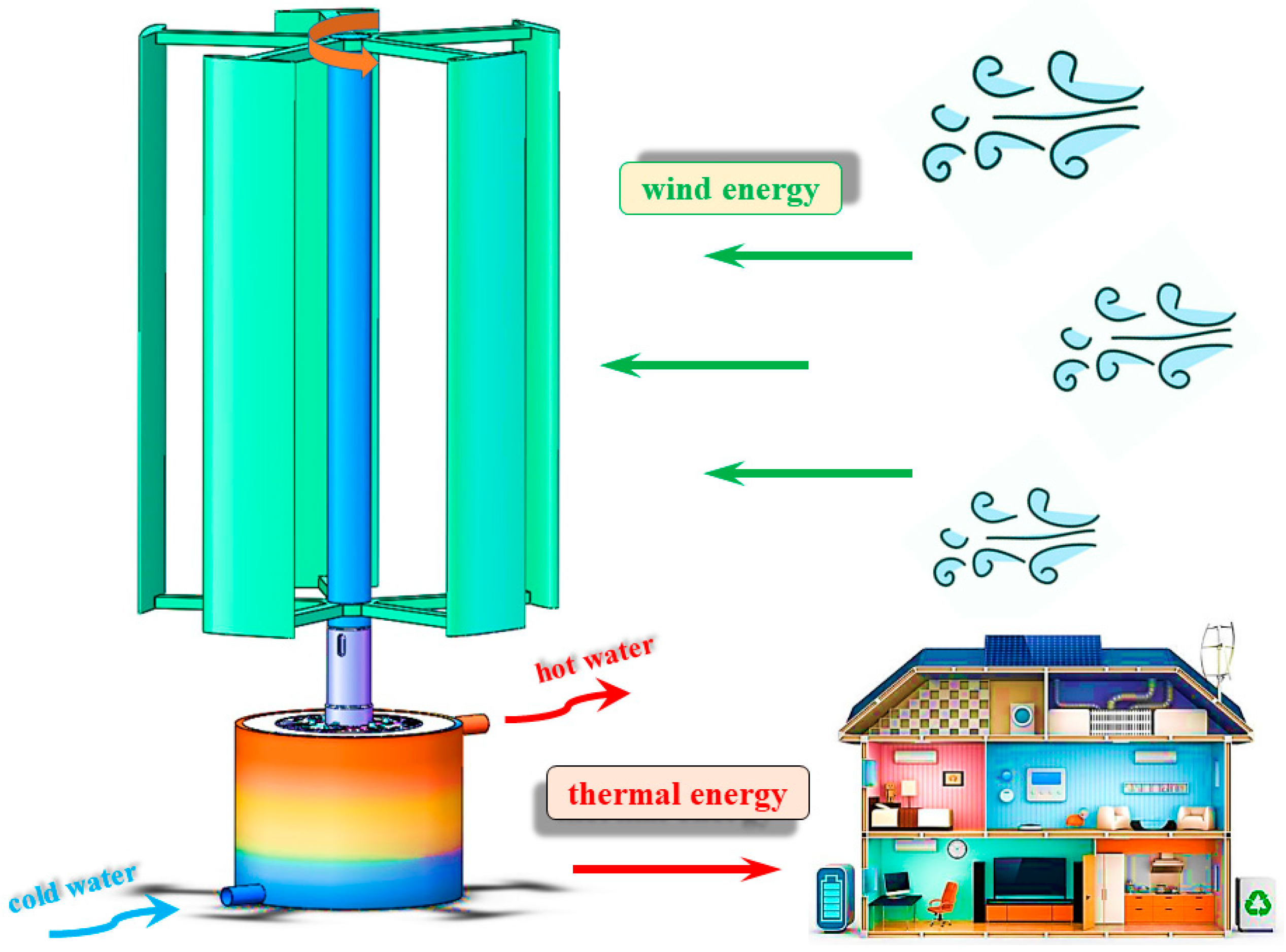
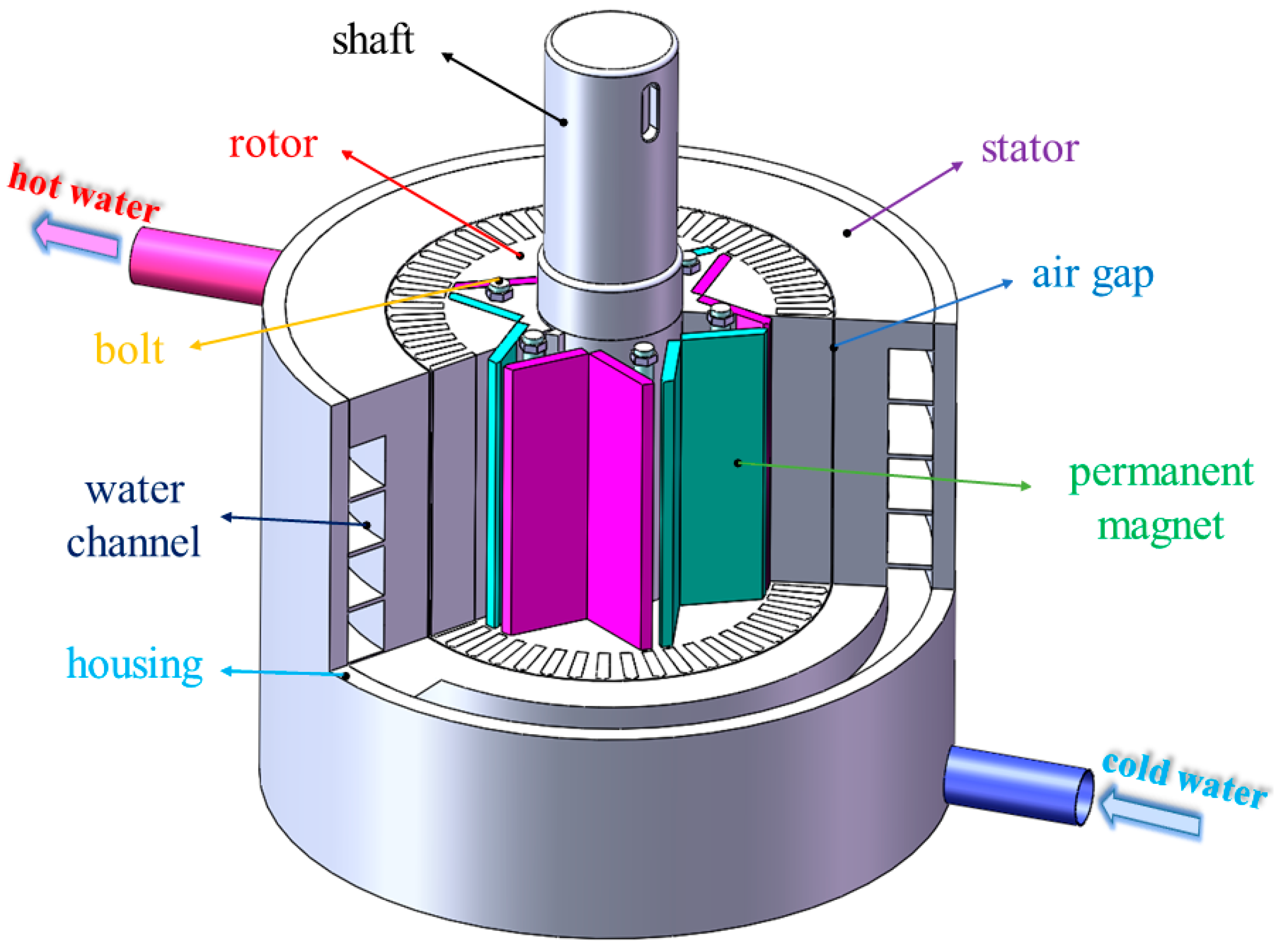
  • The structural design characteristics and working principle of PMECH are analyzed and an IPMECH is designed.
  • Based on the structural characteristics of the IPMECH and the basic electromagnetic field theories such as Coulomb’s law, Maxwell’s equation, and the Lorentz force law, an equivalent magnetic circuit model and a mathematical analytical model for the thermal power of the IPMECH are established.
  • The validity and accuracy of the analytical model are verified by the FEM and experiments, which provides a theoretical basis for further structural design and optimization.

2. Structure and Mathematical Model of IPMECH

2.1. Structure and Working Mechanism of IPMECH

PMECH is an energy conversion device used for heating fluids, which can utilize other energy sources such as wind and water, and this energy is efficiently converted into thermal energy through the dragging of the heater by the prime mover. It can be used as heating equipment to heat large buildings, individual buildings, and homes. The permanent magnet eddy current wind heating system with a wind turbine as the prime mover is shown in Figure 1.
The IPMECH is shown in Figure 2. The heater is mainly composed of a main shaft, stator, rotor permanent magnet, and housing, and adopts an inner-rotor outer-stator structure. Six V-shaped permanent magnets are embedded in the rotor, and rectangular parallel magnetized permanent magnets are adopted. To improve the dynamic stability of the heater, the rotor is fixed by bolts and poured with cast aluminum. There is a circumferential spiral pipeline inside the stator, with the fluid inlet and outlet reserved, connected to the external circulation pipeline, and made of magnetic core material. The wind turbine drives the main shaft of the heater to rotate and drives the permanent magnet installed on the main shaft to establish a rotating magnetic field. The rotating magnetic field is hinged with the stator through the air gap, which generates electromotive force on the stator. By using the eddy current thermal effect, wind energy is efficiently converted into thermal energy, and thermal energy is provided to the outside through the fluid medium.

2.2. Electromagnetic Field Analysis of IPMECH

Combined with the structural characteristics of the heater, based on the theory of electromagnetic fields, the basic assumptions and simplifications of the heater are made, and the equations of the electromagnetic field are established. Figure 3 shows the simplified model of an IPMECH. The maximum and minimum angles of the permanent magnet are α and β, respectively, and the thickness is h and the width is w. The thickness of the flux barrier b and c are b and c, respectively, R1 and R2 are the rotor shaft radius and rotor outer diameter, and R3 and R4 are the stator inner diameter and outer diameter, respectively. The solution model is divided into the rotor core region (r), the air gap region (ag), the stator region (s) and the external region (e).
The basic assumptions and simplifications are as follows:
  • Simplify the 3D model to a 2D model by ignoring the end effect of the heater.
  • The displacement current in the stator and air gap is ignored; that is, the normal current density on the stator surface is a constant of 0.
  • All components of the electromagnetic field are continuously differentiable near the analysis point, and the stator, rotor, and permanent magnet materials are isotropic. The conductivity, permeability, and permittivity are all constants.
  • The electromagnetic field is considered an approximately stable alternating electric field, and only the fundamental wave is considered while the harmonics are ignored in the analysis.
  • All quantities must have the same frequency (angular frequency) but can have different phase angles.
Maxwell’s equation and the constitutive equations are as follows [50]:
× H = J
B = 0
× E = B t
D = 0
D = ε E
B = μ H
J = σ E
where H is the magnetic field intensity, J is the current density, B is the MFD, E is the electric field, D is the electric displacement, ε is the permittivity, μ is the permeability, and σ is the conductivity.
The quantity that the eddy current field actually solves for is A, the magnetic vector potential. It is given by Equation (8). To ensure the uniqueness of the magnetic vector potential, the Coulomb gauge Equation (9) is introduced.
B = × A
A = 0
Substituting Equations (6) and (8) into Equation (1), the result becomes the following:
2 A = μ J
The second-order partial differential electromagnetic field equations for each region of the heater solution model can be derived from Equation (10). Given the current density in the rotor core region (r), the air gap region (ag), and the external region (e) current density is 0, Equation (10) can be simplified as Equation (11). The stator region (s) electromagnetic field equations, Equation (12), can be derived from Equations (3) and (8).
2 A r = 2 A ag = 2 A e = 0
E = A t = ω A θ
where ω is the angular frequency and θ is the phase angle of the solution point.

2.3. Solution and Analysis of Air Gap MFD of IPMECH

The air gap MFD generated by the magnet can be divided into three parts: the magnetic flux Φ pm flowing through the permanent magnet and the leakage magnetic flux Φ b and Φ c flowing through the flux barrier b and c. The magnetic lines of flux of the heater mainly flows through the permanent magnet, flux barrier, rotor yoke, air gap, and stator yoke. Due to the yoke part of the heater, there is no obvious magnetic saturation phenomenon, thus the yoke part of the reluctance of the smaller can be ignored. Therefore, the equivalent magnetic circuit model in Figure 4 is established. Φ m is the equivalent magnetic flux source of the permanent magnet. The reluctance at the permanent magnet and the flux barrier b and c are R pm , R b , and R c , respectively. Φ ag /2 is the air gap magnetic flux flowing through the air gap, and the corresponding reluctance is 2 R ag . The other parameters in Figure 4 can be derived from Equations (13)–(17).
Φ m = B r w L
R pm = h μ pm w L
R ag = l ag μ air α r ag L
Φ b = B sl b L
Φ c = B sl c L
where B r is the remanence of the permanent magnet, L is the effective axial length of the heater, μ pm and μ a i r are the permanent magnet permeability and the air permeability, respectively. l ag is the air gap length, r ag is the radius of the air gap, B sl is the saturation level of the B-H curve of the rotor core. The B-H curve is shown in Figure 5.
The heater air gap MFD distribution function is Equation (18) [51,52]. Based on the equivalent magnetic circuit model in Figure 4, using Kirchhoff’s law, Equation (19) is derived. Equations (20) and (21) can be used to calculate the air gap flux and the MFD amplitude, respectively.
B ag = 0 0 mod ( θ , 2 γ ) < γ α 2 mod ( θ , 2 γ ) γ α 2 · 2 B ag-pm α β γ α 2 mod ( θ , 2 γ ) < γ β 2 B ag-pm γ β 2 mod ( θ , 2 γ ) < γ + β 2 B ag-pm mod ( θ , 2 γ ) γ α 2 · 2 B ag-pm α β γ + β 2 mod ( θ , 2 γ ) < γ + α 2 0 γ + α 2 mod ( θ , 2 γ ) < 3 γ α 2 mod ( θ , 2 γ ) γ α 2 · 2 B ag-pm α β 3 γ α 2 mod ( θ , 2 γ ) < 3 γ β 2 B ag-pm 3 γ β 2 mod ( θ , 2 γ ) < 3 γ + β 2 mod ( θ , 2 γ ) γ α 2 · 2 B ag-pm α β B ag-pm 3 γ + β 2 mod ( θ , 2 γ ) < 3 γ + α 2 0 3 γ + α 2 mod ( θ , 2 γ ) < 2 γ
Φ m = Φ pm + Φ b + Φ c + Φ ag 2 R pm Φ pm = R b Φ b = R c Φ c = R ag Φ ag
Φ ag = 2 ( Φ m Φ b Φ c ) R pm R pm + R ag
B ag-pm = Φ ag r ag α L
where B ag is the MFD of the air gap, B ag-pm is the magnitude of the air gap MFD, and Φ ag is the magnetic flux of the air gap. γ is equal to π p ( p is the number of pole pairs).
The magnetic flux flowing through the air gap flows into the stator region of the heater, so the air-gap magnetic flux is the same as the stator magnetic flux. Equation (22) is derived from Equations (13)–(18), (20) and (21) and is used to solve the MFD of the stator.
B s = 0 0 mod ( θ , 2 γ ) < γ α 2 mod ( θ , 2 γ ) γ α 2 2 Φ ag α ( α β ) r s L γ α 2 mod ( θ , 2 γ ) < γ β 2 Φ ag α r s L γ β 2 mod ( θ , 2 γ ) < γ + β 2 Φ ag α r s L mod ( θ , 2 γ ) γ α 2 2 Φ ag α ( α β ) r s L γ + β 2 mod ( θ , 2 γ ) < γ + α 2 0 γ + α 2 mod ( θ , 2 γ ) < 3 γ α 2 mod ( θ , 2 γ ) γ α 2 2 Φ ag α ( α β ) r s L 3 γ α 2 mod ( θ , 2 γ ) < 3 γ β 2 Φ ag α r s L 3 γ β 2 mod ( θ , 2 γ ) < 3 γ + β 2 mod ( θ , 2 γ ) γ α 2 2 Φ ag α ( α β ) r s L Φ ag α r s L 3 γ + β 2 mod ( θ , 2 γ ) < 3 γ + α 2 0 3 γ + α 2 mod ( θ , 2 γ ) < 2 γ
where B s is the MFD of the stator and r s is the radius of the stator.

2.4. Thermal Power and Eddy Current Distribution of the Heater Stator

Since the influence of the end effect is ignored in this paper, the stator conductor can be regarded as having an axial length L of infinity, and only the eddy current distribution and thermal power in the stator conductor under the action of the permanent magnet poles are analyzed. Take a piece of permanent magnet mapping the area of the stator conductor on the length and width of m 1 and n 1 , respectively, as the object of study, and with the center of the micro-element as the origin, establish a coordinate system so that i , j , and k are the x-, y-, and z-axis unit vectors, respectively. The magnetic induction strength of this micro-elementary region is as follows:
B = B s k
Since the thickness of the stator is much smaller than its radius, it can be assumed that the curvature of the stator is infinite. The stator cylinder model is transformed into a rectangular model, assuming that R is the average radius of the stator. For the convenience of analysis, it is assumed that the rotor is stationary, the stator moves in the opposite velocity vector, and the velocity vector of the stator conductor can be written as:
v = v i = ω R i
When a stator conductor moves to the right in an MFD B with speed v in a direction perpendicular to the magnetic field, an induced electric field v × B in a downward direction will be generated inside the conductor. The charges in the conductor undergo directional motion due to the Lorentz force, causing the positive charges to move to the bottom of the conductor and the negative charges to move to the top of the conductor, forming an upward-directed Coulomb electric field E . The integrated electric field in the stator conductor is obtained through Equation (25).
E = E + v × B
The charge distribution in the stator conductor micro-elements is shown in Figure 6. The surface charge densities ρ y , ρ y + at the edges of the stator conductor micro-elements ( y = ± m 1 / 2 , a plane parallel to the x-z plane) are, respectively:
ρ y = ε 0 v B ρ y + = + ε 0 v B
where ε 0 is the vacuum permittivity.
To solve the Coulomb field strength of the surface charge density, a double integral calculation is required. In order to simplify the calculation process, define ρ M S and ρ N S as the uniformly distributed line charge density parallel to the z-axis and passing through the points ( x 1 , m 1 / 2 ) and ( x 1 , m 1 / 2 ) on an infinitely long straight line, and ρ M S and ρ N S can be derived from Equation (27). The charge densities ρ M S and ρ N S and the Coulomb field strengths E y + and E y at any point S(x, y) of the conductor are given by Equation (27). The charge densities ρ M S and ρ N S and Coulomb field strengths E y + and E y at any point S(x, y) of the conductor are given by Equation (28).
ρ M S = + ε 0 v B Δ x ρ N S = ε 0 v B Δ x
E y + = v B 2 π n 1 2 n 1 2 ( x x 1 ) ( x x 1 ) 2 + ( y m 1 / 2 ) 2 i + ( y m 1 / 2 ) ( x x 1 ) 2 + ( y m 1 / 2 ) 2 j d x E y = v B 2 π n 1 2 n 1 2 ( x x 1 ) ( x x 1 ) 2 + ( y + m 1 / 2 ) 2 i + ( y + m 1 / 2 ) ( x x 1 ) 2 + ( y + m 1 / 2 ) 2 j d x
The synthetic Coulomb field strength E at the point S(x, y) is the E y + and E y vector sum, i.e.,
E = E y + + E y
Since ρ M S and ρ N S are uniformly distributed linear charge densities along the z-axis, the Coulomb field strength has a component of 0 in the z-direction, and the components in the x- and y-directions can be determined by Equations (30) and (31).
E x = v B 4 π ln ( 2 x + n 1 ) 2 + ( 2 y m 1 ) 2 · ( 2 x n 1 ) 2 + ( 2 y + m 1 ) 2 ( 2 x n 1 ) 2 + ( 2 y m 1 ) 2 · ( 2 x + n 1 ) 2 + ( 2 y + m 1 ) 2
E y = v B 2 π arctan 2 x + n 1 2 y m 1 arctan 2 x n 1 2 y m 1 arctan 2 x + n 1 2 y + m 1 + arctan 2 x n 1 2 y + m 1
The simultaneous Equations (7), (25), (30) and (31) can determine the current density J in the stator conductor micro-element, and the components in the x and y directions are as follows:
J = σ ( E + v × B )
J x = σ E x
J y = σ ( E y + v × B )
The Lorentz force exerted in the stator conductor in the magnetic pole mapping region can be derived from the following equation:
F = V J × B d V
Due to the interaction of forces, the force on the rotor in the x direction, i.e., the electromagnetic force, is as follows:
F x = V J y × B d V
Under the action of multiple pairs of magnetic poles, the components of the electromagnetic force in the y-direction cancel each other out, and only the electromagnetic force in the x-direction exists in the stator conductor, and the eddy current loss, i.e., the thermal power, generated in the stator conductor is as follows:
P = F x · v = v V σ ( E y + v × B ) × B d V

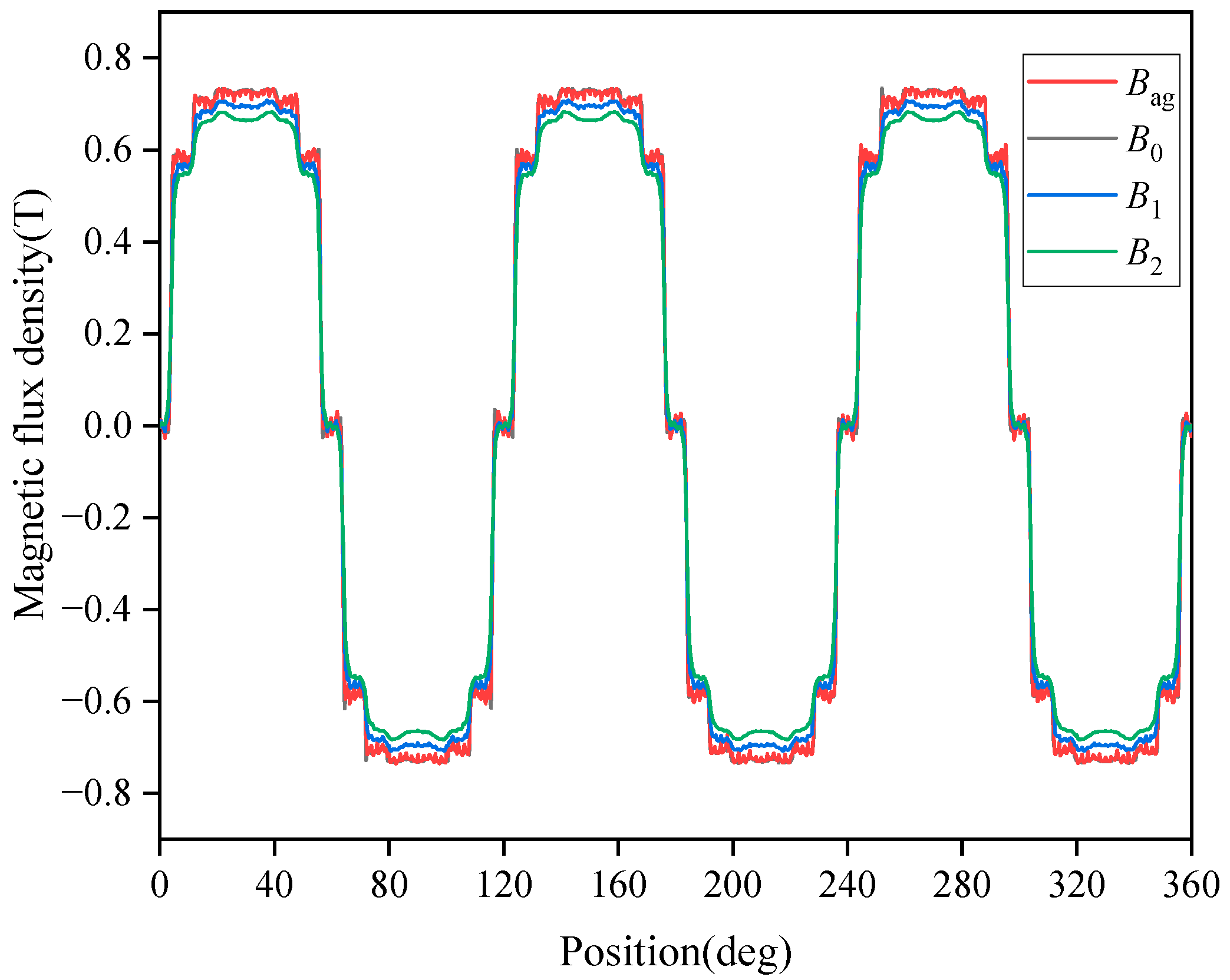
2.5. Thermal Power and Eddy Current Distribution Considering Skin Effect

During the operation of the heater, there is an armature reaction in the stator of the heater similar to that of a motor. The MFD generated by the eddy currents in the stator will change the original magnetic field. The MFD B generated by the eddy currents in the stator is in the opposite direction of the original MFD B , so that the net MFD B n after the superposition is smaller than the original MFD B . Therefore, the effect of induced magnetic flux needs to be considered in the derivation and calculation of the mathematical model of eddy current losses and thermal power, and the magnitude of the electromagnetic force on the stator conductor is revised to the following equation:
F x = V J × B n d V
For the purpose of calculating the net MFD B n , B is defined as the ratio of the induced MFD to the original MFD, i.e., B = B B , and the net magnetic induction can be calculated by Equation (39).
B n = B e B
The induced MFD B is mainly generated by the eddy current I y in the y-direction, and according to Ampere’s law, the eddy currents I y can be obtained by Equation (41).
B = μ 0 I y 2 l ag
I y = 2 n 1 2 n 1 2 0 R 4 R 3 2 J y d x d z
where μ 0 is the vacuum permeability and I y is the component of the eddy current in the y-direction.
Equation (41) is only adapted to the uniform distribution of the eddy current density inside the conductor, without considering the uneven characteristics of the current distribution caused by the skin effect. From the surface of the conductor to the current density, decreases to the surface current density of 1 / e at a distance d s is the skin depth.
d s = 2 σ ω f μ 0 μ r = 60 σ μ 0 μ r π p n B sl
where ω f is the electromagnetic field alternating angular velocity, μ r is the relative permeability of stator material, and n is the rotational speed of the rotor.
According to the two-dimensional traveling wave propagation theory in electromagnetic fields, the current density inside the stator can be calculated from Equation (43).
J = J m e z / d s cos ( ω f t y γ π R 3 + R 4 2 z d s )
where J m is the current density of the conductor surface.
Even if the thickness of the stator conductor is less than the skin depth, the non-uniform distribution of current density in the z-direction should be considered. Introducing the equivalent skin depth d s of the stator conductor, assuming that the current density within this thickness is J y and the current density distribution is uniform, Equations (44) and (45) can be obtained.
2 n 1 2 n 1 2 0 R 4 R 3 2 J y e z / d s d x d z = 2 n 1 2 n 1 2 0 d s J y d x d z
d s = d s ( 1 e R 4 R 3 2 d s )
From Equations (42) and (45), the equivalent skin depth is a function of rotational speed and decreases with increasing rotational speed. The modified I y can be obtained from Equation (46). Equation (47) shows the revised mathematical analytical model for the thermal power of the IPMECH.
I y = 2 n 1 2 n 1 2 0 d s / 2 J y d x d z
P = F x · v = ( R 3 + R 4 ) v 2 B n σ B n 1 / 2 n 1 / 2 m 1 / 2 m 1 / 2 1 2 π U ( x , y ) + 1 d x d y U ( x , y ) = arctan 2 x + n 1 2 y m 1 arctan 2 x n 1 2 y m 1 arctan 2 x + n 1 2 y + m 1 + arctan 2 x n 1 2 y + m 1

3. Validation by FEM

In this section, the results obtained using the AM and FEM are presented to verify the correctness of the AM. For fair comparison, the AM and FEM use the same structural and physical parameters of the heater. The detailed structural parameters of the IPMECH are shown in Table 1. The FEM is based on the commercial software Ansys Electronics Desktop 17.1, and the components are at a room temperature of 22 ℃. In addition, a Vector potential boundary of 0 weber/m is chosen for the boundary conditions. To verify the independence of grid size and time step, the variation of thermal power with different numbers of cells and time steps was tested. The results of the thermal power calculations are shown in Figure 7, and after comparison, a cell of 48,214 and a time step of 0.0005 s are chosen in this paper.

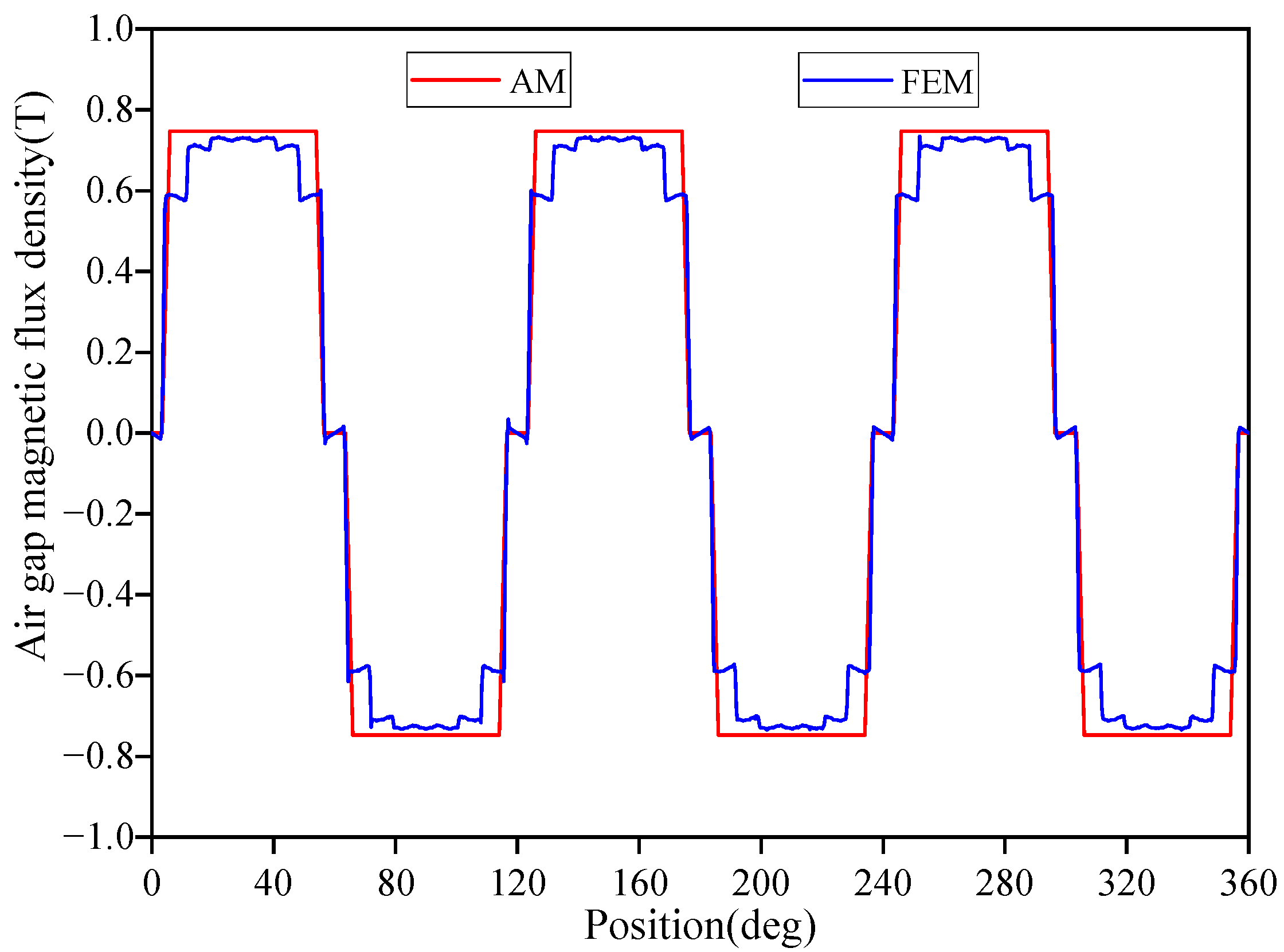
3.1. The MFD of IPMECH

Figure 8 shows the static air gap MFD of the IPMECH obtained by the FEM and the AM. From the figure, it can be seen that the air gap MFD obtained by the FEM and the AM are similar, and the amplitude differences are not significant. The amplitude of the air gap MFD obtained by the FEM is 0.734 T, while the result obtained by the AM is 0.747 T. The difference in this value is due to the fact that in the AM, it is assumed that the stator, rotor, and cast aluminum reluctance of the actuator are neglected, but in the FEM, the model reluctance is not neglected, which leads to a slight increase in the value of the AM-computed air gap MFD. In the FEM calculation, due to the effect of cast aluminum reluctance, it makes the path of the magnetic induction line shifted, resulting in the FEM calculation of the air gap MFD flat-top waveform presenting a jagged shape, and the air gap MFD waveform is slightly different from the results of the AM calculation. The AM calculates the air gap MFD amplitude with a smaller error of 1.77% compared to the FEM. The difference between the AM and the FEM is acceptable, and the AM is accurate in calculating the air gap MFD.
Figure 9 shows the characteristics of the MFD distribution at different locations of the heater, where B 0 , B 1 , and B 2 are the radial density values at different positions of the density circumference at 0, 1, and 2 mm from the inner edge of the stator, respectively. From the figure, it can be seen that the air gap MFD almost completely coincides with the MFD at 0 mm along the inner edge of the stator, verifying the rationality of Equation (22). The MFD with the increase of radial values shows a decreasing trend, with the reason being because the stator has a certain amount of reluctance, as well as with the increase of radial value, the air gap magnetic flux is the same as the stator magnetic flux, the stator curvature is not infinite, and the magnetic flux flows through the stator region area increases, resulting in the size of the MFD becoming smaller.

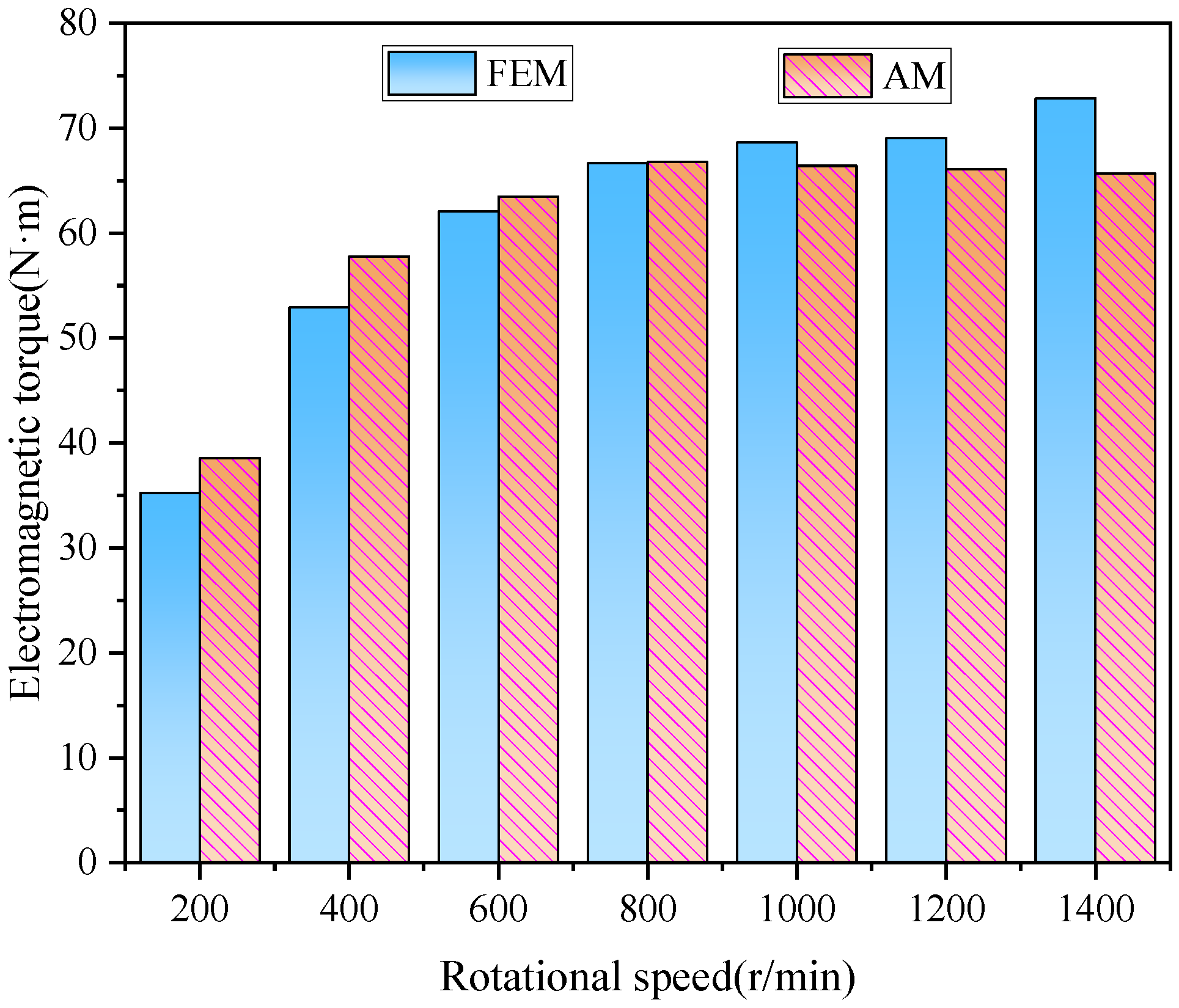
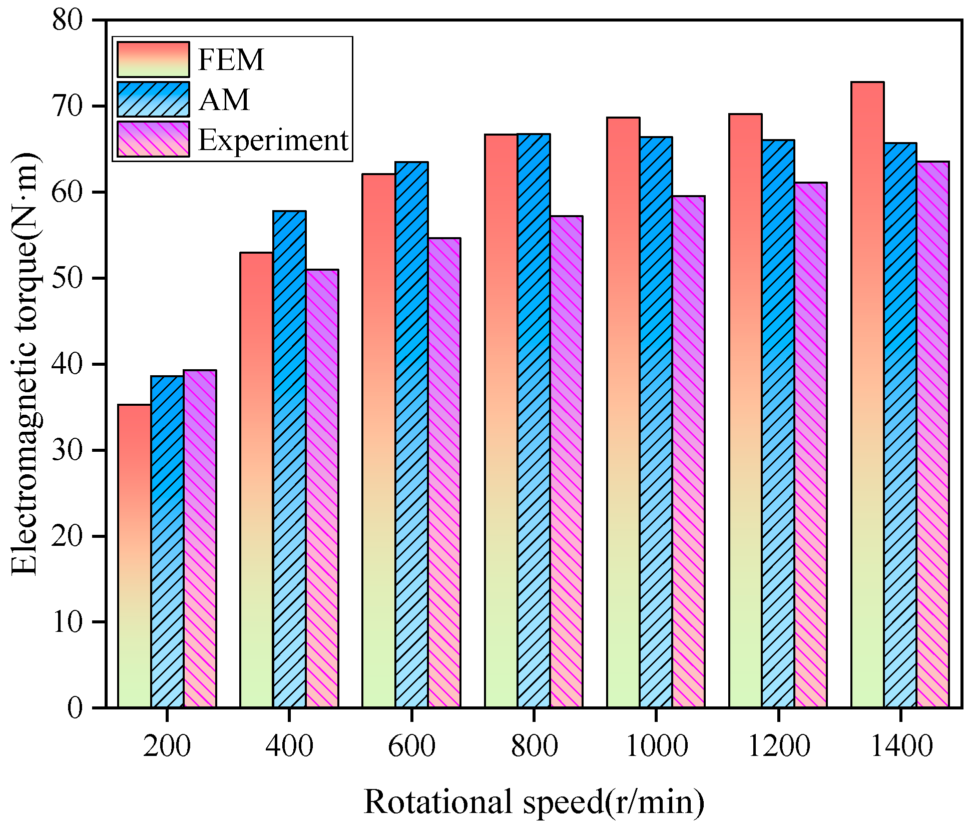
3.2. The Electromagnetic Torque of IPMECH

Figure 10 shows the comparison of electromagnetic torque between the FEM and AM at different rotational speeds. It can be seen that the results of the AM are higher than those of the FEM for rotational speeds of 800 r/min and below, while the results are the opposite for rotational speeds above 800 r/min. At rotational speeds of 200 r/min and 1400 r/min, the average electromagnetic torques are 35.25 N·m and 72.82 N·m for the FEM and 38.54 N·m and 65.66 N·m for the AM, respectively. At any rotational speed, the error between the AM and the FEM calculation results is within 10%, and the calculation results are approximate with high consistency.

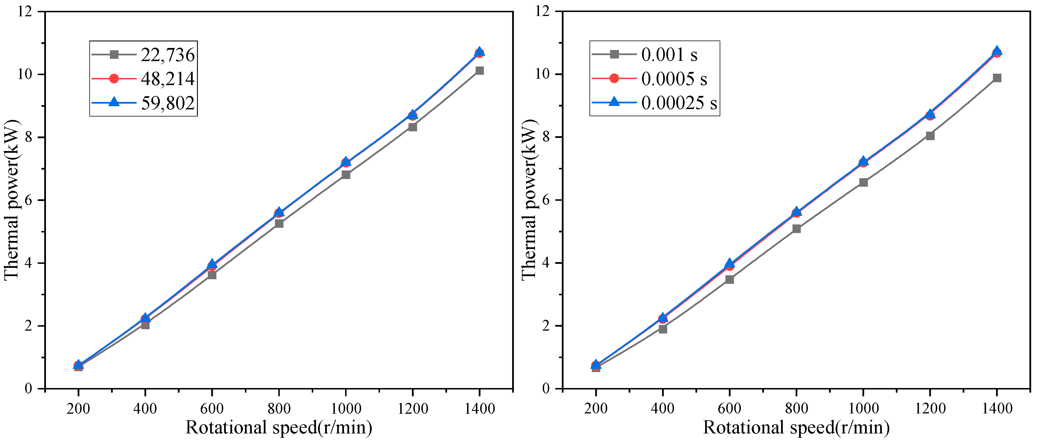
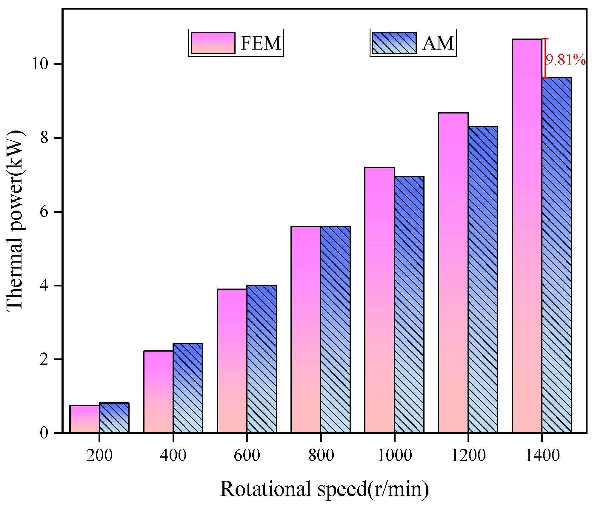
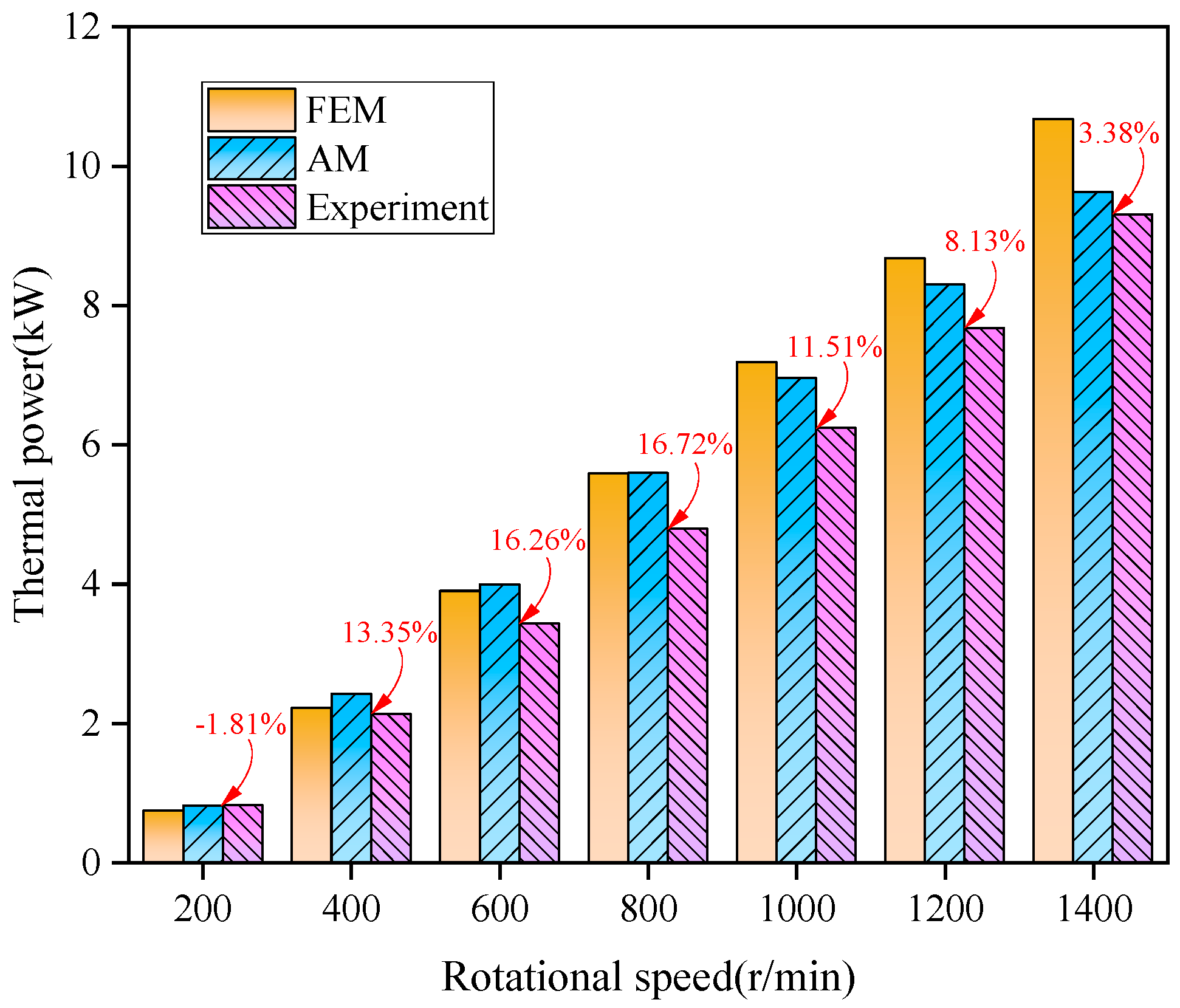
3.3. The Thermal Power of IPMECH

Figure 11 shows the FEM and AM thermal power at different rotational speeds. It can be observed that the results of the AM and FEM are consistent. When the rotational speed is below 800 r/min, the AM results are higher than the FEM results. As the rotational speed increases, the difference between the AM and FEM results gradually decreases. After the rotational speed reaches 1000 r/min, the FEM results are greater than the AM results. The maximum error between the AM and the FEM calculation results is 9.81% at 1400 r/min (red words in the figure), and at this rotational speed, the thermal power obtained by the AM and FEM are 9.63 kW and 10.68 kW, respectively. At low speeds, the calculation results of the AM are higher than those of the FEM. The main reason for this is that the internal MFD of the stator is assumed to be constant in the AM, and the stator curvature is not infinite. The MFD gradually decreases in the radial direction in the stator cylindrical model (as shown in Figure 9), and the stator rotor and cast aluminum reluctance have a certain impact on the attenuation of the MFD amplitude, resulting in the results of the AM being higher than the results of the FEM. As the rotational speed increases, the difference between the AM results and the FEM results become gradually smaller mainly because of the increase of the induced current, which makes the magnetic field strength at the rotor core reach saturation, and the core permeability decreases, the magnetic flux inside the magnetic pole mapping region decreases, and the magnetic flux outside the region increases relatively. In the process of establishing the analytical model of thermal power, the MFD outside the magnetic pole mapping region has been idealized as 0, which means that the eddy current loss generated outside the magnetic pole mapping region is not included in Equation (22). As the rotational speed increases, the neglected eddy current loss becomes larger, so the AM results are lower than the FEM results. The skin depth becomes smaller as the rotational speed increases, and the attenuation of MFD in the radial direction decreases in the FEM. The armature effect of the heater becomes stronger at higher speeds, and the influence of the stator, rotor, and cast aluminum reluctance on the heater gradually decreases. Therefore, the difference between the AM results and the FEM results becomes smaller as the rotational speed increases, and the results of the AM are smaller than the results of the FEM when the rotational speed is higher than 1000 r/min.

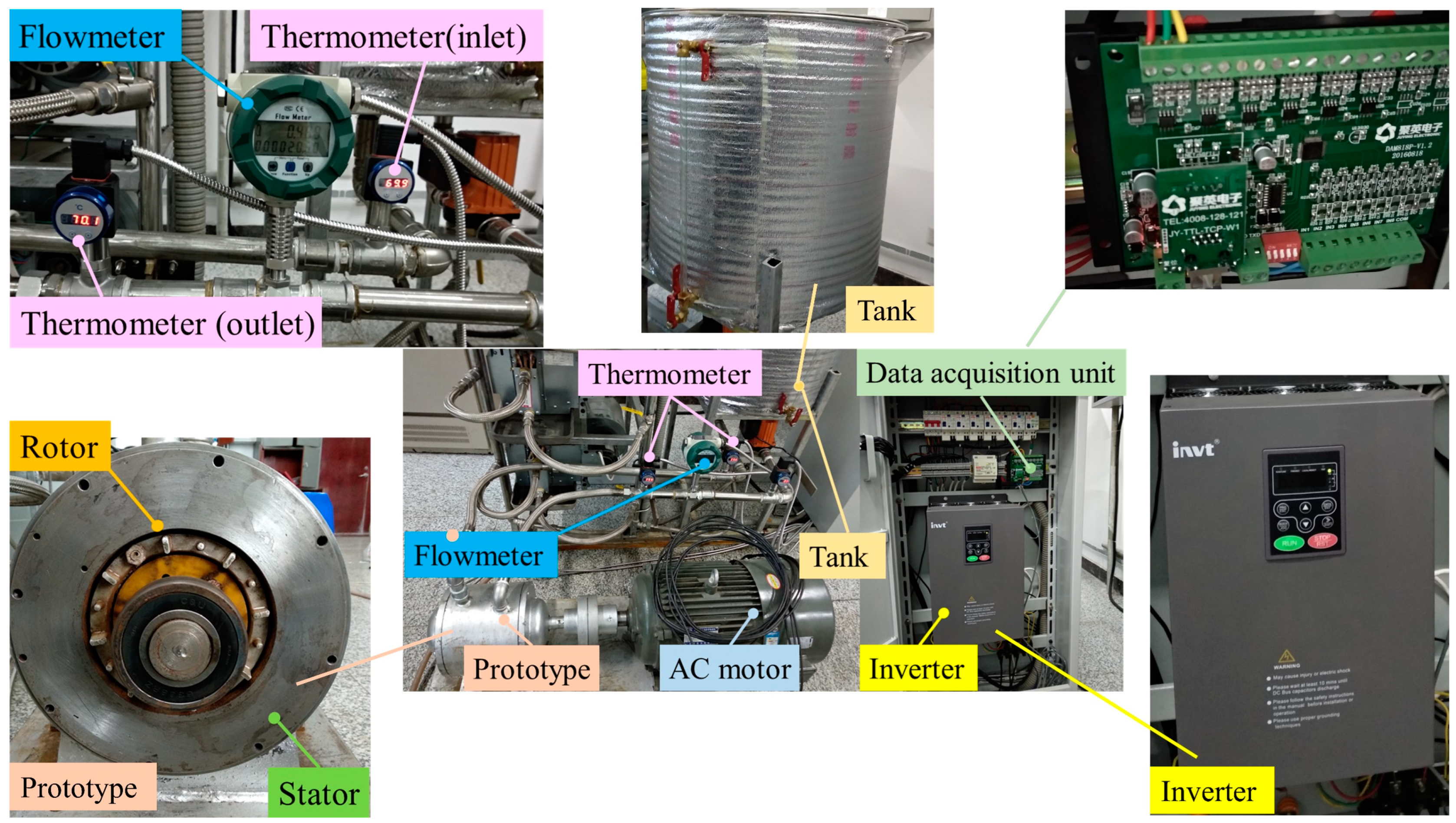
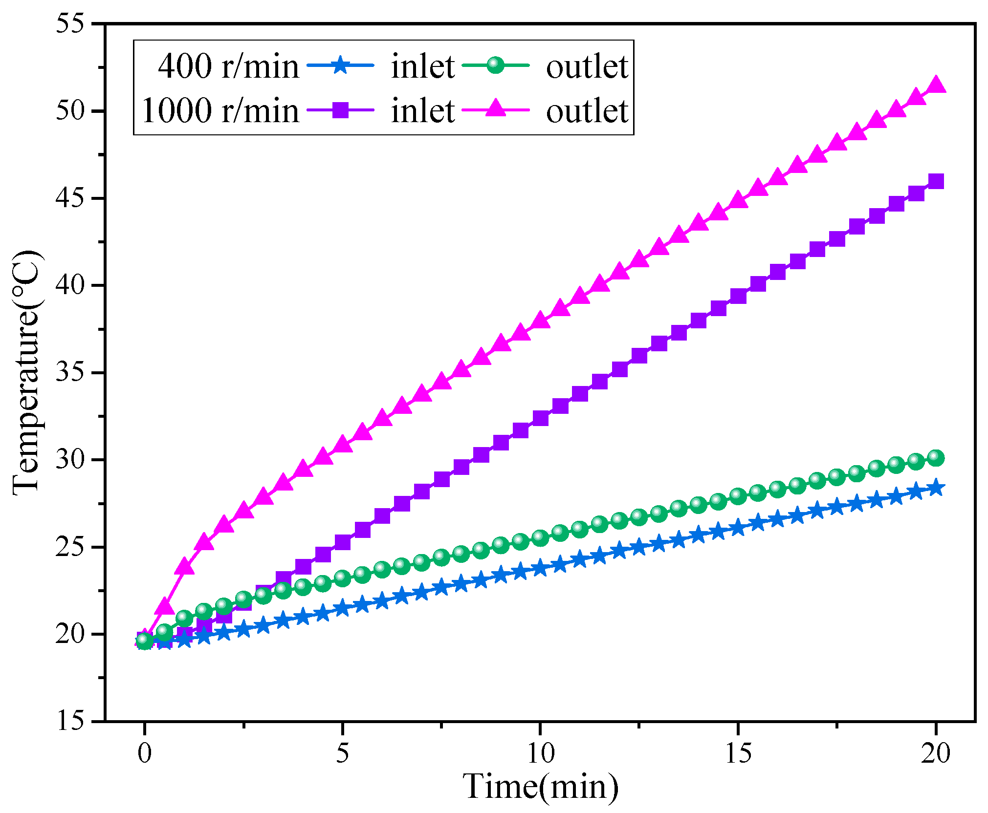
4. Experimental Validation

The IPMECH experimental platform is shown in Figure 12. A variable frequency AC motor is used to simulate the wind mechanical energy at different wind speeds, and the AC motor is controlled by an inverter and drives the prototype to rotate, allowing the prototype to operate at different speeds. In order to ensure that the temperature of the fluid flowing into the prototype is constant, the experimental platform contains a constant temperature water tank. Temperature sensors are placed at the fluid inlet and outlet pipes of the prototype, the flowmeter is at the fluid inlet, and the rotational speed and torque data of the prototype can be obtained through the inverter. All output data during the experiment are collected by a data logger and transmitted to a computer.
Figure 13 shows the temperature variation of the inlet and outlet of the IPMECH. It can be seen that the inlet and outlet temperature with time shows an upward trend; the larger the rotational speed of the inlet and outlet temperature difference is larger. The temperature difference between the inlet and outlet is basically stabilized after a period of time.
Figure 14 shows the comparison of the FEM, AM, and experimental electromagnetic torque at different speeds of the IPMECH. It can be seen that the FEM results are closer to the experimental values at speeds of 400–800 r/min, and the AM results are closer to the experimental values at speeds of 1000–1400 r/min. At a rotational speed of 600 r/min, the average electromagnetic torque derived from the FEM, AM, and experimental method are 62.06 N·m, 63.49 N·m, and 54.61 N·m, respectively. At a rotational speed of 1200 r/min, the electromagnetic torque derived from the FEM, AM, and experimental method are 69.05 N·m, 66.06 N·m, and 61.10 N·m, respectively. The AM and FEM results do not differ significantly from the experimental values.
Figure 15 shows the comparison of the FEM, AM, and experimental thermal power at different rotational speeds of the IPMECH. From the figure, it can be observed that at 200 r/min, the experimental results are higher than those of the FEM and AM, while the experimental results at 400–1400 r/min are lower than those of the FEM and AM. The reason is that the influence of end effects and mechanical losses on the heating power are not considered in the calculation process of the FEM and AM. With the increase of rotational speed, the difference between the AM and experimental method of the IPMECH thermal power shows a tendency of increasing and then decreasing. The maximum difference is 16.72% at 800 r/min (red words in the figure), and at this rotational speed, the AM and experimental results are 5.59 kW and 4.79 kW, respectively. At 200 and 1400 r/min, the differences between the AM and experimental results are −1.81% and 3.38%, respectively. By comparing the AM and experimental results, it can be concluded that the proposed analytical model is sufficient to calculate the thermal power characteristics of the IPMECH.

5. Conclusions

In this paper, an IPMECH is proposed, which can be driven by a wind turbine to achieve the direct conversion of wind energy to thermal energy. Based on the basic electromagnetic field theories such as Coulomb’s law, Maxwell’s equations, and the Lorentz force law, combined with the structural characteristics and working principles of the heater, an equivalent magnetic circuit model is established, and the mathematical analytical expressions for the air gap MFD, electromagnetic torque, and thermal power of the IPMECH are obtained. The validity and accuracy of the analytical model is verified using the FEM and experimental validation. The proposed analytical model reveals a clear relationship between the structural parameters and thermal power of the heater, which can be used for the rapid calculation of the air gap MFD and thermal power of the IPMECH, which is conducive to the structural design and optimization of the heater. The AM provides a quick and easy way to optimize and design an IPMECH.
We will optimize the design of the heat generator structure and materials in the future. Afterwards, experiments will be conducted to explore the operating characteristics of the IPMECH.

Author Contributions

Conceptualization, H.L. and W.H.; methodology, H.L.; software, L.Z.; validation, H.L.; formal analysis, H.L.; investigation, W.H.; resources, L.Z.; data curation, H.L.; writing—original draft preparation, H.L.; writing—review and editing, H.L.; visualization, H.L.; supervision, W.H.; project administration, W.H.; funding acquisition, L.Z. All authors have read and agreed to the published version of the manuscript.

Funding

This project is supported by the Science and Technology Development Plan of Jilin Province, grant number no. 20210203200SF.

Data Availability Statement

The original contributions presented in the study are included in the article; further inquiries can be directed to the corresponding author.

Conflicts of Interest

The authors declare no conflict of interest.

Nomenclature

IPMECHInterior permanent magnet eddy current heater
MFDMagnetic flux density
AMAnalytical method
FEMFinite element method
CHPCoal-fired combined heat and power
PMECHPermanent magnet eddy current heater
Symbols
HMagnetic field intensity
JCurrent density
BMagnetic flux density (MFD)
EElectric field
DElectric displacement
ε Permittivity
μ Permeability
σ Conductivity
AMagnetic vector potential
ω Angular frequency
θ Phase angle of the solution point
B r Remanence of permanent magnet
LEffective axial length of the heater
μ pm Permanent magnet permeability
μ a i r Air permeability
l ag Air gap length
r ag Radius of air gap
B sl 
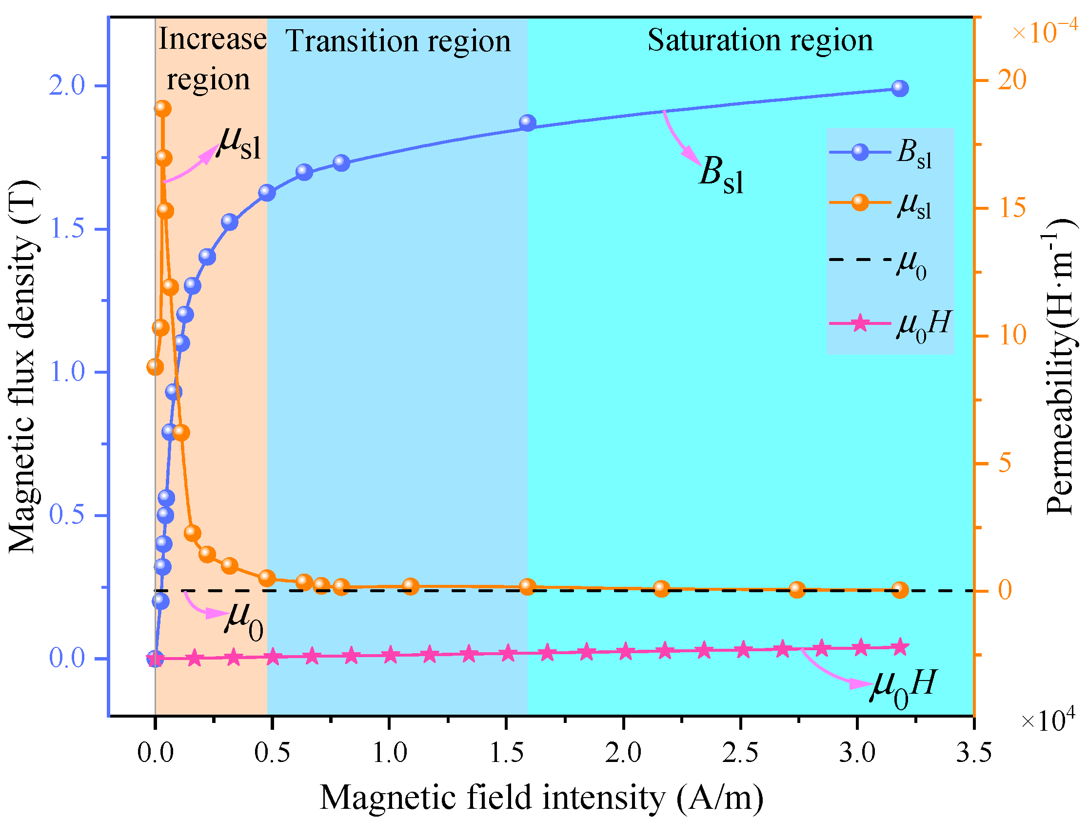
Saturation level of B-H curve of rotor core
B ag Magnetic flux density (MFD) of air gap
B ag-pm Magnitude of air gap magnetic flux density (MFD)
Φ ag Magnetic flux of air gap
B s Magnetic flux density (MFD) of stator
r s Radius of stator
ε 0 Vacuum permittivity
μ 0 Vacuum permeability
I y Component of the eddy current in the y-direction
ω f Electromagnetic field alternating angular velocity
μ r Relative permeability of stator material
n Rotational speed of rotor
J m Current density of conductor surface
P Eddy current loss, i.e., the thermal power

References

  1. Zhuo, C. Evaluating emission reduction potential at the ‘30-60 Dual Carbon targets’ over China from a view of wind power under climate change. Sci. Total Environ. 2023, 900, 165782. [Google Scholar] [CrossRef]
  2. Ruan, Z. Spatiotemporal carbon footprint and associated costs of wind power toward China’s carbon neutrality. Resour. Conserv. Recycl. 2024, 205, 107593. [Google Scholar] [CrossRef]
  3. Fang, Y.; Fan, R.; Shao, Z.; Yue, Y.; Liu, Z. Research on the cost allocation mechanism of wind power heating in China from a cost-benefit perspective. Energy Rep. 2024, 11, 4622–4630. [Google Scholar] [CrossRef]
  4. Zhang, M.; Cong, N.; Song, Y.; Xia, Q. Cost analysis of onshore wind power in China based on learning curve. Energy 2024, 291, 130459. [Google Scholar] [CrossRef]
  5. Ji, J.; Chi, Y.; Yin, X. The blue treasure of hydrogen energy: A research of offshore wind power industry policy in China. Int. J. Hydrog. Energy 2024, 62, 99–108. [Google Scholar] [CrossRef]
  6. GWEC. Global Wind Report 2024. Global Wind Energy Council. 2024, p. 75. Available online: http://www.gwec.net/global-figures/wind-energy-global-status/ (accessed on 23 May 2024).
  7. Zhang, F.; Salimu, A.; Ding, L. Operation and optimal sizing of combined P2G-GfG unit with gas storage for frequency regulation considering curtailed wind power. Int. J. Electr. Power Energy Syst. 2022, 141, 108278. [Google Scholar] [CrossRef]
  8. Zheng, J.; Zhou, Z.; Zhao, J.; Hu, S.; Wang, J. Effects of intermittent heating on an integrated heat and power dispatch system for wind power integration and corresponding operation regulation. Appl. Energy 2021, 287, 116536. [Google Scholar] [CrossRef]
  9. Zhang, L.; Yin, Q.; Zhang, Z.; Zhu, Z.; Lyu, L.; Hai, K.L.; Cai, G. A wind power curtailment reduction strategy using electric vehicles based on individual differential evolution quantum particle swarm optimization algorithm. Energy Rep. 2022, 8, 14578–14594. [Google Scholar] [CrossRef]
  10. Wiatros-Motyka, M. Global Electricity Review: Global Trends. Ember. 2023. Available online: https://ember-climate.org/Global-Electricity-Review-2023.pdf (accessed on 26 May 2024).
  11. Karijadi, I.; Chou, S.Y.; Dewabharata, A. Wind power forecasting based on hybrid CEEMDAN-EWT deep learning method. Renew. Energy 2023, 218, 119357. [Google Scholar] [CrossRef]
  12. Gong, M.; Yan, C.; Xu, W.; Zhao, Z.; Li, W.; Liu, Y.; Li, S. Short-term wind power forecasting model based on temporal convolutional network and Informer. Energy 2023, 283, 129171. [Google Scholar] [CrossRef]
  13. Li, L.; Zhu, D.; Zou, X.; Hu, J.; Kang, Y.; Guerrero, J.M. Review of frequency regulation requirements for wind power plants in international grid codes. Renew. Sustain. Energy Rev. 2023, 187, 113731. [Google Scholar] [CrossRef]
  14. Chen, H.; Chen, J.; Han, G.; Cui, Q. Winding down the wind power curtailment in China: What made the difference? Renew. Sustain. Energy Rev. 2022, 167, 112725. [Google Scholar] [CrossRef]
  15. Yang, M.; Wang, D.; Xu, C.; Dai, B.; Ma, M.; Su, X. Power transfer characteristics in fluctuation partition algorithm for wind speed and its application to wind power forecasting. Renew. Energy 2023, 211, 582–594. [Google Scholar] [CrossRef]
  16. Li, N.; Dong, J.; Liu, L.; Li, H.; Yan, J. A novel EMD and causal convolutional network integrated with Transformer for ultra short-term wind power forecasting. Int. J. Electr. Power Energy Syst. 2023, 154, 109470. [Google Scholar] [CrossRef]
  17. Yuan, W.; Xin, W.; Su, C.; Cheng, C.; Yan, D.; Wu, Z. Cross-regional integrated transmission of wind power and pumped-storage hydropower considering the peak shaving demands of multiple power grids. Renew. Energy 2022, 190, 1112–1126. [Google Scholar] [CrossRef]
  18. Lei, Z.; Wang, G.; Li, T.; Cheng, S.; Yang, J.; Cui, J. Strategy analysis about the active curtailed wind accommodation of heat storage electric boiler heating. Energy Rep. 2021, 7, 65–71. [Google Scholar] [CrossRef]
  19. Xu, F.; Hao, L.; Chen, L.; Chen, Q.; Wei, M.; Min, Y. Discussions on the real potential of district heating networks in improving wind power accommodation with temperature feedback as one consideration. Energy Convers. Manag. 2021, 250, 114907. [Google Scholar] [CrossRef]
  20. Mu, Y.; Li, H.; Yu, X.; Jia, H.; Wang, M.; Hou, K.; Wang, Z. A scenario-based optimal dispatch for joint operation of wind farms and combined heat and power plants considering energy flexibilities in heating networks. Electr. Power Syst. Res. 2022, 204, 107683. [Google Scholar] [CrossRef]
  21. Xu, F.; Hao, L.; Chen, L.; Chen, Q.; Wei, M.; Min, Y. Integrated heat and power optimal dispatch method considering the district heating networks flow rate regulation for wind power accommodation. Energy 2023, 263, 125656. [Google Scholar] [CrossRef]
  22. CHIC. Industry Report 2023/Comprehensive Section-Overall Energy Development. Available online: https://www.chic.org.cn/home/Index/detail1?id=1778 (accessed on 28 May 2024).
  23. Nourollahi, R.; Zare, K.; Mohammadi-Ivatloo, B.; Vahidinasab, V.; Moghadam, A.A. Continuous-time optimization of integrated networks of electricity and district heating under wind power uncertainty. Appl. Therm. Eng. 2023, 225, 119926. [Google Scholar] [CrossRef]
  24. Wang, W.; Dong, Z. Economic benefits assessment of urban wind power central heating demonstration project considering the quantification of environmental benefits: A case from northern China. Energy 2021, 225, 120246. [Google Scholar] [CrossRef]
  25. Cheng, W.L.; Han, B.C.; Le Nian, Y.; Han, B.B. Theoretical analysis of a wind heating conversion and long distance transmission system. Energy Convers. Manag. 2017, 137, 21–33. [Google Scholar] [CrossRef]
  26. Liu, X.H.; Chen, C.C.; Yu, H.D.; Wei, G.D.; De Tian, Z. The study of the heat device in wind-magnetic water heater. Adv. Mater. Res. 2011, 201–203, 460–464. [Google Scholar] [CrossRef]
  27. Sobor, I.; Chicuic, A.; Ciuperca, R.; Rachier, V. Concerning the conversion efficiency increase of the available wind potential. Ann. Univ. Craiova Electr. Eng. Ser. 2011, 35, 122–127. Available online: http://elth.ucv.ro/fisiere/anale/2011/19.pdf (accessed on 2 April 2024).
  28. Cao, K.K.; Nitto, A.N.; Sperber, E.; Thess, A. Expanding the horizons of power-to-heat: Cost assessment for new space heating concepts with Wind Powered Thermal Energy Systems. Energy 2018, 164, 925–936. [Google Scholar] [CrossRef]
  29. Liu, X. The study of power unit of a wind-magnetic water heater. Adv. Mater. Res. 2012, 418–420, 2290–2293. [Google Scholar] [CrossRef]
  30. Du, H.; Qu, Y.; Cheng, S. A novel dynamic electromagnetic heating-magnetizing device used for reverse osmosis system. Adv. Mater. Res. 2012, 562–564, 913–916. [Google Scholar] [CrossRef]
  31. Du, H.; Qu, Y. Research on loss and temperature rise of a novel dynamic electromagnetic induction heater. Adv. Mater. Res. 2012, 468–471, 3108–3112. [Google Scholar] [CrossRef]
  32. Shukang, C.; Lei, C.; Yunpeng, H. Fundamental research on flameless electromagnetic heater based on the reverse problem of temperature rise and loss in electrical machines. In Proceedings of the IEEE Vehicle Power & Propulsion Conference, Harbin, China, 3–5 September 2008. [Google Scholar]
  33. Chu, J. Mathematic model based on rotating electromagnetic theory used in building a thermal circuit used in food heater. Carpathian J. Food Sci. Technol. 2016, 8, 106–113. [Google Scholar]
  34. Tudorache, T.; Popescu, M. FEM optimal design of wind energy-based heater. Acta Polytech. Hung. 2009, 6, 55–70. [Google Scholar]
  35. Dirba, I.; Kleperis, J. Practical application of eddy currents generated by wind. IOP Conf. Ser. Mater. Sci. Eng. 2011, 23, 012011. [Google Scholar] [CrossRef]
  36. Fireeanu, V.; Nebi, O. Finite element electromagnetic 2D model of an eddy current heater with rotating permanent magnets. Ann. Univ. Craiova Electr. Eng. Ser. 2008, 32, 62–67. [Google Scholar]
  37. Khanjari, A.; Kang, S.; Lee, D.; Jung, D.Y.; Lee, J.H. Studying Four Different Permanent Magnet Eddy Currents Heaters with Different Magnet Areas and Numbers to Produce Heat Directly from a Vertical Axis Wind Turbine. Energies 2022, 15, 275. [Google Scholar] [CrossRef]
  38. Khanjari, A.; Kang, S.; Lee, S.I.; Lee, J.H.; Kim, Y.S. Direct heat energy harvesting from wind by a permanent magnet eddy currents heater with different magnet arrangements. Energy Sci. Eng. 2023, 11, 929–951. [Google Scholar] [CrossRef]
  39. Sobor, I.; Rachier, V.; Chicuic, A.; Ciuperca, R. Small wind energy system with permanent magnet eddy current heater. Bull. Polytech. Inst. Jassy Elechtrotechnics Energetics Electron. Sect. 2013, 13, 143–150. Available online: http://www.bulipi-eee.tuiasi.ro/archive/2013/fasc.4/2013f4contents.html (accessed on 4 April 2024).
  40. Chen, L.; Pei, Y.; Chai, F.; Cheng, S. Investigation of a Novel Mechanical to Thermal Energy Converter Based on the Inverse Problem of Electric Machines. Energies 2016, 9, 518. [Google Scholar] [CrossRef]
  41. Nebi, O.; Fireţeanu, V. Finite element analysis of an eddy current heater for wind or water kinetic energy conversion into heat. Renew. Energy Power Qual. J. 2010, 1, 882–887. [Google Scholar] [CrossRef]
  42. Tudorache, T.; Melcescu, L. Outer rotor eddy current heater for wind turbines. Renew. Energy Environ. Sustain. 2016, 1, 25. [Google Scholar] [CrossRef]
  43. Du, H.; Li, J.; Qu, Y. Mathematical modeling of eddy-current loss for a new induction heating device. Math. Probl. Eng. 2014, 2014, 923745. [Google Scholar] [CrossRef]
  44. Tudorache, T.; Trifu, I.; Melcescu, L.; Floricau, D. Numerical analysis of an electro-thermal wind generator. In Proceedings of the 9th International Conference on Electronics, Computers and Artificial Intelligence, ECAI 2017, Targoviste, Romania, 29 June–1 July 2017; pp. 1–4. [Google Scholar] [CrossRef]
  45. Tudorache, T.; Melcescu, L.; Bostan, V.; Colț, G.; Popescu, M.; Predescu, M. Electromagnetic analysis of a hybrid permanent magnet generator. IEEE Trans. Energy Convers. 2018, 63, 33–37. [Google Scholar]
  46. Grigorash, O.; Kirichenko, A.; Pigarev, K. Model of Induction Heater on Permanent Magnets Using Wind Energy. In Proceedings of the 2019 International Conference on Industrial Engineering, Pilsen, Czech Republic, 23–26 July 2019. [Google Scholar]
  47. Tudorache, T.; Melcescu, L.; Predescu, M. Analysis of a permanent magnet Eddy current heater driven by a wind turbine. Adv. Electr. Comput. Eng. 2015, 15, 53–58. [Google Scholar] [CrossRef]
  48. Song Zhihao, Y.W.W. Modeling of Interior PMSM Based on Normal Canonical Form Under Low Carrier Ratio. Proc. CSEE 2023, 43, 4779–4788. (In Chinese) [Google Scholar] [CrossRef]
  49. Liu, F.; Wang, X.; Xing, Z.; Yu, A.; Li, C. Reduction of Cogging Torque and Electromagnetic Vibration Based on Different Combination of Pole Arc Coefficient for Interior Permanent Magnet Synchronous Machine. CES Trans. Electr. Mach. Syst. 2021, 5, 291–300. [Google Scholar] [CrossRef]
  50. Karakoc, K.; Park, E.J.; Suleman, A. Improved braking torque generation capacity of an eddy current brake with time varying magnetic fields: A numerical study. Finite Elem. Anal. Des. 2012, 59, 66–75. [Google Scholar] [CrossRef]
  51. Chen, Q.; Xu, G.; Liu, G.; Zhao, W.; Liu, L.; Lin, Z. Torque ripple reduction in five-phase IPM motors by lowering interactional MMF. IEEE Trans. Ind. Electron. 2018, 65, 8520–8531. [Google Scholar] [CrossRef]
  52. Liu, G.; Liu, L.; Chen, Q.; Zhao, W. Torque Calculation of Five-Phase Interior Permanent Magnet Machine Using Improved Analytical Method. IEEE Trans. Energy Convers. 2019, 34, 1023–1032. [Google Scholar] [CrossRef]
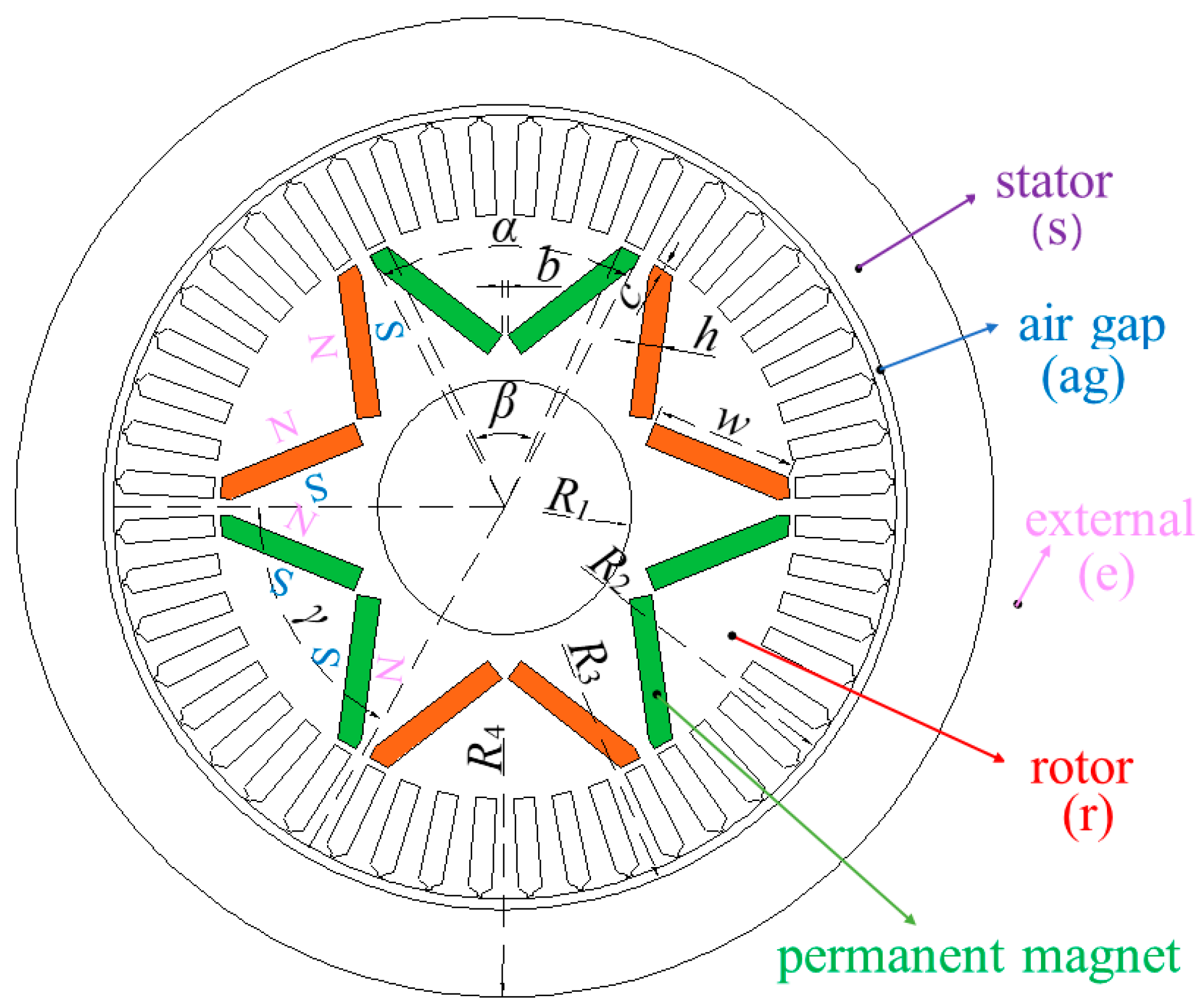
Figure 1. PMECH driven by a wind turbine.
Processes 12 01457 g001
Figure 2. Structure of IPMECH.
Processes 12 01457 g002
Figure 3. Simplified model of an IPMECH.
Processes 12 01457 g003
Figure 4. Equivalent magnetic circuit.
Processes 12 01457 g004
Figure 5. B-H curve of rotor core.
Processes 12 01457 g005
Figure 6. Charge distribution within the stator conductor micro-elements.
Processes 12 01457 g006
Figure 7. Verification of mesh and time step independence.
Processes 12 01457 g007
Figure 8. Air gap MFD of IPEMCH.
Processes 12 01457 g008
Figure 9. The MFD distribution at different locations of the heater.
Processes 12 01457 g009
Figure 10. Electromagnetic of AM and FEM at different rotational speeds..
Processes 12 01457 g010
Figure 11. The FEM and AM thermal power at different rotational speeds.
Processes 12 01457 g011
Figure 12. The IPMECH experimental platform.
Processes 12 01457 g012
Figure 13. Temperature variation of the inlet and outlet of the IPMECH.
Processes 12 01457 g013
Figure 14. The comparison of the FEM, AM, and experimental electromagnetic torque at different speeds of the IPMECH.
Processes 12 01457 g014
Figure 15. The comparison of the FEM, AM and experimental thermal power at different speeds of the IPMECH.
Processes 12 01457 g015
Table 1. Structural parameters of the IPMECH.
ParametersVariableValue
The maximum angles of the permanent magnet (°)α56.0
The minimum angles of the permanent magnet (°)β48.0
Angle of adjacent poles (°) γ 60.0
Thickness of flux barrier b (mm)b1.03
Thickness of flux barrier c (mm)c1.3
Thickness of permanent magnet (mm)h4.0
Length of permanent magnet (mm)w27.2
Radius of rotor shaft (mm)R124.0
Outer radius of the rotor (mm)R274.0
Inner radius of the stator (mm)R374.5
Outer radius of the stator (mm)R492.5
Disclaimer/Publisher’s Note: The statements, opinions and data contained in all publications are solely those of the individual author(s) and contributor(s) and not of MDPI and/or the editor(s). MDPI and/or the editor(s) disclaim responsibility for any injury to people or property resulting from any ideas, methods, instructions or products referred to in the content.

