Abstract
Bypass diffusers are used to drain the excess steam generated in the steam generator in case of sudden load reduction or shutdown of the steam turbine. However, the steam at the orifice outlet with the high flow velocity may reverse into the space of last-stage blades and cause forced vibration of the turbine blades. For this study, a full-scale CFD calculation model which couples the last stage and the second-last stage with the bypass diffusers was constructed. The fluid dynamic characteristics of the high-speed steam discharged from the outlet of the bypass diffusers and the effect of steam on the last-stage rotating blades were analyzed comprehensively via both steady and transient numerical methods. The steady results show that the steam at the orifice outlet of the bypass diffusers presents a typical jet flow with some steam flowing back into the last-stage blades region through the exhaust of the cylinders. This results in a notable disturbance to the last-stage rotating blades, characterized by a non-uniform circumferential pressure distribution. The transient numerical simulation results reveal that the outlet mass flow rate of the steam from the second-last-stage stationary blades has a significant effect on both the Mach number distribution and the surface forces acting on the last-stage rotating blades. The higher outlet mass flow rate of the steam escalates the instability of the flow field. The difference in the Mach number at the same position can reach as high as 60% or more under different operating conditions. The forces acting on the last-stage rotating blades in different directions change periodically with time, and the magnitude and period of the variation correlate with the outlet mass flow rate of the steam.
1. Introduction
Bypass diffusers play an important role in the nuclear power plant steam turbine, whose main function is to drain the excess steam generated in the steam generator in case of sudden load reduction or shutdown of the steam turbine [1]. During the thermal shutdown and initial cooling of the nuclear power plant, the residual heat in the reactor and the sensible heat in the primary system are removed until the residual heat removal system is put into use. Without a bypass system, the steam generated must be discharged into the atmosphere, resulting in a loss of valuable condensate water and severe environmental noise pollution concerns. However, if the discharge of high-speed steam from the bypass diffusers is not handled properly, the steam will likely exceed the thermal limits of the downstream piping and system equipment [2]. Moreover, it will cause other problems, such as causing the corrosion of the condenser tubes [3], tube vibration, or even damage, among other effects, which will affect the operating efficiency and endanger the safety of the condenser.
The condenser has a great impact on the safe and stable operation of the entire nuclear power plant [4,5]. The design of steam surface condensers is typically based on the HEI Standards for Steam Surface Condensers [6]. The Electric Power Research Institute (EPRI) also proposes guidelines and recommendations for high-energy fluids entering surface condensers [7]. Their suggestions put forward that the primary principle for dealing with the high-energy fluids discharging into the condenser is to prevent accidents and ensure the safe and reliable operation of the condenser. The key parameters should be considered, including the enthalpy limits, line velocity, and the safe discharge distance of the high-energy fluids. Different experts have modified the structure of the existing bypass diffusers to ensure the condenser’s safety. By drilling on the upper section of smaller branch headers and installing a hood, Nightingale [8] dramatically reduced the steam velocities at the interface of the tube bundle to keep proper discharge distance and, therefore, ensure the safety of the cooling tubes and other structural components. Compared to traditional thermal power units, the bypass fluid from nuclear power plant turbines has characteristics such as a higher flow rate and higher energy level. Ensuring the safety of condensers in nuclear power plant turbines is therefore receiving increasing attention. Connors [9] provided guidelines for the maximum space required for support plates to elude the vibration of heat transfer tubes when the bypass diffusers are running.
In addition to the impact of high-speed steam on condensers, if the energy level and the flow rate of the steam entering the diffusers are high enough, the steam discharged from the orifice outlet with a high flow velocity may reverse into the space of the last-stage blades. The disordered steam flow introduced is likely to cause forced vibration of the turbine blades, which will lead to the cracking or even partial shedding of the blade lacing boss. During the maintenance of a certain nuclear power unit in Taishan Nuclear Power Joint Venture Co., Ltd., in July 2020, the local detachment and cracking of the lacing lug of the last-stage blade in the low-pressure turbine were observed, exerting a serious influence on the safe and stable operation of the nuclear power units. This may be due to the forced vibration of the blades under the disturbance of turbulent steam flow from the bypass diffusers during the bypass exhaust. It can be concluded that the steam discharged from the bypass diffusers may not only bring potential safety hazards to the condenser but also affect the flow field characteristics in the low-pressure cylinders, which threatens the safety and economical operation of the nuclear power plant. However, the effect of high-speed steam discharged from the bypass diffusers on low-pressure turbine blades has not been reported. Therefore, the research on the flow characteristics of high-speed steam from the bypass diffusers and its influence on the low-pressure turbine blades has important engineering significance for the safe operation of steam turbines in nuclear power plants.
Overall, bypass diffusers are mainly used to throttle and depressurize the main steam and discharge it into the condenser to ensure the safe operation of the system. The existing fundamental design standards for bypass units including steam velocity and safe distances are mostly considered for the safe and steady operation of condenser structures. However, the influence of the high-speed steam at the outlet of the bypass diffusers on the flow field and the blade stress in the low-pressure cylinders is not considered. Therefore, it is necessary to construct a full-scale CFD calculation which couples the last-stage blades in low-pressure cylinders with the bypass diffusers to analyze the fluid dynamic characteristics of the high-speed steam at the outlet of the bypass diffusers and the effect of the steam on last-stage rotating blades.
2. Computational Method
2.1. Physical Model and Computational Domain
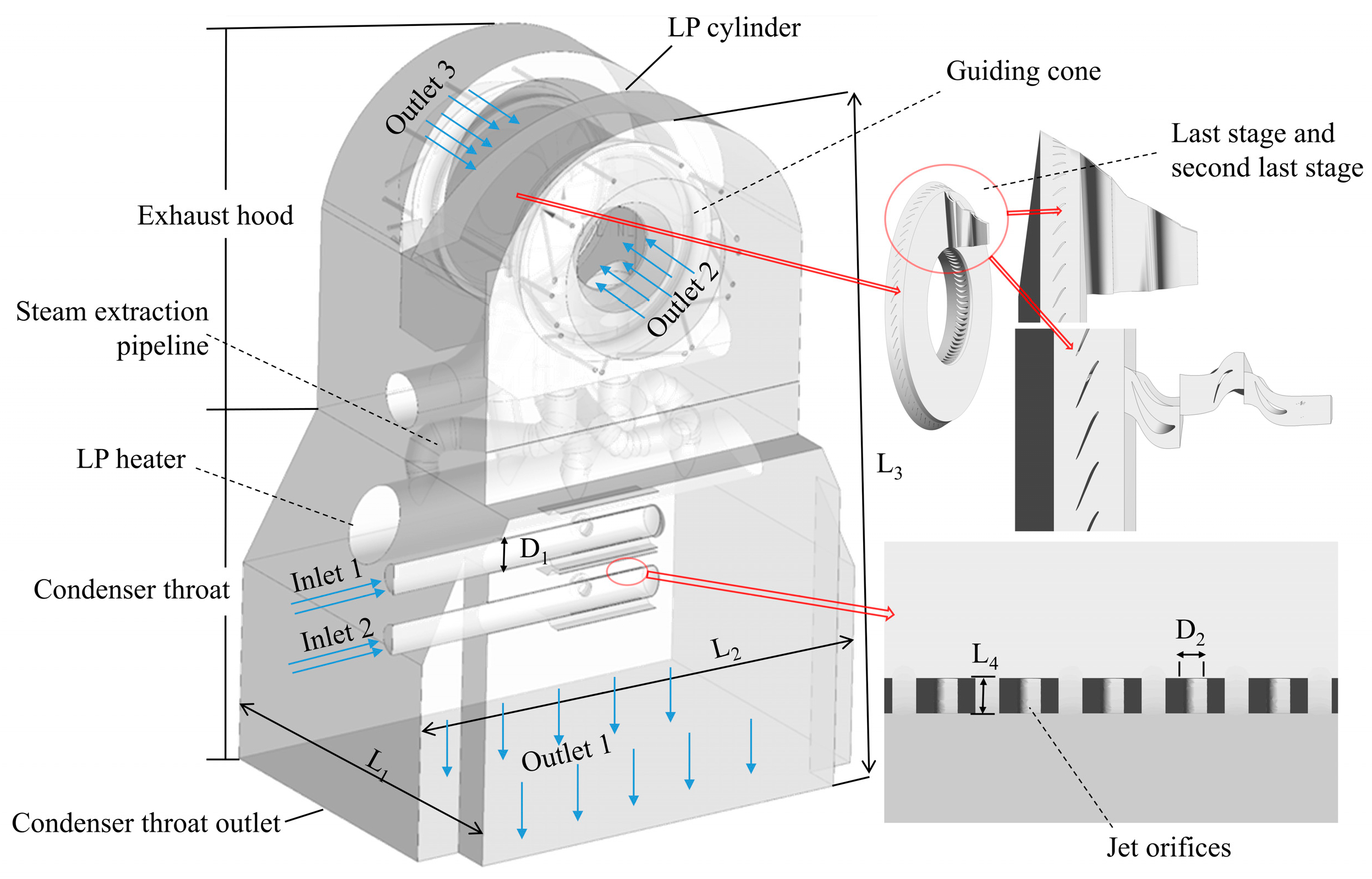
A physical model including the bypass diffusers, the last-stage and the second-last-stage blades, and steam extraction pipelines is constructed as shown in Figure 1. There are a great number of jet orifices arranged on the bypass diffusers, with 8 rows and 50 rows of jet orifices on both the upper and lower sides of the pipelines. The key geometric dimensions are listed in Table 1. The physical model employed in this paper boasts a volume of 2608.02 m3. Since the bypass diffusers are located at one side, the overall model has geometrical asymmetry. As a result, the flow field in the low-pressure cylinders does not have cyclic symmetry. Therefore, full passage simulations for the last-stage rotating blades (a circle of 65 blades) and single flow passage simulation for the remaining last-stage stationary blades (a circle of 70 blades) and the second-last-stage rotating (a circle of 72 blades) and stationary blades (a circle of 82 blades) are conducted.
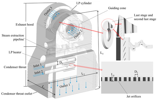
Figure 1.
Full-scale physical model.

Table 1.
Key geometric dimensions of the physical model.
2.2. Grid Generation
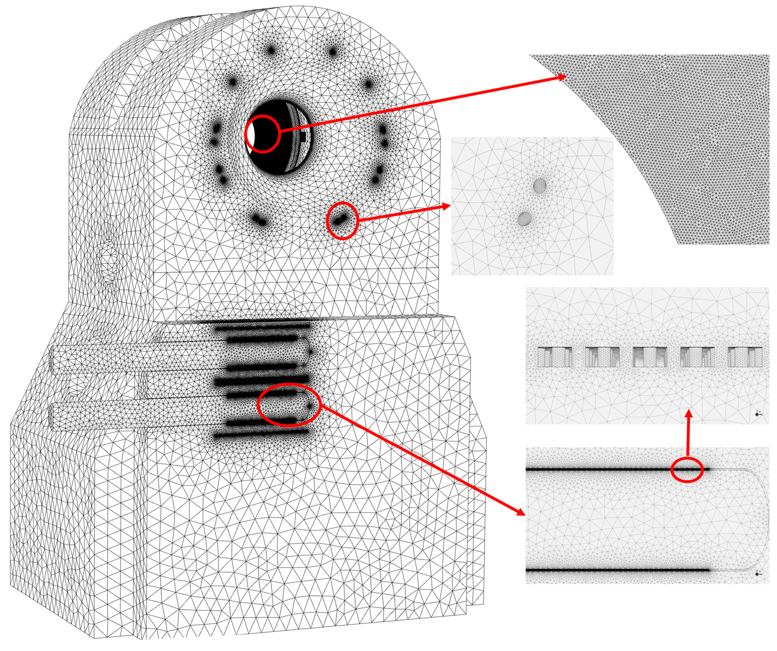
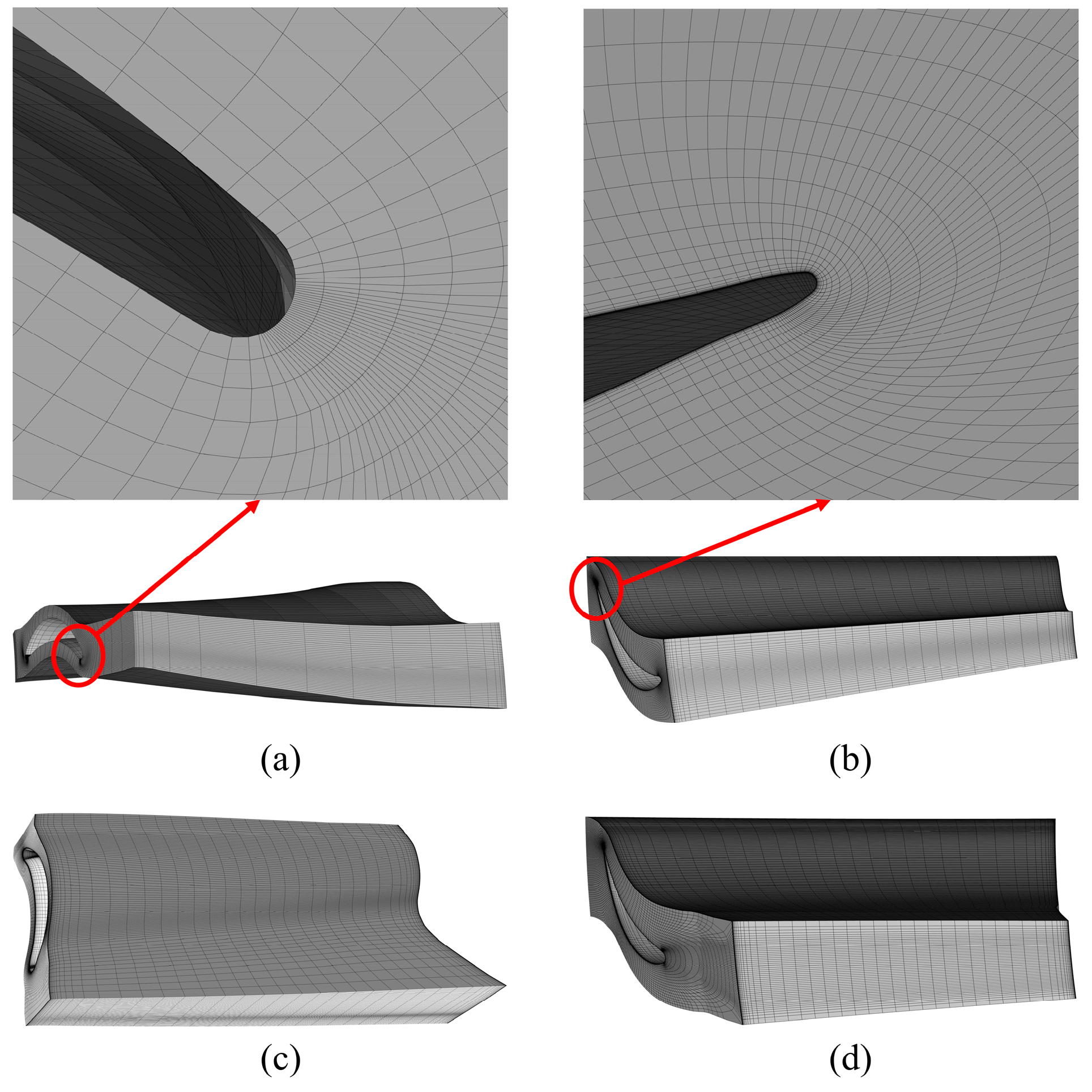
The computational model comprises two sections: the primary section, which is composed of many complex pipelines, undergoes discretization to obtain unstructured tetrahedral meshes. Local grid refinement is adopted to enhance simulation accuracy near the flow guide baffles and jet orifices. The structured mesh for the blade rows is generated, and a grid diagram of the computational domain is shown in Figure 2. The CFD mesh around the stationary and rotating blades is shown in Figure 3.
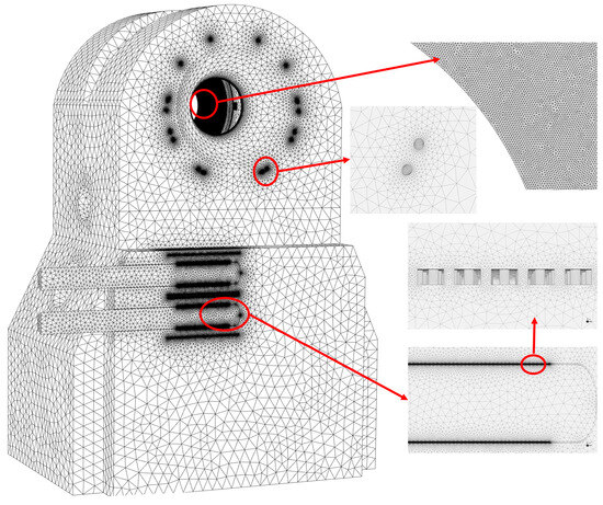
Figure 2.
A grid diagram of the computational domain.
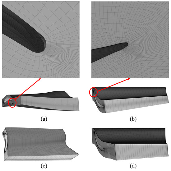
Figure 3.
CFD mesh around the rotating and stationary blades: the last-stage blades (a,b) and the second-last-stage blades (c,d).
The entirety of the fluid domain incorporates numerous jet orifices and a variety of curved pipes, creating a highly complex structure. The grid independence verification is performed under the working condition when the outlet mass flow rate of fluid is 0.02 kg/s from a single stationary blade passage (the second-last stage). Because the physical model in this paper is very complex, the grid size varies in different regions. For example, the grid cell size ranges from 2.25 mm to 3.00 mm in the jet orifice regions, and the grid cell size ranges from 30.00 mm to 50.00 mm in the flow guide baffle regions. Five different grid sizes with total grid point values of 37.5 million, 39.5 million, 41.5 million, 43.5 million, and 45.5 million were tested for analysis. The grid independence verification is shown in Table 2. It is shown that as the grid points increase to 41.5 million, the maximum Mach number in the flow field converges to stable values, and the calculation results are almost unchanged with the high accuracy, which indicates the insensitivity of the calculation results to further grid refinement. Therefore, the proper grid number (41.5 million) is determined in the numerical simulation.
Table 2.
Grid independence verification.
2.3. Calculation Method and Boundary Conditions
A three-dimensional simulation is performed, and the k–ω-based Shear Stress Transport (SST) model, widely employed in engineering [10], is selected as the turbulent mixing model for both the steady and transient simulations. The SST model was originally proposed by Menter [11], and it utilizes a k–ω model in the near-wall region and a k–ε model away from the wall; it improves the prediction accuracy of flow separation [12]. The steam1vl equilibrium wet steam model is selected, and the thermodynamic properties of this model can be found in the IAPWS-IF97 working medium library [13].
The rotational speeds of the last-stage and the second-last-stage blades are set at 8 r/min and 7 r/min, respectively, with the X-axis serving as the rotational axis. The mass flow rate of the steam entering the bypass diffusers ranges between 33 and 130 kg/s, with a steam enthalpy of 2772 kJ/kg, and the corresponding steam pressure is in the range of 0.09 to 0.35 MPa. For the simulations discussed in this paper, the mass flow rate and the enthalpy of the working fluid entering the bypass diffusers are set to be 65 kg/s and 2772 kJ/kg, respectively. The boundary condition of the throat outlet of the condenser is set to “pressure outlet”, with a back pressure of 5 kPa. The maximum outlet mass flow rate of steam from a single stationary blade passage (the second-last stage) is set to be 0.1 kg/s. This may be higher than the real value in the operation process, because under this condition, the fraction of the reflux steam accounts for 24.92% of the total mass flow rate of the steam discharged from the bypass diffusers. However, to investigate the effect of the high-speed steam on low-pressure turbine blades, it needs to cover a wider range of the outlet mass flow rate of steam. Therefore, the outlet mass flow rate of steam from a single stationary blade passage (the second-last stage) is set to be in the range of 0 to 0.1 kg/s. An interface is implemented to connect the rotating and the stationary regions together in the circumferential direction [14]. Fluid–fluid interfaces are established at the axial contact position between the rotating blades and the low-pressure cylinders, while the remaining walls are defined as no-slip wall boundary conditions [15]. The residual values of all parameters are set to converge below 10−5 during both the steady-state and transient numerical simulations. Additionally, the calculation is considered converged when the target monitoring values, such as the mass flow rate of the steam at the condenser outlet, tend towards certain values [16].
2.4. Empirical Formula Validation
High-speed steam will be discharged from the jet orifices on the bypass diffusers. The empirical equation for the calculation of the Mach number (Mj) of the steam from the jet orifices is as follows [7], as confirmed and validated in references [17,18]:
where Pi represents the total pressure at the inlet of the jet orifice, and P0 is the static pressure at the outlet.
By analyzing the results obtained by numerical calculation and the empirical equation, it is found that the difference in the Mach number of the steam at a certain location obtained by those two methods is lower than 5%, which confirms the high accuracy of the CFD numerical simulation method.
3. Calculation Results and Analysis
While the flow field inside the impeller machinery is typically three-dimensional, viscous, and transient due to factors such as the relative motion of the stationary and rotating blades, the steady method has been shown to yield satisfactory results in certain cases [19]. Therefore, the steady numerical method is first employed for a qualitative analysis of the flow field. Subsequently, the transient numerical method is employed to explore the extent of steam disturbance on the last-stage blades.
3.1. Steady-State Simulation
The steady-state simulation is carried out with the outlet mass flow rate of steam from a single stationary blade passage (the second-last stage) ranging from 0.01 kg/s to 0.1 kg/s to investigate the effect of the backflow steam on the last-stage rotating blades.
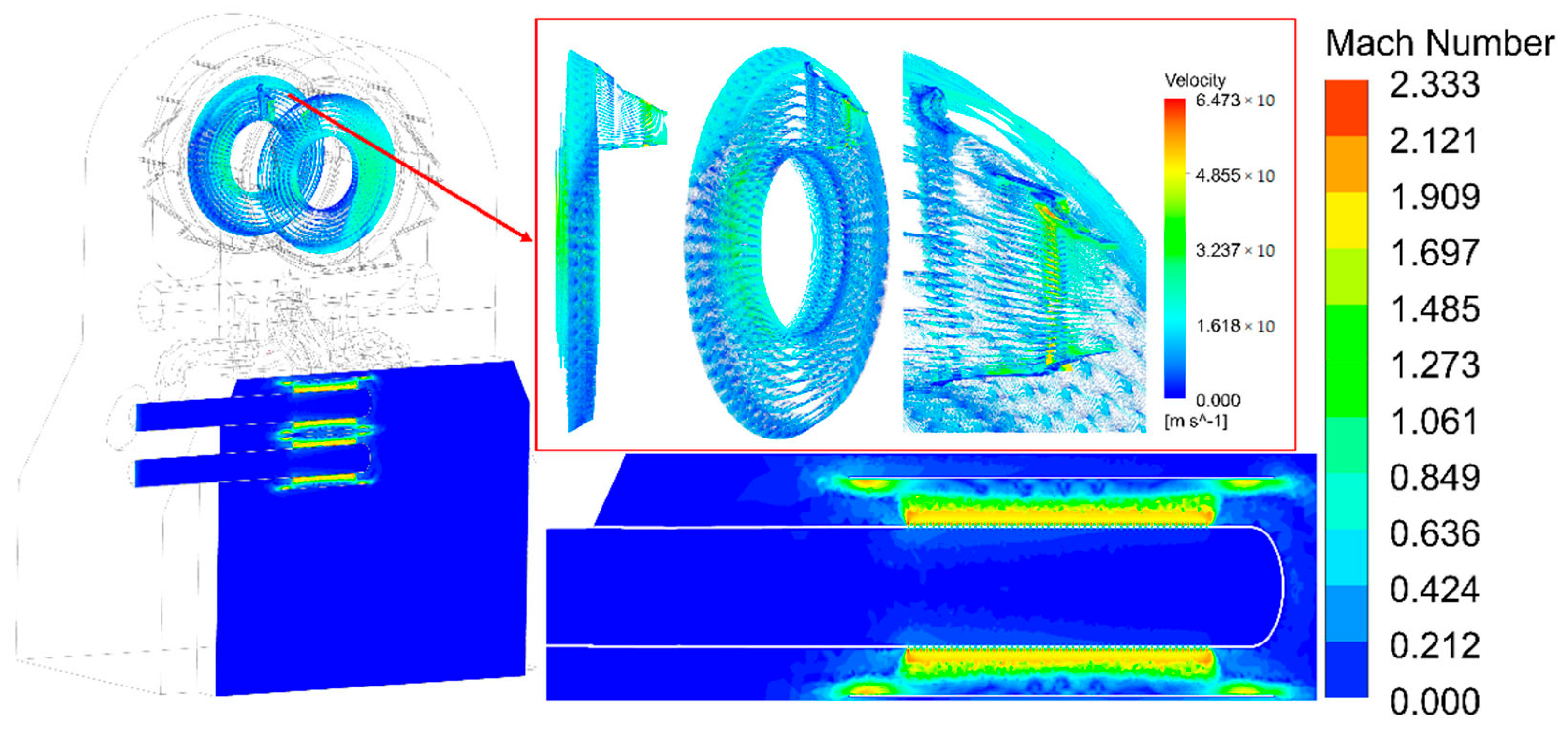
Figure 4 shows the velocity and Mach number contours when the outlet mass flow rate of the steam is 0.02 kg/s. It shows that the steam discharged from the bypass diffusers presents a typical jet flow with a maximum Mach number of 2.333. The streamlines in the model are shown in Figure 5. The steam reflux and large vortexes are observed in the low-pressure cylinders. This indicates that a portion of the steam reverses into the space of the last-stage blades. However, the velocity of the backflow steam in this region is relatively low.

Figure 4.
Velocity and Mach number contours in different regions (outlet steam mass flow rate: 0.02 kg/s).
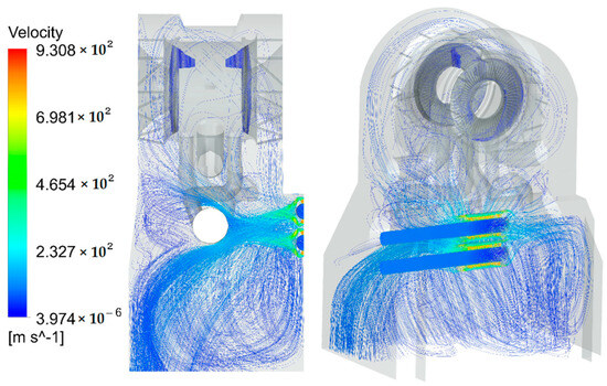
Figure 5.
Three-dimensional velocity streamline (outlet steam mass flow rate: 0.02 kg/s).
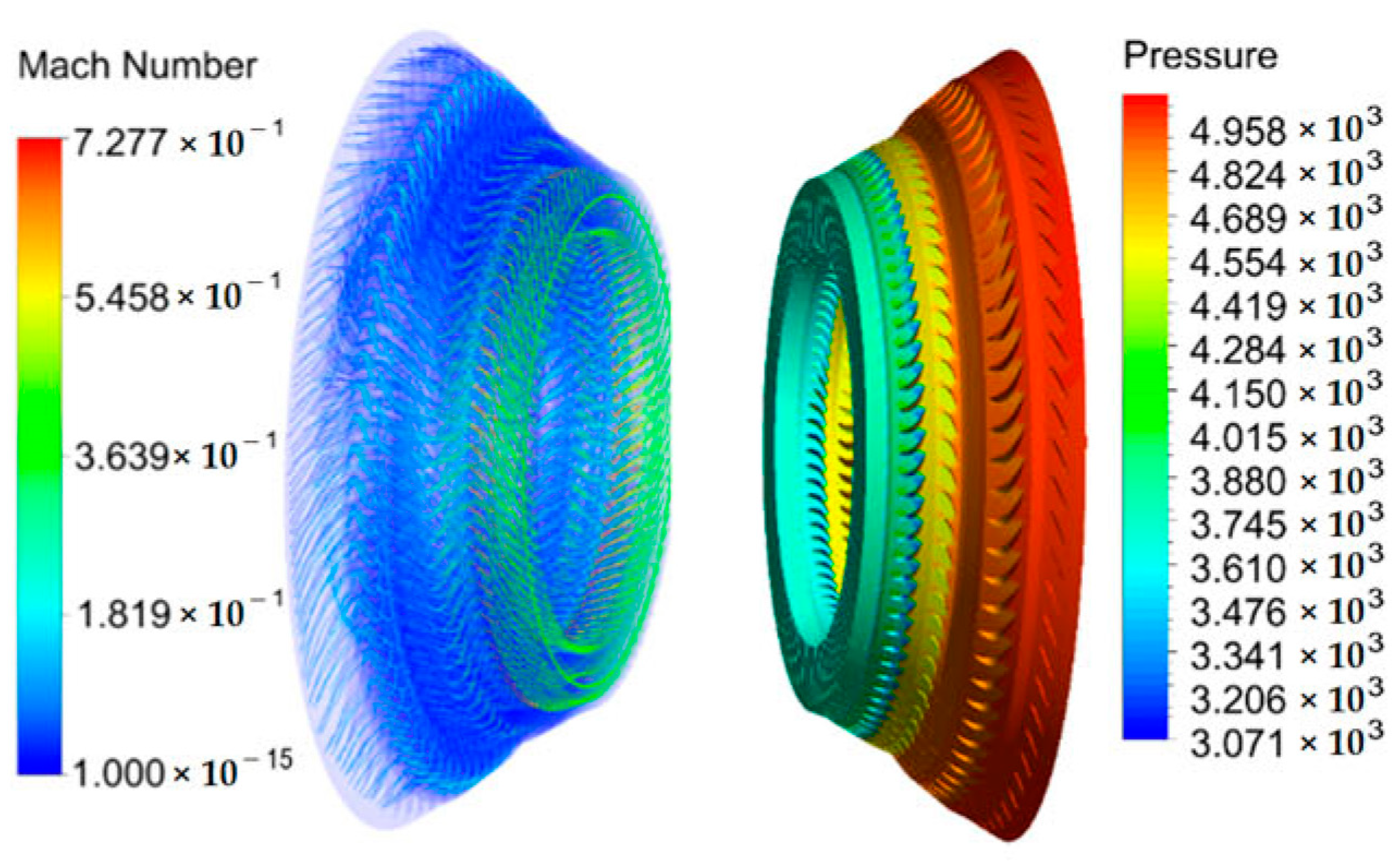
The Mach number and the pressure distribution over the last- and second-last-stage blade surfaces when the outlet mass flow rate of the steam is 0.1 kg/s are shown in Figure 6. The maximum Mach number in the region of the second-last-stage stationary blades reaches 0.728. This is attributed to the high mass flow rate of steam backflows into the stationary blade region.

Figure 6.
Mach number and the pressure distribution over the last- and second-last-stage blade surfaces (outlet steam mass flow rate: 0.1 kg/s).
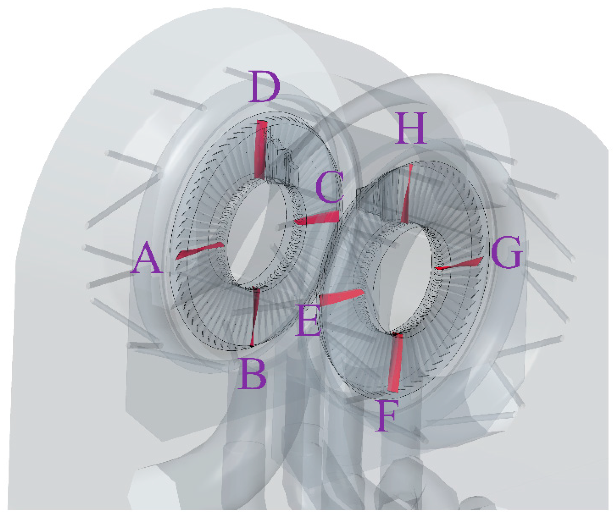
When the high-speed steam ejected from the jet orifices on the bypass diffusers flows back into the last-stage blade region, it will intensify the instability of the flow field. This phenomenon will cause an asymmetric pressure distribution, thus influencing the force on the blades. Moreover, unstable occurrences such as decoupling and reflux may appear when the steam flows into the space of the last-stage blades, which potentially amplifies the disturbance of the flow field. To assess the degree of disturbance, eight representative blades, depicted in Figure 7, are selected to monitor the surface force on the last-stage rotating blades. These blades are situated in both positive and negative directions along the Y-axis and Z-axis, respectively.
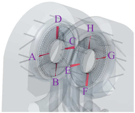
Figure 7.
The eight monitored rotating blades which are named from A to H.
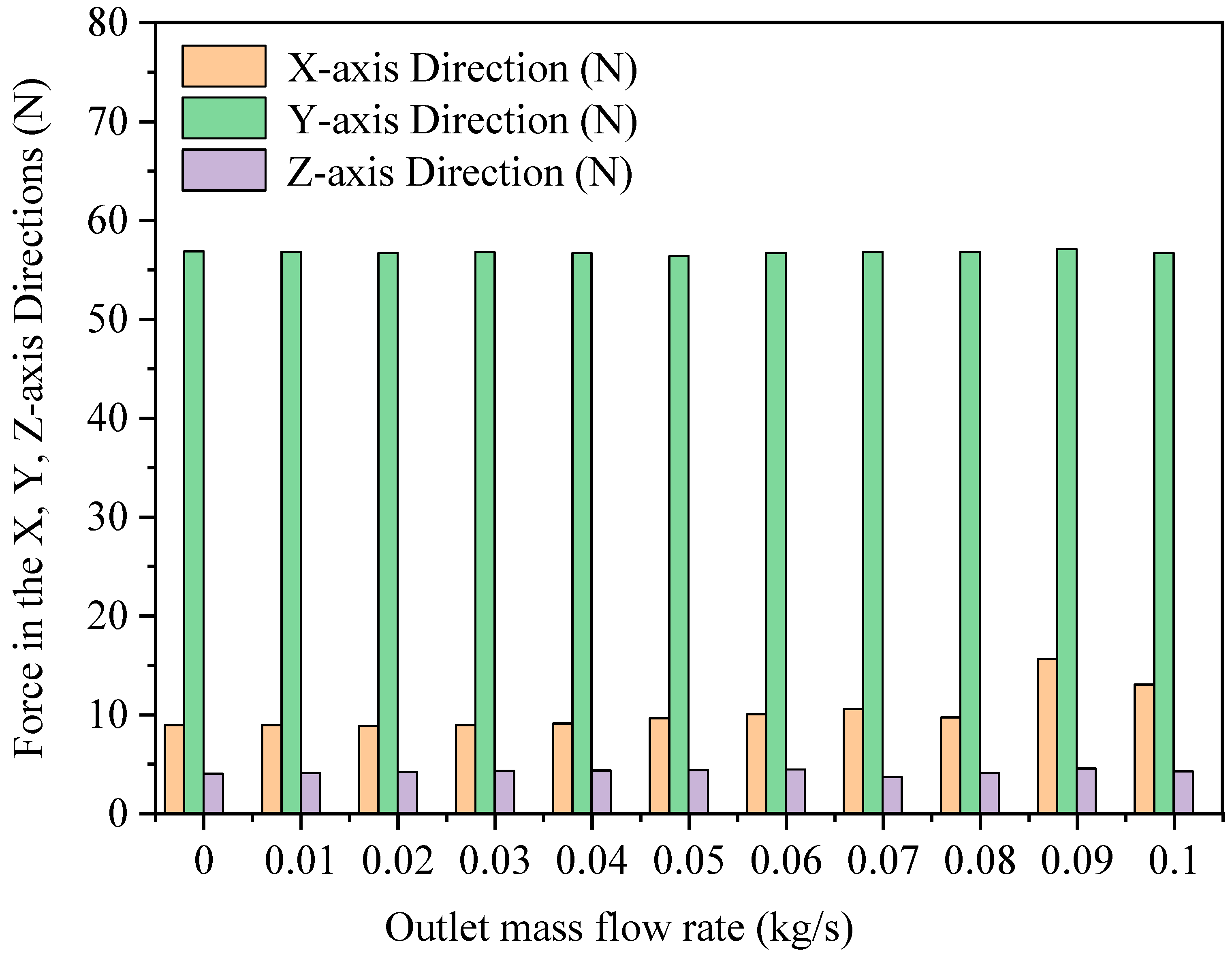
The absolute values of the maximum force acting on the eight rotating blades in the X-, Y-, and Z-axis directions at different outlet mass flow rates of the steam are shown in Figure 8. It can be found that the values of the force in the X, Y, and Z-axis directions almost remain constant when the outlet flow rate of the steam from a single stationary blade passage ranges from 0 to 0.08 kg/s.
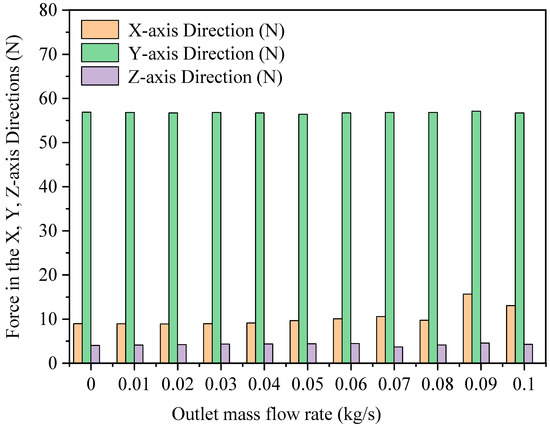
Figure 8.
Variation in maximum force in X-, Y-, and Z-axis directions with the outlet mass flow rate of steam.
3.2. Transient Simulation
Although the results of the steady-state simulation under different working conditions are compared and analyzed to obtain the change in the surface forces acting on the last-stage rotating blades, the forces are not constant when the residuals are sufficiently small. Therefore, to obtain the values of the force acting on the surfaces of the last-stage rotating blades with operation time under different conditions, it is evidently necessary to conduct a transient simulation to characterize the flow field when the high-speed steam is discharged from the bypass diffusers.
3.2.1. The Transient Characteristics of the Flow Field
The steady-state simulation results indicate that the forces acting on the surfaces of the last-stage rotating blades are almost stable when the outlet mass flow rate of steam from a single stationary blade passage (the second-last stage) is in the range of 0–0.08 kg/s. Three different cases with outlet steam mass flow rates of 0, 0.02, and 0.05 kg/s, respectively, are set up for comparison.
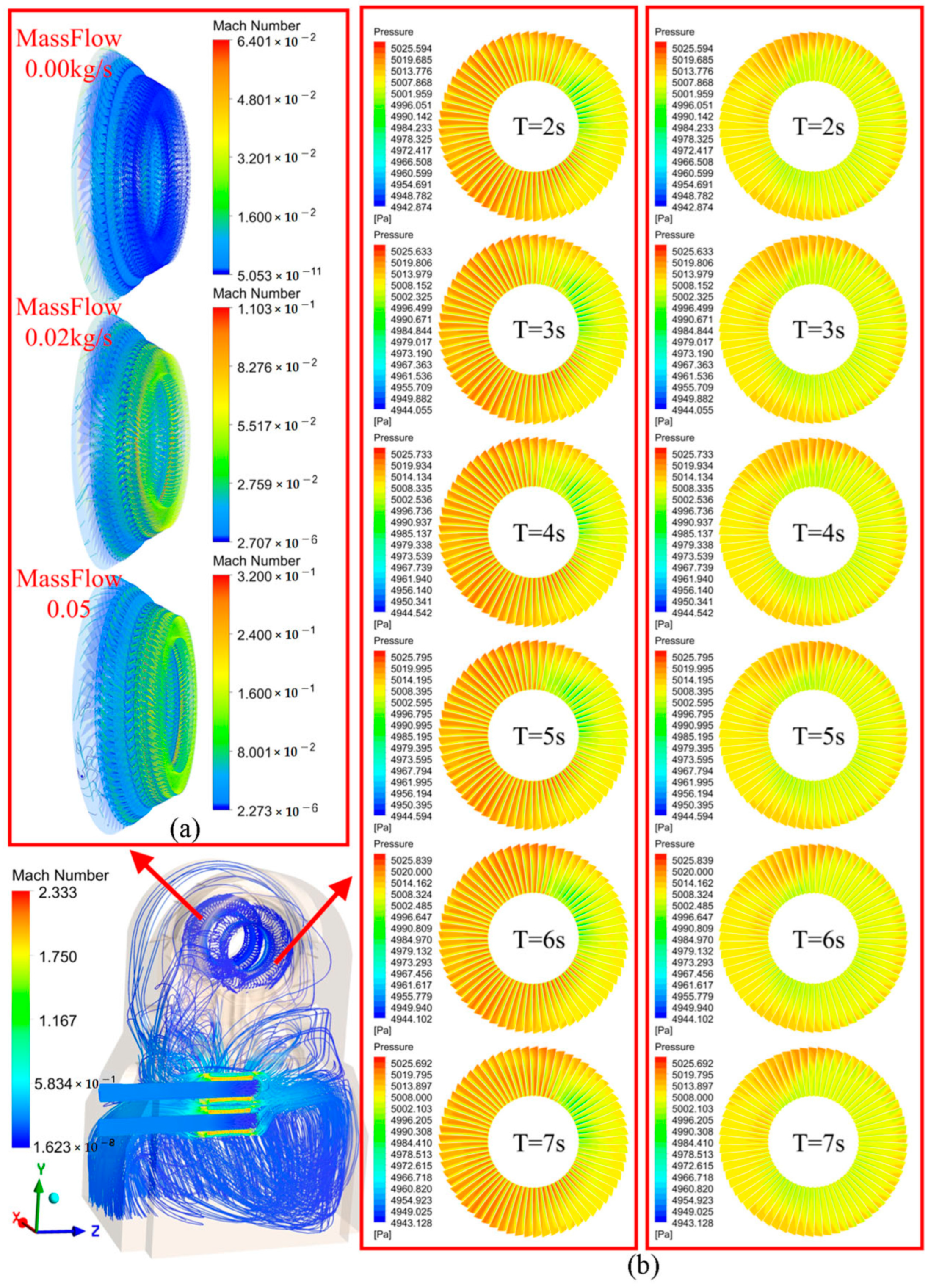
Figure 9 shows the Mach number distribution at different positions and different times when the outlet mass flow rate of steam from a single stationary blade passage (the second-last stage) is 0.05 kg/s. The flow with the high Mach number is primarily concentrated in the region spanning from the jet orifices to the flow guide baffles, with the Mach number ranging from 0.5 to 2.333. A is the position where the maximum Mach number is located at 7.5 s.
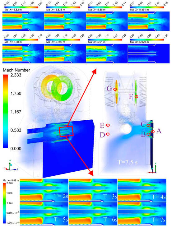
Figure 9.
Mach number distribution at different positions and times.
Figure 10 shows the Mach number and the pressure distribution over the last-stage rotating blade surfaces at different times. When the high-speed steam flows back to the low-pressure cylinders, the evident transient characteristics in the flow field near the rotating blades appear. The Mach number distribution and the surface pressure distribution change with time. The results show that an increase in the outlet mass flow rate of the steam from the second-last stationary blades intensifies the transient flow characteristics in the impeller region. Figure 10b shows the pressure distributions on the pressure surface and the suction surface of the last-stage rotating blades at different moments when the outlet mass flow rate of steam is set to be 0.05 kg/s. The results reveal an uneven circumferential distribution of pressure on the last-stage rotating blades. The circumferential pressure distribution pattern remains consistent at different moments. Moreover, the pressure distributions on the pressure surface and the suction surface are different in the radial direction. The high-pressure region on the suction surface (X-axis negative direction) is smaller than that on the pressure surface.
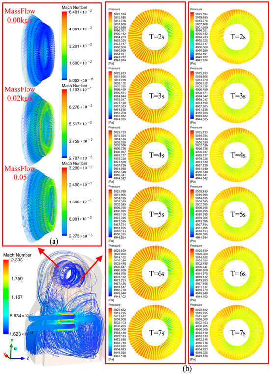
Figure 10.
The Mach number and pressure distribution over the last-stage rotating blade surfaces at different times: (a) Mach number distribution at different outlet mass flow rates; (b) pressure distribution at different times with an outlet mass flow rate of the steam of 0.05 kg/s (left—pressure surface; right—suction surface).
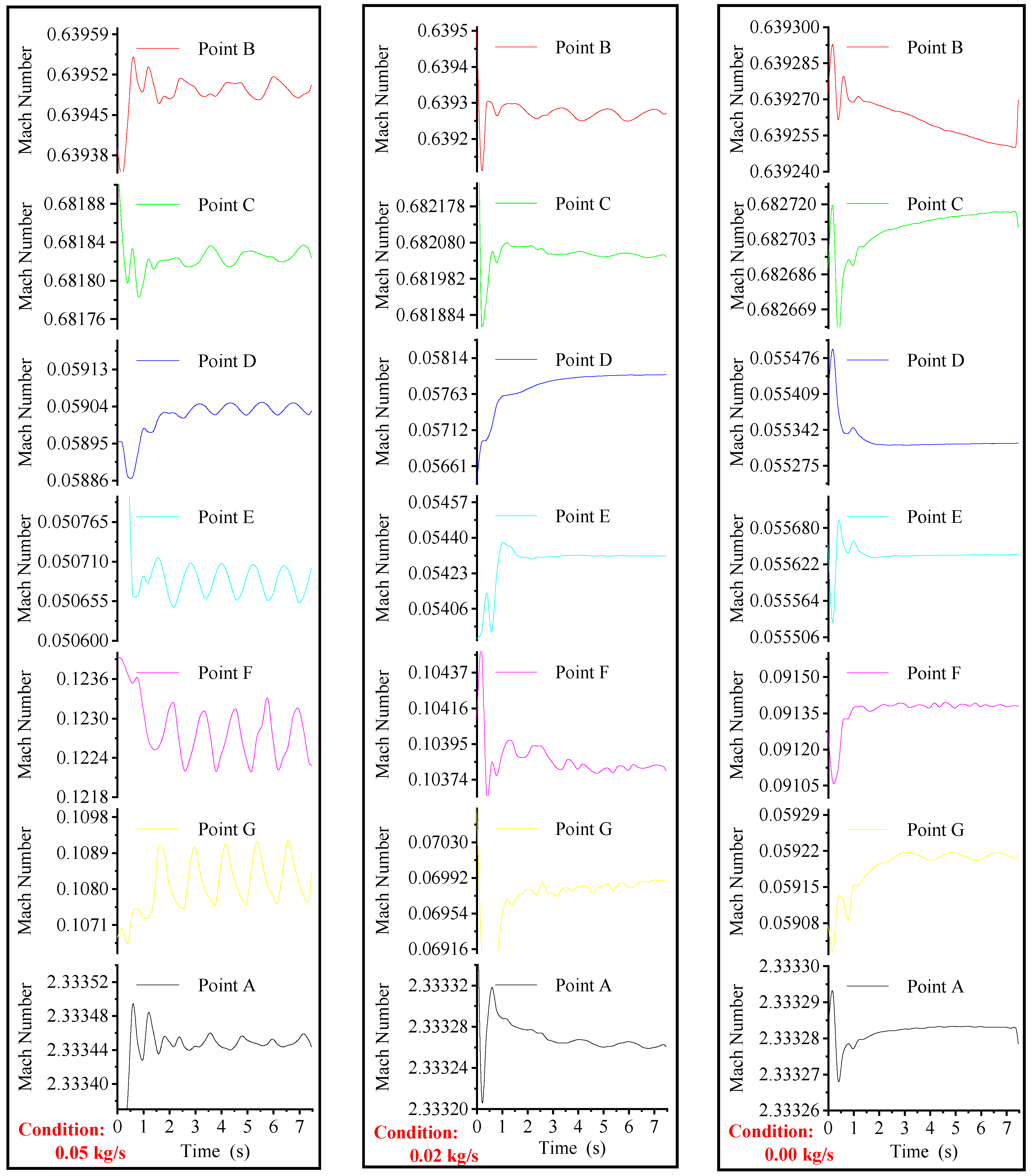
To analyze the effect of the outlet mass flow rate of the steam from the second-last-stage stationary blades on the Mach number distribution at different times quantitatively, seven typical points are selected (see Figure 9). Notably, A, F, and G represent the points with the highest Mach number in the region of the bypass diffusers, in the region of the last-stage blades away from the bypass diffusers, and in the region of the last-stage blades close to the bypass diffusers, respectively.
Figure 11 shows the change in the Mach number at various points over time. After comparing the numerical calculation results, it can be found that when the outlet mass flow rate of the steam from the second-last-stage stationary blades is zero, the Mach number at some points (A, B, C) changes drastically and irregularly over time, while the change in the Mach number at the remaining points is gentle. As the outlet mass flow rate of the steam increases, the regularity of the Mach number of flow, over time, becomes more apparent. Notably, when the outlet mass flow rate of the steam is 0.05 kg/s, the Mach number of the steam at Points D, E, F, and G shows extraordinarily evident cyclic variation.
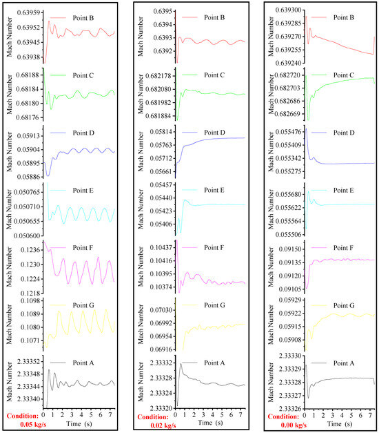
Figure 11.
Mach number variation at various points over time.
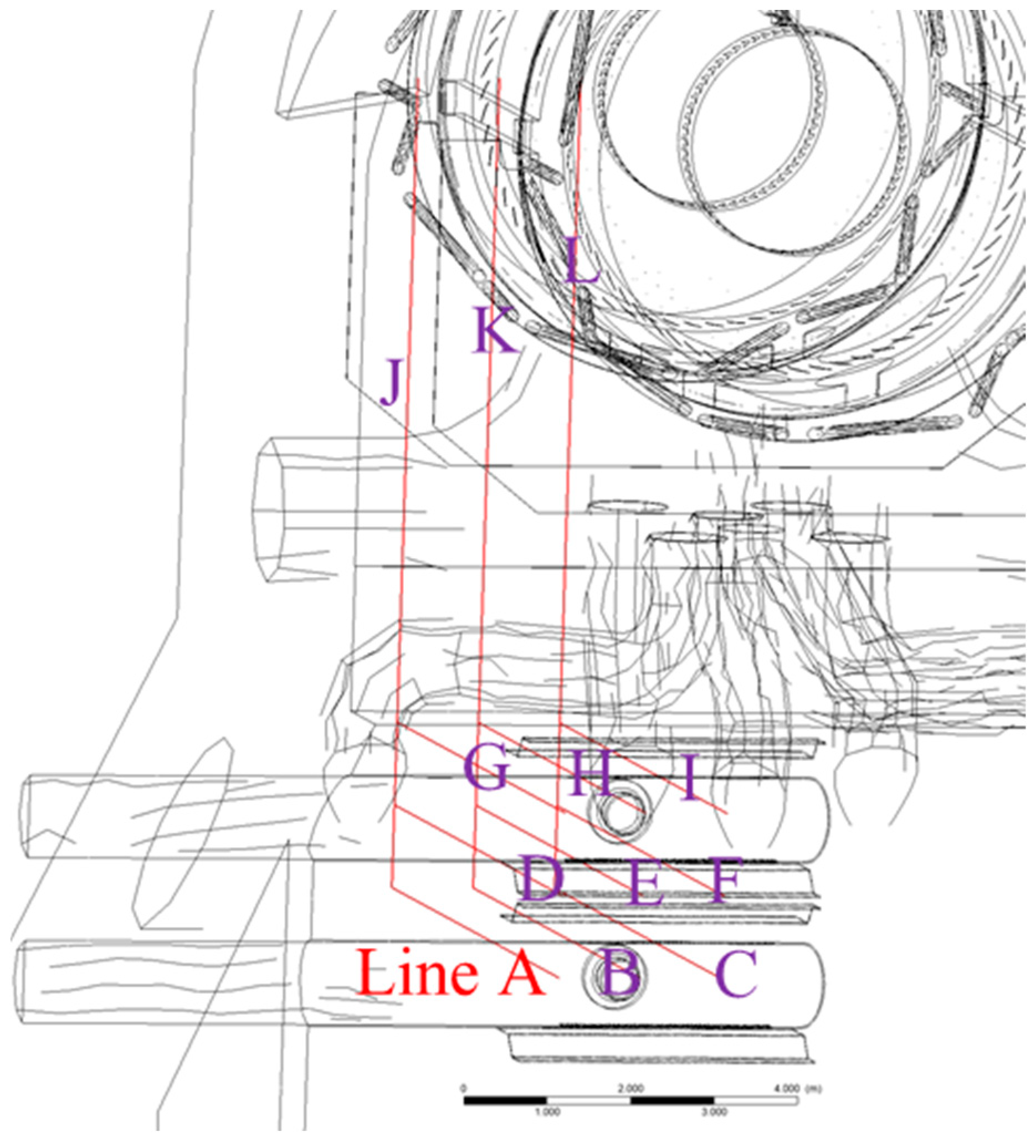
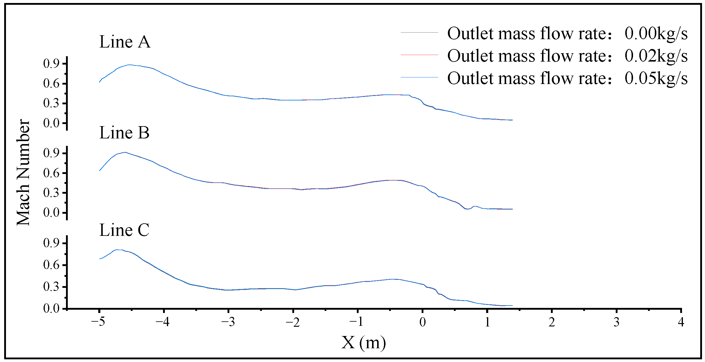
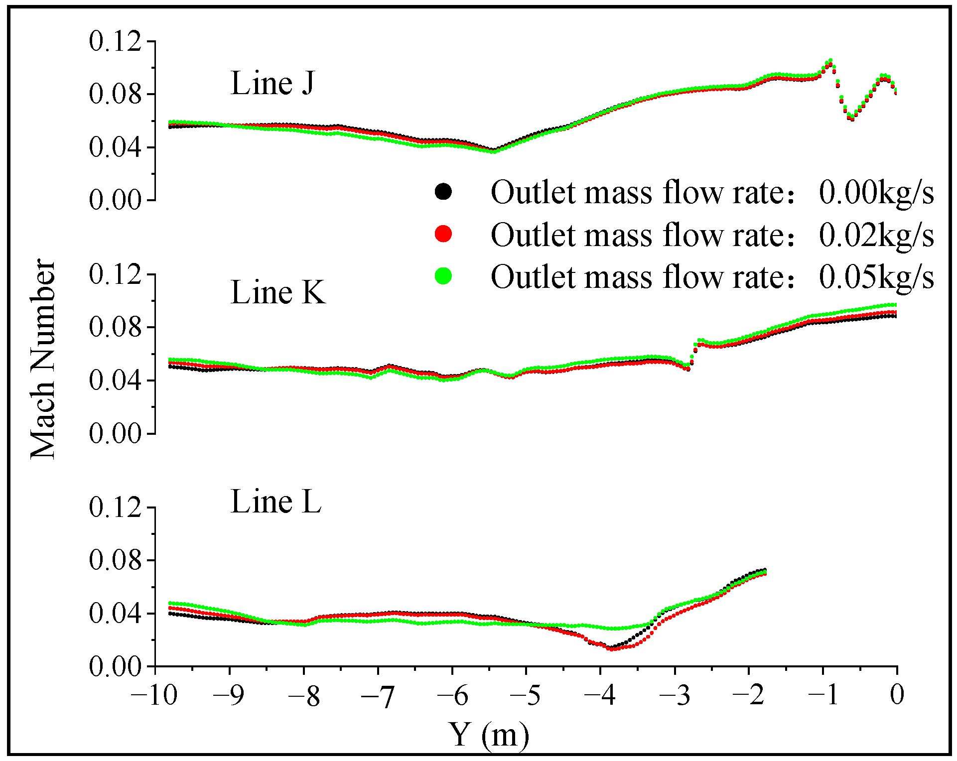
To analyze the effect of the outlet mass flow rate of the steam from the second-last-stage stationary blades on the Mach number distribution in the entire model quantitatively, the points on 12 lines aligned with the direction of the steam flow (X-axis and Y-axis directions) are selected (see Figure 12). Each line is equally divided into 200 points, and the Mach number variations at these points in lines A, B, and C (in the X-axis direction) and lines J, K, and L (in the Y-axis direction) are shown in Figure 13 and Figure 14. Note that the B, C, D, and E points in Figure 9 are crucial points in the horizontal jet flow direction and also serve as endpoints for the monitoring line (lines A and G; see Figure 12). The simulation results show that the maximum Mach number does not change significantly and remains relatively at about 2.333 with different mass flow rates of steam. Furthermore, the change in the Mach number of the flow at the points in the X-axis direction is gentle, while it changes significantly at the points near the pipelines and the low-pressure cylinders. It is noteworthy that the outlet mass flow rate of steam does not alter the Mach number distribution in the X-axis direction.
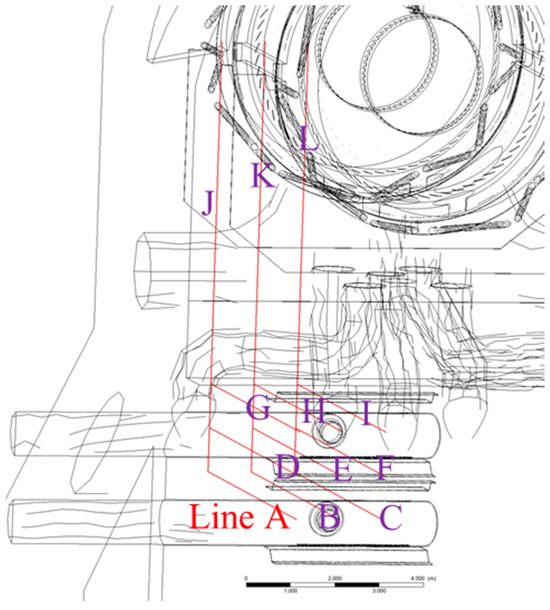
Figure 12.
Locations of the selected lines (A–I are nine lines in the X-axis direction, and J–L are three lines in the Y-axis direction).
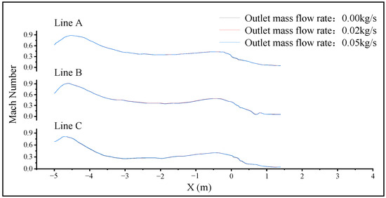
Figure 13.
Mach number distribution along lines A, B, and C.
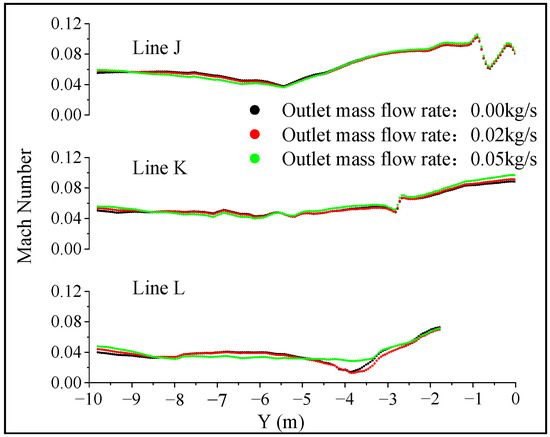
Figure 14.
Mach number distribution along lines J, K, and L.
Fluctuation in the Mach numbers at the points in the Y-axis direction is observed, particularly near the impeller section (at Y = −3.75 m), where the difference in Mach number at three outlet mass flow rates reaches 60%. This suggests that, in comparison to the zero-mass flow rate condition, the non-uniform circumferential distribution of pressure enhances the instability of the flow field near the blades when the outlet mass flow rate of the steam is 0.05 kg/s. This observation further implies that turbulent steam causes disturbances and potentially contributes to the forced vibration of the last-stage rotating blades.
3.2.2. The Transient Characteristics of the Forces Acting on the Last-Stage Rotating Blades
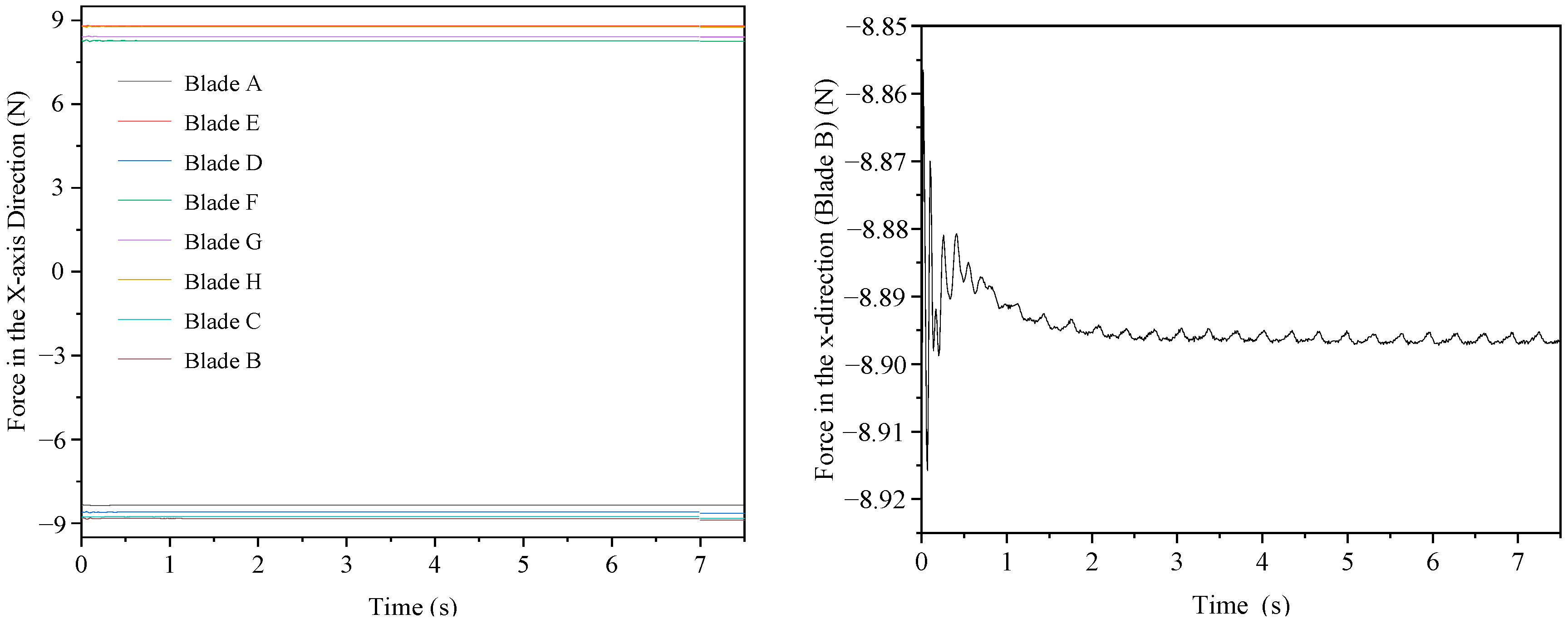
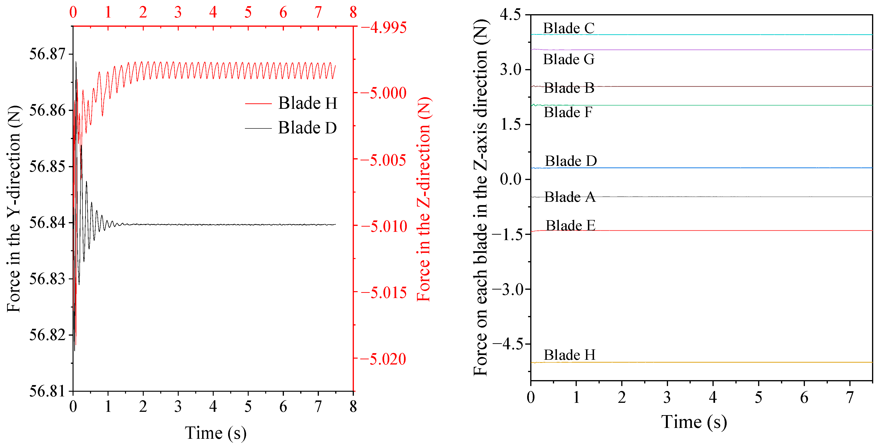
To obtain the change in the forces acting on the last-stage rotating blades, the representative monitoring blades along the Y-axis and Z-axis are established, which is consistent with that during the steady-state simulation process. Under the condition of 0 kg/s mass flow rate of outlet steam, the forces acting on the eight last-stage rotating blades in the X-, Y-, and Z-axes (see Figure 15 and Figure 16) change regularly within 2 to 7.5 s. The forces in the Z-axis direction exhibit the most substantial fluctuations, while the changes in forces in the Y-axis direction are gentle, with the maximum change reaching only 0.408 N. Moreover, among all the monitored blades, blade B can stand the maximum force in the X-axis direction (about 8.895 N), with a negligible variation of only 0.005 N. The results show that the forces acting on the last-stage rotating blades are influenced by their positions. The forces in the X-, Y-, and Z-axis directions are higher on the side distant from the bypass diffusers than on the opposite side.
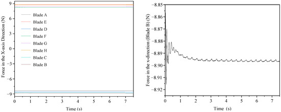
Figure 15.
The change in the forces acting on the blades in the X-axis direction with time (outlet steam mass flow rate: 0 kg/s).
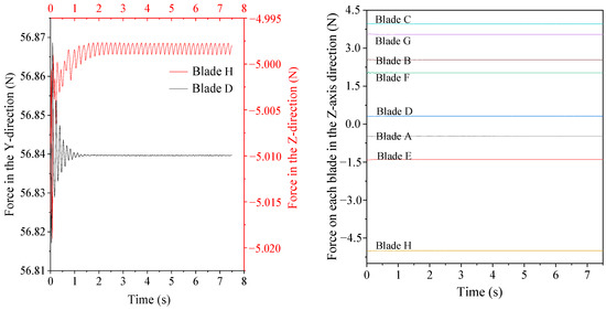
Figure 16.
The change in the forces acting on the blades in the Y and Z directions with time (outlet steam mass flow rate: 0 kg/s).
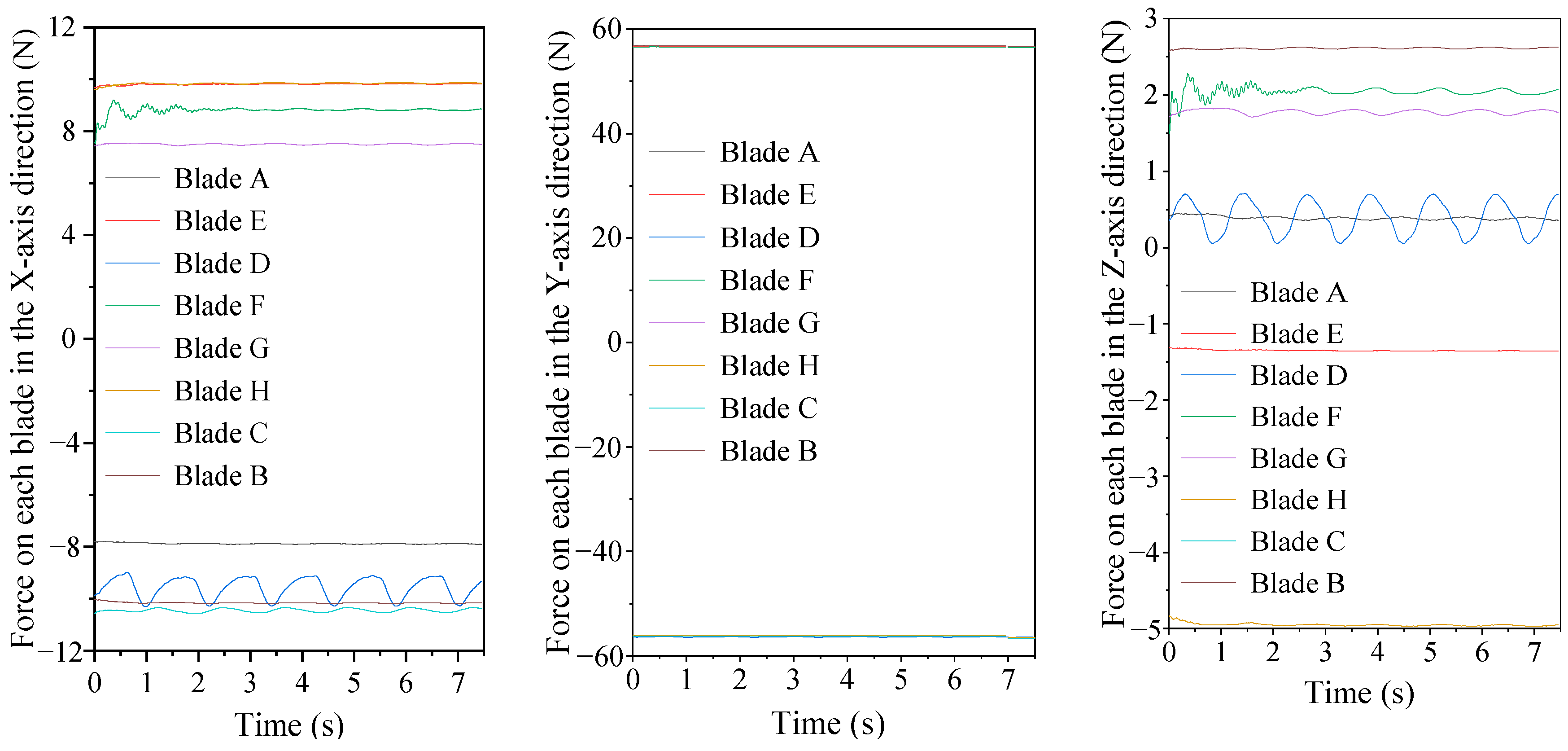
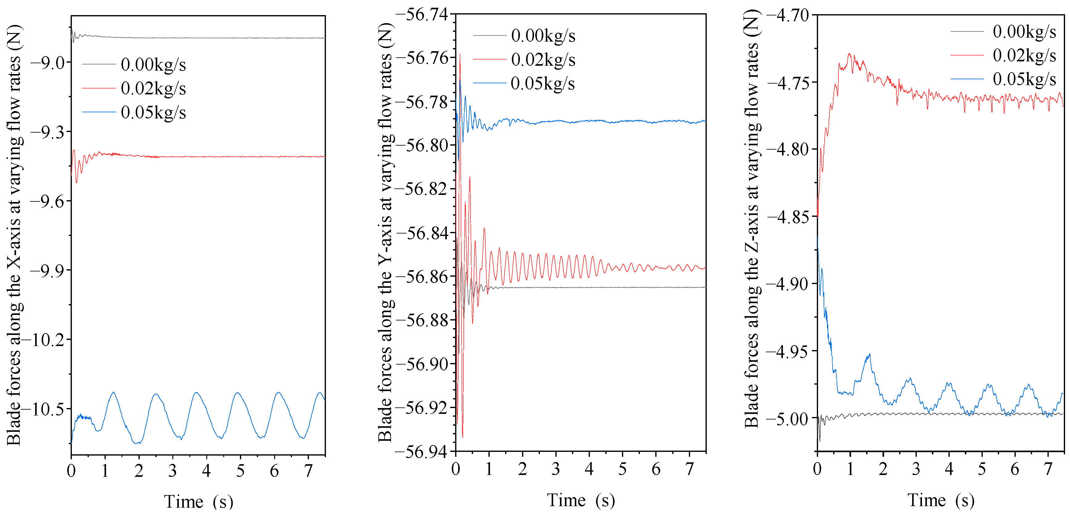
For the condition of 0.05 kg/s outlet steam mass flow rate, the variation in the forces acting, in the X-axis and Z-axis directions, on the last-stage rotating blades over time is shown in Figure 17. The fluctuation in values for the forces acting on certain last-stage rotating blades reaches 1.2 N (X-axis) and 0.6 N (Z-axis), while the corresponding values are 0.005 N and 0.002 N, respectively, under the zero-mass flow rate condition.
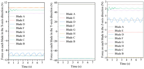
Figure 17.
The change in the forces acting on the blades in the Y and Z directions with time (outlet steam mass flow rate: 0.05 kg/s).
In contrast to the X- and Z-axes, the forces on the last-stage rotating blades in the Y-axis direction remain relatively constant at about 56.8 N. Although the forces acting on the last-stage rotating blades differ across each direction, their change periods are consistently around 1.25 s. When the outlet mass flow rate of the steam is 0.02 kg/s, the change period is approximately 0.75 s. This suggests that the mass flow rate of steam has an influence on the change period of the forces acting on the last-stage rotating blades, with higher mass flow rates corresponding to extended change periods.
Figure 18 shows the maximum force acting on the monitored blades in all directions at different outlet steam mass flow rates. It becomes evident that the forces acting on the last-stage rotating blades vary, and the magnitude of the force fluctuates with time at different steam outlet mass flow rates. Specifically, the forces on the blades in the X- and Y-axes become more robust as the outlet flow rate of the steam increases. However, the force in the Z-axis does not change significantly, and the maximum force in the Z-axis on each blade under the zero-mass flow rate condition exceeds that for other conditions. This may be because the decoupling and reflux of the steam in the low-pressure cylinders under the zero-mass flow rate condition result in a change in the force in the Z-axis.
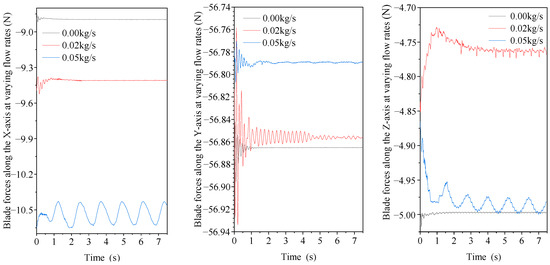
Figure 18.
Forces acting on blades in all directions at different outlet steam mass flow rates.
Based on the analysis above, it can be found that the forces acting on the last-stage rotating blades in different directions change periodically with time, and the magnitude and period of the variation correlate with the outlet mass flow rate of steam from the second-last-stage stationary blades. The forced vibration of the blades due to the disturbance of turbulent steam flow from the bypass diffusers may cause the local detachment and cracking of the lacing lug of the last-stage blades. However, the numerical simulation presented in the present paper needs to be further verified by experimental data. It is still necessary to install a blade vibration monitoring system on the last-stage blades of the operating unit, which can be used to monitor the vibration of the last-stage blades at different speeds and operating conditions, further clarifying the operating conditions where abnormal vibration occurs.
4. Conclusions
The steam discharged from bypass diffusers with a high flow velocity may reverse into the space of low-pressure cylinders, which may cause forced vibration and even the cracking of turbine blades. A full-scale CFD calculation model including bypass diffusers, last-stage and the second-last-stage blades, and steam extraction pipelines was constructed. The fluid dynamic characteristics of the supersonic steam flow discharged from the bypass diffuser and the effect of the steam on last-stage blades were analyzed comprehensively via both steady and transient methods. The steady-state simulation results reveal that the steam at the orifice outlet of the bypass diffusers presents a typical jet flow, with some steam flowing back into the space of last-stage blades through the exhaust of low-pressure cylinders. This results in a notable disturbance to the last-stage rotating blades, characterized by a non-uniform circumferential pressure distribution. The forces acting on the last-stage rotating blades in the X-, Y-, and Z-axis directions are different, with the force in the Y-axis direction being the highest. The transient numerical simulation results reveal that the outlet mass flow rate of the steam from the second-last-stage stationary blades has a significant effect on both the Mach number distribution, and the surface forces acting on the last-stage rotating blades. With an increase in the outlet mass flow rate of the reverse steam, the instability of the flow field escalates. The difference in the Mach number at the same position can reach as high as 60% or more under different operating conditions. Moreover, the forces acting on the last-stage rotating blades in different directions change periodically with time, and the magnitude and period of the variation correlate with the outlet mass flow rate of the steam from the second-last-stage stationary blades.
Author Contributions
Conceptualization, F.C. and Z.Z.; methodology, K.B.; software, H.L.; validation, F.C., Z.Z., and M.L.; formal analysis, M.L.; investigation, H.L. and M.L.; data curation, F.C. and Z.Z.; writing—original draft preparation, H.L.; writing—review and editing, M.L.; supervision, F.C. and M.L.; project administration, F.C., Z.Z., and K.B.; funding acquisition, Z.Z. All authors have read and agreed to the published version of the manuscript.
Funding
This research was funded by the fund of State Key Laboratory of Clean and Efficient Turbomachinery Power Equipment, grant number “DEC8300CG202210286EE280291”.
Data Availability Statement
Data are contained within the article.
Acknowledgments
The authors gratefully acknowledge the financial support of the State Key Laboratory of Clean and Efficient Turbomachinery Power Equipment.
Conflicts of Interest
Authors Fang Chen, Zhuhai Zhong and Kunlun Bai were employed by the company Dongfang Electric Corporation Dongfang Turbine Co., Ltd. The remaining authors declare that the research was conducted in the absence of any commercial or financial relationships that could be construed as a potential conflict of interest. The company had no role in the design of the study; in the collection, analyses, or interpretation of data; in the writing of the manuscript, or in the decision to publish the results.
References
- Akhtar, S.Z. Proper steam bypass system design avoids steam turbine overheating. Power Eng. 2003, 107, 44–49. [Google Scholar]
- Eaton, R.H.; Blessman, E.R.; Schoonover, K.G. Design considerations and operation of condenser bypass systems in combined cycle power plants: Part 2. In Proceedings of the ASME 2004 Power Conference, Baltimore, MD, USA, 30 March–1 April 2004; Volume 41626, pp. 263–268. [Google Scholar]
- Eaton, R.H.; Blessman, E.R.; Schoonover, K.G. Design considerations and operation of condenser bypass systems in combined cycle power p: Part 1. In Proceedings of the ASME 2004 Power Conference, Baltimore, MD, USA, 30 March–1 April 2004; Volume 41626, pp. 255–262. [Google Scholar]
- Lu, C.; Yang, J.; Zhang, Q. Pressure Transient Analysis on the Condenser of the HPR1000 Nuclear Power Unit. Energies 2024, 17, 1210. [Google Scholar] [CrossRef]
- Zu, S.; Chen, J.; Che, Y.; Wang, G.; Wu, Z.; Wang, J.; Zhu, C.; Zhang, Q.; Dong, B. Research on steam flow excited vibration of nuclear power condenser based on full three-dimensional numerical simulation technology. AIP Adv. 2022, 12, 035015. [Google Scholar] [CrossRef]
- Heat Exchange Institute, Inc. Standards for Steam Surface Condensers, 12th ed.; HEI-2629, Heat Exchange Institute: Cleveland, OH, USA, 2018. [Google Scholar]
- Sebald, J.F.; Phillips, N.A.; Haman, L.L. Haman. Recommended Guidelines for the Admission of High-Energy Fluids to Steam Surface Condensers; EPRI-CS-2251; Electric Power Research Institute: Palo Alto, CA, USA, 1982. [Google Scholar]
- Nightingale, D.M. Design guidelines for the safe operation of steam surface condenser turbine bypass on combined cycle power plants. In Proceedings of the ASME Power Conference, Charlotte, NC, USA, 26–30 June 2017. [Google Scholar]
- Connors, H.J., Jr. Fluidelastic vibration of heat exchanger tube arrays. J. Mech. Des. 1978, 100, 347–353. [Google Scholar] [CrossRef]
- Wu, F.; Han, A.; Jiang, W.; Yue, Y.; Xie, D. A biomimetic design of steam turbine blade to improve aerodynamic performance. Int. J. Therm. Sci. 2022, 181, 107782. [Google Scholar] [CrossRef]
- Menter, F.R. Two-equation eddy-viscosity turbulence models for engineering applications. AIAA J. 1994, 32, 1598–1605. [Google Scholar] [CrossRef]
- Bardina, J.E.; Huang, P.G.; Coakley, T.J. Turbulence Modeling Validation, Testing, and Development. In NASA Technical Memorandum; Ames Research Center: Moffett Field, CA, USA, 1997. [Google Scholar]
- Shabani, S.; Majkut, M.; Dykas, S.; Smołka, K.; Lakzian, E. An investigation comparing various numerical approaches for simulating the behavior of condensing flows in steam nozzles and turbine cascades. Eng. Anal. Bound. Elem. 2024, 158, 364–374. [Google Scholar] [CrossRef]
- Wang, W.; Gao, J.; Shi, X.; Xu, L. Cooling performance analysis of steam cooled gas turbine nozzle guide vane. Int. J. Heat Mass Transf. 2013, 62, 668–679. [Google Scholar] [CrossRef]
- Win Naung, S.; Rahmati, M.; Farokhi, H. Direct Numerical Simulation of Interaction between Transient Flow and Blade Structure in a Modern Low-Pressure Turbine. Int. J. Mech. Sci. 2021, 192, 106104. [Google Scholar] [CrossRef]
- Rajesh, B.C.; Hensh, P.K. CFD analysis of a single stage intermediate pressure steam turbine. Mater. Today Proc. 2021, 45, 58–64. [Google Scholar] [CrossRef]
- Fowler, J. Factors Affecting the Design of Turbine-Condenser Connections. J. Eng. Power. 1977, 99, 429–436. [Google Scholar] [CrossRef]
- Nagamatsu, H.; Sheer, R.J. Subsonic and supersonic jets and supersonic suppressor characteristics. In Proceedings of the Aeroacoustics Conference, Seattle, WA, USA, 15–17 October 1973; p. 999. [Google Scholar]
- Yang, S.; Du, W.; Luo, L.; Wang, S. Effects of flow coefficient on turbine aerodynamic performance and loss characteristics. Int. J. Aerosp. Eng. 2022, 2022, 4633333. [Google Scholar] [CrossRef]


Disclaimer/Publisher’s Note: The statements, opinions and data contained in all publications are solely those of the individual author(s) and contributor(s) and not of MDPI and/or the editor(s). MDPI and/or the editor(s) disclaim responsibility for any injury to people or property resulting from any ideas, methods, instructions or products referred to in the content. |
© 2024 by the authors. Licensee MDPI, Basel, Switzerland. This article is an open access article distributed under the terms and conditions of the Creative Commons Attribution (CC BY) license (https://creativecommons.org/licenses/by/4.0/).