Article

Three-Dimensional Physical Test Study on the Overburden Breaking Behavior of Non-Penetrating Pre-Splitting in Small-Coal-Pillar Roadway Roofs

1
School of General Education, Shanxi Institute of Science and Technology, Jincheng 048000, China
2
School of Mechanics and Civil Engineering, China University of Mining and Technology, Xuzhou 221116, China
*
Authors to whom correspondence should be addressed.
Processes 2024, 12(7), 1491; https://doi.org/10.3390/pr12071491
Submission received: 30 June 2024 / Revised: 15 July 2024 / Accepted: 15 July 2024 / Published: 16 July 2024

Abstract

:
In longwall coal mining, significant deformation of small-pillar roadways presents challenges for the safe and efficient retreat of mining panels. Non-penetrating directional pre-splitting alters the roof structure of these roadways and effectively manages their stability under high stress during mining operations. In this study, a three-dimensional experimental model for the non-penetrating pre-splitting of small-coal-pillar roadway roofs was established, the apparent resistivity change in the rock layer during mining of the working face was determined, the propagation law of high-frequency electromagnetic waves in the overlying rock was studied, and the stress distribution law of the surrounding rock was investigated. After non-penetrating pre-splitting in the roof, the apparent resistivity change rate of the overlying rock increased and the electromagnetic waveform exhibited scattering and diffraction, forming a short cantilever beam. After mining, the stress in the adjacent mining panel gateway reduced, resulting in a pressure relief effect on the surrounding rock. These findings were further validated through field application, where the overall deformation of the roadway was reduced by 57%. The research results shed light on the management of roof control in small-coal-pillar roadways and the rational determination of non-penetrating pre-splitting parameters.

1. Introduction

Small-coal-pillar protection roadways [1] are commonly utilized in the layout of longwall mining panels [2,3]. However, they face significant deformation and safety risks due to multiple dynamic pressures from both roadway excavation and the working face of the mine [4]. The traditional strengthening support method [5] cannot sufficiently ensure safe and efficient production. Pressure relief technology for non-penetrating directional pre-splitting blasting in cases where there is a deep hole ahead [6] induces non-penetrating cracks in the roof of the small-coal-pillar roadway (Figure 1), thereby optimizing its roof structure, altering the stress distribution of and mitigating pressure in surrounding rock, and managing the stability of the high-stress small-coal-pillar roadway during mining operations.
Extensive research has been conducted on the stability of small-coal-pillar roadways and pre-splitting pressure relief technology. Most scholars have focused on the factors influencing the stability of the roadway, including groundwater [7,8], roof and floor lithology, and support [9], and investigated the deformation characteristics [10], stress distribution [11], and plastic zone failure [12] of the surrounding rock. Additionally, the proposed supporting measures for small-coal-pillar roadways include high-strength bolt–cable support [13,14], grouting reinforcement [15], and pre-splitting pressure relief technology [16]. In the field of pre-splitting pressure relief technology in small-coal-pillar roadway roofs, scholars have primarily focused on the formation of pre-splitting cracks [17], the impact of these cracks on surrounding rock deformation, and the optimization of pre-splitting parameters [18]. There is limited research available on safeguarding small-coal-pillar roadways through prefabricated non-penetrating cracks.
The utilization of three-dimensional physical simulation tests [19,20,21,22] is an essential approach for investigating the migration and evolution patterns of overlying rock in coal mines [23]. Geological radar [24] and electrical monitoring [25,26] can capture information pertaining to rock collapse within three-dimensional similarity models. By considering the propagation characteristics of electromagnetic waves [27] and the changes in apparent resistivity monitored using electrical methods [28,29], it becomes feasible to monitor the caving pattern inside these models. There is limited research using three-dimensional physical simulation tests to study rock collapse in small-coal-pillar roadways protected using roof pre-splitting.
Studying non-penetrating directional pre-splitting relief using three-dimensional physical simulation tests is of significant importance in protecting small-coal-pillar roadways. This paper employs a three-dimensional physical simulation test method to depict the breaking of overlying rock in a three-dimensional model by integrating rock displacement, apparent resistivity change, and an electromagnetic wave propagation waveform. It investigates the influence of non-penetrating directional pre-splitting on the migration rule of overlying rock and the broken structure, thus providing a basis for the rational determination of non-penetrating directional pre-splitting parameters and the control of small-coal-pillar roadway roofs.

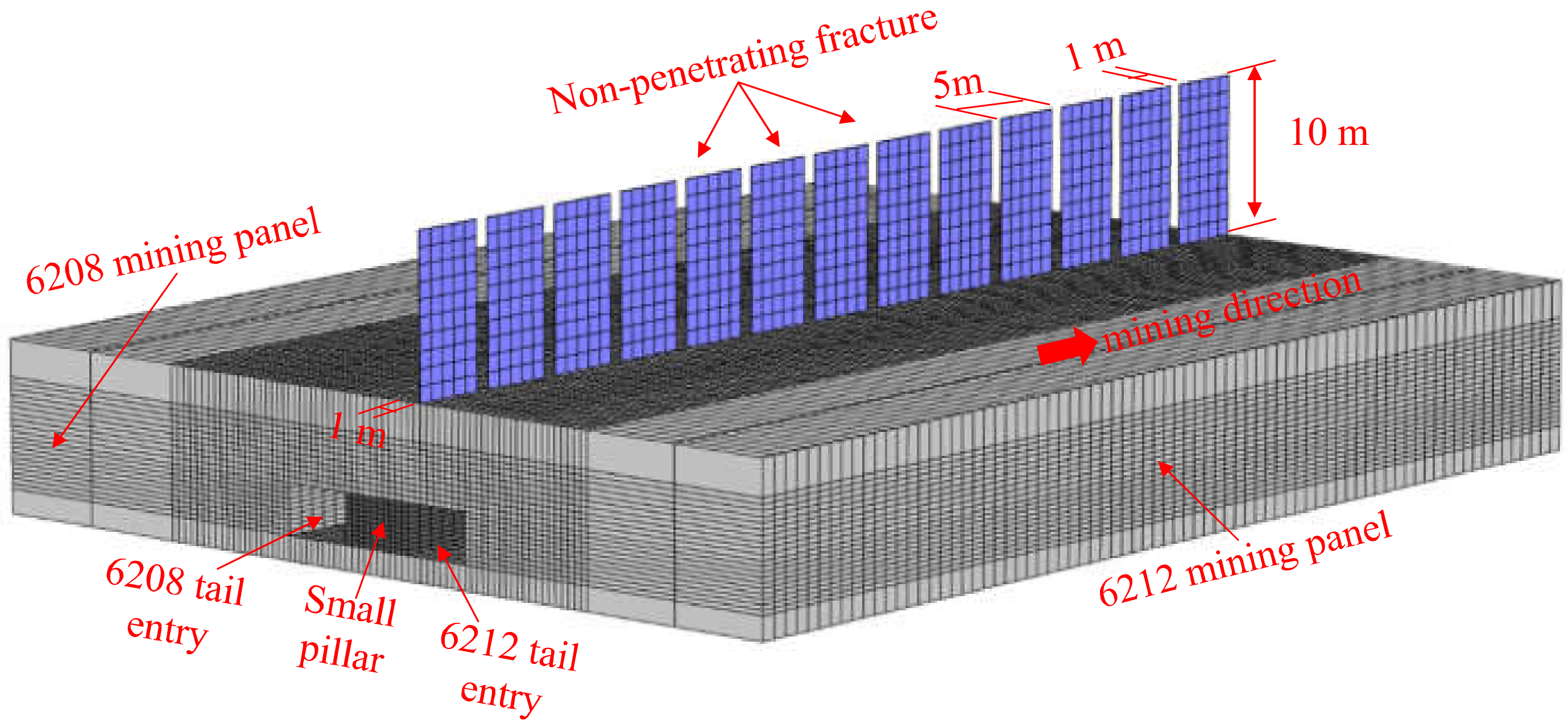
2. Three-Dimensional Physical Simulation Test Parameter Design and Test Scheme

2.1. Design of Physical Simulation Test Parameters

The dimensions of the three-dimensional physical simulation test device are length × width × height = 2320 mm × 1200 mm × 600 mm. Figure 2 shows the test scheme and the arrangement of the measurement points. In order to minimize the impact of model boundaries, a specified boundary area was delineated around the model, with an experimental zone established beyond this to effectively counteract inherent boundary effects in the physical model. The model was divided into three areas—(I) penetrating pre-splitting; (II) non-penetrating pre-splitting; and (III) no pre-splitting—and the influence of prefabricated fractures on the overburden migration caving rule was studied.
In the physical simulation test, the geometry ratio between the model and prototype was Cl = 1/80; the width and height of the roadway in the model were 56.3 mm and 40.0 mm, respectively, and the width of the small coal pillar was 62.5 mm. The average density of the prototype rock was 2500 kg/m3, the average density of the similarity model material was 1500 kg/m3, the bulk density ratio was Cr = 3/5, and the stress similarity ratio was Cσ = Cl × Cr = 1/133. For the physical simulation test materials, river sand was chosen as the aggregate, light calcium carbonate and gypsum as the cement, mica powder as the layered material, and water as an auxiliary. The physical model was laid out layer by layer according to the design ratio. The simulated stratification and intensity matching for the similar materials used for testing are shown in Table 1.

2.2. The Physical Simulation Test Scheme

The roof cracks were prefabricated by inserting iron sheets. The height of the roof fracture in zones I and II was 103.5 mm. The length of the prefabricated penetrating fracture in the roof of zone I was 600 mm. For the prefabricated non-penetrating fracture in the roof of zone II, the fracture length-to-fracture spacing ratio was 5:1, with 62.5 mm fracture length and 12.5 mm fracture spacing. The coal seams were simulated using a foam board, and 10 cm of coal was mined at a time. Figure 3 shows the three-dimensional physical test model, and Figure 4 shows the mining process of the model. During the mining, the suspended steel I-beam bolts at the bottom of the test device were loosened; then, the foam plate was removed from the bottom and the bolts were tightened again.
In the model, a multi-point displacement meter, a pressure box, and an electrode plate were arranged to monitor the stress on the surrounding rock and the cave-in of the overlying rock at different stages of mining. The arrangement of the measurement points and the data acquisition of the three-dimensional similarity model test are shown in Figure 5.
The specific arrangement of the monitoring points for the three-dimensional physical test model was as follows:
(1)
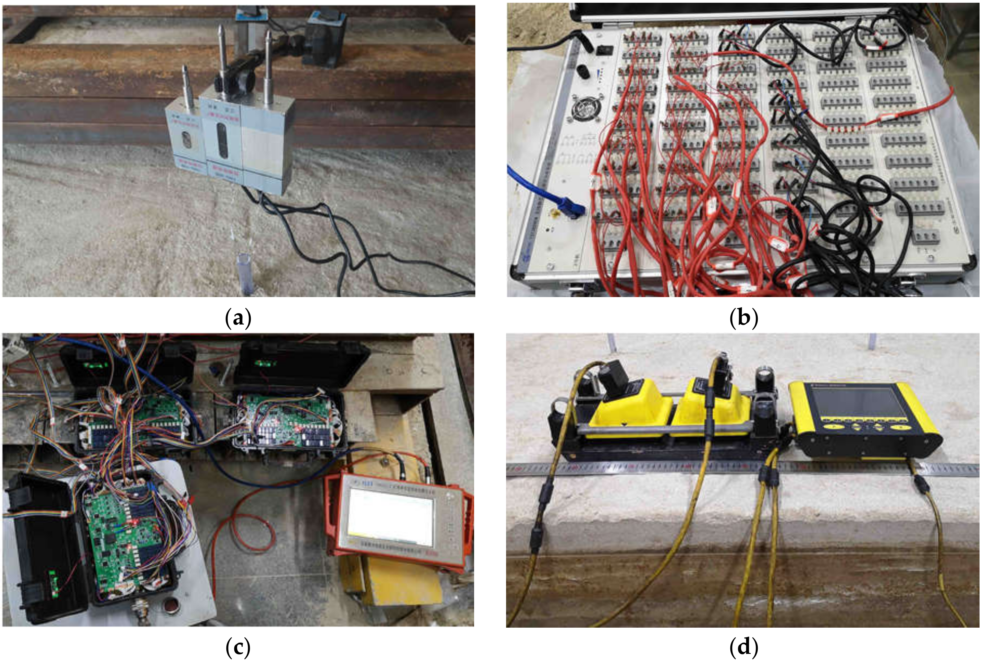
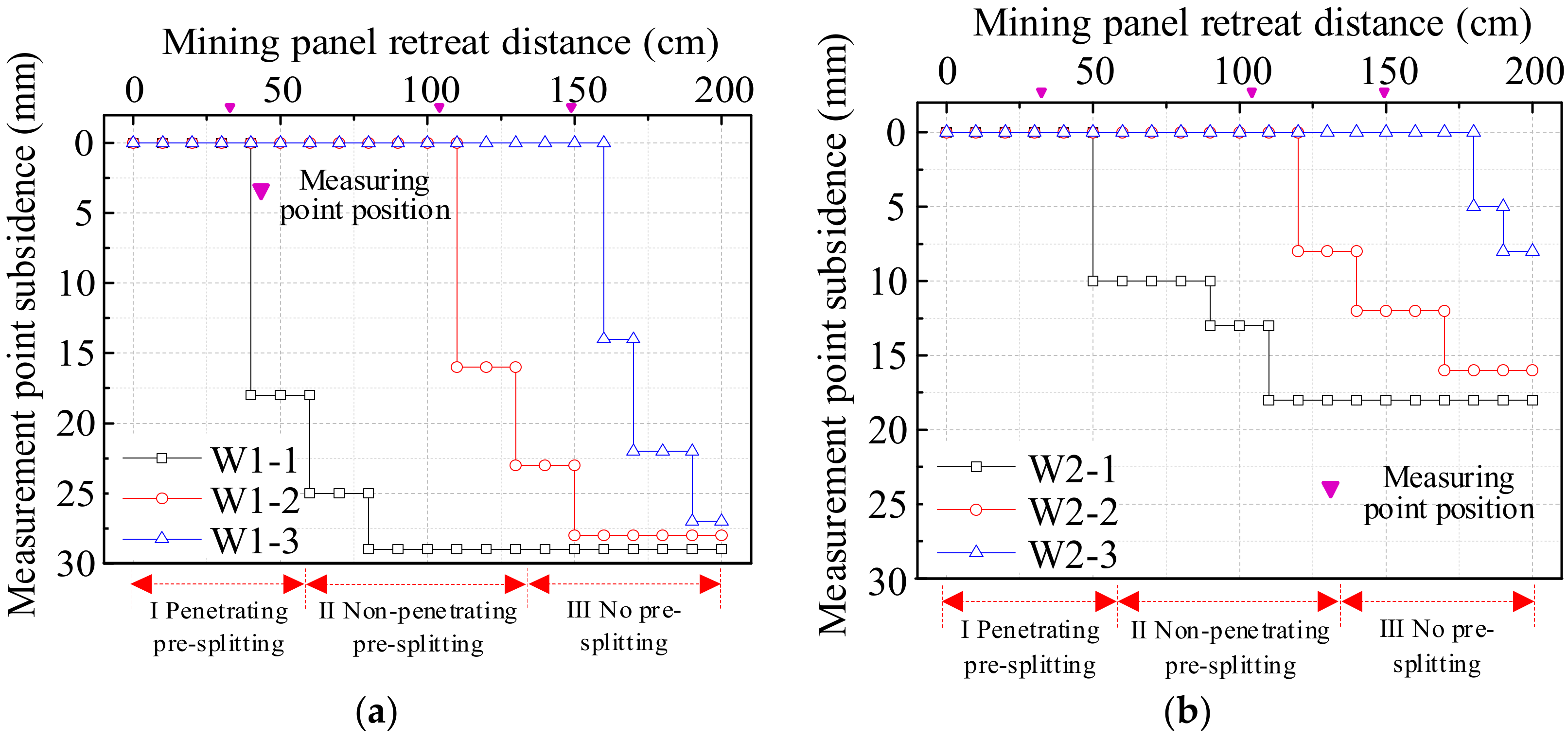
Three multi-point displacement measuring stations were arranged in areas I, II, and III, respectively, and three internal displacement measuring points were set up in each measuring station. The interior displacement measurement points of the first layer were located 94.1 mm away from the coal seam roof in the main roof rock layer and were numbered W1-1 to W1-3. The measured internal displacement points of the second layer were 266.9 mm away from the coal seam roof and were numbered W2-1 to W2-3. The measurement points for the internal displacement in the third layer were 408.2 mm away from the coal seam roof and were numbered W3-1 to W3-3. The displacement of the strata within the model was monitored, and the effect of roof cracks on the displacement of the overlying rock was investigated. The displacement monitoring of rock strata inside the model is shown in Figure 5a. A strain instrument was used to continuously collect strain data during the test and obtain the displacement of rock strata at different levels.
(2)
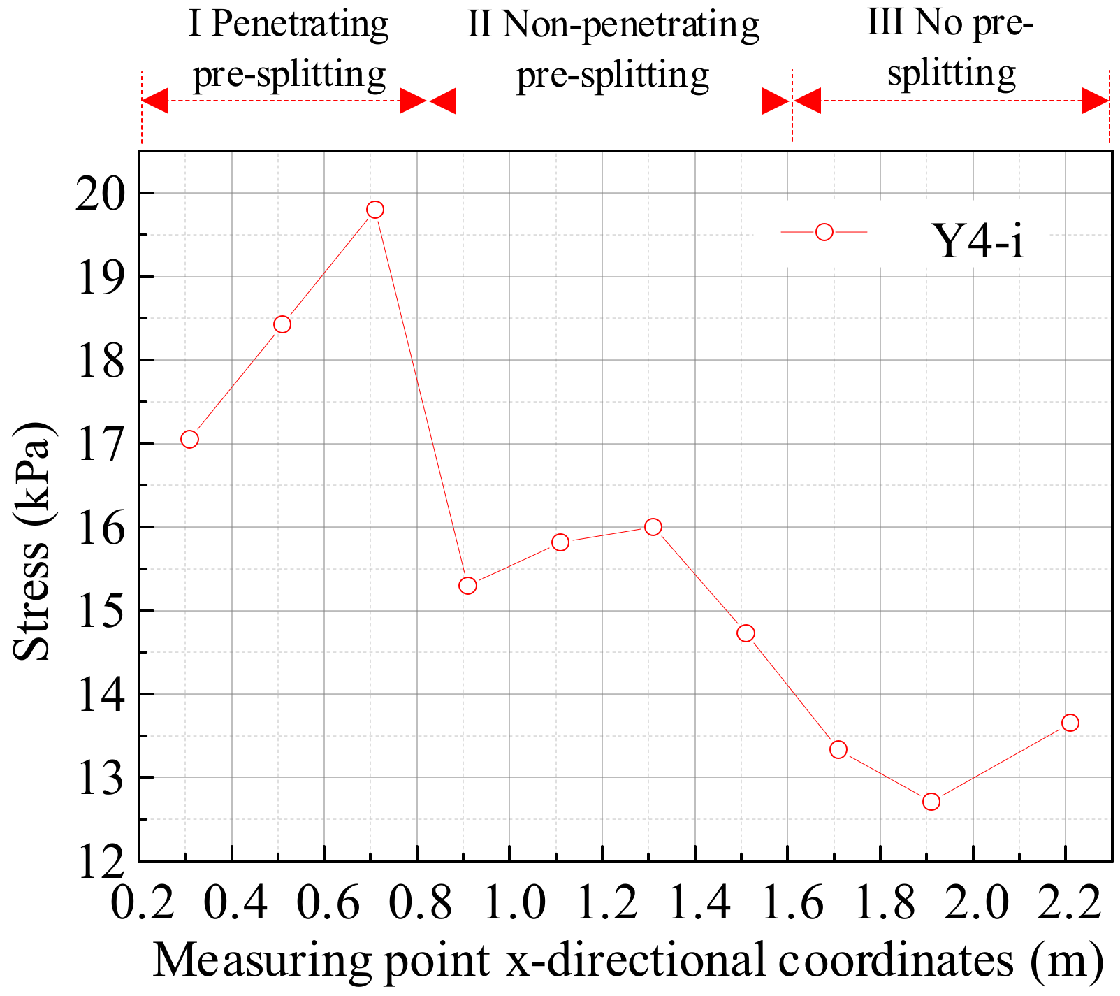
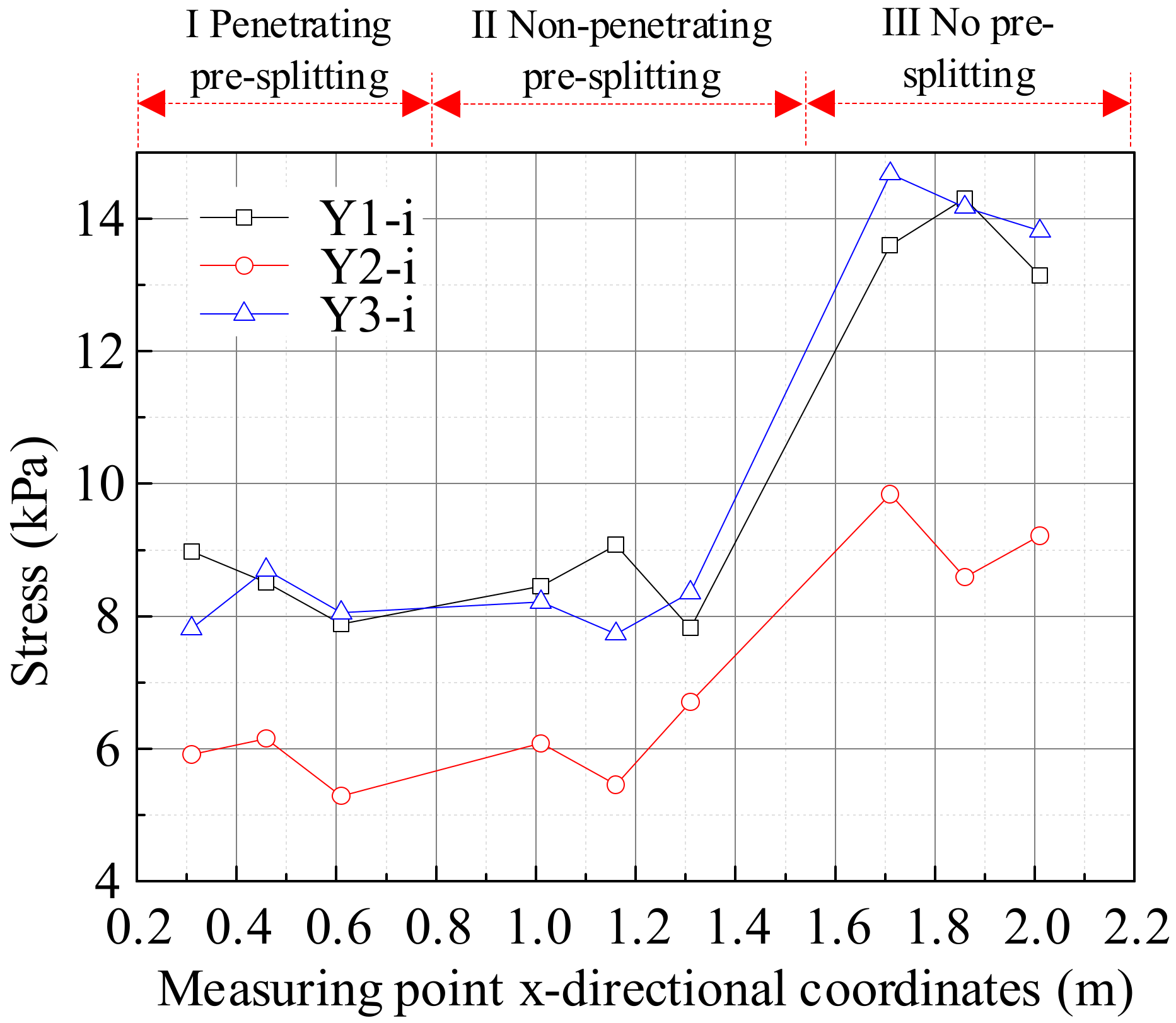
Nine pressure measurement points were arranged on the side of the solid coal wall and on the roof of the adjacent mining panel, respectively. The measuring points were numbered Y1-1–Y1-9 and Y2-1–Y2-9, respectively, to monitor the pressure in the solid coal wall and the roof of the adjacent mining panel after mining of areas I, II, and III. Nine pressure measurement points, numbered Y3-1 to Y3-9, were placed on the small coal pillar to monitor changes in its pressure during the mining process of the working face. A total of 10 pressure measurement points, numbered Y4-1 to Y4-10, were arranged on the gateway roof of the mining panel to monitor the variation in its leading stress during mining. As shown in Figure 5b, a wireless static strain gauge was used to continuously collect strain data of the pressure box during the test.
(3)
The electrodes were arranged in regions I, II, and III, and three apparent resistivity measuring lines were set, numbered D1~D3. Two apparent resistivity measurement lines were set in the forward direction of the working face. These measurement lines were numbered D4 and D5, with D4 aligned directly above the crack in the roof. As shown in Figure 5c, an intrinsic safety seismograph for mines was used to collect the electrical parameters of the measuring lines in areas I, II, and III, and the apparent resistivity of the measuring lines was calculated. The fracture development and collapse laws of the formation were determined using the change rate of the apparent resistivity in different mining areas.
(4)
A geological radar survey line was set in the advancing direction of the working face, numbered L1. Geological radar survey lines were set up in areas I, II, and III, and numbered L2~L4. A pulse geodetic radar with a 1000 MHz antenna was used for detection. As shown in Figure 5d, when mining in different areas, the propagation waveform of electromagnetic waves in the model was monitored using the geological radar, and the development of rock cracks was determined by the change in this waveform.

3. Results and Discussion

During the process of mining the three-dimensional physical model, we conducted an analysis of the cave’s morphology, apparent resistivity change rate, and electromagnetic wave propagation path in various regions. Furthermore, we examined the stress distribution of the surrounding rock in the small-coal-pillar roadway and elucidated the impact of the prefabricated cracks in the roof on the fracture structure and the stress distribution of the overburden.

3.1. Overburden Caving Structure in the Process of the Mining Panel Retreating

After the completion of mining, the overlying rock underwent fracturing to form an O-X-shaped spatial structure, with the rock mass in the strike and dip sections exhibiting a balanced structural state resembling that of a “cantilever beam” and a “masonry beam”. Figure 6 depicts a spatial map illustrating the fractures in the high- and low-key strata following the completion of mining in the three-dimensional model, and Figure 7 shows the top-caving morphology of the model. The following were observed, as depicted in Figure 6 and Figure 7:
(1)
The fracture pattern of the low-lying key rock strata exhibited a “vertical O-X shape”, attributed to the periodic collapse of the low-lying key rock strata, which occurred at intervals shorter than the length of the working face. As the working face advanced, these collapses resulted in the formation of a “vertical O-X shape” fracture structure.
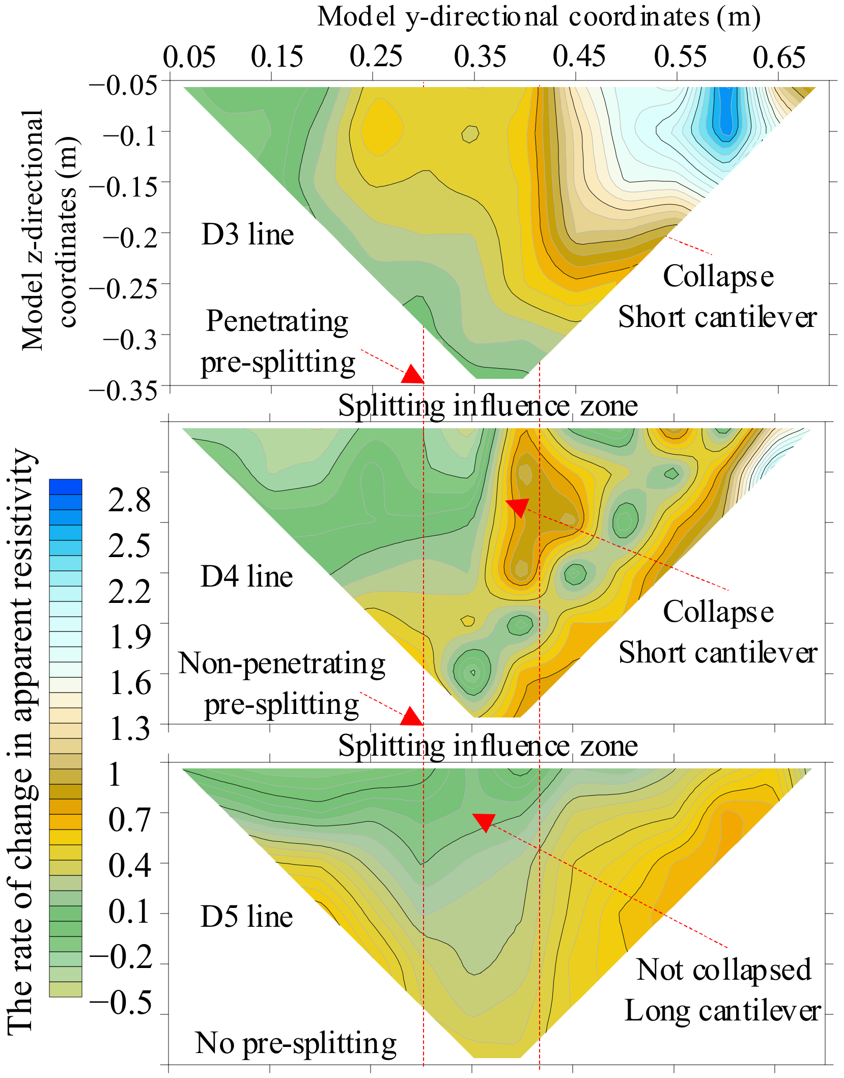
(2)
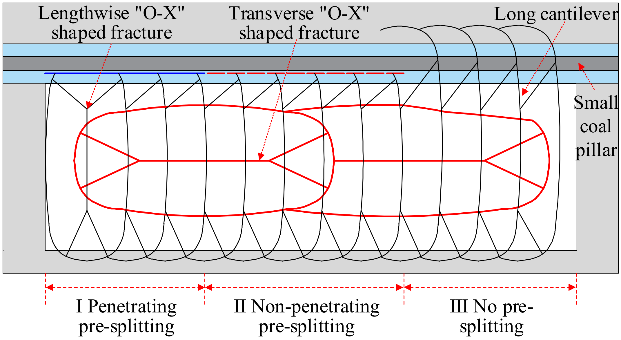
The prefabricated fractures in the mining panel gateway roof altered the roof structure, resulting in changes in the shape and fracture location of the triangular plates within the underlying rock formation. The fracture line of the triangle plate became aligned with the cutting line, positioning its fracture point within the roadway roof and resulting in a balanced “short cantilever beam” and “masonry beam” structure. In contrast, when the roof had no prefabricated fractures, the fracture line of the triangle plate formed an arc, with its fracture position located on an adjacent mining panel, resulting in a balanced “long cantilever beam” structure. As mining progresses, these long cantilevers break, rotate, and subside, causing significant stress on the small-coal-pillar roadway near the adjacent mining panel that is challenging to maintain.
(3)
When prefabricated fractures were applied to the roof, the “short cantilever beam” did not rotate as the mining panel retreated, and the additional load of the roof was small. This resulted in less pressure on the small coal pillar and the adjacent mining panel gateway, thereby safeguarding the adjacent gateway. The hinge point of the “masonry beam” was located in the roadway, and its stability significantly impacted roadway maintenance, increasing the difficulty of maintaining the advancing support section of the roadway and the end of the mining panel. The prefabricated non-penetrating fractures in the roof ensured a secure connection within the roadway’s roof structure, providing inherent stability and ensuring overall structural integrity. Following the mining operations, these non-penetrating fractures collapsed into each other, allowing for delayed roof cutting behind the working face.
(4)
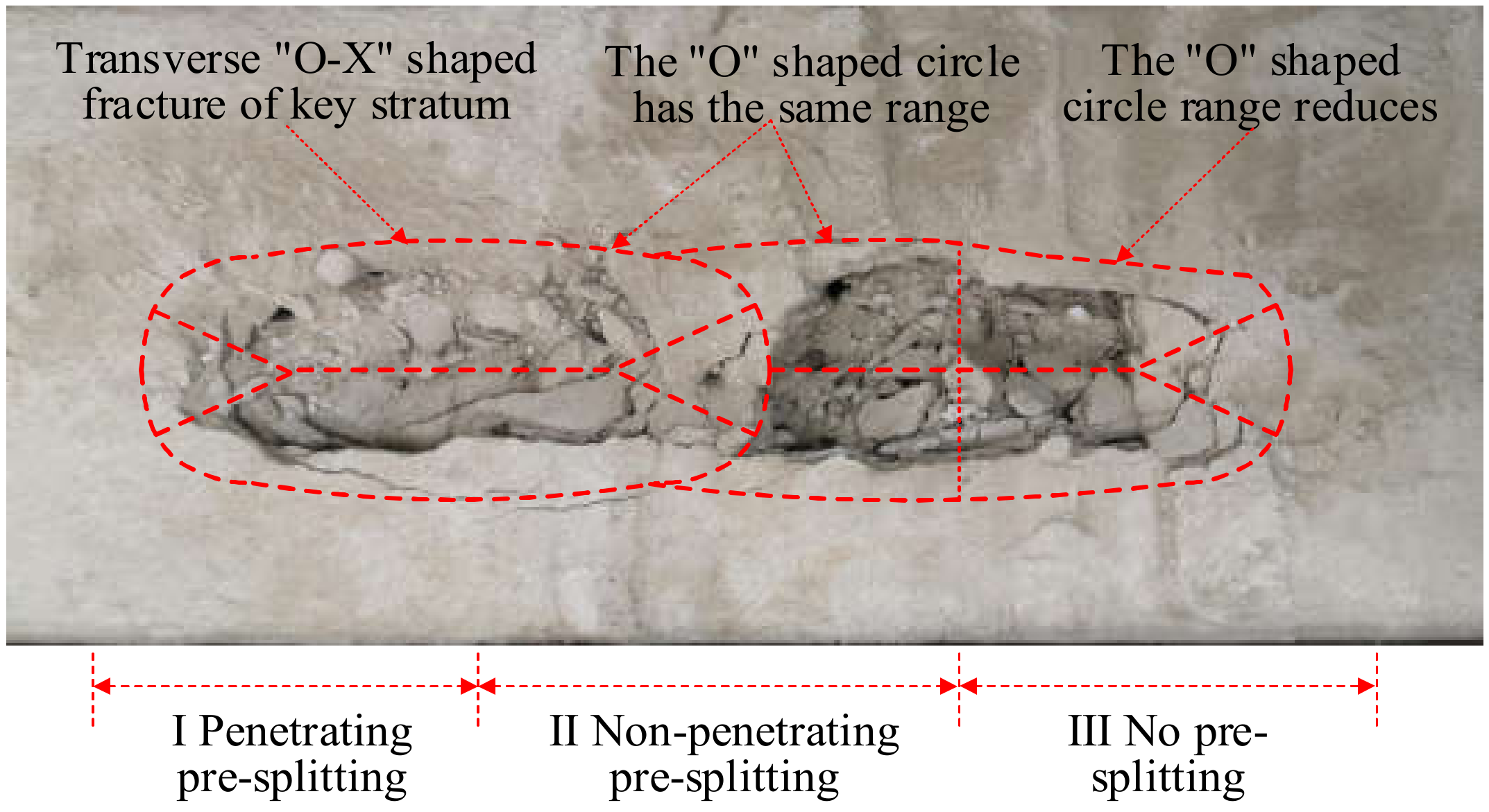
The fracture pattern of the high-key rock layer exhibited a “horizontal O-X shape”, attributed to the periodic collapse distance of the high-key rock layer exceeding the length of the mining panel. As the mining panel advanced, the high-key rock layer underwent periodic collapse, forming a “horizontal O-X shape” fracture structure.
(5)
Prefabricated fractures in the roof modified the distribution of the “O-ring” caving range within the high-key rock layer, leading to its expansion. However, in both the penetrating and non-penetrating pre-splitting areas, the “O-ring” range remained fundamentally consistent. Conversely, when the roof had no splitting, there was a reduction in cleavage intensity, resulting in a narrower O-type cleavage range.
Upon analysis, it was evident that the spatial structure of the fracture in the low- and high-key strata exhibited a “vertical O-X shape” and “horizontal O-X shape”, respectively, as the working face was mined. The presence of pre-splitting in the roof modified both the shape and the location of the fracture in the lower bond strata of the triangular plate. In the absence of roof pre-splitting, a balanced “long cantilever beam” structure was formed; however, roof pre-splitting gave way to a balanced structure characterized by both a “short cantilever beam” and a “masonry beam”. Furthermore, it was observed that roof pre-splitting expanded the O-type caving range within the high stratum while maintaining consistency in its range across the penetrating splitting and non-penetrating pre-splitting areas.

3.2. Variations in the Apparent Resistivity of Overlying Rock

In the process of mining the working face, the rock strata of the physical model are broken and caved. The apparent resistivity of the model varies due to differences in the fracture development degree, caving space structure, and gob compaction degree in different mining stages. Therefore, the rock collapse state in the physical model can be reflected by the change in apparent resistivity. The high-density resistivity method was used to collect interelectrode current data when physical models were mined in different areas. Subsequently, the apparent resistivity of the mining process was calculated.
The apparent resistivity change rate can reduce the influence of background resistivity on the inversion results. The contour distribution of the apparent resistivity change rate can be used to invert the physical model’s fracture development and rock caving during the mining process and reveal the influence law of roof pre-slitting on the caving of overburden rock. The model’s apparent resistivity before mining is ρs, and its change rate after mining is Δρs/ρs. From this, a distribution cloud map of the apparent resistivity change rate can be drawn. A positive change rate indicates an increase in apparent resistivity, suggesting collapse within the rock strata, spatial cracks in the caving rock strata, and large crack openings. Conversely, a negative change rate signifies a decrease in apparent resistivity, indicating that there is compaction within caving rocks under overburden load and that the fracture is closed.
The interelectrode current data for the D1 and D2 survey lines were collected four times, both prior to mining and after mining in zones I, II, and III. This was carried out to analyze the changes in apparent resistivity during the mining process of the working face and subsequently to invert the rock breaking law in the overlying strata along the advancing direction of the working face. Figure 8 illustrates the distribution of apparent resistivity change rates for sections D1 and D2 for the mining areas I, II, and III in the model. The following can be seen from the figure:
(1)
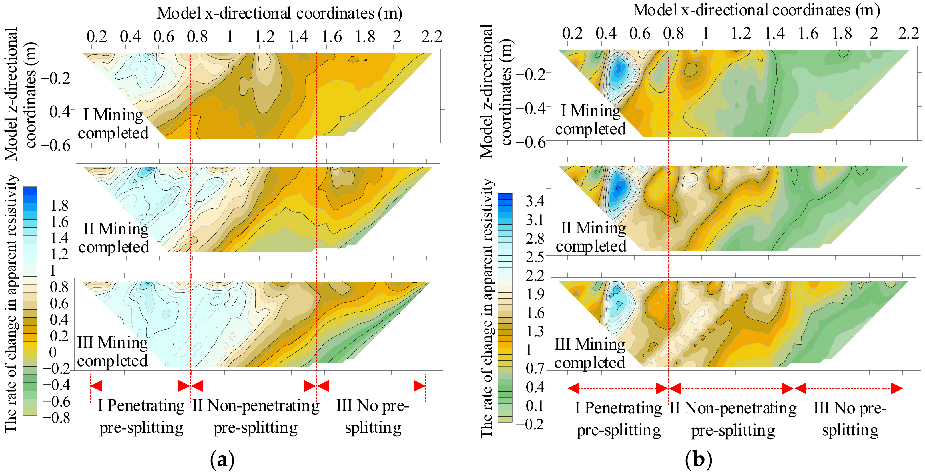
During the mining process of the working face, it was observed that the apparent resistivity change rate of section D2 exceeded that of section D1, indicating a higher degree of overlying strata caving. This could be attributed to the greater distance between D2 and the mining boundary compared to D1, resulting in larger overburden caving and fracture opening and, thus, leading to a higher apparent resistivity change rate.
(2)
The apparent resistivity change rate of section D1 gradually increased with the advancement of mining operations, indicating the progressive development of cracks and an increase in both their number and openness. In the penetrating pre-splitting area, after the completion of mining II and with the continuation of mining III, the fracture number and fracture opening continued to increase. In the non-penetrating pre-splitting area, the fracture development range was small after the completion of mining II. The fracture development continued with the continuation of mining III, which was not much different from that in the penetrating pre-splitting area. In the non-pre-splitting area, there was minimal development of fractures during the mining of the working face. It was evident that cracks gradually developed as the working face was mined in the non-penetrating pre-splitting area, and the apparent resistivity change rate remained consistent with that of the penetrating pre-splitting area, indicating little variation in crack development. The formation of fractures in sections I and II of D1 reduced the cantilever length of the overlying key rock layer, thereby decreasing the load on both the small coal pillars and the adjacent working face gateways and ultimately alleviating pressure on the small coal pillar.
(3)
The apparent resistivity of the entire D2 section showed an increase following the completion of mining activities in the working face. The variation in apparent resistivity within the range of −0.6 to −0.3 m was observed to be smaller compared to that within the range of −0.3 to 0 m, indicating a reduced presence of caving fractures and improved compaction of caving rocks within the −0.6 to −0.3 m range. Conversely, within the range of −0.3~0 m, there were numerous caving cracks and low-density and large spatial cracks in the overburden rock layers. After mining, there was little difference in the apparent resistivity change rate between the penetrating and non-penetrating areas, and the overlying rock in the whole section had the same caving degree. In the area without pre-splitting, the rock layer had not completely collapsed. During the mining of the working face, there was a gradual decrease in the apparent resistivity change rate within the range of −0.3 to 0 m as the cracks gradually closed under the load and the overlying rock gradually collapsed and became dense. After mining, minimal disparity in the apparent resistivity change rate was observed between the penetrating and non-penetrating pre-splitting areas, with uniform overlying rock caving throughout the entire section. Complete collapse of the rock layer did not occur in the areas without pre-splitting. It could be seen that roof pre-splitting led to a higher apparent resistivity change rate and greater overburden caving degree, thereby facilitating rock strata collapse while reducing key rock cantilever length and roof load.
The analysis above revealed significant variation in the apparent resistivity of the overlying rock as a result of roof pre-splitting. There was minimal difference in the apparent resistivity change rate between the penetrating and non-penetrating pre-splitting areas, with similar caving degrees, thereby reducing critical rock overhang and roof load. Non-penetrating pre-splitting in the roof decreased fracture length, facilitating maintenance of the roadway and the end of the mining face area.
Data were collected twice for each of the D3, D4, and D5 survey lines: the initial data were gathered prior to mining operations, while subsequent data were obtained following the completion of mining activities in areas I, II, and III. Subsequently, an analysis was conducted on the changes in apparent resistivity and the degree of overhanging rock caving after mining in areas I, II, and III. Figure 9 illustrates the distribution of the apparent resistivity change rate in sections D3, D4, and D5, subsequent to the completion of mining activities in areas I, II, and III. This figure suggests that after the mining of the working face, there was an increase in the apparent resistivity change rate within the region impacted by roof pre-splitting, indicating a potential upward expansion of prefabricated cracks leading to the collapse of overlying rock and a reduction in the cantilever beam length of high rock layers. Furthermore, the apparent resistivity change rate within the upper strata exhibiting both penetrating pre-splitting and non-penetrating pre-splitting cracks was found to be largely consistent, indicating uniformity in the overlying rock caving degree with minimal variation in the cantilever beam length. Both roof pre-splitting methods could effectively reduce the load on the small-coal-pillar roadway in the adjacent working face. However, there was an increase in the apparent resistivity change rate of the lower layer when there was no pre-splitting in the roof leading to collapse. Conversely, the apparent resistivity change rate of the upper rock layer remained relatively stable, resulting in a large area of the rock layer that had not collapsed. This resulted in a long cantilever structure in the upper rock layer, subsequently increasing the load on the adjacent working face gateway and causing significant deformation of the roadway.
In summary, after pre-splitting in the working face gateway roof, there was an observed increase in the apparent resistivity change rate within the fractured area, resulting in a significant degree of overlying rock caving and a reduction in the length of the roof cantilever beam. As a consequence, this reduced pressure and deformation on the adjacent small-coal-pillar roadway.

3.3. The Waveform Characteristics of Electromagnetic Wave Propagation

The geological radar converts high-frequency electromagnetic waves into short, broad-band pulses to detect objects with electrical differences. After mining activities, the caving of overlying rock alters the dielectric properties of the rock strata. Consequently, the evolution of fractures in the overburden rock can be examined by analyzing changes in waveforms, thereby revealing the impact of fractures on the migration and fragmentation behavior in this area.
The electromagnetic wave propagation on measuring surface L1 in the model was monitored both before and after mining activities in order to evaluate the impact on signal transmission. Figure 10 illustrates the grayscale and waveform of the electromagnetic wave propagation on measuring surface L1. It is evident from the figure that in the absence of mining activity, the electromagnetic wave propagated to generate a low-amplitude reflected wave group, with no displacement along the in-phase axis. The energy groups exhibited a relatively uniform distribution, with pronounced reflection fringes in localized areas. Simultaneously, the electromagnetic waveform was consistent and lacked discernible reflecting surfaces and chaotic reflections. The data indicated a uniform distribution of the model rock strata, consistent dielectric properties, and an absence of discernible crack distribution. After the completion of mining activities, the electromagnetic waveforms in regions I and II became disjointed, leading to chaotic waveforms and causing scattering and diffraction phenomena. Consequently, this resulted in an uneven distribution of energy clusters. In region III, the electromagnetic waveform became disordered and broke along the phase axis within the range of 0.4~0.6 m, while it remained uniform within the range of 0~0.4 m.
It showed that when there was no pre-splitting in the roof, overburden cracks only developed in the range of 0.4~0.6 m. However, under the influence of pre-cracks in the roof, the caving range of the rock strata increased and cracks developed, which changed the propagation path of the electromagnetic wave, resulting in scattering and diffraction. The degree of electromagnetic wave propagation was similar in the penetrating and non-penetrating pre-splitting areas, with minimal disparity observed in overlying rock caving and fracture development.
After the completion of mining operations in the model region I, electromagnetic wave propagation on measuring surface L1 was monitored. Similarly, following the completion of mining activities, electromagnetic wave propagation on measuring surfaces L3 and L4 in model regions II and III was monitored. Figure 11 illustrates the grayscale and waveform of electromagnetic wave propagation on the L2, L3, and L4 measuring planes. It is evident from the figure that there was a significant increase in the amplitude of electromagnetic waves, non-uniform distribution of energy groups, and chaotic waveform patterns within the pre-splitting influence zone. This shows that fractures developed in this area due to the influence of roof pre-splitting, and the rock strata collapsed to form a short cantilever. When no pre-splitting was applied to the roof, there was an even distribution of electromagnetic waveforms with no phase axis dislocation within the model’s z- and y-direction ranges of 0.2–0.3 m and 0.3–0.55 m, respectively. This indicated relatively complete rock layers and the formation of a long cantilever structure. The long cantilever increased the overlying rock load, subsequently elevating pressure in the adjacent small-coal-pillar roadway.
Upon analysis, it was evident that within the pre-splitting influence zone, there was an increase in the amplitude of electromagnetic waves and a non-uniform distribution of energy groups, leading to the collapse of rock strata and formation of a short cantilever. Conversely, in the absence of pre-splitting in the roof, electromagnetic waves were evenly distributed throughout the high rock layer without the occurrence of in-phase axis dislocation, resulting in relatively intact rock layers and the formation of a long cantilever structure. A comparison with the results from high-density electrical methods revealed similar findings in detecting overburden caving. Through roof pre-splitting, both the length and load of the cantilever beam were reduced to alleviate pressure and deformation on the adjacent small-coal-pillar roadway.

3.4. The Displacement Law of Overlying Strata during Mining

During mining of the working face, pre-cracks in the gateway roof have a significant impact on the displacement of the overlying strata. Consequently, internal displacement monitoring points were strategically placed in three distinct areas—penetrating pre-splitting, non-penetrating pre-splitting, and no pre-splitting—to accurately measure subsidence at various levels within the rock strata and elucidate the influence of roof cracks on overburden subsidence. Figure 12 illustrates the impact curve of roof cracks on overburden subsidence. The following can be seen from the figure:
(1)
As the working face was mined, the subsidence at each measuring point exhibited a step-type change in variation trend. Upon mining past a measuring point, there was a sudden sinking of the point. Subsequently, as mining continued in the model, the measuring point experienced sudden sinking several times, and the increase in subsidence gradually decreased and eventually stabilized. The final subsidence at the measuring point diminished with an increase in rock stratum due to uncoordinated deformation caused by caving and dilatation of overlying rock filling the goaf. It was observed that higher rock strata result in smaller subsidence.
(2)
The internal displacement measuring points in the first layer sank as the working face advanced to their location. Upon reaching a position 40 cm from the measuring point, there was no change in subsidence, and ultimately all three measuring points showed consistent subsidence. This indicated that roof pre-splitting had minimal impact on the subsidence of the first layer. The distance between the measurement point of the first layer and the coal seam roof was 94.1 mm, corresponding to a distance of 7.5 m from the site to the coal seam roof. Therefore, within a range of 7.5 m from the coal seam roof, roof pre-splitting had little influence on rock layer subsidence, allowing for free collapse of the rock layers.
(3)
At the internal displacement measuring points of the second layer, a sinking phenomenon was observed after the working face advanced 10 cm at the measured point, and this subsidence remained consistent even after advancing to 60 cm. In contrast, at the displacement measuring point of the third layer, subsidence occurred following a 30 cm advancement of the working face. It is noteworthy that minimal subsidence was observed at this measuring point when there was no roof pre-splitting present. Due to the influence of roof cracks, there was an increase in strata subsidence in the second and third layers, with little variation in measured point subsidence between penetrating pre-splitting and non-penetrating pre-splitting areas. As a result, within the range of 21.3~32.6 m from the coal seam roof, fractures led to an increase in overlying rock subsidence and a reduction in the distance between subsidence stability and the working face. This indicated that roof pre-splitting contributed to enhancing the subsidence of overlying rock and reduced the duration of stability in overlying rock subsidence.
Based on the aforementioned analysis, it was evident that the subsidence of the measuring point exhibited a step-type change trend as the working face advanced. The roof pre-splitting amplified the subsidence of the upper strata and reduced the distance between their stability and the working face. In cases where there was non-penetrating pre-splitting, mining-induced cracks in the working face intersected with each other, leading to rock layer sinking. The disparity in rock strata subsidence between penetrating pre-splitting and non-penetrating pre-splitting in the roof was minimal.

3.5. Stress Distribution in the Surrounding Rock

During the retreat of the working face, roof pre-splitting significantly impacted the advanced stress distribution. During the mining process, the stress variation at each monitoring point in the mining panel gateway roof was analyzed to reveal how roof pre-splitting influences the advanced stress distribution of the roadway. Figure 13 illustrates the characteristics of advanced stress distribution in the gateway during mining panel retreat. This figure illustrates that the average advanced stress at each monitoring point within no pre-splitting area III was 13.23 kPa. The average advanced stress at each monitoring point in penetrating and non-penetrating pre-splitting areas I and II was measured at 18.43 kPa and 15.52 kPa, respectively, representing respective increases of 39.31% and 17.31% compared to the area without pre-splitting. It was evident that roof pre-splitting led to an elevation in the advanced stress within the roadway, with non-penetrating pre-splitting resulting in a lesser degree of increase. This suggested that non-penetrating pre-splitting contributed to maintaining a certain level of continuity within the roof structure, which was beneficial for preserving the front section of the working face. Therefore, it is imperative to enhance temporary support strength within a distance of up to 30 m ahead of the working face and augment the number of single hydraulic props to ensure the maintenance of the pre-splitting roadway.
Movement during mining operations induces an increase in stress within the surrounding rock of the adjacent mining panel gateway. An analysis of stress variation in this surrounding rock was conducted upon the completion of mining at the working face, revealing the influence of roof pre-splitting on stress distribution within the adjacent small-coal-pillar roadway. Figure 14 illustrates the stress comparison curve for each measuring point in the adjacent mining panel gateway after the completion of mining panel retreating operations. This figure demonstrates that in model III, when there was no pre-splitting in the roof, the average stresses at the measuring points of the solid side, the roof, and the small-coal-pillar side of the adjacent mining panel gateway were 13.68 kPa, 9.22 kPa, and 14.22 kPa, respectively. In the roof of the model I penetrating pre-splitting area, the average stress at the measuring points on the solid, roof, and small-coal-pillar sides of the adjacent mining panel gateway were 8.46 kPa, 5.79 kPa, and 8.19 kPa, respectively. These values represent reductions of 38.16%, 37.20%, and 42.41% compared to those observed in the area without pre-splitting. In the roof of the model II non-penetrating pre-splitting area, the average stresses on the solid, roof, and small-coal-pillar sides of the adjacent mining panel gateway were 8.45 kPa, 6.08 kPa, and 8.10 kPa, respectively. These values represent reductions of 38.23%, 34.06%, and 43.04% compared to the area with no pre-splitting, indicating that the stress on the surrounding rock of the adjacent mining panel gateway was decreased after pre-splitting in the mining panel gateway roof. Furthermore, there was minimal difference in stress reduction between the penetrating and non-penetrating pre-splitting conditions. When there was no pre-splitting in the roof, insufficient overlying rock caving occurred after mining, resulting in the formation of a long cantilever structure that caused stress on the surrounding rock of the adjacent mining panel gateway. However, when there was pre-splitting in the roof, the full collapse of the overlying rock after mining reduced stress on the surrounding rock of the adjacent mining panel gateway. In cases where there was non-penetrating pre-splitting, non-penetrating rock masses interacted with each other under dynamic pressure from advance mining, and this had a similar effect to penetrating pre-splitting on relieving stress on the surrounding rock of the adjacent mining panel gateway.
From the above analysis, it is evident that roof pre-splitting led to an increase in advance stress in the mining panel gateway, while a non-penetrating pre-splitting roof exhibited a certain level of continuity with only a minor degree of increase in advanced stress. When there was pre-splitting in the mining panel gateway roof, the stress on the surrounding rock of the adjacent mining panel gateway was reduced after mining, and such stress within the adjacent mining panel gateway remained largely consistent under both penetrating and non-penetrating pre-splitting.

4. Field Application
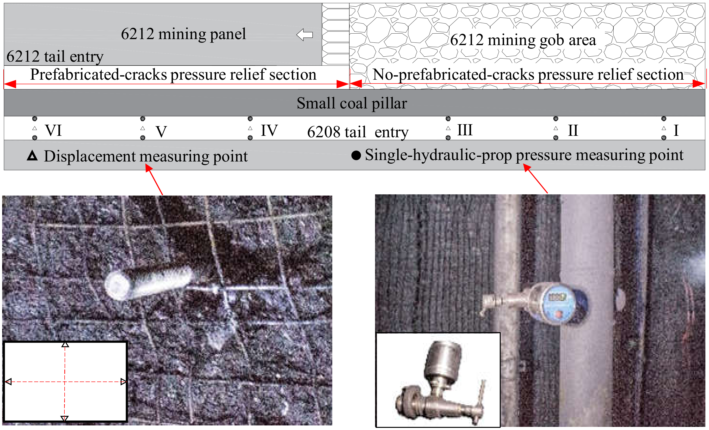
In this study, non-penetrating pre-splitting was employed in the roof of a small-coal-pillar roadway at Wangzhuang Coal Mine in Shanxi Province, China. The 6212 and 6208 mining panels in Wangzhuang Coal Mine were contiguous. As a result of the mining sequence, both panels had been prepared for mining operations, with the 6212 panel being mined first. The width of the small coal pillar between the two working faces was 5 m, and it was subjected to multiple dynamic pressure effects from both roadway excavation and working face mining activities. Pressure relief technology for non-penetrating directional pre-splitting blasting with a deep hole was applied to the tail entry roof of panel 6212, inducing the formation of non-penetrating cracks. The key parameters for non-penetrating cracks in the roof are illustrated in Figure 15. During mining operations at the working face of 6212, the non-penetrating cracks intersected with each other, effectively isolating the tail entry roof of 6208 from that of the working face of 6212. After the completion of mining in the working face of 6212, the overhanging length of the basic roof was reduced, leading to an optimized surrounding rock stress environment for the small coal pillar and the tail entry of 6208, thereby ensuring their protection.
Monitoring stations were established at the tail entry of 6208 to observe the changes in stress and convergence deformation of the adjacent tail entry of 6208 during the mining process of the working face of 6212. Figure 16 illustrates the monitoring scheme for stress and displacement of surrounding rock in the tail entry of 6208. Three measuring stations were positioned at intervals of 25 m within both the no pre-splitting section and the non-penetrating pre-splitting pressure relief section. The specific arrangement and monitoring methods for each station are as follows:
(1)
A hydraulic single column was selected for measurement on the small-coal-pillar and solid-coal-wall sides. The pressure of the single column was measured using an intrinsic safety-type pressure gauge commonly used in mining. The change in the working resistance of the single column was monitored during the mining process of the working face of 6212.
(2)
The displacement measurement points were delineated on the roof and bottom of the roadway, as well as in the middle of the two sides, using a cross-layout method. The convergence deformation of the roadway at these designated points was systematically recorded during the mining process of the working face of 6212.
In the mining process of the working face of 6212, the hydraulic single-column pressure and displacement variation trend in different measuring stations of the tail entry of 6208 exhibited a consistent pattern, with an initial increase followed by stabilization. We selected typical measuring stations for detailed analysis. Figure 17 and Figure 18 illustrate the pressure variation curve of a single column in the tail entry of 6208, as well as the displacement variation curve in the same entry. As shown in Figure 17, the maximum pressures on the solid-coal-wall and small-coal-pillar sides within the no-pre-splitting pressure relief section of the tail entry of 6208 were recorded at 28 MPa and 34 MPa, respectively. In the non-penetrating pre-splitting pressure relief section, the pressure on both sides of the tail entry of 6208 were 20 MPa and 25 MPa, respectively. The pressure in the single column was reduced on both sides of the roadway. As illustrated in Figure 18, the maximum deformation of the roof-to-floor and the two sides of the tail entry of 6208 within the no-pre-splitting pressure relief section were measured at 1228 mm and 1539 mm, respectively. The roadway deformation reached its peak when the working face of 6212 lagged by 65 m. In the non-penetrating pre-splitting pressure relief section, the maximum deformation of the roof-to-floor and the two sides of the tail entry of 6208 were 525 mm and 660 mm, respectively. The roadway deformation reached its peak when the working face of 6212 lagged by 50 m. The overall deformation of the roadway was significantly reduced by 57%, accompanied by a decrease in the distance of the roadway, reaching maximum deformation and a shortened stability time of goaf caving. The analysis suggests that deep-hole, non-penetrating, directional, pre-splitting blasting effectively alleviated pressure and deformation in the roadway.
Figure 19 compares the effects of deformation control on surrounding rock in the tail entry of 6208. The utilization of non-penetrating, directional, pre-splitting blasting to induce non-penetrating cracks effectively managed the stability of the surrounding rock. Field observations demonstrated that this method was successful in controlling the stability of high-stress surrounding rock in roadways with small coal pillars, yielding remarkable results.

5. Conclusions

In this study, the overburden caving characteristics of penetrating pre-splitting, non-penetrating pre-splitting, and no pre-splitting were investigated through three-dimensional physical simulation tests. The apparent resistivity change in the rock layer during mining of the working face was determined, and the propagation law of high-frequency electromagnetic waves in the overlying rock was studied. The stress distribution law of the surrounding rock in non-penetrating pre-splitting small-coal-pillar roadways was examined. Additionally, this study revealed the three-dimensional migration and breaking evolution law of non-penetrating pre-splitting roofs in the advancing direction of the working face. These findings were further validated through field application. This discovery contributes to enriching the theoretical knowledge of non-penetrating pre-splitting pressure relief and has implications for further research on gob-side entry retention and hard roof mining activities under these conditions. The conclusions drawn from this study are summarized as follows:
(1)
When there was no roof pre-splitting, the high layer did not collapse and formed a long cantilever structure. After pre-splitting, there was an increase in the apparent resistivity change rate of overlying rock, and the electromagnetic waveform exhibited scattering and diffraction. In both the penetrating and non-penetrating pre-splitting areas, there was a minimal difference in the apparent resistivity change rate, and the disorder degree of the electromagnetic waveform remained consistent. This indicated that the caving degree and short lateral cantilever length were similar in both pre-splitting areas.
(2)
During the mining process of the working face, there was a discernible step-type change trend for the displacement of the rock strata as the working face advanced. Roof pre-splitting had minimal impact on the displacement of the lower strata, but it led to an increase in the displacement of the upper strata and a reduction in the distance between the collapse stability of the upper strata and the working face.
(3)
Pre-splitting the roof resulted in an increase in the advance stress of the mining panel gateway, while non-penetrating pre-splitting maintained continuity and led to a smaller degree of advance stress increase, thus facilitating the maintenance of the advanced roadway. In cases where non-penetrating pre-splitting was employed for the roof, there was a reduction in stress in the adjacent mining panel gateway after mining, resulting in a pressure relief effect on the surrounding rock stress of the roadway similar to that observed with penetrating pre-splitting.
(4)
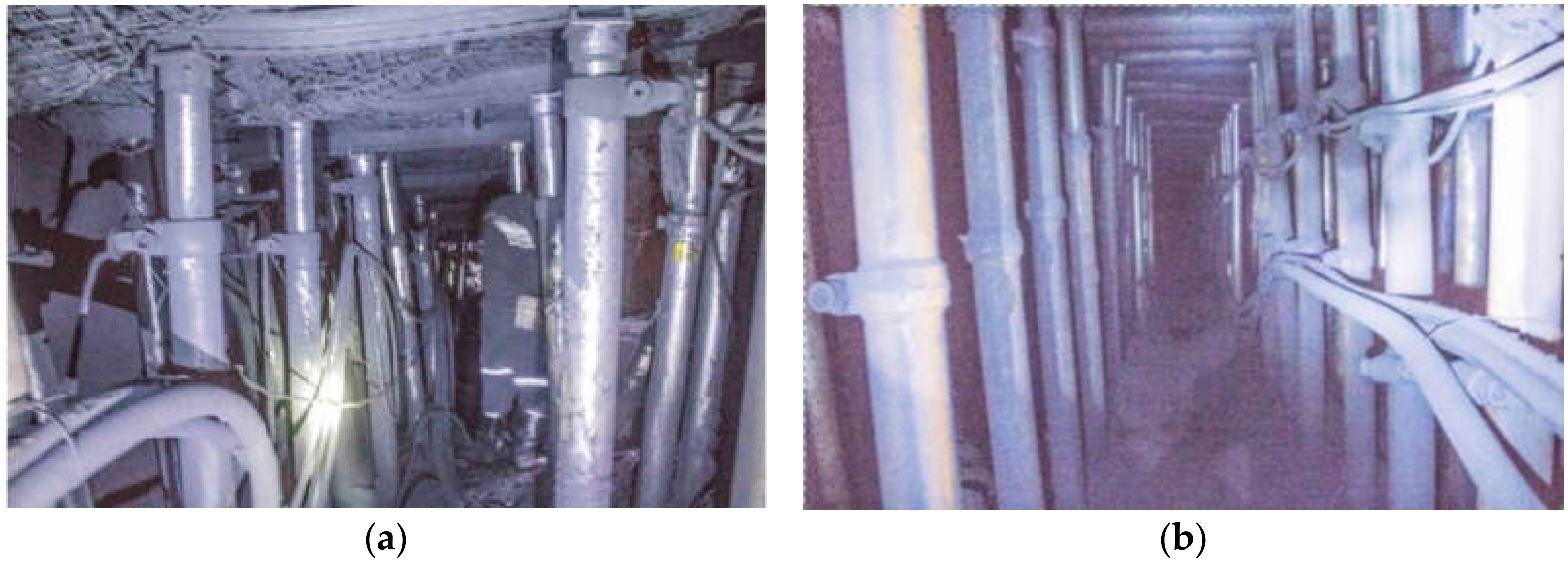
In the non-penetrating pre-splitting pressure relief section, the single-column pressure on both sides and deformation of the tail entry of 6208 after mining exhibited minimal magnitudes. The overall deformation of the roadway was reduced by 57%, and there was a decrease in the distance to reach maximum deformation within the roadway.

Author Contributions

Conceptualization, S.C., Z.M. and X.Z.; methodology, S.C., Z.M. and X.Z.; software, S.C., W.H. and P.L.; validation, S.C., C.Y. and S.L.; formal analysis, S.C.; investigation, S.C. and X.Z.; resources, S.C. and Z.M.; data curation, S.C.; writing—original draft preparation, S.C. and Z.M.; writing—review and editing, S.C., W.H. and P.L.; visualization, S.C.; supervision, S.C.; project administration, S.C.; funding acquisition, S.C., C.Y. and S.L. All authors have read and agreed to the published version of the manuscript.

Funding

This research was funded by Fundamental Research Program Youth Project of Shanxi Province, grant number 202303021212303, 202303021212304, and 202303021212302; Jincheng Key Research and Development Project in the High-Tech Field, grant number 20230101 and 20230102; Scientific Research Foundation for Advanced Talents of Shanxi Institute of Science and Technology, grant number 2023010; College Student Innovation and Entrepreneurship Training Program at Shanxi Institute of Science and Technology, grant number XC2023007 and XC2023008.

Data Availability Statement

The original contributions presented in this study are included in the article; further inquiries can be directed to the corresponding authors.

Acknowledgments

The authors thank the editors and anonymous reviewers for their help in revising and improving the article.

Conflicts of Interest

The authors declare no conflicts of interest.

References

  1. Zhang, Q.; He, M.; Guo, S.; Qi, J.; Yang, J.; Wang, C.; Xia, M.; Li, L. Investigation on the key techniques and application of the new-generation automatically formed roadway without coal pillars by roof cutting. Int. J. Rock. Mech. Min. 2022, 152, 105058. [Google Scholar] [CrossRef]
  2. Barbato, J.; Hebblewhite, B.; Mitra, R.; Mills, K. Prediction of horizontal movement and strain at the surface due to longwall coal mining. Int. J. Rock. Mech. Min. 2016, 84, 105–118. [Google Scholar] [CrossRef]
  3. Chen, J.; Zhou, L.; Xia, B.; Su, X.; Shen, Z. Numerical Investigation of 3D Distribution of Mining-Induced Fractures in Response to Longwall Mining. Nat. Resour. Res. 2021, 30, 889–916. [Google Scholar] [CrossRef]
  4. Guo, S.; Hu, S.; Huang, J.; Gao, Z.; Cheng, Y.; Han, J.; Yang, L. Stability Control Technology for Surrounding Rocks in Gob-Side Entry Driving with Small Coal Pillars under Dynamic Pressure. Energies 2023, 16, 7887. [Google Scholar] [CrossRef]
  5. Peng, C. Research on the breaking mechanism of bolts and cables in the gateway driven along a small coal pillar in the Datong mining area and the corresponding control technology. Front. Earth Sci. 2023, 10, 3389. [Google Scholar] [CrossRef]
  6. Cheng, S.; Ma, Z.; Gong, P.; Li, K.; Li, N.; Wang, T. Controlling the Deformation of a Small Coal Pillar Retaining Roadway by Non-Penetrating Directional Pre-Splitting Blasting with a Deep Hole: A Case Study in Wangzhuang Coal Mine. Energies 2020, 13, 3084. [Google Scholar] [CrossRef]
  7. Ju, F.; Wang, D.; Wang, Z. Coal Pillar Stability Investigation for High-Intensity Mining in the Water-Rich Coal Seam: A Case Study. Min. Metall. Explor. 2024, 41, 743–768. [Google Scholar] [CrossRef]
  8. Liu, Q.; Xue, Y.; Ma, D.; Li, Q. Failure Characteristics of the Water-Resisting Coal Pillar under Stress-Seepage Coupling and Determination of Reasonable Coal Pillar Width. Water 2023, 15, 1002. [Google Scholar] [CrossRef]
  9. Qian, D.; Jiao, H.; Deng, J.; Yang, J.; Jiao, M.; Xian, G.; Yu, C.; Zhu, Y.; Liu, J.; Huang, S.; et al. Instability Mechanism, Pressure Relief, and Long Anchorage Control Countermeasures for Surrounding Rock of Strong Mining Roadway at Large Mining Height Working Face. Minerals 2023, 13, 391. [Google Scholar] [CrossRef]
  10. Bai, J.; Shen, W.; Guo, G.; Wang, X.; Yu, Y. Roof deformation, failure characteristics, and preventive techniques of gob-side entry driving heading adjacent to the advancing working face. Rock. Mech. Rock. Eng. 2015, 48, 2447–2458. [Google Scholar] [CrossRef]
  11. Zhao, Y.; Xiang, Z. Structural Stability and Surrounding Rock Integrity Analysis for Goaf-Side Entry with Small Coal Pillars in Longwall Mining. Appl. Sci. 2023, 13, 6877. [Google Scholar] [CrossRef]
  12. Jiang, Z.; Guo, W.; Xie, S. Coal Pillar Size Determination and Surrounding Rock Control for Gob-Side Entry Driving in Deep Soft Coal Seams. Processes 2023, 11, 2331. [Google Scholar] [CrossRef]
  13. Wang, B.; Zhou, D.; Zhang, J. Research on deformation characteristics and control technology of surrounding rock for gob-side entry with small coal pillar in gently inclined coal seam. Energy Sci. Eng. 2024, 12, 1759–1774. [Google Scholar] [CrossRef]
  14. Shan, C.; Cao, S.; Zhang, Z.; Lin, K.; Sun, J. Numerical Investigation on the Yield Pillar Bearing Capacity under the Two-End-Type Cable Reinforcement. Energies 2023, 16, 6418. [Google Scholar] [CrossRef]
  15. Li, L.; Qian, D.; Yang, X.; Jiao, H. Pressure Relief and Bolt Grouting Reinforcement and Width Optimization of Narrow Coal Pillar for Goaf-Side Entry Driving in Deep Thick Coal Seam: A Case Study. Minerals 2022, 12, 1292. [Google Scholar] [CrossRef]
  16. Chen, X.; Zhou, D.; Zhang, S.; Liang, X.; Dong, Y. Analysis and Prevention of Rock Burst Risk of Working Face under the Influence of Continuous Irregular Triangular Coal Pillar Stress Concentration Area. Acs Omega 2024, 9, 12927–12940. [Google Scholar] [CrossRef] [PubMed]
  17. Guo, S.; Zhang, Q.; He, M.; Wang, J.; Liu, J.; Ming, C.; Guo, L.; Fan, L. Numerical investigation on rock fracture induced by a new directional rock-breaking technology. Eng. Fract. Mech. 2022, 268, 108473. [Google Scholar] [CrossRef]
  18. Zhai, W.; He, F.; Li, L.; Song, J.; Xu, X.; Lv, K.; Li, X.; Wang, D.; Zhang, J. Roof cutting mechanism and surrounding rock control of small pillar along-gob roadway driving in super high coal seam. B Eng. Geol. Environ. 2023, 82, 151. [Google Scholar] [CrossRef]
  19. Zhu, C.; He, M.; Karakus, M.; Cui, X.; Tao, Z. Investigating Toppling Failure Mechanism of Anti-dip Layered Slope due to Excavation by Physical Modelling. Rock. Mech. Rock. Eng. 2020, 53, 5029–5050. [Google Scholar] [CrossRef]
  20. Ghabraie, B.; Ren, G.; Smith, J.; Holden, L. Application of 3D laser scanner, optical transducers and digital image processing techniques in physical modelling of mining-related strata movement. Int. J. Rock. Mech. Min. 2015, 80, 219–230. [Google Scholar] [CrossRef]
  21. He, M.; Jia, X.; Gong, W.; Faramarzi, L. Physical modeling of an underground roadway excavation in vertically stratified rock using infrared thermography. Int. J. Rock. Mech. Min. 2010, 47, 1212–1221. [Google Scholar] [CrossRef]
  22. Fu, J.; Sun, H.; Wen, G.; Li, R.; Zhigang, T.; Tao, Z. Three-Dimensional Physical Similarity Simulation of the Deformation and Failure of a Gas Extraction Surface Well in a Mining Area. Adv. Civ. Eng. 2020, 2020, 8834199. [Google Scholar] [CrossRef]
  23. Ye, Q.; Wang, G.; Jia, Z.; Zheng, C.; Wang, W. Similarity simulation of mining-crack-evolution characteristics of overburden strata in deep coal mining with large dip. J. Petrol. Sci. Eng. 2018, 165, 477–487. [Google Scholar] [CrossRef]
  24. Li, Y.; Ren, Y.; Peng, S.S.; Cheng, H.; Wang, N.; Luo, J. Measurement of overburden failure zones in close-multiple coal seams mining. Int. J. Min. Sci. Technol. 2021, 31, 43–50. [Google Scholar] [CrossRef]
  25. Li, N.; Zhao, H.; Yan, M.; Liu, Z.; Chen, P.; Cai, C.; Lan, X.; Huang, B. Temporal and spatial distribution characteristics of hydraulic crack propagation under true triaxial loading using the direct current method. Int. J. Rock. Mech. Min. 2023, 168, 105416. [Google Scholar] [CrossRef]
  26. Li, X.; Zhang, Q.; An, Z.; Chen, X.; Zhang, F. Experimental research on electrical resistivity variation of coal under different loading modes. Arab. J. Geosci. 2020, 13, 1086. [Google Scholar] [CrossRef]
  27. Chen, G.; Li, Q.; Liu, Z.; Chen, L.; Zhang, Y. Detection method of coal-rock interface and low-resistivity anomalous body based on azimuth electromagnetic wave. Appl. Geophys. 2023, 20, 157–166. [Google Scholar] [CrossRef]
  28. Kang, E.; Meng, H.; Zhao, Z.; Zhao, Z. Distribution Characteristics of the Geoelectric Field in Waste Dump Slopes during the Evolution of Instability Sources under Rainfall Conditions. Appl. Sci. 2023, 13, 6459. [Google Scholar] [CrossRef]
  29. Li, N.; Yan, M.; Zhao, H.; Chen, P.; Cai, C.; Wang, E.; Li, Z. Experimental Study on the Response Characteristics of the Apparent Resistivity of Rock True Triaxial Hydraulic Fracturing. Nat. Resour. Res. 2021, 30, 4885–4904. [Google Scholar] [CrossRef]
Figure 1. Schematic diagram of non-penetrating pre-splitting for small-coal-pillar roadway roofs.
Processes 12 01491 g001
Figure 2. The three-dimensional physical test scheme and arrangement of measuring point: (a) plan view of the physical model and (b) front view of the physical model.
Processes 12 01491 g002
Figure 3. The three-dimensional physical test model: (a) using foam sheets to simulate coal seams and (b) the front view of the completed physical model.
Processes 12 01491 g003
Figure 4. The three-dimensional physical model mining process: (a) the bottom suspension bolt was loosened and (b) the foam board was removed from the bottom.
Processes 12 01491 g004
Figure 5. Experimental data acquisition: (a) rock stratum displacement monitoring; (b) pressure box data acquisition; (c) electrical data acquisition; and (d) model geological radar scan.
Processes 12 01491 g005
Figure 6. Schematic representation of the key layer breaking structure.
Processes 12 01491 g006
Figure 7. Caving pattern at the top of the three-dimensional physical model.
Processes 12 01491 g007
Figure 8. Distribution nephogram of apparent resistivity change rate in D1 and D2 cross section: (a) D1 cross section and (b) D2 cross section.
Processes 12 01491 g008
Figure 9. Nephogram of apparent resistivity change rate distribution of survey lines D3, D4, and D5.
Processes 12 01491 g009
Figure 10. The grayscale and waveform of the electromagnetic wave propagation on the measuring surface L1: (a) grayscale image and (b) waveform image.
Processes 12 01491 g010
Figure 11. The grayscale and waveform of the electromagnetic wave propagation on measuring surfaces L2, L3, and L4: (a) grayscale image and (b) waveform image.
Processes 12 01491 g011
Figure 12. The subsidence of the internal displacement measuring points in the various layers when roof pre-splitting: (a) the first layer; (b) the second layer; and (c) the third layer.
Processes 12 01491 g012aProcesses 12 01491 g012b
Figure 13. Characteristics of advanced stress distribution in gateway during mining panel retreat.
Processes 12 01491 g013
Figure 14. The stress in the surrounding rock of the adjacent mining panel gateway after the retreat of the mining panel.
Processes 12 01491 g014
Figure 15. The critical parameters for non-penetrating pre-splitting of tail entry roof of 6212.
Processes 12 01491 g015
Figure 16. The stress and displacement monitoring scheme for the surrounding rock of the tail entry of 6208.
Processes 12 01491 g016
Figure 17. Pressure variation curve of single column in the tail entry of 6208.
Processes 12 01491 g017
Figure 18. The displacement variation curve in the tail entry of 6208.
Processes 12 01491 g018
Figure 19. The on-site surrounding rock deformation control effect: (a) Deformation is significant in the tail entry of 6208 in the no-pre-splitting section. (b) Deformation is minimal in the tail entry of 6208 in the non-penetrating pre-splitting section.
Processes 12 01491 g019
Table 1. Simulated delamination and strength ratio of similar materials.
Lithology NamePrototype/mModel (cm)Layer NumberCompressive Strength (MPa)Proportion
Layer ThicknessGross ThicknessLayer ThicknessGross ThicknessPrototypeModelSand/Lime/Gypsum
Medium sandstone0.4548.000.5660.00158.620.44546
Sandy mudstone8.0047.5510.0059.44337.500.28646
Mudstone5.3039.556.6349.44232.400.24655
Sandy mudstone6.0034.257.5042.81237.500.28646
Mudstone3.2528.254.0635.31132.400.24655
Fine sandstone2.6025.003.2531.25161.040.46537
Mudstone2.8022.403.5028.00132.400.24655
Fine sandstone10.3519.6012.9424.50498.310.82528
Sandy mudstone2.359.252.9411.56137.010.28646
Coal6.906.908.638.6319.180.08773
Disclaimer/Publisher’s Note: The statements, opinions and data contained in all publications are solely those of the individual author(s) and contributor(s) and not of MDPI and/or the editor(s). MDPI and/or the editor(s) disclaim responsibility for any injury to people or property resulting from any ideas, methods, instructions or products referred to in the content.

