Review

A Comprehensive Review on Enhancing Seasonal Energy Storage Systems through Energy Efficiency Perspectives

Mechanical Engineering Department, Faculty of Automotive, Mechatronics and Mechanics, Technical University of Cluj-Napoca, 400114 Cluj-Napoca, Romania
*
Authors to whom correspondence should be addressed.
Processes 2024, 12(8), 1623; https://doi.org/10.3390/pr12081623
Submission received: 2 July 2024 / Revised: 29 July 2024 / Accepted: 31 July 2024 / Published: 2 August 2024
(This article belongs to the Special Issue Energy Storage Systems and Thermal Management)

Abstract

:
The global energy transition requires efficient seasonal energy storage systems (SESSs) to manage fluctuations in renewable energy supply and demand. This review focuses on advancements in SESSs, particularly their integration into solar district heating systems, highlighting their role in reducing greenhouse gas emissions and enhancing energy efficiency. Tanks are the most suitable solutions for seasonal storage, as they can be implemented regardless of location for volumes up to 100,000 m3. However, pits are the most optimal solutions in terms of cost and size, as they can be constructed for volumes up to 200,000 m3. This review analyses key performance indicators such as energy efficiency, cost-effectiveness, and environmental impact, drawing on case studies from countries like Denmark and Germany. Notable findings include Denmark’s Silkeborg system, which supplies 22,000 households and reduces CO2 emissions by 15,000 tons annually. Challenges such as high initial costs and system maintenance remain, but coupling SESSs with heat pumps enhances thermal stratification within SESSs. This approach can reduce the annual cost by up to 9% and the purchase cost of energy by 23%. Future research should focus on innovative materials, system design optimization, and supportive policies to enhance adoption. In conclusion, advancing SESS technologies and integrating them into renewable energy systems is necessary for achieving sustainable energy solutions and mitigating climate change impacts.

1. Introduction

Fossil fuels currently represent the primary source of carbon emissions and contribute to global warming. The consequences of global warming include rising sea levels, extreme climate changes, glacier melting, food shortages, and destabilization of states’ energy security [1,2]. In the global context of increasing energy demand and concerns about climate change, it is necessary to reduce fossil fuels and speed up the transition to renewable sources of energy [3].
The European Green Deal (EGD) comprises a series of political initiatives at the European Union (EU) level aimed at a green transition, with the goal of achieving climate neutrality by 2050. The proposals included in the ‘Fit for 55’ package, part of the EGD, regulate actions to be taken to reduce the EU’s net greenhouse gas emissions by at least 55% by 2030 compared to 1990 levels. Seventy-five percent of greenhouse gas emissions stem from energy production and usage activities [4].
In the EU, buildings account for 40% of total energy consumption, and the development of construction will lead to an increase in energy consumption. In this context, the EU’s main objectives are related to reducing energy consumption and using renewable energy sources in buildings, with the aim of reducing the EU’s energy dependence and greenhouse gas emissions [5].
In 2020, renewable energy sources reached a share of 22.1% in the EU, exceeding the target set for 2020 of achieving a percentage of 20%. In the field of thermal energy, renewable sources are used to the extent of 23.1% in 2020 [6]. The EU has set the objective of increasing the share of energy obtained from renewable sources to at least 40% of energy production by the year 2030 [7].
Both at the global level and at the EU level, there is a trend of decarbonization in district heating. Figure 1 presents the share of energy sources used in the world by district heating (information taken from [8]).
In 2018, two-thirds of the total heat supplied in centralized heating systems in the EU was obtained from fossil fuels. Figure 2 illustrates the proportion of energy sources used in the EU by centralized heating systems for the year 2018 [9].
Globally, in 2021, nearly 90% of the thermal energy produced in centralized heating systems is generated from fossil fuels (coal—over 45%; natural gas—approximately 40%; oil—3.5%), while the share of thermal energy obtained from renewable sources is below 8% [10].
According to the EU directive on energy efficiency [11], an efficient district heating system uses energy in one of the following proportions: 50% renewable sources, 50% waste heat, 75% cogeneration systems, or 50% a combination of such.
In the presented context, solar district heating systems with seasonal heat storage represent a viable solution for both reducing greenhouse gas emissions and increasing the share of energy produced from renewable sources.
Seasonal heat storage allows sector coupling, with heat storage being up to 100 times cheaper per kWh than electricity storage, depending on the storage method, location availability, and land costs [12].
Large-scale heat storage is based on a time frame of one year, with heat available in summer being stored for use in the winter period [13]. A complete storage cycle is composed of three stages: charging, storing, and discharging [14]. Given that seasonal heat storage is based on sensible heat, the reduction in energy losses for large storage volumes and long storage periods is achieved through solutions placed in the ground, where the soil temperature variation is lower than the outside temperature variation. Heat losses are also influenced by the operating conditions of the storage system: working temperatures, the quality of thermal stratification, and the return temperature of the thermal network [15].
In the last 50 years, since the first implemented systems, seasonal heat storage has focused on four methods: tanks, pits, aquifers, and boreholes [16]. Although aquifers and boreholes are cost-effective options compared to tanks and pits, low-temperature regimes and hydrogeological conditions limit their use. In the case of tanks and pits, the temperature difference can reach 30 K, a fact that allows operation with high charging/discharging thermal powers [17].
The present work introduces novel insights into seasonal energy storage systems (SESSs) by offering a comprehensive review and synthesis of the latest advancements in these technologies, particularly focusing on their integration into solar district heating systems. Unlike previous studies that primarily concentrated on individual storage methods or specific case studies, this work provides a holistic analysis encompassing various storage methods such as tanks, pits, boreholes, and aquifers. It evaluates key performance indicators like energy efficiency, cost-effectiveness, and environmental impact across a selection of case studies from different countries. The main contributions of this paper include a detailed comparative analysis of different seasonal storage methods, highlighting their energy and exergy efficiency, economic feasibility, and environmental benefits. By emphasizing the integration of SESSs with solar district heating systems, the study underscores the significant role of these technologies in reducing greenhouse gas emissions and enhancing energy efficiency. The review also identifies and discusses recent technological innovations, such as improved storage materials, advanced insulation methods, and optimized system designs, addressing a critical gap in the literature by incorporating the latest advancements comprehensively.

2. State of the Art

2.1. Bibliometric Analysis

The selection of bibliographic references required for the study of the chosen issue involves going through a series of steps, which are presented below.
In the initial phase, the keywords and characteristic expressions of the studied field are established. The search is conducted using the following words/expressions: solar district heating with seasonal storage, seasonal thermal energy storage in district heating and cooling, tank seasonal thermal energy storage, seasonal solar thermal energy storage, long-term thermal energy storage, and sensible thermal energy storage.
To obtain results that can be subsequently utilized, it is necessary to consult databases from which the most representative bibliographic resources in the studied field can be extracted. In this regard, databases such as Science Direct, Scopus, Springer Link, Wiley Online Library, Web of Science—Clarivate Analytics, PROQUEST Central, and IEEE were used. At the beginning of the study, the Science Direct database was queried, and a search was conducted using the key phrase “solar district heating with heat seasonal storage”. The analysis was carried out to examine the interest in this research area, including scientific articles and review articles. The evolution of publications in recent years is presented in Figure 3.
As observed, over the past 20 years, scientific papers published in the field of solar district heating with seasonal heat storage have experienced exponential growth. The increasing trend in this field in recent years underscores the importance of studying it.
Figure 4 shows a word-cloud diagram that highlights the keywords from the works cited in this study.
Keywords like “district heating” and “thermal energy storage” are prominent in the cited references, given the specificity of this review article. Among the keywords, it can be seen that “district heating” is linked with “renewable energy”, “trnsys” (simulation software), and “seasonal storage”, reflecting current efforts to integrate renewable energy into centralized heating systems and optimize them for long-term storage.
The “thermal energy storage” keyword is associated with “seasonal thermal energy storage”, “thermal stratification”, and “exergy”, highlighting advanced storage methods and their efficiency. The shift from simpler solutions like “sensible heat storage” and “heat transfer” to more complex approaches shows technological advancements and a move towards sustainable solutions.
The color gradient from blue (1990) to yellow (after 2020) indicates increasing interest over the decades, with recent research focusing on integrating centralized heating systems with seasonal thermal storage and renewable energy, pointing towards future sustainability and efficiency.

2.2. Seasonal Storage Methods Based on Sensible Heat

The period of thermal energy storage ranges from a few hours (daily storage) to several months (seasonal storage). In some climatic zones, heating of homes is necessary in winter, while cooling is required in summer. Through seasonal thermal energy storage systems, it is possible to accumulate heat available during the summer months to meet the heating needs during the winter period [18].
The main methods used for seasonal thermal energy storage are based on sensible heat forms [16]. Storing thermal energy in the form of sensible heat is achieved by varying the temperature of storage materials. The amount of heat stored is proportional to the density, specific heat, volume, and temperature variation in the storage materials [19].
Currently, four main types of seasonal storage facilities are used: tanks, pits, boreholes, and aquifers [20]. The characteristics of seasonal thermal energy storage concepts are presented in Table 1 [16,17,21,22,23,24].
Tanks are structures made of pre-stressed reinforced concrete or stainless steel, with water being the commonly used storage medium. Hot water tanks are often heavily insulated with a thick layer of insulation due to their large heat transfer surfaces [17]. For instance, storage tanks in Friedrichshafen and Hamburg, Germany, have been insulated with mineral fibers with a thickness of 0.3 m, while in Cosenza, Italy, the storage tank was insulated with a layer of 0.2 m expanded glass foam gravel [25]. Minimizing thermal losses is achieved by using thermal insulation up to one meter thick made from materials such as glass wool, polyurethane, extruded polystyrene (XPS), expanded polystyrene (EPS), etc. [21]. These structures are typically installed underground, but they can also be mounted outside a building, above ground [21,24]. In Hamburg, Cosenza, and Hannover, the storage tanks were buried underground, while in Friedrichshafen and Munich, they were partially buried, and in Ilmenau and Rise, they were positioned above ground [25]. The tanks operate on the principle of thermal stratification, so due to the difference in density, the water at the top of the tank is warmer than the water at the bottom [21,24]. In order to maintain thermal stratification throughout the year, it is necessary to automate and control the loading and unloading processes, aiming to minimize exergy losses due to heat transfer and mixing of water flow [26]. The geometric shape of the hot water tanks must be chosen so that the heat losses are as small as possible and, implicitly, the storage efficiency is as high as possible [19]. In the case of buried tanks, it was found that the optimal geometry of the storage tanks is the vertical cylindrical shape [17,27,28], possibly also spherical [29]. The condition of the soil has an influence on the choice of geometry in terms of the maximum available land area and the maximum excavation depth [17].
Pits are excavations made in the ground and covered with sheets of polymeric materials welded on the lateral sides and on the bottom of the basin, with the purpose of achieving the construction’s waterproofing. The storage medium is either water or a mixture of gravel and water [17,20,23]. In constructing the facility, a load-bearing framework such as reinforced concrete is not necessary, as the stones bear the load and transfer it to the lateral walls and the bottom of the basin, thus reducing costs [21]. This technology appears to be the most cost-effective when very large thermal capacities are required. Until now, constructed covered basins have volumes of up to 200,000 m3 [20]. For instance, pits have been constructed in Dronninglund (62,000 m3), Marstal (75,000 m3), Gram (122,000 m3), and Vojens (200,000 m3) [25]. In order to reduce heat loss, the lateral sides, the bottom of the basin, and its upper part, are thermally insulated [21]. The specific heat capacity is lower when using a mixture of gravel and water compared to using water alone as the storage medium. Consequently, the storage volume of the basin needs to be approximately 50% larger than when using a water tank in order to compensate for the difference in energy density of the storage medium [17]. The storage technology using a mixture of gravel and water represents a substantial cost-saving alternative in construction [22].
Drilling is a technology that exploits the thermal capacity of the soil to store and transfer thermal energy to/from the ground (clay, sand, rock, etc.). Thermal energy storage systems through drilling consist of an array of deep vertical drills that are carried out in soil or rock. Generally, drilling is conducted at depths ranging from 30 to 200 m [20,22,23]. The optimal depth of the drills depends on several factors, such as the thermal conductivity of the soil, soil temperature, groundwater level, thermal load profile, and distance to other similar storage systems [17]. Insulation and a waterproof membrane are necessary at the top of the drill site to reduce thermal losses to the surrounding environment [20,23]. Storage systems with drilling have been constructed in Braedstrup (19,000 m3), Neckarsulm (528 drills, 63,000 m3), and Crailsheim (37,500 m3) [20,30].
Aquifers are geological structures that contain groundwater. Aquifers are used as a storage medium, while groundwater acts as a thermal agent [23,24]. From aquifer deposits, groundwater is extracted through a cold well, then heated and pumped back into the aquifer deposit through a hot well. The construction of such systems can only be carried out with the permission of the authorities responsible for groundwater management [20].
Both boreholes and aquifers are used for heating and cooling, presenting the advantage that there are large volumes of storage, but the energy density and thermal conductivity are relatively low [31].
The main advantages and disadvantages of seasonal thermal energy storage systems are highlighted in Figure 5, where red color indicates a higher water temperature, while blue color represents a lower water temperature.
Synthesizing the characteristics of seasonal heat storage technologies, Table 2 presents the most important features of each method.
Among the mentioned seasonal storage methods, hot water tanks are the most commonly used because they represent the most viable solution for implementation in any location.

2.3. Seasonal Heat Storage Tanks

2.3.1. Constructive Parameters

The large volume required for seasonal storage systems makes these systems more suitable for underground placement [21]. The volume of seasonal storage is higher in cities with severe winters [32]. In general, seasonal sensible heat storage systems with a large volume are more efficient than those with smaller volumes at the same energy density [33]. Seasonal storage is energy efficient for systems with a volume of at least 1000 m3 [25].
The A/V ratio has an influence on the height and diameter of the tank. Larger storage volumes have a positive effect on storage efficiency. Theoretically, a spherical storage tank is the most optimal option because it has the lowest A/V ratio [25]. The ratio h/d is the ratio between the height of the tank and its diameter and is a characteristic size for cylindrical tanks [32]. For known systems in Europe, the h/d ratio varies between 0.22 and 3.8. Table 3 presents the geometric characteristics of some seasonal storage tanks in Europe.
Seasonal storage tanks are usually buried in the ground to reduce heat loss. In the case of using seasonal heat storage in solar heating systems, the location of the tank buried in the ground contributes to the increase in the solar fraction. In the case of tanks buried in the ground, the cost for their realization is higher because additional costs arise due to the excavation of the soil [33]. Storage tanks can also be located partially buried in the ground, on the roof, or outside of a building [16,24]. Despite the lower excavation costs for partially buried tanks, an increase in costs arises from the need for additional insulation at the top. Tanks mounted above ground have no hydrogeological limitations because they do not meet underground water [17].
Table 4 shows the location method and the specific geometric shape of some seasonal storage tanks in Europe [25].
The structure of the tank must be chosen so that it can take the stresses to which the tank is subjected. The most used structural materials are concrete, high-density concrete, steel, steel + concrete, stainless steel, and glass fiber reinforced plastic. The performance of storage systems depends not only on the construction elements of the system but also on the surrounding hydrogeological conditions. In the case of buried tanks, the different surrounding materials influence the performance of the systems. The surrounding materials are characterized by density, thermal conductivity, diffusivity, and heat capacity. Coarse gravel is the preferred surrounding material over granite and limestone [25].
The materials of the structural element and their thickness specific to some seasonal storage tanks in Europe [22,25] are presented synthetically in Table 5.
The tank is insulated around it to minimize heat loss. The insulation layer, up to one meter thick, is made up of various insulating materials such as glass wool, polyurethane, XPS, EPS, glass foam, etc. [21]. Increasing the thickness of the tank insulation also increases installation costs while the costs of lost thermal energy are reduced. The most economical insulation thickness occurs when the sum of both types of costs is the lowest [35]. The distribution of insulation around the tank shell can be achieved in several ways. Usually, the bottom of the tank is not insulated; it is only insulated if the structure is mounted at a depth where the water table is encountered [17].
Table 6 presents the material and thickness of insulation specific to some seasonal storage tanks in Europe [22,25].
The constructive parameters identified in the scientific articles are summarized in Table 7.
When analyzing the literature, it was found that the dimensioning issue most addressed is related to the storage volume and insulation. It is an opportunity to study the aspects related to the geometric shape and structure of the storage tank.

2.3.2. Parameters Related to Efficiency

The overall energy efficiency of the storage process (ηst) is a parameter that describes the performance of the storage system. The overall energy efficiency can be expressed as the ratio of the energy recovered from the storage tank during the discharging process to the energy accumulated in the tank during the charging process [19,55]. Table 8 presents the global energy efficiency values of the seasonal storage tanks identified in the literature.
The discharge energy efficiency (ηdes) is a parameter that characterizes the evaluation of the discharge process of the storage tank, which is the ratio between the energy recovered from the storage tank during the discharge process and the sum of the energy accumulated in the tank during the charging process and the energy lost from the storage tank [19,55]. The charging energy efficiency (ηchr) is a parameter that characterizes the evaluation of the charging process of the storage tank, which is the ratio between the energy recovered from the storage tank during the discharge process together with the energy lost from the storage tank and the energy accumulated in the tank during the charging process [19,55].
Exergetic efficiency (ψst) is a parameter that describes the exergetic performance of the storage system. The exergetic efficiency during the storage period is the ratio between the exergy recovered from the storage tank during the discharge process and the exergy accumulated in the tank during the charging process [19,23,55].
The stratification number (Str) is an efficiency parameter that illustrates thermal stratification. This performance parameter has sometimes been used to assess the negative impact of stratification in storage tanks. Str is characterized by the ratio of the average temperature gradients at any time to the maximum temperature gradient for the discharge/charge process [17,27].
The MIX number is dimensionless and expresses the degree of mixing that occurs during a tank loading process. The MIX number is calculated based on the moment of energy [17,40]. The thermal momentum for a storage tank is an integration along its vertical axis of the contained sensible energy. The importance of this indicator is marked by the possibility of determining the degree of thermal stratification of the tank, with the value 0 representing a perfectly stratified (unmixed) tank and the value 1 indicating a completely mixed tank [17,27,36,40].
The efficiency parameters identified in the scientific articles are summarized in Table 9.
Following the analysis of efficiency parameters, it is evident that studies focusing on exergetic efficiency, as well as stratification and MIX invariants, are particularly relevant.

3. Seasonal Energy Storage through an Efficiency Lens

3.1. The Evolution of District Heating toward Synergy with Seasonal Heat Storage

In the design and operation of central heating systems, the observed trend over time is the continuous reduction in the thermal agent temperature. Currently, globally, fourth-generation central heating systems (CHS-G4) are being implemented, characterized by flow temperatures in the range of (50–60) °C and return temperatures close to 25 °C [61]. The characteristic temperatures and energy efficiency for each generation of district heating are presented in Figure 6.
The thermal agent used in the first generation of district heating systems, introduced at the end of the 19th century, was steam. The distribution system of the thermal agent was made of concrete pipes. Today, this type of system is still used in some areas of New York and Paris [62,63]. Between the 1930s and 1980s, the second generation of district heating systems was implemented. The thermal agent used was hot water (with a temperature above 100 °C). The thermal agent was transported through insulated steel pipes, and consumers were supplied through tubular heat exchangers [62,64]. At the end of the 1970s, third-generation district heating systems began to be used. These systems use hot water at a maximum temperature of around 90 °C, with the thermal agent transported through prefabricated insulated pipes buried in the ground [62].
Figure 7 illustrates the evolutionary process of generations of central heating systems.
In the first three generations of district heating systems, thermal energy production was achieved through the combustion of fossil fuels, and the supplied buildings had a high demand for heat [65]. The depletion of fossil resources and the need to reduce carbon emissions have led to a new type of district heating system that utilizes renewable energy sources, with the consumers of the centralized heating system being buildings with low heat demand. The implementation period of the CHS-G4 technology is planned for 2020–2050 [63,66].
In the context of CHS-G4, solar heating systems can be used as an alternative to providing heat in the traditional urban heating system. Due to the seasonal discrepancy between solar radiation availability and the heat demand for building heating, it is necessary to implement seasonal storage systems to increase the share of solar energy in urban heating systems. Long-term storage of thermal energy can also be useful for coupling other heat sources to the network [63,67]. In addition to renewable energy sources, in the case of CSH-G4, it is possible to use residual heat recovered from industry [68] and waste incineration through combined heat and power (CHP) [69] with significant energy and environmental savings.
Currently, worldwide studies and early-stage implementation are underway for fifth-generation district heating systems (CHS-G5) characterized by thermal agent temperatures close to ambient temperature [70]. In these conditions, the thermal agent cannot be directly used in the heating system, thus necessitating the integration of water-to-water heat pumps between buildings and the thermal network. These heat pumps can bring the thermal agent to the necessary parameters for the indoor heating system and domestic hot water (DHW) preparation. The advantages of CHS-G5 are related to reducing heat losses in the distribution network and optimizing the exploitation of low-temperature energy sources by adapting the temperature required for each consumer. The drawbacks of CHS-G5 systems are marked by more complex substations, which involve higher investments compared to traditional systems, and larger diameter pipes due to the small temperature differences between supply and return pipes, leading to higher volumetric flows for the same thermal power [64,71].
In the current context of the development and implementation of CHS-G4 and CHS-G5, the study of heat storage systems that contribute to integrating as much solar energy as possible into centralized heating systems is relevant.
In Table 10, the most important countries and regions contributing to solar district heating by the end of 2021 are presented, detailing the collector area, number of systems, and installed thermal power.
In Scandinavian countries such as Denmark and Sweden, as well as in Austria, Germany, Spain, and Greece, large-scale solar thermal systems began to be used in the early 1980s. The implementation of such systems has largely occurred in Europe up to 2016. In recent years, new large-scale solar thermal systems have also been developed outside of Europe, particularly in China. By the end of 2021, 530 large-scale solar thermal systems (with a thermal power greater than 350 kW and a minimum area of 500 m2) had been put into operation. Among these, there were 299 solar thermal heating systems, with a total surface area of solar collectors of approximately 2.35 km2 and a total installed thermal power of 1645 MW [72].

3.2. Parameters Related to Performance Metrics

To discuss the performance of the storage system, it is necessary to focus on several important indicators: energy efficiency, cost-effectiveness, and environmental impact. It is difficult to determine which of these is the most advantageous, as a low cost often corresponds with a low environmental impact, necessitating the identification of an optimum balance.
Multi-objective analyses identify the optimal options for implementing seasonal storage systems, considering energy efficiency, cost-effectiveness, and environmental impact. The optimal storage volume can be determined by integrating a solar fraction as large as possible while minimizing heat losses until the excavation costs and materials are justified [73].
Pareto analyses were carried out in several studies. For cities in southern Chile, incorporating seasonal heat storage systems into district heating can enhance system performance, reduce emissions by approximately 90%, and increase the levelized cost of energy (LCOE) by less than 20% compared to a conventional network [74].
In the case of a solar district heating system with seasonal heat storage in Barcelona, with an annual heat requirement of 4225 MWh, the solution that pursues the minimum cost reduces the total cost by 16%, while the impact on the environment is reduced by 82% compared to a conventional system. In the case of the solution that pursues the minimum environmental impact, the total cost is reduced by 12%, and the environmental impact is reduced by 85% compared to a conventional system. For the minimum cost solution, 4600 m2 of solar collectors and a volume of 38700 m3 are required, while for the minimum environmental impact solution, 7000 m2 of solar collectors and a volume of 32100 m3 are required [75].

4. Case Studies

The selection of case studies for this study is based on the identification of exemplary implementations of SESSs integrated with solar district heating. The chosen case studies represent a diverse range of geographic locations, climatic conditions, and technological approaches, providing a comprehensive overview of the current state and potential of these systems. By examining these specific instances, the review aims to highlight best practices, identify challenges, and propose solutions for enhancing the efficiency and scalability of seasonal energy storage in various contexts.
The methodologies used in the case studies addressed are summarized in Table 11.

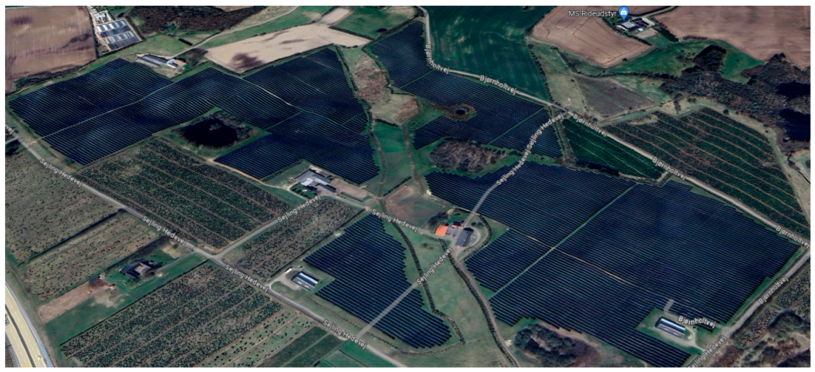
4.1. Case Silkeborg, Denmark

The largest solar district heating system in the world is installed in Silkeborg, Denmark. The system supplies 22,000 households, covering 20% of the energy demand (representing the solar fraction), which is provided by solar energy. The installation consists of 12,436 solar collectors, with a total area of 156,694 m2. The solar collectors produce both thermal energy and electricity and are constructed from recyclable materials such as aluminum, copper, glass, mineral wool, and rubber. In heating the thermal agent, the efficiency of the collectors is 3–4 times higher than in electricity production. The seasonal storage system consists of 4 steel, unpressurized tanks, each with a capacity of 16,000 m3 [76].
Figure 8 illustrates the solar district heating system in Silkeborg, Denmark.
The CO2 emissions have been reduced this year by 15,000 tons, with the municipality of Silkeborg already reaching its emission reduction targets by 45% since 2020 [76].
The economic benefits of the system for the first 20 years of operation are estimated at approximately 17 million euros. These advantages arise from the reduction in operating costs, capital expenses, fuel costs, environmental costs, CO2 emission taxes, tax distortion, and return from the sale of electricity [76]. In the first 20 years of operation, forecasts show that natural gas savings in the amount of 2280 TJ of energy will be achieved [76].

4.2. Case Vojens, Denmark

One of the largest solar systems in the world has been operational since 2016 in Vojens, Denmark. The system consists of a solar field spanning 70,000 m2 and a covered basin for heat storage, with a volume of 200,000 m3. The seasonal heat storage system enables the solar collectors to supply more than half of the annual heat demand [77].
A representative illustration of the system is presented in Figure 9.
Even though Vojens is located in an area with low solar potential, the solar thermal system, along with the seasonal heat storage system, contributes 50% of the annual heat demand. The reduction in CO2 emissions reaches approximately 6000 tons per year [78].
The investment costs for storage amounted to 16 million euros, and the price of thermal energy for this system is 40 EUR/MWh, below the average price of heat for a natural gas system in Denmark, which is 60 EUR/MWh [79].

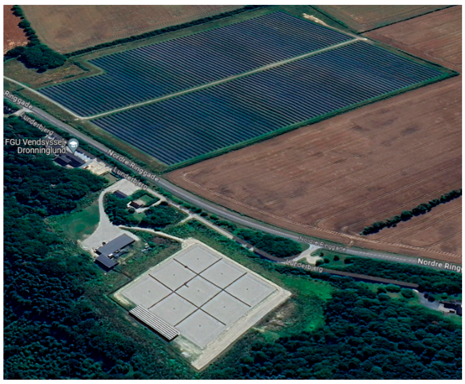
4.3. Case Dronninglund Fjernvarme, Denmark

The system at Dronninglund Fjernvarme, Denmark, consists of 2982 solar collectors with a total area of 37,573 m2 and a seasonal hot water storage tank with a volume of 60,000 m3. The system provides a solar fraction of approximately 50%. The solar collectors are tilted at 35° to maximize annual solar efficiency [80].
Figure 10 illustrates the solar collectors and the seasonal storage tank for the solar heating system in Dronninglund.
During the summer, surplus solar energy is utilized to charge the storage system up to a maximum temperature of 90 °C. Hot water from the tank is discharged from the upper part, while cold water returns to the lower part of the tank at a temperature of around 40 °C. If the temperature in the upper part of the storage system drops below the supply temperature of the district heating network, the required energy can be supplied by an absorption heat pump and a biofuel-fired boiler [81].
The system’s specific cost was 389 EUR/m2 of collector aperture area, with 20% (EUR 2.8 million) of the total funded by the Energy Technology Development and Demonstration Program, supported by the Danish Energy Agency. The system’s integration of multiple energy sources and high solar fraction, enabled by seasonal heat storage, results in a heat price of 50 EUR/MWh, slightly higher than other solar district heating systems in Denmark [74].

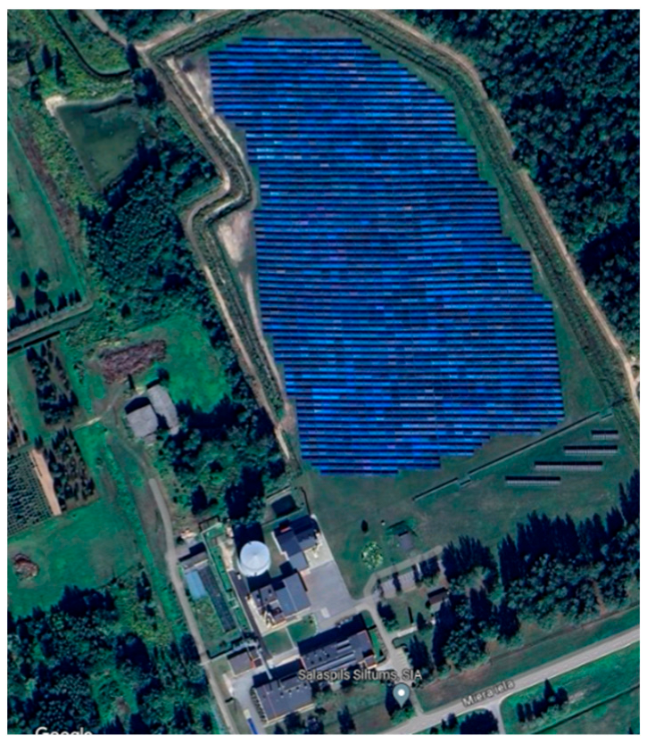
4.4. Case Salaspils, Letonia

The solar heating system in Salaspils, Latvia, is served by a solar field covering 21,672 m2 and a biomass boiler with a thermal capacity of 3 MW. Thermal energy is stored in a hot water tank with a capacity of 8000 m3. This system based on renewable energy provides 90% of the district heating network’s thermal energy demand [82]. Figure 11 presents the centralized solar heating system in Salaspils, Latvia.
The solar thermal field with the storage tank configuration achieves the production of thermal energy, accounting for 20% of the annual heat requirement. After the system was put into operation in this configuration, the energy performance indicator reached 95%, leading to a 12.7% reduction in heating tariffs compared to 2016, while the emission factor decreased by more than half [83].
The solar district heating system in Salaspils significantly reduces greenhouse gases, including CO2, NOX, and other harmful emissions. Its implementation has cut emissions by about 20%, and CO2 emissions have decreased by approximately 90% over the past decade [76].

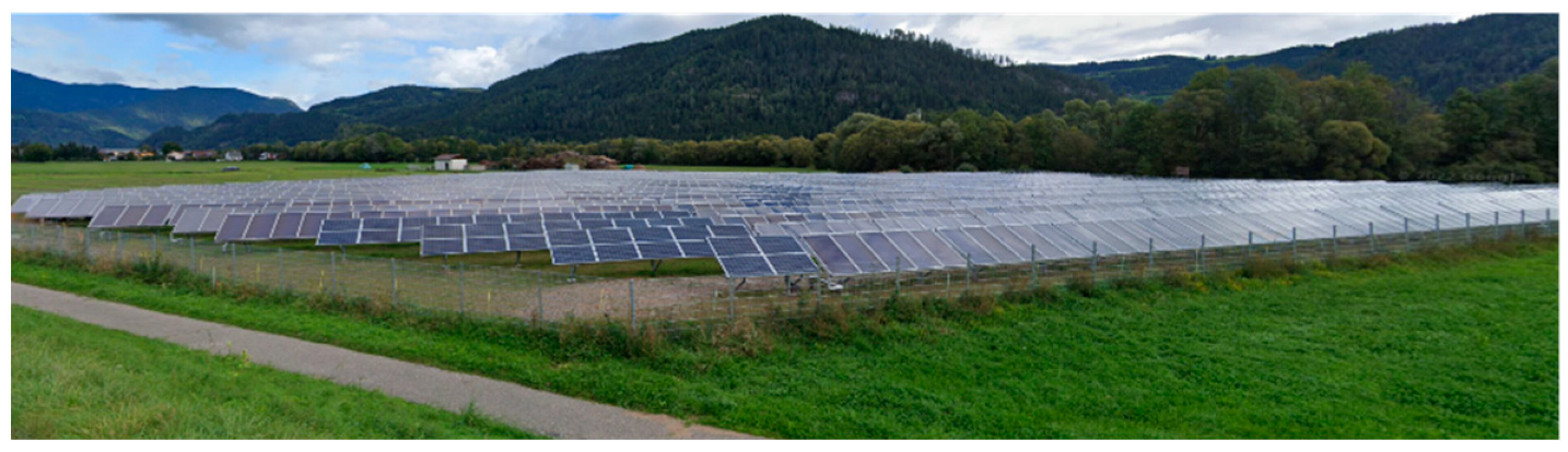
4.5. Case Friesach, Austria

The largest solar heating system in Austria is located in Friesach. The system consists of 436 solar collectors with a total area of 5750 m2 and annually produces 2.5 GWh, providing a solar fraction of 15%. Thermal energy is stored in a 1000 m3 tank at a temperature of 90 °C [84].
Figure 12 presents the solar heating system in Friesach, Austria.
The costs of the solar field and storage tank totaled approximately EUR 2 million, with a specific cost of 348 EUR/m2 [84].

4.6. Zhangjiakou, China

The Institute of Electrical Engineering, Chinese Academy of Sciences, conducted a study on a large-capacity seasonal thermal energy storage (STES) project located in Zhangjiakou [85,86]. The project features a thermal storage volume of 3000 m3 and solar heliostats with a collecting area of 650 m2 to gather solar thermal energy. This energy is stored in a water tank, with temperature changes monitored during storage and release processes. The research focused on solar energy collection efficiency, thermal storage efficiency, and methods to minimize heat loss. The system efficiently manages the energy demand for cooling in summer and heating in winter, demonstrating increased efficiency and reduced CO2 emissions. This project highlights the potential of seasonal storage to optimize energy resources in regions with varied energy demands throughout the year.

4.7. Drake Landing Solar Community, Canada

The Drake Landing Solar Community in Alberta, Canada, uses a centralized solar heating system with seasonal thermal energy storage [87]. The project employs 144 boreholes for long-term heat storage, providing up to 90% of the community’s annual heating needs. This case study illustrates the extremely high efficiency of seasonal storage and its positive impact on reducing CO2 emissions, demonstrating the viability of this technology in Canada’s cold climate.
The analysis in [87] reveals that a house in Drake Landing has a lower environmental impact compared to other Canadian homes. A conventional Canadian home produces 6.34 tons of CO2 annually, while a home connected to the Drake Landing solar heating system produces only 1.91 tons, reducing emissions by 4.43 tons of CO2.

4.8. Langkazi, Tibet

The installation in Langkazi, Tibet, consists of 22,275 m2 of solar collectors and a hot water pit for heat storage with a capacity of 15,000 m3 [81]. Through a thermal network with temperatures of 65 °C on the flow and 35 °C on the return, the heating system supplies 100,000 m2 of living space. For periods with a low intensity of solar radiation, two electric boilers with a total installed power of 3 MW ensure the heat requirement. The solar fraction exceeds values of over 90%, with the heat only being used for the purpose of heating homes in the winter period [88].
The level of development and implementation of district heating systems with seasonal heat storage, as well as the global trend towards energy concerns and environmental protection, fully justify the study of seasonal heat storage systems.

5. Challenges, Barriers and Opportunities

5.1. Challenges of Implementing Solar Heating Systems with Seasonal Heat Storage

One significant challenge in developing storage systems is the cost of implementation. Currently, the specific costs are still too high for many applications, necessitating significant efforts to make these investments feasible [22]. As shown in [89], the specific costs for seasonal thermal storage decrease as the storage volume increases. Storage volumes under 1000 m3 have the highest specific costs, exceeding 350 EUR/m3. Volumes between 1000 and 10,000 m3 have maximum specific costs ranging from 160 to 350 EUR/m3. Volumes between 10,000 and 100,000 m3 have maximum specific costs ranging from 100 to 160 EUR/m3. Systems with volumes over 100,000 m3 have maximum specific costs below 100 EUR/m3. To minimize high excavation expenses, solutions involving buried storage tanks, surface-level tanks, or pits are preferred. For pits, the costs are lower because a load-bearing frame is not needed for construction [22].
Maintenance and repairs of storage systems are often challenging or even impossible, except for storage tanks. The maintenance cost for a solar system combined with seasonal storage is 1% of the initial investment. In contrast, the maintenance cost for the seasonal storage system alone represents 3.5% of the total investment [31]. For aquifers, neglecting maintenance can result in prolonged well failures. To prevent clogging issues caused by factors such as iron precipitation and iron bacteria, it is recommended to clean the wells at regular intervals [90].

5.2. Barriers to Constructing Seasonal Heat Storage Systems

In the case of all storage methods, the main barrier is represented by geological conditions. Tanks and pits require stable land [23,24], boreholes can only be constructed in drillable land [16,23], and aquifers require a structure containing groundwater [17,22].
In the case of storage tanks, thermal stratification is a barrier that can sometimes be addressed by inserting deflectors inside the tank, designing the tank with an appropriate aspect ratio, using multiple tanks, and positioning the water inlet and outlet holes in such a way that their location, shape, and flow rate achieve the best possible thermal stratification [31]. The lack of heat pump usage for the recovery of heat from seasonal storage tanks is a barrier highlighted by the case of the system in Friedrichshafen, where the return temperature could not be lowered due to the operation of the buildings. As a result, a significant amount of heat could not be recovered, leading to a loss of part of this energy [91].
During the construction of pits, there is a limitation on the angle of inclination or slope between the side wall and the horizontal plane, with values adopted between 30 and 40° for geological reasons because there is a risk of the side wall collapsing [92]. Another barrier to the realization of seasonal storage systems in pits is related to their location, as they must maintain a distance from underground water sources. Besides the decrease in storage efficiency caused by the interaction between the pit and the groundwater, there is also the risk of an increase in the groundwater temperature. An increase in groundwater temperature by 5–10 K is generally acceptable; higher values can lead to the degradation of water quality [93].
Regarding seasonal storage in boreholes, the barriers are represented, on the one hand, by the geological conditions, and on the other hand, during the first years of operation, the system will work with low storage efficiency, taking 3–4 years until the system reaches a normal operating regime [31]. Construction costs due to drilling represent another barrier that affects the implementation and feasibility of storage systems [94,95].
Aquifers present many barriers. It is impossible to conduct potential analyses of aquifers in most countries [96]. Other barriers include the limited compatibility of the aquifer with existing heating systems, the risk of underground water contamination, and the need to obtain operation permits from the authorities that manage water resources [94].

5.3. Improving the Insulation of the Water Tank

The insulation of the tank is built around it with the aim of minimizing heat loss. The insulation layer, up to one meter thick, is composed of various insulating materials such as glass wool, polyurethane, XPS, EPS, glass foam, etc. [21]. Increasing the thickness of the tank insulation also increases installation costs while reducing the costs of lost thermal energy. The most economical thickness of insulation occurs when the sum of both types of costs is minimized [35].
The distribution of insulation around the tank casing can be performed in several ways. Usually, the bottom of the tank is not insulated, except when the structure is installed at a depth where it encounters the water table. Despite the various options for optimal insulation distribution, sometimes it is recommended to insulate in a non-uniform pattern, where the insulation is thicker at the top and gradually decreases in thickness with depth. The model of non-uniform insulation distribution is illustrated in Figure 13 [17].
The advantage of this pattern is better insulation in the region where the water is hotter, while the bottom part of the tank, where the water is cooler, is surrounded by a thinner layer of insulation. This approach could result in lower costs and better stratification inside the tank, thus leading to improved system efficiency [17,97].

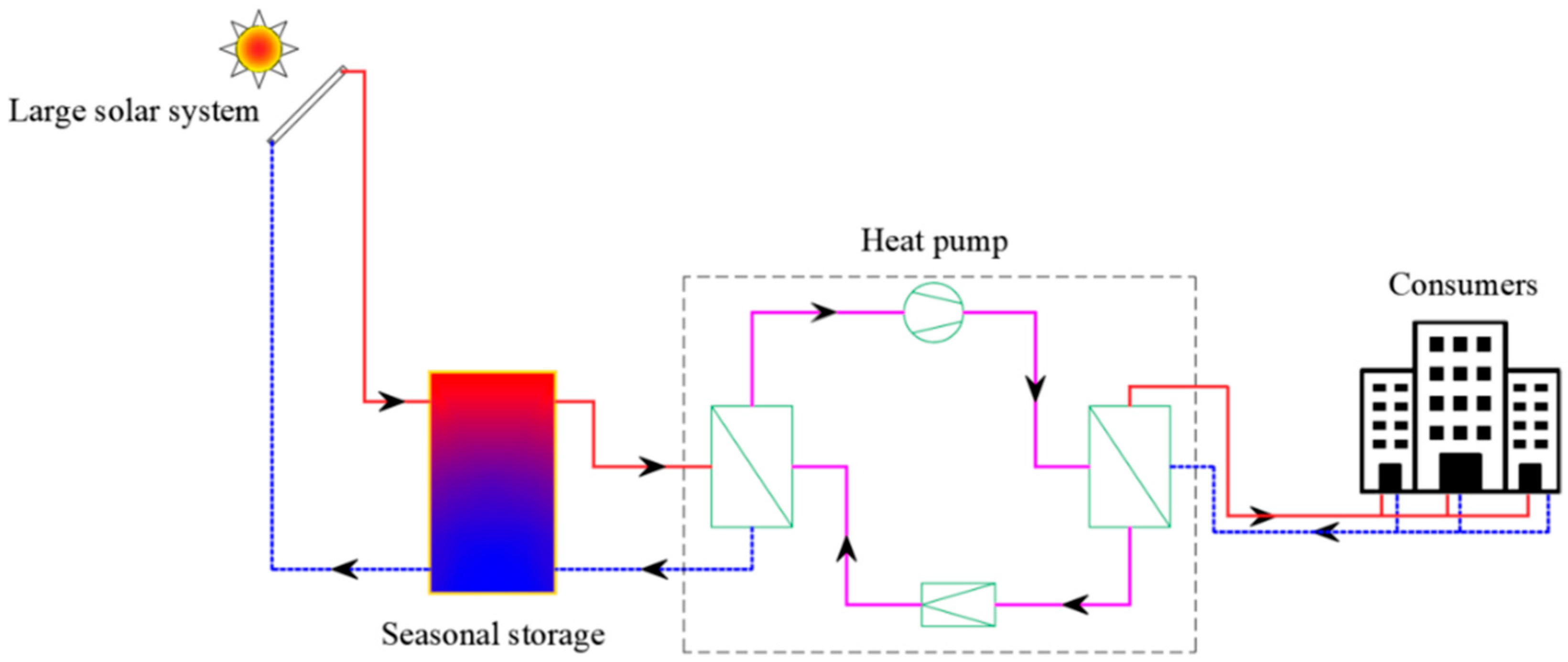
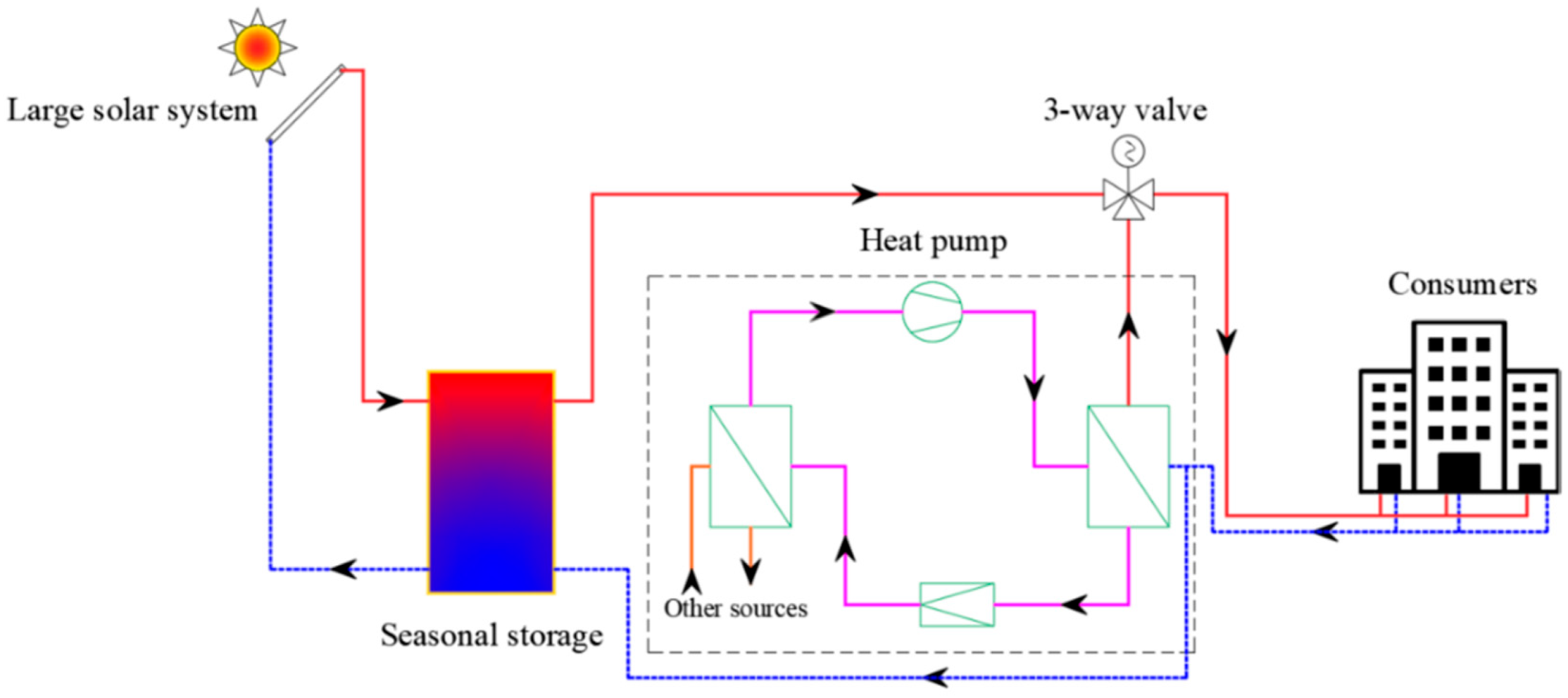
5.4. Coupling Solar Heating Systems and Seasonal Water-Based Storage with Heat Pumps

By coupling solar heating systems and seasonal water-based storage with heat pumps, energy efficiency can be improved [33,98,99,100]. Heat pumps have important advantages, one being related to raising the temperature of the heating agent that delivers heat to consumers and reducing the temperature on the return, thus leading to a more intense thermal stratification. Another advantage is maximizing the storage capacity of the tank. In practice, these advantages are demonstrated by systems in Stuttgart, Marstal, Munich, Eggenstein, Friedrichshafen, and Hamburg [25].
The use of heat pumps that harness thermal energy from the ground coupled with seasonal heat storage brings important savings, with the annual cost being reduced by up to 9% and the energy purchase cost being reduced by 23% [101].
In the configuration where seasonal heat storage systems are used together with heat pumps, the location of the heat pumps can be performed in two ways:
  • The heat pump represents the heat source, and the produced heat will be stored in the tank;
  • The cold source of the heat pump is constituted by the storage tank.
According to the second configuration mode, there is the possibility of connecting in series (Figure 14) or in parallel (Figure 15) [33].
In order to maximize the efficiency of the heating system, the adoption of low-temperature regime heating solutions favors the use of solar energy with seasonal storage, as well as heat pumps. In this case, the COP of the heat pumps will be high because the compressor’s operation will be for a shorter period because the temperature of the heat agent is lower [33].
Due to the fluctuation in the availability of energy from renewable sources, careful control is necessary to optimize its use in district heating systems with seasonal storage through heat pumps. A robust predictive control model for demand response applied to a group of commercial buildings reduces energy costs and helps decision-makers balance between cost and the robustness of solutions to parameter uncertainties [102]. For a university building complex in Parma, Italy, the use of a genetic algorithm implemented in MATLAB to optimize the operation of an energy system composed of renewable energy sources and seasonal heat storage, as developed in [103], showed that the Switch-On Priority strategy, where ground source heat pumps are prioritized for providing necessary heating and cooling, contributes to the reduction in electricity drawn from the grid.
The optimal sizing of a system with multiple energy sources, facilitated by heat pumps and seasonal heat storage [104], is performed in accordance with reducing the total annual costs and carbon dioxide emissions resulting from the system’s operation. Despite the high purchase and installation costs of heat pumps, a significant size is preferred compared to a natural gas boiler. With an average efficiency of the natural gas boiler at 92% and a COP of the heat pump at 2.3 (calculated for an outdoor temperature of −15 °C), the average energy cost is 0.065 EUR/kWh for the boiler and 0.052 EUR/kWh for the heat pump, while the average carbon emissions are 0.258 tons CO2/MWh for the thermal energy generated by the boiler and 0.060 tons CO2/MWh for the energy utilized by the heat pump.

6. Policy Recommendations and Future Directions

In Europe, Denmark is a model of good practice in the implementation and development of seasonal storage systems. In accordance with the energy planning report, Denmark must ensure that regenerative energy is 100% renewable by 2035 and must be completely dependent on the energy supplied by fossil fuels by 2050 [85]. Currently, most heating systems in Denmark operate at temperatures above 80 °C on the flow and 40–45 °C on the return, the tendency being the reduction per flow to around 50 °C, respectively, 25 °C on the return. The advantages of lowering the temperature of the thermal agent in the thermal networks are accounted for in the reduction in heat losses from the pipes, the increase in the installation efficiency (especially in the context of the use of the combustion gas condensation technology), the increase in the COP of the heat pumps, as well as the possibility of integrating sources of low-temperature heat, especially renewable energy sources [105]. Due to the high UE building construction standards (passive or nZEB), the heat requirement continues to decrease, a fact that has led to the implementation of low-temperature heating systems [106].
Although Denmark is an advanced country in the development of district heating, an opinion survey addressed to stakeholders regarding smart heating networks and energy-flexible buildings shows that the renewal and development of social and regulatory measures for flexible energy systems are necessary [107].
In the Netherlands, seasonal storage through aquifers has been facilitated by energy regulations regarding the improvement of energy performance in buildings and environmental regulations in the water industry. In the case of aquifers, the observance of a protection zone around the extraction wells was regulated even though there was a caution on the part of the authorities responsible for underground waters against the seasonal storage of heat through aquifers [108].
Until now, the study of seasonal heat storage has been helped by programs such as IEA SHC Program Task 7, Solarthermie2000, and Solarthermie2000plus [109]. The Heat Roadmap Europe project revealed the importance of implementing district heating systems for the EU, which is the technical solution that can reduce greenhouse gases by 80% by 2050, compared to the level of 1990 [110].

7. Conclusions

The transition to renewable energy sources is one of the main global challenges nowadays, essential for mitigating climate change and reducing dependency on fossil fuels. SESSs are necessary for this transition as they address the mismatch between energy production and consumption, particularly across different seasons. Efficient SESSs can significantly reduce greenhouse gas emissions and enhance the adoption of renewable energy technologies. This review examines the latest advancements in SESSs, particularly their integration into solar district heating systems, and assesses their efficiency, economic feasibility, and environmental benefits.
Advancements in SESS technologies have demonstrated substantial improvements in energy efficiency and performance. Integrated systems have shown that a considerable portion of heating needs can be met through stored solar energy, leading to high efficiency and a marked reduction in CO2 emissions. Technological innovations, such as improved storage materials, advanced insulation methods, and optimized system designs, have further enhanced the effectiveness of SESSs.
Despite the high initial costs associated with SESSs, their long-term economic benefits are evident. Reduced energy costs and lower environmental impacts make these systems economically viable over time. Successful implementations globally indicate that the return on investment for SESSs is promising, reinforcing their potential for widespread adoption.
However, challenges such as significant upfront costs, maintenance difficulties, and heat loss persist. Opportunities for improvement include coupling SESSs with heat pumps, optimizing insulation techniques, and exploring new materials and designs to boost efficiency and lower costs. Future research should focus on optimizing SESS designs, improving thermal retention materials, and developing supportive policies to promote their adoption. International collaboration and knowledge sharing can drive innovation and enhance global energy sustainability.
Working and improving SESS technologies and integrating them into renewable energy systems is a way to achieve more sustainable energy solutions and significantly mitigate the impacts of climate change.

Author Contributions

Conceptualization, M.C.B. and D.H.; methodology, M.C.B. and F.I.B.; investigation, D.H.; data curation, D.H.; writing—D.H., F.I.B. and M.C.B.; writing—review and editing, D.H. and F.I.B.; visualization, D.H.; supervision, M.C.B. and F.I.B. All authors have read and agreed to the published version of the manuscript.

Funding

This research received no external funding.

Conflicts of Interest

The authors declare no conflict of interest.

References

  1. Gong, X.; Shi, R.; Xu, J.; Lin, B. Analyzing Spillover Effects between Carbon and Fossil Energy Markets from a Time-Varying Perspective. Appl. Energy 2021, 285, 116384. [Google Scholar] [CrossRef]
  2. Wu, Q.; Wang, M.; Tian, L. The Market-Linkage of the Volatility Spillover between Traditional Energy Price and Carbon Price on the Realization of Carbon Value of Emission Reduction Behavior. J. Clean. Prod. 2020, 245, 118682. [Google Scholar] [CrossRef]
  3. Hussain, S.A.; Razi, F.; Hewage, K.; Sadiq, R. The Perspective of Energy Poverty and 1st Energy Crisis of Green Transition. Energy 2023, 275, 127487. [Google Scholar] [CrossRef]
  4. European Green Deal—Consilium. Available online: https://www.consilium.europa.eu/en/policies/green-deal/ (accessed on 7 April 2024).
  5. European Parliament Directive 2010/31/EU of the European Parliament and of the Council of 19 May 2010 on the Energy Performance of Buildings. Available online: https://eur-lex.europa.eu/legal-content/en/TXT/?uri=celex%3A32010L0031 (accessed on 30 June 2024).
  6. Report from the Commission to the European Parliament, The Council, The European Economic and Social Committee and the Committee of the Regions State of the Energy Union 2022 (Pursuant to Regulation (EU) 2018/1999 of the Governance of the Energy Union and Climate Action). Available online: https://eur-lex.europa.eu/legal-content/en/TXT/?uri=CELEX%3A52022DC0547&qid=1666595113558 (accessed on 30 June 2024).
  7. Clean Energy—Consilium. Available online: https://www.consilium.europa.eu/en/policies/clean-energy/ (accessed on 7 April 2024).
  8. District Heating: Policies for Cutting Emissions Need Work Says IEA—Energy Post. Available online: https://energypost.eu/district-heating-policies-for-cutting-emissions-need-work-says-iea/ (accessed on 9 April 2024).
  9. Bacquet District Heating and Cooling in the European Union: Overview of Markets and Regulatory Frameworks under the Revised Renewable Energy Directive; Publications Office of the European Union: Copenhagen, Denmark, 2022.
  10. IEA District Heating. Available online: https://www.iea.org/reports/district-heating (accessed on 14 June 2023).
  11. Directive 2012/27/EU of the European Parliament and of the Council of 25 October 2012 on Energy Efficiency, Amending Directives 2009/125/EC and 2010/30/EU and Repealing Directives 2004/8/EC and 2006/32/EC Text with EEA Relevance. 2012. Available online: http://data.europa.eu/eli/dir/2012/27/oj (accessed on 1 April 2024).
  12. Lyden, A.; Brown, C.S.; Kolo, I.; Falcone, G.; Friedrich, D. Seasonal Thermal Energy Storage in Smart Energy Systems: District-Level Applications and Modelling Approaches. Renew. Sustain. Energy Rev. 2022, 167, 112760. [Google Scholar] [CrossRef]
  13. Duffie, J.; Beckman, W. Solar Engineering of Thermal Processes. J. Sol. Energy Eng. 1980, 116, 67–68. [Google Scholar] [CrossRef]
  14. Cabeza, L.F.; Martorell, I.; Miró, L.; Fernández, A.I.; Barreneche, C. Introduction to Thermal Energy Storage (TES) Systems. In Advances in Thermal Energy Storage Systems Methods and Applications; Woodhead Publishing: Cambridge, UK, 2015; pp. 1–28. [Google Scholar] [CrossRef]
  15. Mangold, D.; Deschaintre, L. Seasonal Thermal Energy Storage; IEA SHC Task: Berne, Germany, 2015. [Google Scholar]
  16. Pavlov, G.K.; Olesen, B.W. Thermal Energy Storage—A Review of Concepts and Systems for Heating and Cooling Applications in Buildings: Part 1-Seasonal Storage in the Ground. HVAC R Res. 2012, 18, 515–538. [Google Scholar] [CrossRef]
  17. Dahash, A.; Ochs, F.; Janetti, M.B.; Streicher, W. Advances in Seasonal Thermal Energy Storage for Solar District Heating Applications: A Critical Review on Large-Scale Hot-Water Tank and Pit Thermal Energy Storage Systems. Appl. Energy 2019, 239, 296–315. [Google Scholar] [CrossRef]
  18. Din, I.; Rosen, M.A. Thermal Energy Storage: Systems and Applications, 2nd ed.; John Wiley & Sons: Chichester, UK, 2011. [Google Scholar]
  19. Li, G. Sensible Heat Thermal Storage Energy and Exergy Performance Evaluations. Renew. Sustain. Energy Rev. 2016, 53, 897–923. [Google Scholar] [CrossRef]
  20. Perez-Mora, N.; Bava, F.; Andersen, M.; Bales, C.; Lennermo, G.; Nielsen, C.; Furbo, S.; Martínez-Moll, V. Solar District Heating and Cooling: A Review. Int. J. Energy Res. 2018, 42, 1419–1441. [Google Scholar] [CrossRef]
  21. Alva, G.; Lin, Y.; Fang, G. An Overview of Thermal Energy Storage Systems. Energy 2018, 144, 341–378. [Google Scholar] [CrossRef]
  22. Novo, A.V.; Bayon, J.R.; Castro-Fresno, D.; Rodriguez-Hernandez, J. Review of Seasonal Heat Storage in Large Basins: Water Tanks and Gravel–Water Pits. Appl. Energy 2010, 87, 390–397. [Google Scholar] [CrossRef]
  23. Guelpa, E.; Verda, V. Thermal Energy Storage in District Heating and Cooling Systems: A Review. Appl. Energy 2019, 252, 113474. [Google Scholar] [CrossRef]
  24. Xu, J.; Wang, R.Z.; Li, Y. A Review of Available Technologies for Seasonal Thermal Energy Storage. Sol. Energy 2014, 103, 610–638. [Google Scholar] [CrossRef]
  25. Bott, C.; Dressel, I.; Bayer, P. State-of-Technology Review of Water-Based Closed Seasonal Thermal Energy Storage Systems. Renew. Sustain. Energy Rev. 2019, 113, 109241. [Google Scholar] [CrossRef]
  26. Villasmil, W.; Troxler, M.; Hendry, R.; Schuetz, P.; Worlitschek, J. Control Strategies of Solar Heating Systems Coupled with Seasonal Thermal Energy Storage in Self-Sufficient Buildings. J. Energy Storage 2021, 42, 103069. [Google Scholar] [CrossRef]
  27. Dahash, A.; Ochs, F.; Tosatto, A.; Streicher, W. Toward Efficient Numerical Modeling and Analysis of Large-Scale Thermal Energy Storage for Renewable District Heating. Appl. Energy 2020, 279, 115840. [Google Scholar] [CrossRef]
  28. Gonzalez-Ayala, J.; Blázquez, C.S.; Lagüela, S.; Nieto, I.M. Assesment for Optimal Underground Seasonal Thermal Energy Storage. Energy Convers. Manag. 2024, 308, 118394. [Google Scholar] [CrossRef]
  29. Dolgun, G.K.; Keçebaş, A.; Ertürk, M.; Daşdemir, A. Optimal Insulation of Underground Spherical Tanks for Seasonal Thermal Energy Storage Applications. J. Energy Storage 2023, 69, 107865. [Google Scholar] [CrossRef]
  30. Bauer, D.; Marx, R.; Nußbicker-Lux, J.; Ochs, F.; Heidemann, W.; Müller-Steinhagen, H. German Central Solar Heating Plants with Seasonal Heat Storage. Sol. Energy 2010, 84, 612–623. [Google Scholar] [CrossRef]
  31. Yang, T.; Liu, W.; Kramer, G.J.; Sun, Q. Seasonal Thermal Energy Storage: A Techno-Economic Literature Review. Renew. Sustain. Energy Rev. 2021, 139, 110732. [Google Scholar] [CrossRef]
  32. Guadalfajara, M.; Lozano, M.A.; Serra, L.M. Simple Calculation Tool for Central Solar Heating Plants with Seasonal Storage. Sol. Energy 2015, 120, 72–86. [Google Scholar] [CrossRef]
  33. Hesaraki, A.; Holmberg, S.; Haghighat, F. Seasonal Thermal Energy Storage with Heat Pumps and Low Temperatures in Building Projects—A Comparative Review. Renew. Sustain. Energy Rev. 2015, 43, 1199–1213. [Google Scholar] [CrossRef]
  34. Ochs, F.; Heidemann, W.; Müller-Steinhagen, H. Effective Thermal Conductivity of Moistened Insulation Materials as a Function of Temperature. Int. J. Heat. Mass. Transf. 2008, 51, 539–552. [Google Scholar] [CrossRef]
  35. Kocijel, L.; Mrzljak, V.; Glažar, V. Numerical Analysis of Geometrical and Process Parameters Influence on Temperature Stratification in a Large Volumetric Heat Storage Tank. Energy 2020, 194, 116878. [Google Scholar] [CrossRef]
  36. Arslan, M.; Igci, A.A. Thermal Performance of a Vertical Solar Hot Water Storage Tank with a Mantle Heat Exchanger Depending on the Discharging Operation Parameters. Sol. Energy 2015, 116, 184–204. [Google Scholar] [CrossRef]
  37. Braun, J.E.; Klein, S.A.; Mitchell, J.W. Seasonal Storage of Energy in Solar Heating. Sol. Energy 1981, 26, 403–411. [Google Scholar] [CrossRef]
  38. Drew, M.S.; Selvage, R.B.G. Sizing Procedure and Economic Optimization Methodology for Seasonal Storage Solar Systems. Sol. Energy 1980, 25, 79–83. [Google Scholar] [CrossRef]
  39. Fisch, M.N.; Guigas, M.; Dalenback, J.O. A Review of Large-Scale Solar Heating Systems in Europe. Sol. Energy 1998, 63, 355–366. [Google Scholar] [CrossRef]
  40. Haller, M.Y.; Cruickshank, C.A.; Streicher, W.; Harrison, S.J.; Andersen, E.; Furbo, S. Methods to Determine Stratification Efficiency of Thermal Energy Storage Processes—Review and Theoretical Comparison. Sol. Energy 2009, 83, 1847–1860. [Google Scholar] [CrossRef]
  41. Huang, H.; Xiao, Y.; Lin, J.; Zhou, T.; Liu, Y.; Zhao, Q. Thermal Characteristics of a Seasonal Solar Assisted Heat Pump Heating System with an Underground Tank. Sustain. Cities Soc. 2020, 53, 101910. [Google Scholar] [CrossRef]
  42. Lago, J.; De Ridder, F.; Mazairac, W.; De Schutter, B. A 1-Dimensional Continuous and Smooth Model for Thermally Stratified Storage Tanks Including Mixing and Buoyancy. Appl. Energy 2019, 248, 640–655. [Google Scholar] [CrossRef]
  43. Lottner, V.; Schulz, M.E.; Hahne, E. Solar-Assisted District Heating Plants: Status of the German Programme Solarthermie-2000. Sol. Energy 2000, 69, 449–459. [Google Scholar] [CrossRef]
  44. Lund, P.D. A General Design Methodology for Seasonal Storage Solar Systems. Sol. Energy 1989, 42, 235–251. [Google Scholar] [CrossRef]
  45. Narula, K.; de Oliveira Filho, F.; Villasmil, W.; Patel, M.K. Simulation Method for Assessing Hourly Energy Flows in District Heating System with Seasonal Thermal Energy Storage. Renew. Energy 2020, 151, 1250–1268. [Google Scholar] [CrossRef]
  46. Nicotra, M.; Caldera, M.; Leone, P.; Zanghirella, F. Model-Based Analysis of Thermal Energy Storage for Multiple Temperature Level Heat Supply. Appl. Therm. Eng. 2018, 141, 288–297. [Google Scholar] [CrossRef]
  47. Ochs, F.; Dahash, A.; Tosatto, A.; Bianchi Janetti, M. Techno-Economic Planning and Construction of Cost-Effective Large-Scale Hot Water Thermal Energy Storage for Renewable District Heating Systems. Renew. Energy 2020, 150, 1165–1177. [Google Scholar] [CrossRef]
  48. Raab, S.; Mangold, D.; Müller-Steinhagen, H. Validation of a Computer Model for Solar Assisted District Heating Systems with Seasonal Hot Water Heat Store. Sol. Energy 2005, 79, 531–543. [Google Scholar] [CrossRef]
  49. Raccanello, J.; Rech, S.; Lazzaretto, A. Simplified Dynamic Modeling of Single-Tank Thermal Energy Storage Systems. Energy 2019, 182, 1154–1172. [Google Scholar] [CrossRef]
  50. Rezaie, B.; Reddy, B.V.; Rosen, M.A. Thermodynamic Analysis and the Design of Sensible Thermal Energy Storages. Int. J. Energy Res. 2017, 41, 39–48. [Google Scholar] [CrossRef]
  51. Schmidt, T.; Mangold, D.; Müller-Steinhagen, H. Central Solar Heating Plants with Seasonal Storage in Germany. Sol. Energy 2004, 76, 165–174. [Google Scholar] [CrossRef]
  52. Tanaka, H.; Tomita, T.; Okumiya, M. Feasibility Study of a District Energy System with Seasonal Water Thermal Storage. Sol. Energy 2000, 69, 535–547. [Google Scholar] [CrossRef]
  53. Soloha, R.; Pakere, I.; Blumberga, D. Solar Energy Use in District Heating Systems. A Case Study in Latvia. Energy 2017, 137, 586–594. [Google Scholar] [CrossRef]
  54. Williams, G.T.; Attwater, C.R.; Hooper, F.C. A Design Method to Determine the Optimal Distribution and Amount of Insulation for In-Ground Heat Storage Tanks. Sol. Energy 1980, 24, 471–475. [Google Scholar] [CrossRef]
  55. Rezaie, B.; Reddy, B.V.; Rosen, M.A. Exergy Analysis of Thermal Energy Storage in a District Energy Application. Renew. Energy 2015, 74, 848–854. [Google Scholar] [CrossRef]
  56. Dincer, I. Thermal Energy Storage Systems as a Key Technology in Energy Conservation. Int. J. Energy Res. 2002, 26, 567–588. [Google Scholar] [CrossRef]
  57. Dincer, I. On Thermal Energy Storage Systems and Applications in Buildings. Energy Build. 2002, 34, 377–388. [Google Scholar] [CrossRef]
  58. Dincer, I.; Dost, S.; Li, X. Performance Analyses of Sensible Heat Storage Systems for Thermal Applications. Int. J. Energy Res. 1997, 21, 1157–1171. [Google Scholar] [CrossRef]
  59. Lund, P.D.; Peltola, S.S. SOLCHIPS—A Fast Predesign and Optimization Tool for Solar Heating with Seasonal Storage. Sol. Energy 1992, 48, 291–300. [Google Scholar] [CrossRef]
  60. Campos Celador, A.; Odriozola, M.; Sala, J.M. Implications of the Modelling of Stratified Hot Water Storage Tanks in the Simulation of CHP Plants. Energy Convers. Manag. 2011, 52, 3018–3026. [Google Scholar] [CrossRef]
  61. Wiltshire, R. (Ed.) Advanced District Heating and Cooling (DHC) Systems; Elsevier: Amsterdam, The Netherlands, 2016. [Google Scholar]
  62. Gong, Y.; Ma, G.; Jiang, Y.; Wang, L. Research Progress on the Fifth-Generation District Heating System Based on Heat Pump Technology. J. Build. Eng. 2023, 71, 106533. [Google Scholar] [CrossRef]
  63. Lund, H.; Werner, S.; Wiltshire, R.; Svendsen, S.; Thorsen, J.E.; Hvelplund, F.; Mathiesen, B.V. 4th Generation District Heating (4GDH): Integrating Smart Thermal Grids into Future Sustainable Energy Systems. Energy 2014, 68, 1–11. [Google Scholar] [CrossRef]
  64. Maccarini, A.; Sotnikov, A.; Sommer, T.; Wetter, M.; Sulzer, M.; Afshari, A. Influence of Building Heat Distribution Temperatures on the Energy Performance and Sizing of 5th Generation District Heating and Cooling Networks. Energy 2023, 275, 127457. [Google Scholar] [CrossRef]
  65. Werner, S. International Review of District Heating and Cooling. Energy 2017, 137, 617–631. [Google Scholar] [CrossRef]
  66. Pans, M.A.; Claudio, G.; Eames, P.C. Modelling of 4th Generation District Heating Systems Integrated with Different Thermal Energy Storage Technologies—Methodology. Energy Convers. Manag. 2023, 276, 116545. [Google Scholar] [CrossRef]
  67. Lund, H.; Østergaard, P.A.; Chang, M.; Werner, S.; Svendsen, S.; Sorknæs, P.; Thorsen, J.E.; Hvelplund, F.; Mortensen, B.O.G.; Mathiesen, B.V.; et al. The Status of 4th Generation District Heating: Research and Results. Energy 2018, 164, 147–159. [Google Scholar] [CrossRef]
  68. Pompei, L.; Mannhardt, J.; Nardecchia, F.; Pastore, L.M.; de Santoli, L. A Different Approach to Develop a District Heating Grid Based on the Optimization of Building Clusters. Processes 2022, 10, 1575. [Google Scholar] [CrossRef]
  69. Mozumder, I.; Kumar Thapa, R.; Sevda, S.; Aryal, N.; Prebilič, V.; Može, M.; Golobič, I. Waste-to-Energy Processes as a Municipality-Level Waste Management Strategy: A Case Study of Kočevje, Slovenia. Processes 2024, 12, 1010. [Google Scholar] [CrossRef]
  70. Buffa, S.; Cozzini, M.; D’Antoni, M.; Baratieri, M.; Fedrizzi, R. 5th Generation District Heating and Cooling Systems: A Review of Existing Cases in Europe. Renew. Sustain. Energy Rev. 2019, 104, 504–522. [Google Scholar] [CrossRef]
  71. Volkova, A.; Pakere, I.; Murauskaite, L.; Huang, P.; Lepiksaar, K.; Zhang, X. 5th Generation District Heating and Cooling (5GDHC) Implementation Potential in Urban Areas with Existing District Heating Systems. Energy Rep. 2022, 8, 10037–10047. [Google Scholar] [CrossRef]
  72. Weiss, W.; Spörk-Dür, M. Solar Heat Worldwide. Global Market Development and Trends 2021. Detailed Market Figures 2020; Federal Ministry Republic of Austria, Climate Actions, Environment, Energy, Mobility, Innovation and Technology: Vienna, Austria, 2022. [Google Scholar]
  73. Salvestroni, M.; Pierucci, G.; Pourreza, A.; Fagioli, F.; Taddei, F.; Messeri, M.; De Lucia, M. Design of a Solar District Heating System with Seasonal Storage in Italy. Appl. Therm. Eng. 2021, 197, 117438. [Google Scholar] [CrossRef]
  74. Maximov, S.A.; Mehmood, S.; Friedrich, D. Multi-Objective Optimisation of a Solar District Heating Network with Seasonal Storage for Conditions in Cities of Southern Chile. Sustain. Cities Soc. 2021, 73, 103087. [Google Scholar] [CrossRef]
  75. Tulus, V.; Boer, D.; Cabeza, L.F.; Jiménez, L.; Guillén-Gosálbez, G. Enhanced Thermal Energy Supply via Central Solar Heating Plants with Seasonal Storage: A Multi-Objective Optimization Approach. Appl. Energy 2016, 181, 549–561. [Google Scholar] [CrossRef]
  76. European Commission. Case Study on Solar-Heating Plant in Silkeborg, Denmark; European Commission: Ispra, Italy, 2019.
  77. Vojens District Heating—Solar Heat Europe. Available online: https://solarheateurope.eu/2020/05/19/vojens-district-heating/ (accessed on 9 May 2024).
  78. Solar District Heating—Solar Heat Europe. Available online: https://solarheateurope.eu/about-solar-heat/solar-district-heating/ (accessed on 9 May 2024).
  79. State of Green District Energy. Energy Efficiency for Urban Areas. 2016. Available online: https://ens.dk/sites/ens.dk/files/Globalcooperation/district_energy.pdf/ (accessed on 19 July 2024).
  80. Dronninglund Solar District Heating in Denmark—Copenhagen Centre on Energy Efficiency. Available online: https://c2e2.unepccc.org/kms_object/dronninglund-solar-district-heating-in-denmark/ (accessed on 9 May 2024).
  81. Tschopp, D.; Tian, Z.; Berberich, M.; Fan, J.; Perers, B.; Furbo, S. Large-Scale Solar Thermal Systems in Leading Countries: A Review and Comparative Study of Denmark, China, Germany and Austria. Appl. Energy 2020, 270, 114997. [Google Scholar] [CrossRef]
  82. 15 MW SDH Plant Inaugurated in Latvia—Solar District Heating. Available online: https://www.solar-district-heating.eu/15-mw-sdh-plant-inaugurated-in-latvia/ (accessed on 9 May 2024).
  83. Summary. Available online: https://www.districtenergyaward.org/wp-content/uploads/2021/06/64a576aaa511448999e06bdcbc217e52tmp1.pdf (accessed on 9 May 2024).
  84. 25-Year Heat Supply Contract for 4 MW SDH Plant|Solarthermalworld. Available online: https://solarthermalworld.org/news/25-year-heat-supply-contract-4-mw-sdh-plant/ (accessed on 9 May 2024).
  85. Zhou, X.; Xu, Y.; Zhang, X.; Xu, D.; Linghu, Y.; Guo, H.; Wang, Z.; Chen, H. Large Scale Underground Seasonal Thermal Energy Storage in China. J. Energy Storage 2021, 33, 102026. [Google Scholar] [CrossRef]
  86. Li, X.; Wang, Z.; Li, J.; Yang, M.; Yuan, G.; Bai, Y.; Chen, L.; Xu, T.; Gilmanova, A. Comparison of Control Strategies for a Solar Heating System with Underground Pit Seasonal Storage in the Non-Heating Season. J. Energy Storage 2019, 26, 100963. [Google Scholar] [CrossRef]
  87. Karasu, H.; Dincer, I. Life Cycle Assessment of Integrated Thermal Energy Storage Systems in Buildings: A Case Study in Canada. Energy Build. 2020, 217, 109940. [Google Scholar] [CrossRef]
  88. Epp, B.; Oropeza, M. Solar Heat for Cities. 2019. Available online: http://files.iea-shc.org/public/mrj/d-d2-investor-brochure.pdf (accessed on 14 June 2024).
  89. Hiris, D.P.; Pop, O.G.; Balan, M.C. Preliminary Sizing of Solar District Heating Systems with Seasonal Water Thermal Storage. Heliyon 2022, 8, e08932. [Google Scholar] [CrossRef] [PubMed]
  90. Midttømme, K.; Kocbach, J.; Ramstad, R.K.; Henne, I. Aquifer Thermal Energy Storage (ATES). Tech. Poszuk. Geol. Geoterm. Zrównoważony Rozw. 2017, 2, 203–213. [Google Scholar]
  91. Narula, K.; Filho, F.D.O.; Chambers, J.; Patel, M.K. Simulation and Comparative Assessment of Heating Systems with Tank Thermal Energy Storage—A Swiss Case Study. J. Energy Storage 2020, 32, 101810. [Google Scholar] [CrossRef]
  92. Chang, C.; Leng, G.; Li, C.; Nie, B.; She, X.; Peng, X.; Deng, J. Investigation on Transient Cooling Process in a Water Heat Storage Tank with Inclined Sidewalls. Energy Procedia 2017, 142, 142–147. [Google Scholar] [CrossRef]
  93. Sifnaios, I.; Jensen, A.R.; Furbo, S.; Fan, J. Heat Losses in Water Pit Thermal Energy Storage Systems in the Presence of Groundwater. Appl. Therm. Eng. 2023, 235, 121382. [Google Scholar] [CrossRef]
  94. Mahon, H.; O’Connor, D.; Friedrich, D.; Hughes, B. A Review of Thermal Energy Storage Technologies for Seasonal Loops. Energy 2022, 239, 122207. [Google Scholar] [CrossRef]
  95. Li, X.; Yilmaz, S.; Patel, M.K.; Chambers, J. Techno-Economic Analysis of Fifth-Generation District Heating and Cooling Combined with Seasonal Borehole Thermal Energy Storage. Energy 2023, 285, 129382. [Google Scholar] [CrossRef]
  96. Lu, H.; Tian, P.; He, L. Evaluating the Global Potential of Aquifer Thermal Energy Storage and Determining the Potential Worldwide Hotspots Driven by Socio-Economic, Geo-Hydrologic and Climatic Conditions. Renew. Sustain. Energy Rev. 2019, 112, 788–796. [Google Scholar] [CrossRef]
  97. Kurşun, B. Thermal Stratification Enhancement in Cylindrical and Rectangular Hot Water Tanks with Truncated Cone and Pyramid Shaped Insulation Geometry. Sol. Energy 2018, 169, 512–525. [Google Scholar] [CrossRef]
  98. Hermans, L.; Haesen, R.; Uytterhoeven, A.; Peere, W.; Boydens, W.; Helsen, L. Pre-Design of Collective Residential Solar Districts with Seasonal Thermal Energy Storage: Importance of Level of Detail. Appl. Therm. Eng. 2023, 226, 120203. [Google Scholar] [CrossRef]
  99. Kim, M.H.; Kim, D.W.; Lee, D.W.; Heo, J. Energy Conservation Performance of a Solar Thermal and Seasonal Thermal Energy Storage-Based Renewable Energy Convergence System for Glass Greenhouses. Case Stud. Therm. Eng. 2023, 44, 102895. [Google Scholar] [CrossRef]
  100. Xu, B.; Zhang, T.; Wang, S.; Chen, Z. Dynamic Characteristics and Energy Efficiency Evaluation of a Novel Solar Seasonal Thermal Storage—Heating System. Appl. Therm. Eng. 2023, 234, 121223. [Google Scholar] [CrossRef]
  101. Zhou, Y.; Min, C.; Wang, K.; Xie, L.; Fan, Y. Optimization of Integrated Energy Systems Considering Seasonal Thermal Energy Storage. J. Energy Storage 2023, 71, 108094. [Google Scholar] [CrossRef]
  102. Hosseini, S.M.; Carli, R.; Dotoli, M. Robust Optimal Demand Response of Energy-Efficient Commercial Buildings. In Proceedings of the 2022 European Control Conference, ECC 2022, London, UK, 12–15 July 2022; pp. 1606–1609. [Google Scholar] [CrossRef]
  103. Bahlawan, H.; Losi, E.; Manservigi, L.; Morini, M.; Pinelli, M.; Spina, P.R.; Venturini, M. Optimization of a Renewable Energy Plant with Seasonal Energy Storage for the Transition towards 100% Renewable Energy Supply. Renew. Energy 2022, 198, 1296–1306. [Google Scholar] [CrossRef]
  104. Gabrielli, P.; Gazzani, M.; Martelli, E.; Mazzotti, M. Optimal Design of Multi-Energy Systems with Seasonal Storage. Appl. Energy 2018, 219, 408–424. [Google Scholar] [CrossRef]
  105. Danish Energy Agency, Regulation and Planning of District Heating in Denmark. 2015. Available online: https://ens.dk/sites/ens.dk/files/contents/material/file/regulation_and_planning_of_district_heating_in_denmark.pdf (accessed on 28 June 2024).
  106. Haslinger, E.; Turewicz, V.; Hammer, A.; Götzl, G. Assessment of Deep and Shallow Geothermal Resources and Measurement of Waste Heat Potentials from Industrial Processes for Supplying Renewable Heat for Industry and Urban Quarters. Processes 2022, 10, 1125. [Google Scholar] [CrossRef]
  107. Johansen, K.; Werner, S. Something Is Sustainable in the State of Denmark: A Review of the Danish District Heating Sector. Renew. Sustain. Energy Rev. 2022, 158, 112117. [Google Scholar] [CrossRef]
  108. Bolton, R.; Cameron, L.; Kerr, N.; Winskel, M.; Desguers, T. Seasonal Thermal Energy Storage as a Complementary Technology: Case Study Insights from Denmark and The Netherlands. J. Energy Storage 2023, 73, 109249. [Google Scholar] [CrossRef]
  109. Persson, J.; Westermark, M. Low-Energy Buildings and Seasonal Thermal Energy Storages from a Behavioral Economics Perspective. Appl. Energy 2013, 112, 975–980. [Google Scholar] [CrossRef]
  110. Connolly, D.; Lund, H.; Mathiesen, B.V.; Werner, S.; Möller, B.; Persson, U.; Boermans, T.; Trier, D.; Østergaard, P.A.; Nielsen, S. Heat Roadmap Europe: Combining District Heating with Heat Savings to Decarbonise the EU Energy System. Energy Policy 2014, 65, 475–489. [Google Scholar] [CrossRef]
Figure 1. The share of energy sources used in the world by district heating.
Processes 12 01623 g001
Figure 2. The share of energy sources used in the EU by centralized heating systems for the year 2018.
Processes 12 01623 g002
Figure 3. Evolution of publications in the field of solar district heating with seasonal heat storage.
Processes 12 01623 g003
Figure 4. Word-cloud diagram with keywords extracted from the bibliographical references cited in this study.
Processes 12 01623 g004
Figure 5. The advantages and disadvantages of seasonal thermal energy storage systems.
Processes 12 01623 g005
Figure 6. The characteristic temperatures and energy efficiency for each generation of district heating.
Processes 12 01623 g006
Figure 7. Evolution of generations of district heating systems.
Processes 12 01623 g007
Figure 8. The solar district heating system in Silkeborg, Denmark.
Processes 12 01623 g008
Figure 9. The solar heating and seasonal heat storage system in Vojens, Denmark.
Processes 12 01623 g009
Figure 10. Solar collectors and seasonal storage for the solar heating system in Dronninglund.
Processes 12 01623 g010
Figure 11. The centralized solar heating system in Salaspils, Latvia.
Processes 12 01623 g011
Figure 12. The solar heating system in Friesach, Austria.
Processes 12 01623 g012
Figure 13. Non-uniform optimal insulation distribution.
Processes 12 01623 g013
Figure 14. Series connection of the seasonal storage tank and the heat pump.
Processes 12 01623 g014
Figure 15. Parallel connection of the seasonal storage tank and the heat pump.
Processes 12 01623 g015
Table 1. The characteristics of the main concepts of seasonal thermal energy storage.
ParameterU.M.TanksPitsBoreholesAquifers
The storage medium[-]watergravel–watersoilsand–water
Energy density[kWh/m3]60–8030–5015–3030–40
Equivalent storage water volume[m3 water]11.3–23–52–3
Specific costs[EUR/m3]30–50030–50050–15040–100
Depth/height[m]5–15 m5–15 m20–50 m30–200 m
Geological conditions[-]stable soilstable soildrillable landaquifer layer
Table 2. Characteristics of seasonal heat storage technologies.
FeaturesTanksPitsBoreholesAquifers
Structurepre-stressed reinforced concrete or stainless steela load-bearing frame is not required for constructiondeep vertical U-type drills made in the ground or rocksgeological structures containing groundwater
Insulationthick layer of insulationpits are coveringnecessary at the top of the well.complete thermal insulation is not possible
Placeany placelimited choice of locationslimited choice of locationslimited choice of location placement.
Maintenance and repairpossible with conventional technologiesdifficult/impossibledifficult/impossibledifficult/impossible
Special requirementdesigned regardless of the necessary geometrythe excavations covered with polymer material sheets welded on the lateral sides and the bottom of the pitdrilling is carried out at depths of 30–200 mpermission from the responsible authorities for groundwater
Table 3. Geometric characteristics of some seasonal storage tank in Europe.
CityCountryV
[m3]
A
[m2]
d
[m]
h
[m]
A/V
[1/m]
h/d
[-]
Ref.
HamburgDEU4500165025.710.70.370.42[17]
FriedrichshafenDEU12,000279632.419.40.230.60[17]
IlmenauDEU3002627.280.871.11[17]
HanoverDEU275011351911.10.410.58[17]
AttenkirchenDEU5003508.980.700.90[17]
CrailsheimDEU4803626.314.50.752.30[17]
MunichDEU6000180024.616.10.300.65[17]
StudsvikSWE1200450--0.38-[34]
LombohovSWE10,0001750--0.18-[34]
RottweilDEU5974701350.790.38[25]
CosenzaITA500-107.3-0.73[25]
NeuchatelCHE1000107514.616.150.451.1[25]
RiseDNK4000144520130.360.65[25]
MühldorfDEU16.442.71.872.63.8[25]
VaulruzCHE3517633130.56.21.80.22[25]
Table 4. Location and geometric shape of specific seasonal storage tanks in Europe.
CityCountryPlacementGeometric Shape
RottweilDEUpartially buriedcylinder
CosenzaITAburiedcylinder
FriedrichshafenDEUpartially buriedcylinder
NeuchatelCHE-cylinder
IlmenauDEUabove groundcylinder
HannoverDEUburiedcylinder
RiseDNKabove groundcylinder
MunichDEUpartially buriedcylinder
HamburgDEUburiedcylinder
MühldorfDEUabove groundcylinder
VaulruzCHEburiedtruncated cone
Table 5. Structural element materials and their thickness specific to seasonal storage tanks in Europe.
CityCountryThe Material of the Structural ElementThe Thickness of the Structural Material
[m]
RottweilDEUconcrete0.25
CosenzaITAconcrete0.2–0.5
FriedrichshafenDEUconcrete0.3
NeuchatelCHEconcrete-
IlmenauDEUglass fiber reinforced plastic0.02 (0.17)
HannoverDEUconcrete0.3
RiseDNKsteel-
MunichDEUconcrete0.16
HamburgDEUconcrete0.3
MühldorfDEUstainless steel0.2
VaulruzCHE--
HoerbyDNKconcrete-
HerlevDNKconcrete and sheet steel-
IngelstadSWEconcrete-
Table 6. Material and thickness of insulation specific to some seasonal storage tanks in Europe.
CityCountryThe Insulating Material of the BaseThe Insulating Material of the WallsThe Insulating Material of the Upper PartInsulation Thickness [m]
RottweilDEUnon-insulatedmineral fibersmineral fibers-
CosenzaITAexpanded glass foam gravelexpanded glass foam gravelexpanded glass foam gravel0.2
FriedrichshafenDEUnon-insulatedmineral fibersmineral fibers0.3
NeuchatelCHEnon-insulatedmineral fibers + XPSmineral fibers + XPS-
IlmenauDEUnon-insulatedpolyurethane foampolyurethane foam-
HannoverDEUnon-insulatedexpanded glass granulesexpanded glass granules-
RiseDNKnon-insulatedmineral fibersmineral fibers-
MunichDEUexpanded glass foam gravelexpanded glass granulesexpanded glass granules-
HamburgDEUnon-insulatedmineral fibersmineral fibers0.3
MühldorfDEUperliteperliteperlite-
VaulruzCHEnon-insulatedEPSEPS-
Table 7. The constructive parameters identified in the literature.
Ref.VA/VGeometryh/dLocation TypeStructureInsulation
[21]
[36]
[25]
[37]
[17]
[27]
[38]
[39]
[32]
[23]
[40]
[41]
[35]
[42]
[19]
[43]
[44]
[45]
[46]
[22]
[34]
[47]
[16]
[48]
[49]
[50]
[51]
[52]
[24]
[33]
[39]
[53]
[54]
Table 8. Global energy efficiency values of seasonal storage tanks identified in the literature.
Ref.Energetic Efficiency [%]Evaluation Method
[56]90simulation
[57]90simulation
[58]90simulation
[32]88simulation
[23]70-
[45]66.4measurement
[45]65.7simulation
[47](72–88)simulation
[48]71.2measurement
[55]60measurement
[52]90simulation
[59](85–90)simulation
Table 9. The efficiency parameters identified in the literature.
Ref.ηstηdesηchrψstStrMIXAspects StudiedMain Finding
[36] (0–1)energy efficiencymeasures to improve efficiency
[25] state of the artincreasing efficiency with multi-store combines
[60] exergy efficiencyexergy destruction influences the economic feasibility
[17](0–1)state of the arthigher stratification for tanks than pits
[27] (0.14–0.55)energy efficiencyhigher stratification for tank than pit in Dronninglund
[56] energy and exergy efficiencyexergetic analyses are more relevant than energetic ones
[57] energy and exergy efficiencyexergetic analyses are more relevant than energetic ones
[58] energy and exergy efficiencyexergetic analyses are more relevant than energetic ones
[32] evaluation of solar heating systemslarger storage tanks are more efficient
[23] state of the artthermal energy storage has more advantages than batteries
[40](0–1)state of the artseparating the effects due to heat losses from those of the mixture
[19] state of the artsensible thermal energy storage is cheap and easy to control
[45] feasibility of solar heating systemsmaking a modelling tool for multi-energy heating system
[48] model validation for district heatingmodel was validated, the deviations are less than 5%
[49] thermal behavior of storage tanksefficiency is higher in open systems (one-dimensional models)
[55] Friedrichshafen district heatingoverall energy efficiencies (60%) and exergy efficiencies (19%)
[51] district heating technologiesnew concepts for seasonal heat storage
[53] district solar heating in Latviathe specific costs for solar district heating are close to natural gas
[52] feasibility of solar heating systemsseasonal heat storage indicates energy savings of 26%
[59] predesign and optimization tooloptimizations can reduce the annual energy price by 50%
Table 10. The most important countries and regions contributing to solar district heating by the end of 2021 [72].
CountryCollector SurfaceNumber of SystemsThermal Power
[-][m2][-][MW]
DNK1,608,4011251126
CHN390,00041279
DEU117,0004581.5
AUT49,0002234
OTH European45,000728.1
SAU41,000125.4
SWE39,0002423.9
POL20,000812.5
FRA16,000811.4
NLD12,00037.5
CHE11,00077.3
Asia w/o China700034.5
USA/CAN600022.8
ZAF400020.8
ITA200010.7
Table 11. The methodologies used in the case studies.
Case StudyRef.Evaluation Method
Silkeborg, Denmark[76]desk search, field visits, and interviews with project owners
Vojens, Denmark[77,78,79]desk search
Dronninglund Fjernvarme, Denmark[80,81]design and operation
Salaspils, Letonia[82,83]interviews with project owners, design and operation
Friesach, Austria[84]interviews with project owners, design and operation
Zhangjiakou, China[85,86]design and simulation
Drake Landing Solar Community, Canada[87]design and simulation
Langkazi, Tibet[81,88]design and operation
Disclaimer/Publisher’s Note: The statements, opinions and data contained in all publications are solely those of the individual author(s) and contributor(s) and not of MDPI and/or the editor(s). MDPI and/or the editor(s) disclaim responsibility for any injury to people or property resulting from any ideas, methods, instructions or products referred to in the content.

