Abstract
The newly developed computational fluid dynamics, transport, and chemical kinetics-based monolith catalyst dimensioning methodology consists of the following steps: (i) initial calculations, which generate some of the data, e.g., average inlet fluid velocity used in the (ii) computational fluid dynamics (CFD) modelling, which uses the laminar flow interface and the transport of diluted species interface while the user has to provide the kinetics of the reactions; (iii) the model order reduction uses a modified version of the plug flow reactor model and the linear pressure variation model; and (iv) the dimensioning optimization algorithm extracts the optimal monolith catalyst’s channel geometry, which satisfies the user’s performance constraints and reduces material consumption. Therefore, the methodology enables chemical engineers to quickly and efficiently design and dimension monolith catalysts for many different applications in an environmentally friendly way, which enables them to reduce both the material and operating costs while maintaining sufficient catalyst performance and, therefore, achieve its cost-effective performance.
1. Introduction
The advantages of structured catalysts over fixed-bed reactors are their lower maldistribution and pressure drop [1], which is why they are widely used in chemical industry. The monolith catalysts have been in use in chemical engineering applications both for gas phase and gas–liquid reactions [2,3]. The gas phase reactions include (i) emission control of CO, unburned hydrocarbons (HC) and nitrogen oxides (NOX) [4,5,6], (ii) catalytic combustion [7,8,9], (iii) steam reforming [10,11,12], (iv) methanation [13,14], (v) hydrogenation/dehydrogenation [15,16], (vi) oxidation [17,18,19], and (vii) water gas shift reaction [20,21]. Since many industrial processes depend on monolith catalysts, their optimized design, accurate modelling, effective performance, and reduced material toxicity are essential in multiple sectors of our society.
The computational fluid dynamics (CFD) modelling approach has been widely used to simulate processes of mass transfer and chemical kinetics inside monolith catalysts. Many studies have focused on either varying design/geometry [22,23,24] and/or predicting catalyst performance [25,26,27]. However, not many authors, e.g., [28], have used or combined their CFD results with one-dimensional (1D) monolith catalyst modelling. A one-dimensional modelling approach is often used for optimizing monolith design and configurations by manufactures [29]. Model order reduction (MOR) methodology could help monolith designers by converting often computationally costly CFD modelling approach to simple 1D model calculations.
Multiple reduced order models for modelling of washcoated monolithic catalysts are presented in the available literature. However, most of the reduced order models are quite complex with multiple partial differential equations [30], transverse averaging using the Lyapunov–Schmidt method, look-up tables [31], and/or multiple matrices, e.g., the Thiele matrix [32]. Our approach, on the other hand, used only two simple algebraic equations to model the cross-sectional average (perpendicular to the flow direction) values of concentration and pressure (computed via CFD approach), respectively.
Some of the commonly used active catalyst materials are expensive, e.g., Pt [33], are toxic, e.g., V2O5 [34], are hard or impossible to recycle [35], and/or have no adequate alternative materials (e.g., Pt). Therefore, a reduction in the use of these crucial materials would reduce the manufacturing cost and the negative environmental impact of the monolith catalysts, considering their whole life cycle.
Chemical engineers who design and dimension a monolithic catalytic converter usually know the composition and the volumetric flow rate (Q) of their gas mixtures, the minimal required monolith catalyst performance (usually conversion of specific species or selectivity), maximal allowed pressure drop across the monolith channels, and the space constrains dedicated to the catalyst. Therefore, these elements are the input parameters for the developed dimensioning methodology. The chemical kinetics of the reactions occurring in the monolith catalyst should also be known in the form of rate law(s), as are, for example, for some selective catalytic reduction denitrification (SCR-deNOX) catalysts which use ammonia as a reducing agent [24,36,37].
The usefulness of the CFD-based monolith catalyst dimensioning methodology was illustrated on a hypothetical case of an automotive SCR-deNOX washcoated monolithic catalyst (WMC) for the removal of nitrogen oxides from flue gasses emitted by a personal vehicle with a hydrogen-powered internal combustion engine drivetrain.
2. Methods
The monolith catalyst dimensioning methodology consists of four main consecutive steps: (i) initial calculations, (ii) CFD modelling, (iii) model order reduction; and (iv) the dimensioning optimization algorithm.
2.1. Initial Calculations
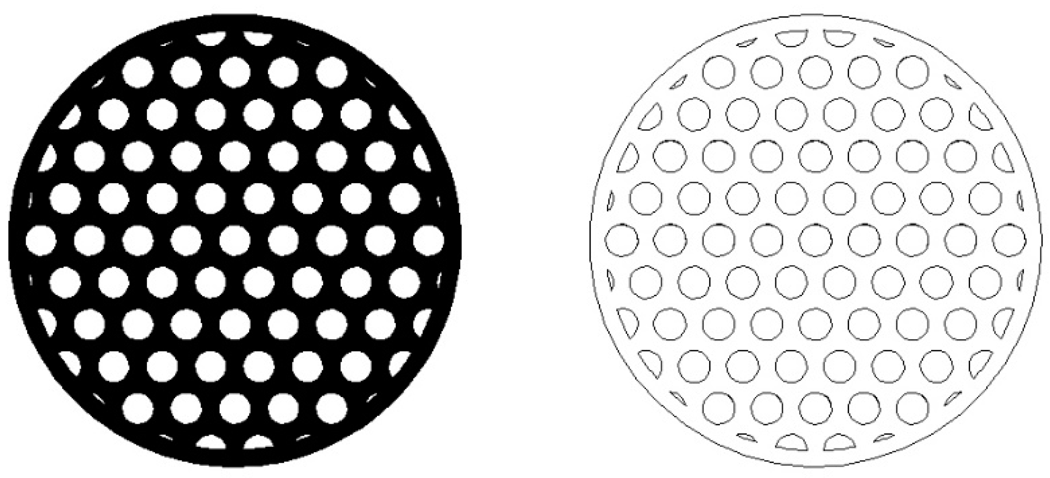
The typical automotive cylindrical monoliths have diameters (Dm) of 100 mm and lengths (Lm) of 150 mm [38]. These dimensions were also considered in our example of designing and dimensioning of an automotive SCR-deNOX catalyst. The share of effective flow area (Sheff) was assumed to be equal to 0.6 to account for the thickness of the monolith’s walls which enable its structural integrity, load bearing capacity, and mechanical resistivity. The arrangement of the channels in the monolith catalyst was expected to follow the hexagonal-lattice-based circle packing pattern (of equally sized circles), which has been used in monoliths [39] and can be seen in Figure 1 [39]. The hexagonal-lattice-based circle packing is the densest circle packing in the plane with a packing density equal to [40]. This circle packing density is of course a theoretical limit, which, if applied to our case, would mean that the monolith’s walls would have zero thickness and the monolith would have no extra material near its outer edges. Therefore, a considerably lower value than the 0.9069 theoretical limit was selected for the share of effective flow area (Sheff).

Figure 1.
Cross-section (left) and drawing (right) of a cylindrical monolith with the hexagonal-lattice-based packing of cylindrical channels.
The average fluid velocity (uav) flowing through the effective flow area (Aeff) was, therefore, determined using Equation (1).
In case of the selected volumetric flow rate of 3.3 × 10⁻² m3/s, the average velocity is, in this case, equal to 7 m/s. This value of velocity was used as an input for the subsequent CFD studies.
The radii (R) of the individual cylindrical monolith channels were determined with Equation (2), where N is the number of monolith channels and varied from 600 to 6000 by steps of 50 (109 different radii, see Table A1).
The channels’ walls are assumed to be coated with a uniformly thick layer of high surface area washcoat that contains dispersed active catalyst material [41].
2.2. CFD Modelling
The CFD studies were conducted using the COMSOL Multiphysics® (version 5.1, COMSOL S.r.l., Brescia, Italy) simulation platform with two-dimensional (2D) axisymmetric stationary studies employing the laminar flow interface (spf, [42]) and the transport of diluted species interface (tds, [43]).
The Navier–Stokes equation of single-phase steady state incompressible laminar flow is Equation (3), where ρ denotes fluid density, u is the velocity, p is the pressure, I is the identity matrix, μ is the dynamic viscosity, and F represents the volume forces.
Equation (4) is the continuity equation.
The inflow at the inlet of a single cylindrical catalyst channel was selected to be the laminar inflow with a parabolic velocity profile. The working fluid was assumed to be produced during combustion of hydrogen with air and to enter the monolith channel at the temperature 300 °C, which is within the optimal operating temperature range of multiple commercial deNOX catalysts [44]. The fluid’s density was determined with the ideal gas law and the calculation of the average gas mixture’s molecular weight, while viscosity was determined with the method of Wilke [45]. For the combustion products of hydrogen (with air) at the equivalence ratio of 1.15 (see Table B.1 of Voglar et al. [46]) at 300 °C, the destiny equalled 0.5319 kg/m3 and the dynamic viscosity was 2.597 × 10⁻⁵ Pa·s. In all of the studies, the average inlet fluid velocity was set to 7 m/s. The outlet had the pressure (0 Pa) boundary condition with suppressed backflow.
The transport of diluted species interface models the chemical species’ transport through diffusion (Fick’s second law) and convection. This Equation (5) is used, where Di denotes the diffusion coefficient of the species i, ci is the concentration of the species i, and Ri is the reaction rate expression of the species i.
The mass conservation equation for one or more chemical species i has a form of Equation (6), where Ni denotes the flux of the species i.
The velocity field was inserted from the laminar flow interface (spf) calculations. Diffusion coefficients of both species A and B were set to 1 × 10⁻⁵ m2/s, which is within the range typical for gaseous species [47].
The initial (inlet) concentration of species A, simulating species of nitrogen oxides (NOX), was set to 1 × 10⁻² mol/m3, since the usual NOX level is around 500 ppm [48,49], which equals to 1.06 × 10⁻² mol/m3 (at 300 °C). The inlet concentration of species B, representing the molecular nitrogen (N2) and water vapour (H2O) produced by the SCR-deNOX reactions, was set to 0 mol/m3.
This simple chemical reaction (Equation (7)) was assumed to take place at the fluid–cylinder wall interface (inside the monolith catalyst channel).
The reaction was introduced as a flux boundary condition within the transport of diluted species interface (tds). Since the reaction is equimolar, it does not affect the flow regime by producing additional molecules and also simulates well the three main SCR-deNOX reactions (standard, fast, and NO2 SCR reaction), which have their molar ratio between products and reactants close to one (from 1.111 to 1.357).
The reaction rate (r) equation is this Equation (8).
The reaction constant k has a unit of m/s because it models a surface reaction. The value of the reaction rate coefficient, k, was set to 1 × 10⁶ m/s.
The inward fluxes of the species A and B (RA and RB) at the cylinder wall were determined with Equations (9) and (10).
Our CFD studies modelled the external mass transfer effects while the internal mass transfer (through the pores of the catalyst material) was neglected. The reaction kinetics did not present the majority of the resistance, while the transport of species to the catalyst surface presented the main conversion limitation.
The computational domain’s meshing was conducted with the selection of a physics-controlled mesh with a normal element size. Since our paper introduces a new catalyst dimensioning methodology and is not focused on generating accurate results, a grid independence study was, in our case, not performed. However, a grid independence study, verification, and experimental validation (on at least a couple of different monolith geometries) are advised to be carried out when our methodology is utilized in a real case of dimensioning of a monolith catalyst.
The temperature of the system was assumed to be constant 573.15 K (300 °C). The system was, therefore, adiabatic and isothermal, which is consistent with the other numerical studies, e.g., [50,51].
2.3. Model Order Reduction
When we extracted the relevant CFD data (pressure drop, concentrations of species), we continued our work with model order reduction (MOR) to simplify and enable our further methodological steps. The model order reduction methodology was applied to the CDF results. The model for determining the average concentration of species A inside the monolith channel varying with the monolith length (l) is the slightly modified version of the standard one-dimensional plug flow reactor (PFR) model (Equation (11)) [52], where cA,in is the inlet concentration of species A and kc is the model constant, which describes the mass transport phenomena (by convection and diffusion) and reaction kinetics.
The model for the pressure variation across the channel’s length is well known to be linear [53], so Equation (12) was used, where pin is the inlet pressure and kp represents the model constant. We will name this model the linear pressure variation (LPV) model.
The values of the model constants were extracted from the CFD results, where radially averaged values of the concentration of species A and pressure were sampled at the (equally spaced) nine lengths of the monolith channel. The model fitting was performed in the Python programming language (version 3.8.10) using the Spyder (version 5) integrated development environment (IDE).
2.4. Dimensioning Optimization Algorithm
The cost-effective monolith catalyst performance optimization algorithm was written in the Python programming language using the Spyder integrated development environment (IDE).
At this stage, the user has to provide the algorithm with two of the most relevant catalyst performance indicators: desired conversion (in our case 0.95 [54]) and maximal allowed pressure drop (in our case 560 Pa [55]).
The conversion of species A (ConA) is defined in Equation (13), where cA,in and cA,out are the inlet and outlet concentrations of the species A, respectively.
The algorithm firstly extracted all of the geometries with conversions equal or higher than the desired conversion. The leftover channels would have to be longer than the initial length limitation (150 mm) to satisfy the conversion criterium. Secondly, the algorithm used the PFR model to calculate the optimal channel lengths (L) with conversions equal to the desired conversion and applied the LPV model to determine the corresponding pressure drops (Δp). The next step was the elimination of the channels with too large pressure drops. Finally, the cost of the monolith catalyst was considered.
The cost of washcoated monolith catalyst manufacturing is correlated with the quantity of the active catalyst material used, since it usually contains expansive materials, e.g., precious metals [56]. The volume (V) of the used active catalyst material, which is uniformly coated in a thin layer (of thickness δ) on the inner surface of the individual cylindrical monolith channel, can be determined with Equation (14).
In cases of thin coatings (δ << R), the volume of the active catalyst material for an individual catalyst channel can be estimated using Equation (15).
Since the coating thickness (δ) is assumed to be constant for a specific type of an active catalyst material, the cost of the coating material for an individual catalyst channel is proportional to the product of the radius (R) and length (L) of the cylindrical monolith channel. Because the monolith catalyst has multiple (N) parallel cylindrical channels coated with an active catalyst material, the cost of the monolith catalyst (Cost) can be estimated with Equation (16).
The last step of the algorithm involves the optimization of the cost-effectiveness of the monolith catalyst. After calculating the estimated cost for the active catalyst material, the algorithm finds the case with the minimal cost from the already sifted geometries with adequate performance both in terms of conversion and pressure drop. Therefore, the algorithm enables chemical engineers to find the cost-effectiveness-optimized monolith catalyst geometry which satisfies their performance and space constraint criteria.
3. Results and Discussion
The initial assumptions of our hypothetical case, along with the results of the initial calculations, are already presented in Section 2. The main aim of the initial calculations was to extract the relevant data to be used as the boundary conditions of the following CFD studies.
The CFD studies were performed on the geometries of cylindrical monolith channels with lengths of 150 mm and 109 different radii (R) varying from 0.50 mm up to 1.58 mm. The Reynolds numbers (Re) of our CFD studies varied between 143 and 453 (see Table A1).
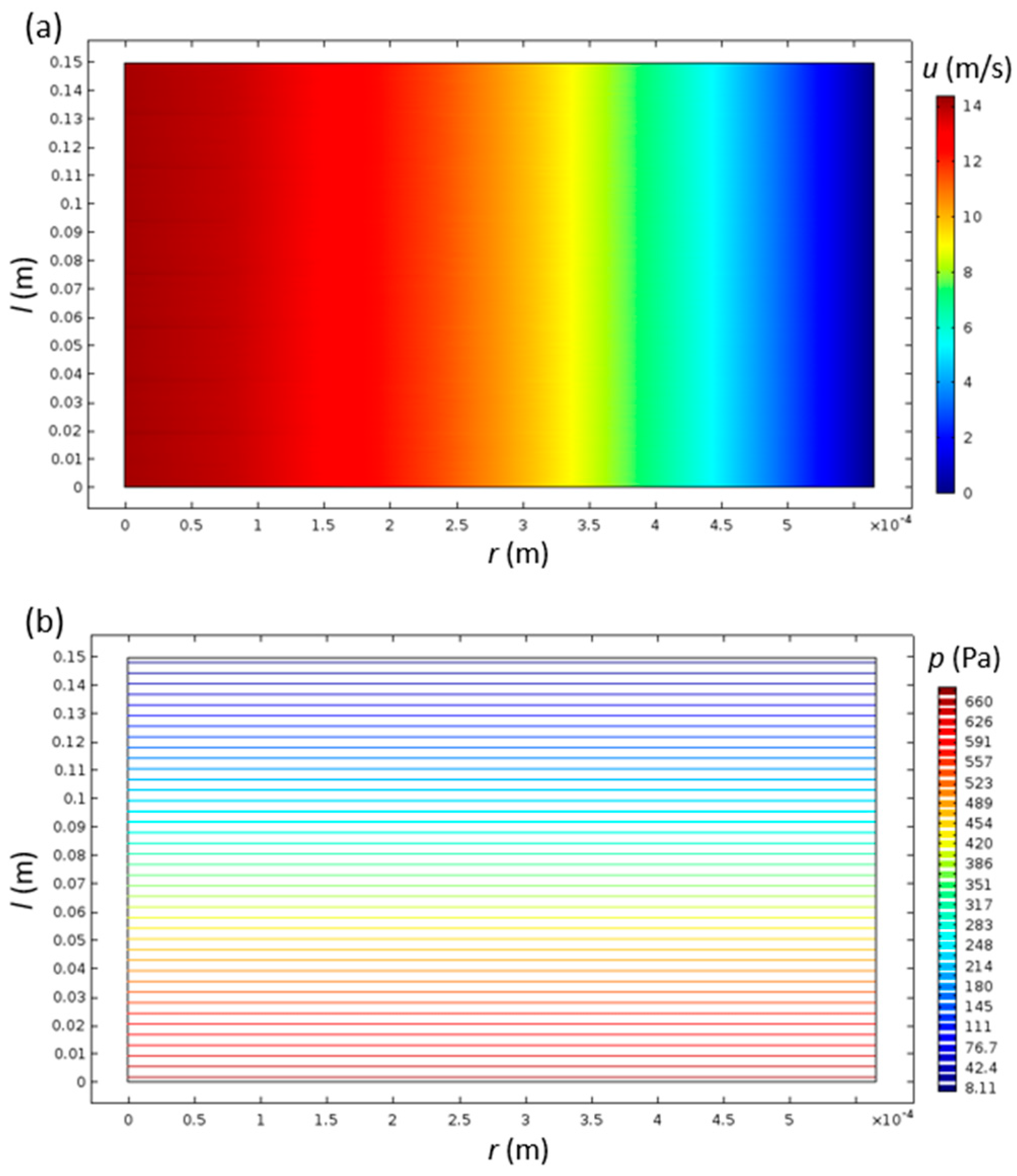
The velocity field was, as expected, unchanging with the axial direction of the channel, since the inlet velocity profile inserted as the boundary condition was already parabolic—a fully developed laminar flow (Figure 2a). The pressure inside the monolith channels monotonically decreased with increasing channel length, while it had close to zero variation in the radial direction (Figure 2b). This type of spatial pressure variation is typical for laminar flow inside a channel.

Figure 2.
Velocity (a) and pressure (b) distributions inside the cylindrical monolith catalyst channel with R = 0.565 and L = 150 mm.
The concentrations of species A and B have high gradients near the inlet, while they settle to a more uniform distribution at the outlet (Figure 3). Since both of the diffusion coefficients are the same, the contours of both of the species are inverse to each other, as expected.
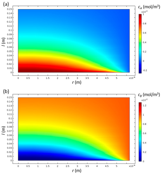
Figure 3.
Contours of concentrations of species A (a) and B (b) inside the cylindrical monolith catalyst channel with R = 0.565 and L = 150 mm.
The conversions of species A varied from 0.4540 (at R = 1.581) to 0.9812 (at R = 0.500), while the pressure drops varied from 88 Pa (at R = 1.581) to 874 Pa (at R = 0.500). Small diameter channels exhibited high conversion accompanied with high pressure drop, and large diameter channels had low conversion with low pressure drop. Therefore, the trade-off between a high conversion and a high pressure drop is clearly present (Table A1), so the engineers have to be aware of it and consider it during the design and dimensioning of the monolith catalysts.
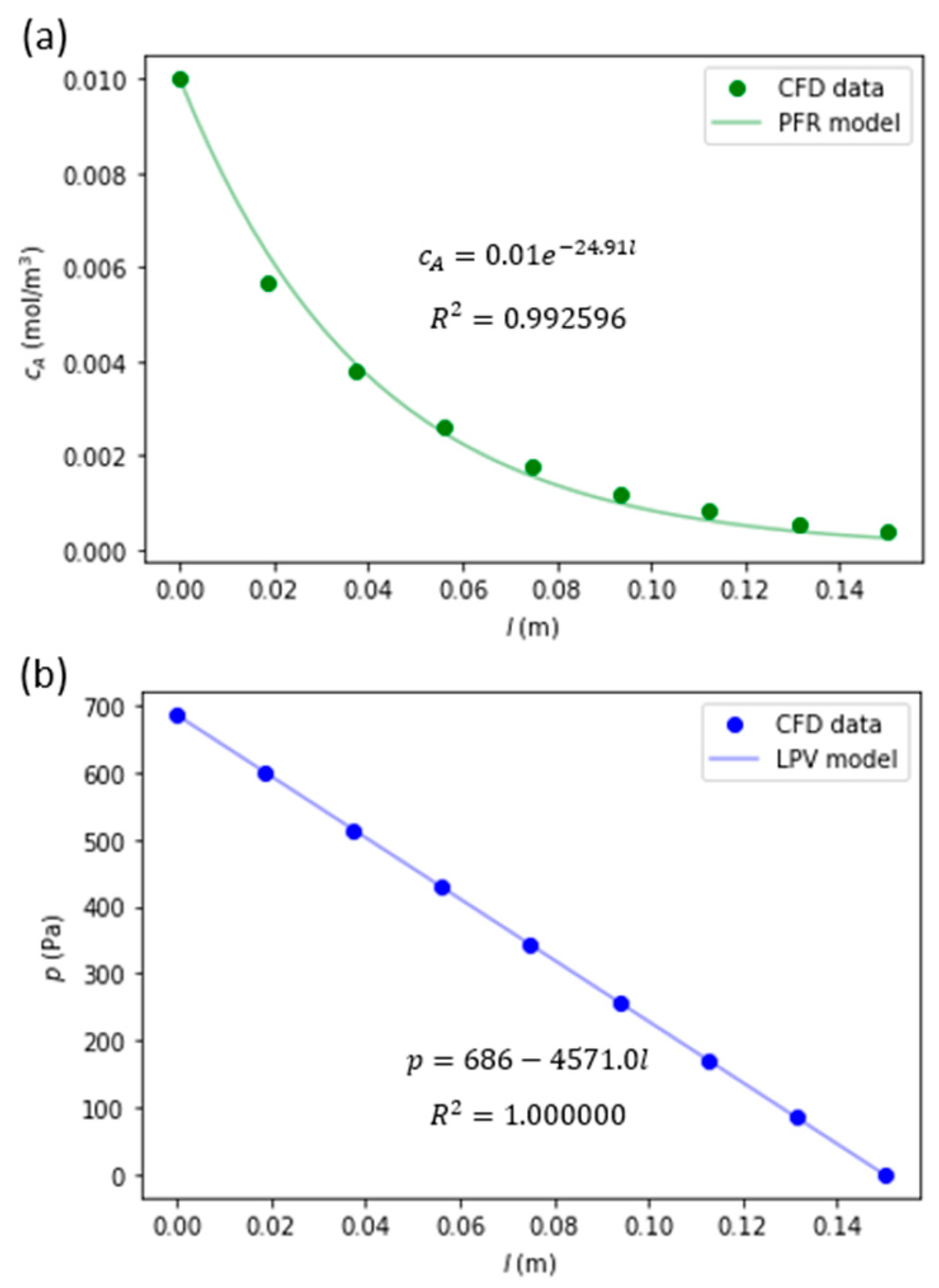
The model order reduction results are also presented in Table A1. The values of the coefficients kc and kp both monotonically decrease as the channel radius increases. The coefficient of determination (R2) values for the PFR model varied from 0.881 to 0.995, and for the LPV model from 0.999997 to 1.0. The R2 values monotonically decreased as the channel radius increased, which could be explained for the PFR model by an increase in departure from the PFR model’s assumptions by an increase in the radial gradients of velocity and species concentrations. Since the algorithm firstly eliminated the geometries with insufficient conversion (with index values from 36 to 109), the MOR models with the smallest values of R2 used in further calculations of optimal channel lengths were 0.991 and 1.0 for the PFR and the LPV models, respectively.
An example of model order reduction fits to radially averaged concentration of species A and pressure is presented in Figure 4.

Figure 4.
Model order reduction fitting results of cA (a) and p (b) for the cylindrical monolith catalyst channel with R = 0.565 and L = 150 mm.
Table 1 contains the channel geometries which enable sufficient conversion of 0.95, and are optimized in length based on the calculated parameters of the PRF model in the MOR stage of the method. The length optimization reduced both the cost and the pressure drops by up to 34.4%, since both the used monolith material volume and the pressure drop are linearly dependent on the channel’s length, originating from Equation (15) and the LPV model, respectively.

Table 1.
The list of the monolith catalysts’ dimensional characteristics, calculated pressure drops, and lengths for achievement of the target conversion of 0.95 with accompanied cost reductions (CR).
After consideration of the maximal allowed pressure drop of 560 Pa, the number of viable geometries reduces to 9 (Table 2). The optimal geometry among the list was selected based on the material cost estimated with Equation (16). The optimal monolith catalyst geometry was the one with index number 27, which had 4700 parallel cylindrical channels with radii of 0.565 mm and lengths of 120.3 mm. Compared to the viable monolith geometry with the highest estimated material cost (index 35), the optimal geometry reduced the material cost by 4.1%.
Table 2.
The list of the monolith catalysts’ dimensional characteristics, calculated pressure drops, lengths, and estimated material cost for achievement of the target conversion of 0.95 and pressure drop below the set limit of 560 Pa with accompanied cost reductions.
If we retrace the optimal monolith geometry with index number 27, we can observe from Table 1 that shortening the length from the initial 150 mm reduced its material cost and pressure drop by 19.8%. The total cost reduction enabled by our monolith dimensioning methodology is hard to predict in real conditions and is dependent on the many factors (e.g., initial/reference catalyst design and geometry) and specific characteristics of the case.
Our estimation is that our methodology would enable chemical engineers to save precious catalyst material of up to 20% and at the same time reduce the operating costs of monolith catalysts via a reduced pressure drop.
4. Conclusions
The presented MOR model was able to successfully reduce the order of the modelling approach with sufficient accuracy and therefore is suitable for modelling small diameter (<2 mm) cylindrical channels, typically used in monolith catalysts. The two-dimensional CFD modelling results from a single cylindrical monolith channel are described using two simple algebraic equations. The first one deals with cross-sectional average of concentration (of species A; modified PFR model) with R2 values ranging from 0.881 to 0.995. The second one (LPV model) models the pressure evolution across the channel’s length, with accuracy related to R2 values equal to or above 0.999997.
Our approach includes the assessment of the washcoat monolith’s material cost with a simple method for assessing the consumption of an active catalyst material which coats the catalyst’s support in a relatively thin (compared to the channel’s dimensions) and uniform manner. The calculated cost of the active catalyst material served us in the selection process within the dimensioning optimization algorithm.
The newly developed computational fluid dynamics, transport, and chemical kinetics-based monolith catalyst dimensioning methodology enables chemical engineers to design and dimension monolith catalysts for many different applications in silico, which enable them to reduce both the material and operation costs while maintaining sufficient catalyst performance and, therefore, achieve its cost-effective performance. According to our results and estimations, the material savings could be in the range of up to 20%.
The presented monolith catalyst dimensioning methodology was conducted in a case of a washcoated monolith catalyst (WMC). However, it could easily be adapted to dimensioning a bulk monolithic catalyst (BMC) with alterations to the estimated material cost equation (Equation (16)).
Our methodology is relatively simple and easy to implement since the user has to know just a few basic initial conditions like space constrains, inflow conditions, the range in the number of catalyst channels, and performance targets, e.g., conversion and pressure drop. From there forward, the only real requirement is having a working computer with sufficient performance characteristics (e.g., computational power, random-access memory (RAM) size), and installed CFD software and some other data processing software which enables the user to virtually test an array of multiple possible monolith catalyst designs and geometries to extract the optimal one for the designated purpose. Therefore, the developed methodology not only reduces the material and operation costs, as already mentioned, but also saves engineers the substantial amount of time and effort required to experimentally test multiple potential catalyst geometries, since only the tests required for validation of the CFD calculations and the tests of the monolith catalyst prototype are necessary.
Author Contributions
Conceptualization, J.V. and A.P.; methodology, J.V. and A.P.; software, J.V.; formal analysis, J.V. and A.P.; investigation, J.V.; data curation, J.V.; writing—original draft, J.V.; writing—review & editing, J.V., A.P. and B.L.; visualization, J.V.; supervision, B.L.; project administration, B.L.; funding acquisition, B.L. All authors have read and agreed to the published version of the manuscript.
Funding
The work was funded by the Slovenian Research and Innovation Agency through core funding P2-0152 and project funding J7-4638.
Data Availability Statement
Data will be available on a reasonable request.
Conflicts of Interest
The authors declare no conflict of interest.
Appendix A. CFD Results and MOR Data Summary
Table A1.
All of the considered monolith catalysts with initial length of 150 mm, their integral dimensional and performance characteristics, Reynolds numbers, and MOR model parameters with corresponding coefficients of determination (R2).
Table A1.
All of the considered monolith catalysts with initial length of 150 mm, their integral dimensional and performance characteristics, Reynolds numbers, and MOR model parameters with corresponding coefficients of determination (R2).
| Index (/) | R (mm) | N (/) | Δp (Pa) | ConA (/) | Re (/) | kc (1/m) | R2 (/) | kp (Pa/m) | R2 (/) |
|---|---|---|---|---|---|---|---|---|---|
| 1 | 0.500 | 6000 | 874 | 0.9812 | 143 | 30.45 | 0.995052 | 5829.2 | 1.000000 |
| 2 | 0.502 | 5950 | 867 | 0.9810 | 144 | 30.19 | 0.995086 | 5780.2 | 1.000000 |
| 3 | 0.504 | 5900 | 860 | 0.9801 | 145 | 30.00 | 0.995251 | 5732.7 | 1.000000 |
| 4 | 0.506 | 5850 | 852 | 0.9793 | 145 | 29.56 | 0.994750 | 5683.9 | 1.000000 |
| 5 | 0.509 | 5800 | 845 | 0.9793 | 146 | 29.55 | 0.994571 | 5635.2 | 1.000000 |
| 6 | 0.511 | 5750 | 838 | 0.9786 | 146 | 29.22 | 0.994666 | 5586.6 | 1.000000 |
| 7 | 0.513 | 5700 | 831 | 0.9776 | 147 | 29.06 | 0.994395 | 5539.0 | 1.000000 |
| 8 | 0.515 | 5650 | 824 | 0.9774 | 148 | 28.79 | 0.994704 | 5490.8 | 1.000000 |
| 9 | 0.518 | 5600 | 816 | 0.9772 | 148 | 28.77 | 0.994608 | 5443.5 | 1.000000 |
| 10 | 0.520 | 5550 | 809 | 0.9764 | 149 | 28.50 | 0.994424 | 5394.4 | 1.000000 |
| 11 | 0.522 | 5500 | 802 | 0.9753 | 150 | 28.21 | 0.994275 | 5345.4 | 1.000000 |
| 12 | 0.525 | 5450 | 794 | 0.9743 | 150 | 27.89 | 0.994155 | 5297.1 | 1.000000 |
| 13 | 0.527 | 5400 | 787 | 0.9737 | 151 | 27.64 | 0.994292 | 5248.7 | 1.000000 |
| 14 | 0.530 | 5350 | 780 | 0.9724 | 152 | 27.41 | 0.993711 | 5199.0 | 1.000000 |
| 15 | 0.532 | 5300 | 773 | 0.9716 | 153 | 27.16 | 0.993869 | 5151.5 | 1.000000 |
| 16 | 0.535 | 5250 | 765 | 0.9704 | 153 | 26.84 | 0.993438 | 5102.4 | 1.000000 |
| 17 | 0.537 | 5200 | 758 | 0.9700 | 154 | 26.73 | 0.993488 | 5053.8 | 1.000000 |
| 18 | 0.540 | 5150 | 751 | 0.9690 | 155 | 26.39 | 0.993145 | 5006.0 | 1.000000 |
| 19 | 0.542 | 5100 | 743 | 0.9682 | 156 | 26.28 | 0.993280 | 4957.4 | 1.000000 |
| 20 | 0.545 | 5050 | 736 | 0.9669 | 156 | 25.90 | 0.993056 | 4908.4 | 1.000000 |
| 21 | 0.548 | 5000 | 729 | 0.9660 | 157 | 25.68 | 0.992873 | 4860.0 | 1.000000 |
| 22 | 0.550 | 4950 | 722 | 0.9654 | 158 | 25.56 | 0.992800 | 4812.1 | 1.000000 |
| 23 | 0.553 | 4900 | 715 | 0.9644 | 159 | 25.32 | 0.992759 | 4764.0 | 1.000000 |
| 24 | 0.556 | 4850 | 707 | 0.9631 | 160 | 25.09 | 0.992401 | 4714.6 | 1.000000 |
| 25 | 0.559 | 4800 | 700 | 0.9626 | 160 | 24.93 | 0.992461 | 4666.9 | 1.000000 |
| 26 | 0.562 | 4750 | 693 | 0.9610 | 161 | 24.56 | 0.991998 | 4618.3 | 1.000000 |
| 27 | 0.565 | 4700 | 686 | 0.9622 | 162 | 24.91 | 0.992596 | 4571.0 | 1.000000 |
| 28 | 0.568 | 4650 | 678 | 0.9612 | 163 | 24.68 | 0.992391 | 4523.2 | 1.000000 |
| 29 | 0.571 | 4600 | 671 | 0.9604 | 164 | 24.55 | 0.992352 | 4475.5 | 1.000000 |
| 30 | 0.574 | 4550 | 664 | 0.9596 | 165 | 24.30 | 0.992217 | 4426.9 | 1.000000 |
| 31 | 0.577 | 4500 | 657 | 0.9583 | 166 | 24.08 | 0.992139 | 4378.2 | 1.000000 |
| 32 | 0.581 | 4450 | 649 | 0.9563 | 167 | 23.72 | 0.991320 | 4329.4 | 1.000000 |
| 33 | 0.584 | 4400 | 642 | 0.9550 | 167 | 23.49 | 0.991487 | 4280.6 | 1.000000 |
| 34 | 0.587 | 4350 | 635 | 0.9524 | 168 | 23.15 | 0.991095 | 4232.2 | 1.000000 |
| 35 | 0.591 | 4300 | 627 | 0.9513 | 169 | 22.86 | 0.990751 | 4183.1 | 1.000000 |
| 36 | 0.594 | 4250 | 620 | 0.9495 | 170 | 22.72 | 0.990327 | 4133.9 | 1.000000 |
| 37 | 0.598 | 4200 | 613 | 0.9472 | 171 | 22.30 | 0.989910 | 4084.7 | 1.000000 |
| 38 | 0.601 | 4150 | 605 | 0.9454 | 172 | 22.04 | 0.989998 | 4036.0 | 1.000000 |
| 39 | 0.605 | 4100 | 598 | 0.9438 | 173 | 21.87 | 0.989740 | 3987.0 | 1.000000 |
| 40 | 0.609 | 4050 | 591 | 0.9411 | 175 | 21.49 | 0.989604 | 3938.0 | 1.000000 |
| 41 | 0.612 | 4000 | 583 | 0.9374 | 176 | 20.96 | 0.989082 | 3888.7 | 1.000000 |
| 42 | 0.616 | 3950 | 576 | 0.9341 | 177 | 20.62 | 0.988426 | 3839.5 | 1.000000 |
| 43 | 0.620 | 3900 | 568 | 0.9303 | 178 | 20.24 | 0.987491 | 3790.2 | 1.000000 |
| 44 | 0.624 | 3850 | 561 | 0.9279 | 179 | 19.93 | 0.987649 | 3741.2 | 1.000000 |
| 45 | 0.628 | 3800 | 554 | 0.9245 | 180 | 19.59 | 0.987004 | 3691.9 | 1.000000 |
| 46 | 0.632 | 3750 | 546 | 0.9223 | 181 | 19.37 | 0.986508 | 3643.1 | 1.000000 |
| 47 | 0.637 | 3700 | 539 | 0.9205 | 183 | 19.15 | 0.986923 | 3595.3 | 1.000000 |
| 48 | 0.641 | 3650 | 532 | 0.9178 | 184 | 18.94 | 0.986445 | 3546.3 | 1.000000 |
| 49 | 0.645 | 3600 | 525 | 0.9155 | 185 | 18.71 | 0.986071 | 3497.8 | 0.999999 |
| 50 | 0.650 | 3550 | 517 | 0.9126 | 186 | 18.44 | 0.985406 | 3449.2 | 0.999999 |
| 51 | 0.655 | 3500 | 510 | 0.9100 | 188 | 18.21 | 0.985677 | 3400.8 | 0.999999 |
| 52 | 0.659 | 3450 | 503 | 0.9072 | 189 | 17.96 | 0.984682 | 3352.3 | 0.999999 |
| 53 | 0.664 | 3400 | 496 | 0.9048 | 190 | 17.79 | 0.984604 | 3304.4 | 1.000000 |
| 54 | 0.669 | 3350 | 488 | 0.9025 | 192 | 17.58 | 0.984443 | 3255.7 | 0.999999 |
| 55 | 0.674 | 3300 | 481 | 0.9002 | 193 | 17.40 | 0.984127 | 3207.8 | 0.999999 |
| 56 | 0.679 | 3250 | 474 | 0.8975 | 195 | 17.19 | 0.983736 | 3159.5 | 0.999999 |
| 57 | 0.685 | 3200 | 467 | 0.8938 | 196 | 16.93 | 0.983234 | 3110.9 | 0.999999 |
| 58 | 0.690 | 3150 | 459 | 0.8924 | 198 | 16.86 | 0.983105 | 3062.5 | 0.999999 |
| 59 | 0.696 | 3100 | 452 | 0.8877 | 200 | 16.51 | 0.982191 | 3013.9 | 0.999999 |
| 60 | 0.701 | 3050 | 445 | 0.8867 | 201 | 16.43 | 0.982221 | 2966.3 | 0.999999 |
| 61 | 0.707 | 3000 | 438 | 0.8839 | 203 | 16.25 | 0.982359 | 2917.7 | 0.999999 |
| 62 | 0.713 | 2950 | 430 | 0.8817 | 205 | 16.10 | 0.982212 | 2869.0 | 0.999999 |
| 63 | 0.719 | 2900 | 423 | 0.8779 | 206 | 15.85 | 0.981770 | 2820.5 | 0.999999 |
| 64 | 0.725 | 2850 | 416 | 0.8735 | 208 | 15.61 | 0.980241 | 2772.4 | 1.000000 |
| 65 | 0.732 | 2800 | 409 | 0.8699 | 210 | 15.36 | 0.980929 | 2724.0 | 0.999999 |
| 66 | 0.739 | 2750 | 401 | 0.8657 | 212 | 15.12 | 0.980276 | 2675.0 | 0.999999 |
| 67 | 0.745 | 2700 | 394 | 0.8571 | 214 | 14.69 | 0.978628 | 2625.7 | 0.999999 |
| 68 | 0.752 | 2650 | 387 | 0.8510 | 216 | 14.33 | 0.977858 | 2577.2 | 1.000000 |
| 69 | 0.760 | 2600 | 379 | 0.8451 | 218 | 14.08 | 0.977024 | 2528.3 | 0.999999 |
| 70 | 0.767 | 2550 | 372 | 0.8385 | 220 | 13.75 | 0.975798 | 2479.5 | 0.999999 |
| 71 | 0.775 | 2500 | 365 | 0.8335 | 222 | 13.53 | 0.974831 | 2430.5 | 0.999999 |
| 72 | 0.782 | 2450 | 357 | 0.8269 | 224 | 13.25 | 0.973394 | 2381.7 | 0.999999 |
| 73 | 0.791 | 2400 | 350 | 0.8208 | 227 | 13.05 | 0.971437 | 2333.0 | 0.999999 |
| 74 | 0.799 | 2350 | 343 | 0.8157 | 229 | 12.81 | 0.971131 | 2284.5 | 0.999999 |
| 75 | 0.808 | 2300 | 335 | 0.8087 | 232 | 12.51 | 0.970381 | 2235.8 | 0.999999 |
| 76 | 0.816 | 2250 | 328 | 0.8049 | 234 | 12.40 | 0.969208 | 2187.7 | 0.999999 |
| 77 | 0.826 | 2200 | 321 | 0.8007 | 237 | 12.21 | 0.968941 | 2139.1 | 0.999999 |
| 78 | 0.835 | 2150 | 314 | 0.7953 | 240 | 12.00 | 0.968407 | 2090.7 | 0.999999 |
| 79 | 0.845 | 2100 | 306 | 0.7879 | 242 | 11.76 | 0.966999 | 2042.4 | 0.999999 |
| 80 | 0.855 | 2050 | 299 | 0.7808 | 245 | 11.51 | 0.965259 | 1993.6 | 0.999999 |
| 81 | 0.866 | 2000 | 292 | 0.7752 | 248 | 11.31 | 0.964688 | 1945.2 | 0.999999 |
| 82 | 0.877 | 1950 | 285 | 0.7711 | 252 | 11.17 | 0.964817 | 1897.3 | 0.999999 |
| 83 | 0.889 | 1900 | 277 | 0.7634 | 255 | 10.93 | 0.962795 | 1848.8 | 0.999999 |
| 84 | 0.900 | 1850 | 270 | 0.7580 | 258 | 10.76 | 0.962640 | 1800.3 | 0.999999 |
| 85 | 0.913 | 1800 | 263 | 0.7501 | 262 | 10.51 | 0.961581 | 1751.9 | 0.999999 |
| 86 | 0.926 | 1750 | 255 | 0.7418 | 266 | 10.27 | 0.959729 | 1703.3 | 0.999999 |
| 87 | 0.939 | 1700 | 248 | 0.7319 | 269 | 9.99 | 0.957383 | 1653.9 | 0.999999 |
| 88 | 0.953 | 1650 | 241 | 0.7226 | 273 | 9.76 | 0.955118 | 1605.0 | 0.999999 |
| 89 | 0.968 | 1600 | 233 | 0.7067 | 278 | 9.33 | 0.951942 | 1555.5 | 0.999999 |
| 90 | 0.984 | 1550 | 226 | 0.6929 | 282 | 8.97 | 0.948455 | 1506.5 | 0.999999 |
| 91 | 1.000 | 1500 | 219 | 0.6860 | 287 | 8.83 | 0.947314 | 1458.2 | 0.999999 |
| 92 | 1.017 | 1450 | 211 | 0.6813 | 292 | 8.74 | 0.945683 | 1410.2 | 0.999999 |
| 93 | 1.035 | 1400 | 204 | 0.6692 | 297 | 8.45 | 0.944485 | 1361.6 | 0.999998 |
| 94 | 1.054 | 1350 | 197 | 0.6626 | 302 | 8.28 | 0.943402 | 1313.4 | 0.999998 |
| 95 | 1.074 | 1300 | 190 | 0.6525 | 308 | 8.07 | 0.941091 | 1264.9 | 0.999998 |
| 96 | 1.095 | 1250 | 182 | 0.6434 | 314 | 7.89 | 0.939183 | 1216.4 | 0.999998 |
| 97 | 1.118 | 1200 | 175 | 0.6324 | 321 | 7.67 | 0.937808 | 1167.3 | 0.999998 |
| 98 | 1.142 | 1150 | 168 | 0.6167 | 328 | 7.35 | 0.932660 | 1118.6 | 0.999998 |
| 99 | 1.168 | 1100 | 160 | 0.5970 | 335 | 6.99 | 0.925107 | 1069.3 | 0.999998 |
| 100 | 1.195 | 1050 | 153 | 0.5843 | 343 | 6.75 | 0.922493 | 1020.7 | 0.999998 |
| 101 | 1.225 | 1000 | 146 | 0.5735 | 351 | 6.56 | 0.919182 | 972.5 | 0.999998 |
| 102 | 1.257 | 950 | 139 | 0.5609 | 360 | 6.35 | 0.914481 | 923.9 | 0.999998 |
| 103 | 1.291 | 900 | 131 | 0.5490 | 370 | 6.15 | 0.912582 | 875.5 | 0.999998 |
| 104 | 1.328 | 850 | 124 | 0.5355 | 381 | 5.92 | 0.909780 | 826.9 | 0.999998 |
| 105 | 1.369 | 800 | 117 | 0.5161 | 393 | 5.62 | 0.901627 | 777.7 | 0.999997 |
| 106 | 1.414 | 750 | 109 | 0.4981 | 406 | 5.35 | 0.893601 | 728.8 | 0.999997 |
| 107 | 1.464 | 700 | 102 | 0.4856 | 420 | 5.16 | 0.890363 | 680.4 | 0.999997 |
| 108 | 1.519 | 650 | 95 | 0.4707 | 436 | 4.94 | 0.888446 | 632.1 | 0.999997 |
| 109 | 1.581 | 600 | 88 | 0.4540 | 453 | 4.70 | 0.880629 | 583.6 | 0.999997 |
The bold values relate to the optimal monolith catalyst geometry.
References
- Cybulski, A.; Moulijn, J.A. Monoliths in Heterogeneous Catalysis. Catal. Rev.—Sci. Eng. 1994, 36, 179–270. [Google Scholar] [CrossRef]
- Roy, S.; Bauer, T.; Al-Dahhan, M.; Lehner, P.; Turek, T. Monoliths as Multiphase Reactors: A Review. AIChE J. 2004, 50, 2918–2938. [Google Scholar] [CrossRef]
- Boger, T.; Heibel, A.K.; Sorensen, C.M. Monolithic Catalysts for the Chemical Industry. Ind. Eng. Chem. Res. 2004, 43, 4602–4611. [Google Scholar] [CrossRef]
- Gokalp, B. Using the Three-Way Catalyst Monolith Reactor for Reducing Exhaust Emissions. J. Renew. Sustain. Energy 2012, 4, 43114. [Google Scholar] [CrossRef]
- Nandi, S.; Arango, P.; Chaillou, C.; Dujardin, C.; Granger, P.; Laigle, E.; Nicolle, A.; Norsic, C.; Richard, M. Relationship between Design Strategies of Commercial Three-Way Monolithic Catalysts and Their Performances in Realistic Conditions. Catal. Today 2022, 384, 122–132. [Google Scholar] [CrossRef]
- Rico-Pérez, V.; García-Cortés, J.M.; De Lecea, C.S.-M.; Bueno-López, A. NOx Reduction to N2 with Commercial Fuel in a Real Diesel Engine Exhaust Using a Dual Bed of Pt/Beta Zeolite and RhOx/Ceria Monolith Catalysts. Chem. Eng. Sci. 2013, 104, 557–564. [Google Scholar] [CrossRef]
- Dupont, V.; Moallemi, F.; Williams, A.; Zhang, S. Combustion of Methane in Catalytic Honeycomb Monolith Burners. Int. J. Energy Res. 2000, 24, 1181–1201. [Google Scholar] [CrossRef]
- Tacchino, S.; Vella, L.D.; Specchia, S. Catalytic Combustion of CH4 and H2 into Micro-Monoliths. Catal. Today 2010, 157, 440–445. [Google Scholar] [CrossRef]
- Chao, Y.-C.; Chen, G.-B.; Hsu, H.-W.; Hsu, J.-R. Catalytic Combustion of Gasified Biomass in a Platinum Monolith Honeycomb Reactor. Appl. Catal. A Gen. 2004, 261, 99–107. [Google Scholar] [CrossRef]
- Wu, P.; Li, X.; Ji, S.; Lang, B.; Habimana, F.; Li, C. Steam Reforming of Methane to Hydrogen over Ni-Based Metal Monolith Catalysts. Catal. Today 2009, 146, 82–86. [Google Scholar] [CrossRef]
- Roh, H.-S.; Lee, D.K.; Koo, K.Y.; Jung, U.H.; Yoon, W.L. Natural Gas Steam Reforming for Hydrogen Production over Metal Monolith Catalyst with Efficient Heat-Transfer. Int. J. Hydrogen Energy 2010, 35, 1613–1619. [Google Scholar] [CrossRef]
- Moraes, T.S.; Borges, L.E.P.; Farrauto, R.; Noronha, F.B. Steam Reforming of Ethanol on Rh/SiCeO2 Washcoated Monolith Catalyst: Stable Catalyst Performance. Int. J. Hydrogen Energy 2018, 43, 115–126. [Google Scholar] [CrossRef]
- Bustinza, A.; Frías, M.; Liu, Y.; García-Bordejé, E. Mono-and Bimetallic Metal Catalysts Based on Ni and Ru Supported on Alumina-Coated Monoliths for CO2 Methanation. Catal. Sci. Technol. 2020, 10, 4061–4071. [Google Scholar] [CrossRef]
- García-Moncada, N.; Navarro, J.C.; Odriozola, J.A.; Lefferts, L.; Faria, J.A. Enhanced Catalytic Activity and Stability of Nanoshaped Ni/CeO2 for CO2 Methanation in Micro-Monoliths. Catal. Today 2022, 383, 205–215. [Google Scholar] [CrossRef]
- El Sawi, M.; Frusteri, F.; Parmaliana, A.; Formisano, B.; Giordano, N. A Kinetic Study of Cyclohexane Dehydrogenation on Pt Monolithic Catalyst. J. Chem. Technol. Biotechnol. 1986, 36, 122–128. [Google Scholar] [CrossRef]
- Parmaliana, A.; Crisafulli, C.; Maggiore, R.; Bart, J.C.J.; Giordano, N. Catalytic Activity of Honeycomb Catalysts, I. The Benzene-Cyclohexane (de) Hydrogenation Reaction. React. Kinet. Catal. Lett. 1981, 18, 295–299. [Google Scholar] [CrossRef]
- Tronconi, E.; Cavanna, A.; Orsenigo, C.; Forzatti, P. Transient Kinetics of SO2 Oxidation over SCR-DeNO X Monolith Catalysts. Ind. Eng. Chem. Res. 1999, 38, 2593–2598. [Google Scholar] [CrossRef]
- Subbanna, P.; Greene, H.; Desai, F. Catalytic Oxidation of Polychlorinated Biphenyls in a Monolithic Reactor System. Environ. Sci. Technol. 1988, 22, 557–561. [Google Scholar] [CrossRef]
- Michael, B.C.; Nare, D.N.; Schmidt, L.D. Catalytic Partial Oxidation of Ethane to Ethylene and Syngas over Rh and Pt Coated Monoliths: Spatial Profiles of Temperature and Composition. Chem. Eng. Sci. 2010, 65, 3893–3902. [Google Scholar] [CrossRef]
- Portela, R.; Wolf, P.; Marinkovic, J.M.; Serrano-Lotina, A.; Riisager, A.; Haumann, M. Tailored Monolith Supports for Improved Ultra-Low Temperature Water-Gas Shift Reaction. React. Chem. Eng. 2021, 6, 2114–2124. [Google Scholar] [CrossRef]
- Quiney, A.S.; Germani, G.; Schuurman, Y. Optimization of a Water–Gas Shift Reactor over a Pt/Ceria/Alumina Monolith. J. Power Sources 2006, 160, 1163–1169. [Google Scholar] [CrossRef]
- Liu, H.; Zhao, J.; Li, C.; Ji, S. Conceptual Design and CFD Simulation of a Novel Metal-Based Monolith Reactor with Enhanced Mass Transfer. Catal. Today 2005, 105, 401–406. [Google Scholar] [CrossRef]
- Di Benedetto, A.; Di Sarli, V. CFD Modeling and Simulation of a Catalytic Micro-Monolith. Int. J. Chem. React. Eng. 2011, 9, e2526. [Google Scholar] [CrossRef]
- Shin, S.B.; Skau, K.I.; Menon, M.; Maroor, S.; Spatenka, S. A Modelling Approach to Kinetics Study and Novel Monolith Channel Design for Selective Catalytic Reduction (SCR) Applications. Chem. Eng. Res. Des. 2019, 142, 412–428. [Google Scholar] [CrossRef]
- Shaikh, S.K.; Pathan, K.A.; Chaudhary, Z.I.; Khan, S.A. CFD Analysis of an Automobile Catalytic Converter to Obtain Flow Uniformity and to Minimize Pressure Drop across the Monolith. CFD Lett. 2020, 12, 116–128. [Google Scholar] [CrossRef]
- Sandu, V.-C.; Cormos, A.-M.; Dumbrava, I.-D.; Imre-Lucaci, A.; Cormos, C.-C.; de Boer, R.; Boon, J.; Sluijter, S. Assessment of CO2 Capture Efficiency in Packed Bed versus 3D-Printed Monolith Reactors for SEWGS Using CFD Modeling. Int. J. Greenh. Gas Control 2021, 111, 103447. [Google Scholar] [CrossRef]
- Sadeghi, F.; Tirandazi, B.; Khalili-Garakani, A.; Nasseri, S.; Nodehi, R.N.; Mostoufi, N. Investigating the Effect of Channel Geometry on Selective Catalytic Reduction of NOx in Monolith Reactors. Chem. Eng. Res. Des. 2017, 118, 21–30. [Google Scholar] [CrossRef]
- Štěpánek, J.; Kočí, P.; Marek, M.; Kubíček, M. Catalyst Simulations Based on Coupling of 3D CFD Tool with Effective 1D Channel Models. Catal. Today 2012, 188, 87–93. [Google Scholar] [CrossRef]
- Chen, J.; Yang, H.; Wang, N.; Ring, Z.; Dabros, T. Mathematical Modeling of Monolith Catalysts and Reactors for Gas Phase Reactions. Appl. Catal. A Gen. 2008, 345, 1–11. [Google Scholar] [CrossRef]
- Ratnakar, R.R.; Bhattacharya, M.; Balakotaiah, V. Reduced Order Models for Describing Dispersion and Reaction in Monoliths. Chem. Eng. Sci. 2012, 83, 77–92. [Google Scholar] [CrossRef]
- Nien, T.; Mmbaga, J.P.; Hayes, R.E.; Votsmeier, M. Hierarchical Multi-Scale Model Reduction in the Simulation of Catalytic Converters. Chem. Eng. Sci. 2013, 93, 362–375. [Google Scholar] [CrossRef]
- Tu, M.; Ratnakar, R.; Balakotaiah, V. Reduced Order Models with Local Property Dependent Transfer Coefficients for Real Time Simulations of Monolith Reactors. Chem. Eng. J. 2020, 383, 123074. [Google Scholar] [CrossRef]
- Pérez-Cadenas, A.F.; Kapteijn, F.; Moulijn, J.A.; Maldonado-Hódar, F.J.; Carrasco-Marín, F.; Moreno-Castilla, C. Pd and Pt Catalysts Supported on Carbon-Coated Monoliths for Low-Temperature Combustion of Xylenes. Carbon 2006, 44, 2463–2468. [Google Scholar] [CrossRef]
- Consentino, L.; Pantaleo, G.; Parola, V.L.; Migliore, C.; Greca, E.L.; Liotta, L.F. NH3-NO SCR Catalysts for Engine Exhaust Gases Abatement: Replacement of Toxic V2O5 with MnOx to Improve the Environmental Sustainability. Top. Catal. 2023, 66, 850–859. [Google Scholar] [CrossRef]
- Ferella, F. A Review on Management and Recycling of Spent Selective Catalytic Reduction Catalysts. J. Clean. Prod. 2020, 246, 118990. [Google Scholar] [CrossRef]
- Metkar, P.S.; Harold, M.P.; Balakotaiah, V. Experimental and Kinetic Modeling Study of NH3-SCR of NOx on Fe-ZSM-5, Cu-Chabazite and Combined Fe- and Cu-Zeolite Monolithic Catalysts. Chem. Eng. Sci. 2013, 87, 51–66. [Google Scholar] [CrossRef]
- Colombo, M.; Nova, I.; Tronconi, E. Detailed Kinetic Modeling of the NH3–NO/NO2 SCR Reactions over a Commercial Cu-Zeolite Catalyst for Diesel Exhausts after Treatment. Catal. Today 2012, 197, 243–255. [Google Scholar] [CrossRef]
- Benjamin, S.F.; Liu, Z.; Roberts, C.A. Automotive Catalyst Design for Uniform Conversion Efficiency. Appl. Math. Model. 2004, 28, 559–572. [Google Scholar] [CrossRef]
- Baharudin, L.; Watson, M.J. Monolithic Substrate Support Catalyst Design Considerations for Steam Methane Reforming Operation. Rev. Chem. Eng. 2018, 34, 481–501. [Google Scholar] [CrossRef]
- Chang, H.-C.; Wang, L.-C. A Simple Proof of Thue’s Theorem on Circle Packing. arXiv 2010, arXiv:1009.4322. [Google Scholar]
- Tomašić, V. Application of the Monoliths in DeNOx Catalysis. Catal. Today 2007, 119, 106–113. [Google Scholar] [CrossRef]
- Comsol. CFD Module User’s Guide; Version 5.4; Comsol AB: Stockholm, Sweden, 2018; Available online: https://doc.comsol.com/5.4/doc/com.comsol.help.cfd/CFDModuleUsersGuide.pdf (accessed on 28 October 2023).
- Comsol. Chemical Reaction Engineering Module User’s Guide; Version 5.4; Comsol AB: Stockholm, Sweden, 2018; Available online: https://doc.comsol.com/5.4/doc/com.comsol.help.chem/ChemicalReactionEngineeringModuleUsersGuide.pdf (accessed on 28 October 2023).
- Krocher, O.; Elsener, M. Combination of V2O5/WO3− TiO2, Fe− ZSM5, and Cu− ZSM5 Catalysts for the Selective Catalytic Reduction of Nitric Oxide with Ammonia. Ind. Eng. Chem. Res. 2008, 47, 8588–8593. [Google Scholar] [CrossRef]
- Wilke, C.R. A Viscosity Equation for Gas Mixtures. J. Chem. Phys. 1950, 18, 517–519. [Google Scholar] [CrossRef]
- Voglar, J.; Teržan, J.; Kroflič, A.; Huš, M.; Likozar, B. Mechanistic Modelling of Catalytic NOX Reduction Reactions after Hydrogen or Ammonia Combustion on Multiple Scales. Renew. Sustain. Energy Rev. 2023, 186, 113666. [Google Scholar] [CrossRef]
- Cussler, E.L. Diffusion: Mass Transfer in Fluid Systems; Cambridge University Press: Cambridge, UK, 2009; ISBN 0521871212. [Google Scholar]
- Liu, Z.; Yi, Y.; Zhang, S.; Zhu, T.; Zhu, J.; Wang, J. Selective Catalytic Reduction of NOx with NH3 over Mn-Ce Mixed Oxide Catalyst at Low Temperatures. Catal. Today 2013, 216, 76–81. [Google Scholar] [CrossRef]
- Wang, Z.; Lan, J.; Haneda, M.; Liu, Z. Selective Catalytic Reduction of NOx with NH3 over a Novel Co-Ce-Ti Catalyst. Catal. Today 2021, 376, 222–228. [Google Scholar] [CrossRef]
- Gonzo, E.E. Hydrogen from Methanol-Steam Reforming. Isothermal and Adiabatic Monolith Reactors’ Simulation. Int. J. Hydrogen Energy 2008, 33, 3511–3516. [Google Scholar] [CrossRef]
- Heiredal, M.L.; Jensen, A.D.; Thøgersen, J.R.; Frandsen, F.J.; Friemann, J. Pilot-scale Investigation and CFD Modeling of Particle Deposition in Low-dust Monolithic SCR DeNOx Catalysts. AIChE J. 2013, 59, 1919–1933. [Google Scholar] [CrossRef]
- Cutler, A.H.; Antal Jr, M.J.; Jones Jr, M. A Critical Evaluation of the Plug-Flow Idealization of Tubular-Flow Reactor Data. Ind. Eng. Chem. Res. 1988, 27, 691–697. [Google Scholar] [CrossRef]
- Moody, L.F. Friction Factors for Pipe Flow. Trans. Am. Soc. Mech. Eng. 1944, 66, 671–678. [Google Scholar] [CrossRef]
- Gekas, I.; Vressner, A.; Johansen, K. NOx Reduction Potential of V-SCR Catalyst in SCR/DOC/DPF Configuration Targeting Euro VI Limits from High Engine NOx Levels; SAE Technical Paper 2009-01-0626; SAE International: Warrendale, PA, USA, 2009. [Google Scholar]
- Cornejo, I.; Nikrityuk, P.; Hayes, R.E. The Influence of Channel Geometry on the Pressure Drop in Automotive Catalytic Converters: Model Development and Validation. Chem. Eng. Sci. 2020, 212, 115317. [Google Scholar] [CrossRef]
- Lin, K.-S.; Mdlovu, N.V.; Juang, R.-S.; Tang, M.-T. Fine Structural Characterization of Noble Metals in Washcoat of Motorcycle Three-Way Converter Catalysts. J. Environ. Chem. Eng. 2023, 11, 109530. [Google Scholar] [CrossRef]

Disclaimer/Publisher’s Note: The statements, opinions and data contained in all publications are solely those of the individual author(s) and contributor(s) and not of MDPI and/or the editor(s). MDPI and/or the editor(s) disclaim responsibility for any injury to people or property resulting from any ideas, methods, instructions or products referred to in the content. |
© 2024 by the authors. Licensee MDPI, Basel, Switzerland. This article is an open access article distributed under the terms and conditions of the Creative Commons Attribution (CC BY) license (https://creativecommons.org/licenses/by/4.0/).