Article

Dependence of Pressure Characteristics of Pressurized Pulse Water Jet Chamber on Nozzle Diameter

1
Anhui Institute of Information Technology, Wuhu 241000, China
2
State Key Laboratory of Tunnel Boring Machine and Intelligent Operations, Zhengzhou 450001, China
3
China Railway Tunnel Group Co., Ltd., Guangzhou 511458, China
*
Author to whom correspondence should be addressed.
Processes 2024, 12(8), 1708; https://doi.org/10.3390/pr12081708
Submission received: 25 June 2024 / Revised: 31 July 2024 / Accepted: 2 August 2024 / Published: 14 August 2024

Abstract

:
The nozzle is the key element of the water jet generator for energy conversion. In order to explore the influence of the nozzle diameter on the pressure characteristics of the supercharged pulsed water jet plenum chamber, a supercharged pulsed water jet pressure acquisition system was established, and the equations of motion and theoretical pressurization ratio equations of the supercharged pulsed water jet generator were established. The pressurization chamber pressure acquisition experiments under different nozzle diameters were carried out. The research results show that the pressurized pulsed water jet generator has a critical nozzle diameter of 0.6 mm. When the nozzle diameter is less than the critical diameter, the pressure in the boost chamber is equal to the product of the driving pressure and the boost ratio. As the nozzle changes, there is no significant change in the peak pressure and frequency of the boost chamber. When the nozzle diameter is greater than the critical diameter, there is a non-linear relationship between the boost chamber pressure and the driving pressure. As the nozzle diameter gradually increases, the actual boost ratio gradually decreases, and the peak pressure of the boost chamber further decreases. The nozzle diameter can no longer provide a load for the establishment of fluid pressure in the boost chamber. The results of this research provide a research basis for further controlling the pressure characteristics of the boost pulse water jet.

1. Introduction

With the steady advancement of China’s major national strategies, such as “Western Development” and the “150 Major Water Conservancy Projects”, major projects such as the Sichuan–Xizang Railway and the Plateau Water Diversion have started construction, and the application field of full-face hard rock tunnel boring machines (TBMs) has been further promoted [1]. Due to its ultra-high compressive strength and high abrasive characteristics in wear-resistant hard rock formations [2], TBM hob penetration is blocked [3], and there is severe wear [4] and frequent tool changes [5], which restrict the on-site efficiency and low-cost construction speed [6].
Conventional hob strengthening [7,8], tool layout optimization [9], and TBM main driving thrust enhancement cannot effectively solve the rock-breaking problem of extremely hard rock formation boring machines. External energy must be introduced to cooperate with mechanical cutters to break the rock mass [10,11,12]. As a special rock-breaking technology [13,14,15], water jet technology has an excellent independent rock-breaking ability [16] and can be coupled with TBM cutters to break hard rock [17,18]. Water jet cuts into slits or volume damage reduce the rock-breaking resistance of the cutters [19,20] and improve the penetration ability of normal cracks [21]. Among them, the pressurized pulsed water jet, as a new type of pulsed water jet [22], has the equipment characteristics of low pressure input–double pressure pulse output–efficient breaking of hard rock [23]. It can generate multiple pulses [24] and impact hard-rock breaking. The effect is significant [25] and is expected to develop into a new generation of the TBM collaborative rock-breaking method [26]. The pressure characteristics of the pressurized pulsed water jet plenum directly affect its rock-breaking ability, and are jointly influenced by the structural characteristics, driving parameters, and nozzle parameters of the jet generator. The nozzle, as an important transducer for the transformation of fluid from static characteristics to a dynamic jet, is a key influencing parameter on the pressure characteristics of the jet plenum. However, the mechanism of the influence of the nozzle on the pressure characteristics in the pressurized chamber of the pressurized pulsed water jet is unclear.
Jiwei Wen et al. [27] comprehensively used a vertical experimental design, a computational fluid dynamics numerical simulation, a theoretical calculation, a water jet impact force test, and an artificial sandstone crushing experiment to obtain the best structural parameters of the straight cone nozzle. Dhruv Apte et al. [28] used various turbulence models to simulate the cavitation flow in Venturi nozzles, and analyzed the flow dynamics and turbulence characteristics, and compared them with the experimental data. Daotong Chong et al. [29] theoretically and experimentally studied the effect of the nozzle structure on the injection length of submerged condensed steam in still water. LuYun Huang et al. [30] conducted a 3D simulation of the hydrodynamic performance of the nozzle based on the operating characteristics of the ultra-high pressure water jet rust nozzle, considering the cavitation effect, the multiphase flow, and the liquid compressibility models. Makhsuda Juraeva et al. [31] proposed a calculation method for designing and optimizing water spray nozzles using experimental design methods. C. Palani Kumar et al. [32] studied the kinetics of water jets occurring on the needle tip. Deng Li et al. [33,34] analyzed the effect of the nozzle inlet area discontinuity based on previous related research, and then conducted experimental studies on axial pressure oscillations. Chengting Liu et al. [35] conducted experimental studies on the working conditions of the nozzles under different flow rates, and analyzed them from four aspects: cavitation shape, pressure pulse frequency, velocity fluctuation amplitude, and erosion effect. Andrea Marcon et al. [36] investigated the scalability of the peening process by comparing co-flow nozzles with an increased size but with the same diameter ratio. Piush Raj et al. [37] compared sandstone erosion caused by continuous water jets and pulsed water jets at frequencies of f = 20 GHz and 40 GHz. Z. Riha et al. [38] studied the erosion phenomena of a high-speed modulated water jet (MWJ) and a continuous water jet (CWJ) during the interaction between the spray and the material. Xianzhi Song et al. [39] established a porous nozzle model to study the characteristics of multiple hydrothermal jet flow fields and heat transfer to the surrounding rocks. The instantaneous impingement flow field with multiple hydrothermal jets was analyzed from the perspective of the axial temperature, the bottomhole temperature, and the bottomhole pressure. Gittiphong Sripanagul et al. [40] experimentally studied the performance of high-speed water jets generated by electromagnetic actuators to drill holes on stone surfaces. Madhulika Srivastava et al. [41] studied the interaction of the distance behind the erosion trajectory of the water jet and the lateral velocity of the nozzle on the erosion depth. Rupam Tripathi et al. [42] compared the erosion properties of the continuous and ultrasonic pulsed water jet techniques on granite samples at three pressure levels of 20 MPa, 40 MPa, and 60 MPa. Zu’an Wang et al. [43] experimentally studied the effect of the modulation position on the impact performance (axial impact pressure, erosion radius, and erosion depth) of the mechanically modulated pulsed water jet (MPWJ). Yan Xu et al. [44] analyzed the influence of nozzle geometry on the structure of the cavitation clouds. Michal Zelenak et al. [45] studied the effect of water pressure on the shape, velocity field, and frequency of self-excited jets.
To sum up, some of the abovementioned scholars have discussed the relationship between different types of water jet pressure and the nozzle diameter from different angles, and some scholars have analyzed the relationship between the supercharger pressure and the nozzle diameter. However, the relationship between the pressure characteristics in the pressurized pulse water jet pressurization chamber and the nozzle diameter is unclear. Therefore, the author and his team took the independently developed pressurized pulsed water jet generator as the core, collected the pressure of the pressurized pulsed water jet plenum, and built a pressurized pulsed water jet plenum model, in order to jointly explore the internal relationship between the pressure characteristics of the pressurized water jet plenum and the nozzle diameter through experimental and theoretical research.

2. Pressure Boosting Theory of a Pressurized Pulse Water Jet Generator

2.1. Equations of Motion of the Generator

In order to achieve an ultra-high pressure pulse output of a low-pressure driving fluid in the engineering sites, the author’s team proposes to use fluid pressurization technology and hydraulic self-commutation to achieve self-commutation and periodic pressurization of the fluid, thereby achieving pressure doubling and the intermittent injection of the fluid, which is a pressurized pulse water jet generation device. The conversion of a low pressure and large flow continuous fluid to a high pressure (ultra-high pressure) and small flow pulsed fluid through a pressurized pulsed water jet generator.
The structure and physical diagram of the pressurized pulse water jet generator device are shown in Figure 1. The generator mainly includes a shell, an impact plunger, a boost front end, a boost chamber, and a nozzle. The equivalent diameter of the rear end of the impact plunger is φ1, mm; the equivalent diameter of the front end is φ2, mm; the nozzle diameter is d, mm; pi is the inlet oil pressure, MPa; pd is the pressure of the booster chamber after boosting, MPa; pb is the fluid pressure before pressurization in the pressurization chamber, which is the inlet water pressure, MPa; m is the total mass of water in the plunger and the booster chamber, kg.
Further simplify the pressurized pulse water jet generator shown in Figure 1 and obtain a simplified schematic diagram of the pressurized pulse water jet generator, as shown in Figure 2.
From Figure 2, it can be observed that the squeezing plunger moves forward to squeeze the fluid in the boosting chamber. The fluid is pressurized and sprayed through the nozzle, and the squeezing plunger moves backward. The fluid replenishes the water to the boosting chamber and assists in pushing the plunger backward.
When squeezing the plunger forward, there are:
π 4 φ   1 2 p i π 4 φ 2 2 p d f = π 4 d 2 p d + m d v d t + B v
In the formula, f is the frictional resistance of the plunger, N; B is the viscous drag coefficient; and v is the movement speed of the extrusion plunger, m/s.
When the squeezing plunger moves smoothly, the frictional resistance of the plunger, the viscous resistance of the fluid, and the acceleration of the plunger are ignored. When the diameter of the nozzle is small enough, there are:
φ   1 2 p i = φ 2 2 p d
Then:
p d p i = φ 1 2 φ 2 2
Define the theoretical boost ratio br: the ratio of the fluid pressure in the boost chamber to the inlet oil pressure of the generating device, during the process of the impact plunger squeezing the fluid in the boost chamber, then:
b r = p d p i = φ 1 2 φ 2 2

2.2. Critical Nozzle Model

As can be seen from the above, the function of the pressurized pulse water jet generator is to transmit hydraulic power and convert and control the speed and form of movement of the plunger. Setting the input hydraulic power to Ni, the input fluid power to Nb, and the output booster chamber fluid power to Nd, the energy conversion efficiency η of the booster pulse water jet generator is:
η = N d N i + N b
For a pressurized pulse water jet generator, the hydraulic power is proportional to the product of the pressure and the flow rate of the working fluid, namely:
N i = K p i Q i
N b = K p b Q b
N d = K p d Q d
In the formula, K is the proportional constant; Qi is the input flow rate of the hydraulic pump, L/min; Qb is the input flow rate of the water pump, L/min; and Qd is the output flow rate of the booster chamber, L/min.
The simultaneous Equations (5)–(8) have:
η = p d Q d p i Q i + p b Q b
If the energy loss during the energy conversion process of the pressurized pulse water jet generator is ignored, and the input energy of the water pump is much smaller than that of the hydraulic pump, it can be obtained from Equation (9):
p i Q i = p d Q d
When the nozzle flow channel is a circular tube structure, then:
v = 2 ( p 1 p 2 ) ρ [ 1 ( d 2 d 1 ) ]
This formula is a theoretical energy transformation model inside the nozzle, which expresses the transformation from fluid pressure energy to jet dynamic energy. In the formula, v is the jet velocity, m/s; p1 is the static pressure inside the nozzle, MPa; p2 is the external static pressure of the nozzle, MPa; ρ is the water density, kg/m3; d1 is the inner diameter of the nozzle, mm; and d2 is the outer diameter of the nozzle, mm.
In actual situations, if there is no spatial restriction of the fluid at the outlet of the nozzle and the pressure drops sharply, then p1 >> p2, and the nozzle is of a conical convergence type, and the diameter of the inlet of the nozzle is much larger than the diameter of the outlet, then d1 >> d2. After ignoring the difference, if p1p2p1, d2/d1 ≅ 0, then Equation (12) can be obtained from Equation (11):
v = 2 p 1 ρ
For the pressurized pulsed water jet Equation (12), it can be expressed as Equation (13):
v j = 2 p d ρ
In Equation (13), vj is the nozzle outlet velocity of the pressurized pulsed water jet generator, m/s.
And
Q d = v j π d 2 4
By taking ρ = 998 kg/m3 and combining Equations (13) and (14), it can be obtained that:
Q d = 2.1 d 2 p d
For the pressurized pulsed water jet generator, after the pressurization occurs, the peak pressure pm of the pressurized chamber pressure pd corresponds to the theoretical nozzle diameter dc, which can be expressed by Equation (15):
Q d = 2.1 d c   2 p m
In Equation (16), dc is the critical diameter of the nozzle under the conditions of the theoretical flow rate and the theoretical boost ratio in the boost chamber, mm; pm is the peak pressure that can be achieved under the theoretical boost ratio conditions of the boost chamber, MPa.
Then, Equations (4), (10), and (16) can be used to obtain:
d c = Q i 2.1 b r p m
The critical diameter of the nozzle under the different boost chamber peak pressure conditions can be obtained through Equation (17) above.

3. Experimentation

3.1. Experimental System

As shown in Figure 3, a pressure acquisition system is built on the basis of a pressurized pulse water jet generator. The pressure collection system mainly consists of three parts, including the power supply part, the pressurized pulse water jet generator, and the pressure collection device.
The power supply mainly includes a hydraulic supply and a water supply. The hydraulic oil pump is responsible for providing the hydraulic power source for the impact plunger and reversing slide valve, with a rated pressure of 25 MPa and a rated flow rate of 40 L/min. The water pump supplements the fluid in the booster chamber with a rated pressure of 56 MPa and a rated flow rate of 200 L/min. The physical diagram of the power source is shown in Figure 4.
The data acquisition system mainly consists of pressure sensors, signal acquisition boxes, and acquisition software, which are responsible for collecting the inlet and outlet oil pressure and the boost chamber pressure. The sampling frequency is 100 Hz, the range is 250 MPa, and the sampling error is ±0.1%, as shown in Figure 5.
The pressurized pulse water jet generator mainly includes a boosting unit and a reversing unit, as shown in Figure 1. The equivalent diameter of the rear end of the impact plunger of this prototype is φ1 = 53 mm. The equivalent diameter of the front end is φ2 = 22 mm, and the theoretical boost ratio is br = 5.8.

3.2. Selection Basis for the Main Control Parameters

The driving pressure is set to 0–15 MPa. Due to the theoretical and practical scenario of the pressurized pulse water jet generator being rock fragmentation in deep space, considering the safety of the underground space operations and the rated capacity of the on-site hydraulic pump station, the low-pressure drive of the pressurized pulse water jet generator is selected.
The initial pressure setting range is 0–15 MPa. This is because the theoretical design of the pressurized pulse water jet generator is an integrated fluid route of driving and boosting, which means that the only fluid power source supplies fluid to the driving unit and the boosting unit, respectively. Therefore, the selection range of initial pressure is synchronized with the driving pressure.
As shown in Figure 6, the nozzle is a conical convergent sapphire nozzle with a total length of 12.5 mm, a straight section length of 12.5 mm, a convergence angle of 23°, and a convergence section inlet diameter of 7 mm. The nozzle diameter setting range is 0.3 mm, 0.5 mm, 0.8 mm, and 1.0 mm. When pi = 14 MPa, pm is approximately 80 MPa.
By substituting the theoretical boost ratio br = 5.8 and Qi = 40 L/min into Equation (14), dc = 0.6 mm can be obtained.
That is, under the fixed driving parameters in this experiment, the theoretical critical diameter of the nozzle is 0.6 mm. In order to comprehensively analyze the influence of the nozzle diameter on the pressure pulsation characteristics, 0.3 mm and 0.5 mm were selected for the inner nozzle of the critical diameter, and 0.8 mm and 1.0 mm were selected for the outer nozzle of the critical diameter.

3.3. Experimental Scheme

Experiments with a fixed driving pressure and an initial pressure in the boost chamber, with the nozzle diameter as the independent variable and the fluid pressure characteristics in the boost chamber as the dependent variable are conducted. The experimental plan is shown in Table 1 below. The inlet oil pressure is set to 12 MPa, and the inlet water pressure is set to 0.2 MPa. This is because in the underground space rock excavation field represented by tunnel construction or coal mine tunnel construction, the input pressure of a conventional hydraulic pump source is less than 15 MPa, and the pressure supply of a conventional water source is less than 0.3 MPa. Therefore, in order to simulate the rock-crushing power source at the construction site to the greatest extent, the parameters are set as shown in Table 1.
The experimental process:
Install and fix a pressurized pulse water jet generator, and install pressure sensors at the oil inlet, return port, and boost chamber, respectively;
Start the water pump, adjust the pressure of the water pump to the set inlet pressure, and maintain stability;
Start the oil pump and adjust the pressure of the oil pump to the set inlet pressure. At this point, the pressurized pulse water jet generator begins to operate, and the plunger periodically compresses the fluid in the pressurized chamber, causing periodic changes in the fluid pressure in the pressurized chamber;
Conduct experiments in the order shown in Table 1 and collect the pressure data on the booster chamber for the different nozzle diameters.

3.4. Error Analysis

To ensure the effectiveness of the pressure collection, after the sensor collects the stable pressure, three consecutive pressure data segments are selected for the average post-pressure analysis.

4. Results and Discussion

Pressure data for the different nozzle diameters under different operating conditions when the inlet pressure is 12 MPa and the inlet pressure is 0.2 MPa are collected, as shown in Figure 7.
From Figure 7, it can be seen that when the nozzle diameter is less than the critical pressure, as the nozzle diameter increases, the peak pressure change in the booster chamber is relatively weak, and the duration of a single cycle tends to decrease. When the nozzle diameter is greater than the critical pressure, as the nozzle diameter increases, the peak pressure of the boost chamber sharply decreases, and the duration of a single cycle rapidly decreases.

4.1. Characteristics of Pressure Pulsation in the Booster Chamber

To further reveal the influence mechanism of the driving parameters and nozzle parameters on the fluid characteristics of the booster chamber, the fluid pressure in the booster chamber is divided into domain values according to the specific pressure nodes in the stroke and return stages, and the transient response performance indicators of the pressure pulsation characteristics are clarified. Taking the operating conditions of an inlet pressure of 12 MPa, an inlet pressure of 0.2 MPa, and a nozzle diameter of 0.3 mm as an example for the analysis, as shown in Figure 8.
During the plunger stroke stage, the boost chamber pressure can be divided into an ascending section, a steady oscillation section, and a descending section. During the rising stage, the inlet oil pressure first decreases and then increases, and the pressure in the booster chamber continuously increases. After reaching the peak pressure, the pressure in the chamber begins to decrease and enters the steady oscillation stage. There is a small oscillation in the pressure of the boost chamber in the steady oscillation section, and the inlet pressure tends to stabilize. After a period of time, it enters the descending section. The pressure of the booster chamber in the descending section sharply decreases until the initial inlet pressure of the booster chamber and the inlet oil pressure remain stable.
In the rising section: the inlet oil pressure continues to inject, pushing the compression column to slide due to the static friction. At this time, the inlet oil continues to maintain a static load due to inertia and viscosity. As the plunger suddenly moves, the load rapidly decreases, and the inlet oil pressure decreases. As the oil continues to push the plunger to slide, the inlet oil pressure rapidly increases. The sudden impact of the squeezing plunger causes the volume of the fluid in the booster chamber to compress, causing the pressure to rise, and generating a water hammer wave to propagate within the fluid, resulting in a sharp increase in the initial pressure. At this point, the pressure in the booster chamber reaches the peak pressure p1, corresponding to the maximum driving pressure. The peak pressure p0 is defined as the driving pressure at this time, and the time required for the rising stage is t1.
In the steady oscillation section: the piston is squeezed into a stage of uniform motion, and the inlet pressure remains stable. The water hammer waves and reflected waves generated during the rising stage propagate and reflect in the boosting chamber, causing small oscillations in the chamber pressure. The average value of the small oscillation pressure in the boosting chamber is defined as the stable oscillation pressure p2, and the node that distinguishes between the stable oscillation section and the rising section is the peak point of the boosting chamber pressure, which belongs to the rising section before the peak point. After the peak point, it belongs to the stable oscillation section. The duration of the steady oscillation period is t2.
In the descending section: as the phase of the reversing spool valve changes, the inlet oil gradually suppresses the forward movement of the impact piston, causing a decrease in the piston movement speed and a decrease in the boost chamber pressure. When the reversing spool valve is completely out of the phase, it enters the return stage. The difference between the descending section and the stable oscillation section is that the pressure in the boosting chamber begins to decrease, and the inlet pressure suddenly increases. At this point, the driving oil acts on the small area end to overcome the oil resistance at the large area end and reverse push the plunger back. Therefore, the inlet pressure suddenly increases, which is the distinguishing point between the stable oscillation section and the descending section. The descending period time is t3.
Return stage: in the return stage, the pressure in the booster chamber is the same as the water supply pressure. At this point, the pressure drops to the lowest point and remains stable during the return stage. The return pressure is defined as the trough pressure p3. The distinguishing point between the return stage and the descent stage is when the pressure in the boost chamber drops to the lowest point and remains stable until the next compression stroke begins, and the pressure then increases sharply. The duration of the trough period is t4.
The total duration of a single cycle is T, where:
T = t 1 + t 2 + t 3 + t 4

4.2. The Influence of the Nozzle Diameter on the Pressure Amplitude

Extracting the fluid pressure amplitude of the boosting chamber in Figure 7, the influence of the nozzle outlet diameter on the pressure amplitude during the boosting process can be obtained, as shown in Figure 9.
Peak pressure. As the diameter of the nozzle outlet increases, the peak pressure in the boost chamber gradually decreases. When the movement speed of the piston is fixed, the diameter of the nozzle affects the peak pressure of the boost chamber. As the diameter of the nozzle increases, the peak pressure of the boost chamber gradually decreases. As the diameter of the nozzle increases, the overflow effect of the nozzle cannot be ignored. As the diameter of the nozzle increases, the compression per unit volume continuously decreases, and thus the pressure level gradually decreases.
Steady oscillation section pressure. As the diameter of the nozzle outlet increases, the steady oscillation pressure gradually decreases, and under the current operating conditions, when the nozzle diameter is 0.8 mm or 1.0 mm, the steady oscillation section disappears, that is, there is no steady oscillation pressure. As the diameter of the nozzle increases, the compression per unit volume decreases, and the pressure during the steady oscillation stage decreases accordingly.
Trough pressure. As the diameter of the nozzle outlet increases, there is no significant change in the trough pressure of the pressurized chamber fluid. The trough pressure of the boost chamber depends on the inlet pressure during the return stage, which is the initial pressure of the boost chamber and is independent of the nozzle diameter.
Figure 9. Effect of the nozzle diameter on the pressure amplitude.
Processes 12 01708 g009

4.3. The Influence of the Nozzle Diameter on the Pressure Cycle

Extracting the fluid pressure cycle of the boosting chamber in Figure 7, the influence of the nozzle outlet diameter on the duration of a single cycle during the boosting process can be obtained, as shown in Figure 10 and Figure 11.
Climb time. As shown in Figure 10a, as the nozzle outlet diameter increases, there is no significant change in the time it takes for the fluid pressure in the booster chamber to climb to the peak pressure. As mentioned above, the climbing time depends on the propagation speed of the water hammer wave, so there is no significant change in the climbing time of the peak pressure.
The duration of the steady oscillation phase. As shown in Figure 10b, as the diameter of the nozzle outlet increases, the duration of the steady oscillation section continuously decreases. When the nozzle diameter increases to 0.8 mm and 1.0 mm, the duration of the steady oscillation section decreases to 0 s, meaning that the steady oscillation section disappears. As the nozzle diameter further increases, the overflow effect of the nozzle on the pressurization process cannot be ignored. The movement speed of the squeezing plunger further increases, and the stroke time decreases. On the premise of maintaining the climbing time, the duration of the steady oscillation stage gradually decreases.
Fall time. As shown in Figure 10c, as the diameter of the nozzle outlet increases, there is no significant change in the time required for the descending section.
Stroke time. As shown in Figure 10d, with the increase in the nozzle outlet diameter, the time consumed in the stroke stage of the extrusion plunger decreases and tends to be flat.
Return time. As shown in Figure 10e, with the increase in the nozzle outlet diameter, the return time of the extrusion plunger has no significant change. In the return stage, the movement of the squeezing piston is mainly completed by the combined action of the driving pressure and the initial pressure of the boosting chamber, independent of the nozzle diameter.
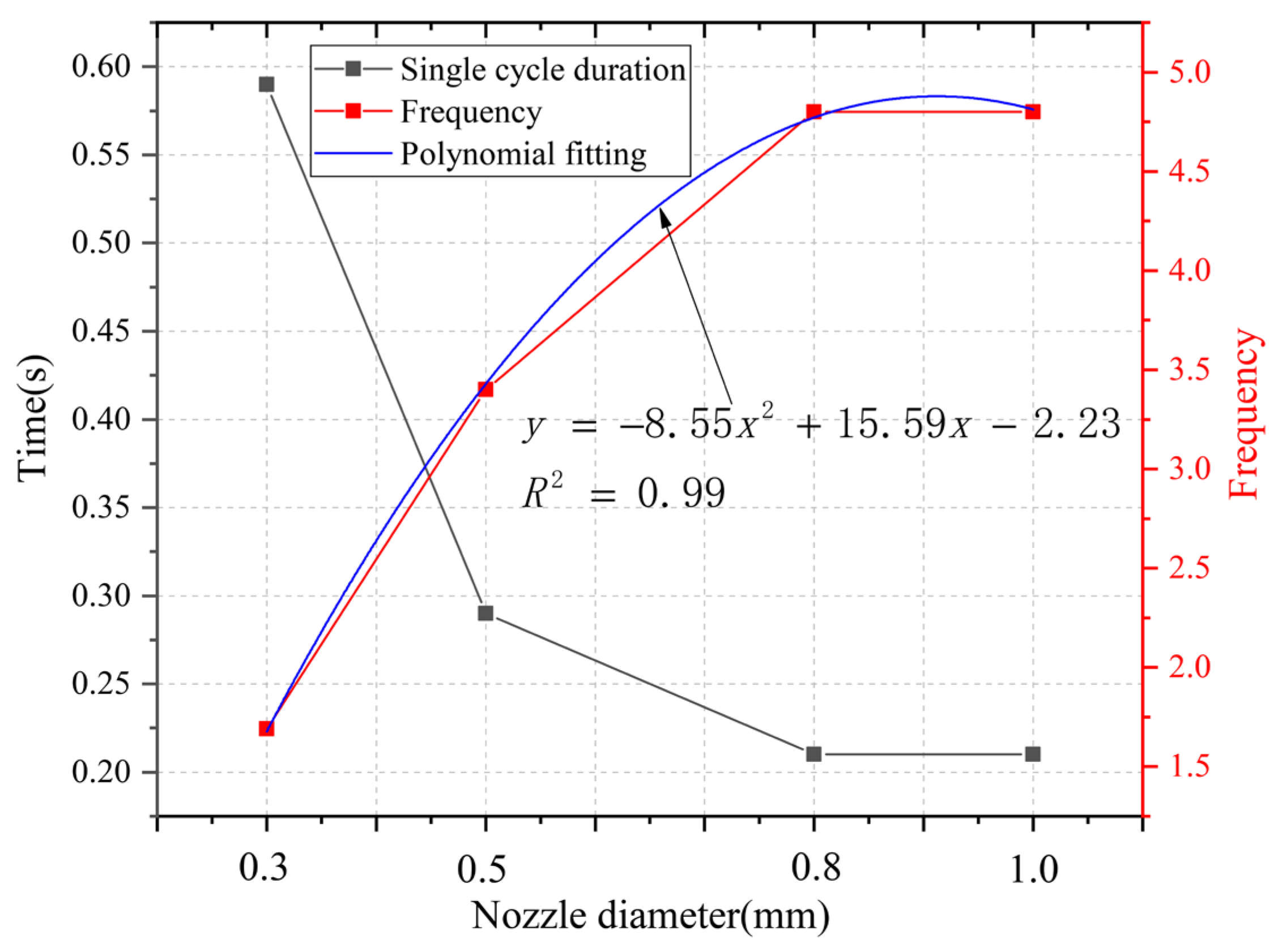
Duration and frequency of a single cycle. In Figure 11, it can be seen that as the diameter of the nozzle outlet increases, the duration of a single cycle in the supercharging chamber continuously decreases, and the impact frequency continuously increases, and tends to be gentle. The corresponding relationship between the nozzle diameter and the duration of a single cycle under the current operating conditions can be obtained using polynomial fitting, as shown in Equation (19):
y = 8.55 x 2 + 15.59 x 2.23
Based on the analysis results in Figure 10, it can be observed that when the nozzle diameter increases from 0.3 mm to 1.0 mm, the duration of a single cycle decreases from 0.59 s to 0.21 s. Among them, the stroke stage time decreases from 0.46 s to 0.08 s, accounting for 100% of the single cycle reduction time. That is to say that the increase in the nozzle diameter has a full impact on the turbocharging process during the stroke stage, specifically in the steady oscillation stage. Meanwhile, the impact frequency increased from 1.69 to 4.8.

4.4. The Influence of the Nozzle Diameter on the Boost Ratio

Extracting the fluid pressure cycle of the boost chamber in Figure 7, the influence of nozzle outlet diameter on the boost ratio during the boost process can be obtained, as shown in Figure 12.
From Figure 12, it can be seen that as the diameter of the nozzle outlet decreases, the pressurization ratio during the impact stage of the extrusion plunger continues to decrease. Using polynomial fitting, the corresponding relationship between the nozzle diameter and the pressurization ratio under current operating conditions can be obtained, which is:
y = 5.17 + 5.36 x 8 x 2
As the diameter of the nozzle increases, the boost ratio between the boost chamber and the driving pressure further decreases. This is because the increase in the nozzle diameter increases the flow rate of the pressurized fluid overflowing from the nozzle. The actual unit volume compression of the fluid by a variable cross-section plunger cannot be directly proportional to the stroke of the variable cross-section plunger. When the driving pressure is 12 MPa and the initial pressure of the boost chamber is 0.2 MPa, the boost ratio gradually decreases as the nozzle diameter increases, and the multiple fitting relationship is shown in Equation (20). Through the fitting equation of Equation (20), we can use this to predict whether the nozzle diameter of the pressurized pulsed water jet device can meet the requirements, or to obtain the corresponding pressurization ratio of a certain nozzle diameter.
Under the fixed structural parameters and driving parameters of the pressurized pulsed water jet generator, the theoretical pressurizing ratio of the jet is 5.8, which corresponds to a specific critical diameter of 0.6 mm. When the actual nozzle diameter is greater than the critical diameter by 0.6 mm, as shown in Figure 12, the actual pressure boost ratio is lower than the theoretical pressure boost ratio. When the nozzle diameter is 0.6 mm lower than the critical diameter, the actual pressure boost ratio is equivalent to the theoretical pressure boost ratio.
Based on the above analysis, it can be concluded that under the same driving pressure and initial pressure conditions, the size of the nozzle diameter determines the pressure pulsation amplitude and the pulsation period of the fluid in the pressurized chamber. That is, the nozzle diameter modulates both the amplitude and frequency of the fluid pressure pulsation characteristics. Therefore, the establishment of the fluid pressure during the extrusion process requires the adaptation of the corresponding diameter nozzle, which is the critical nozzle diameter. Therefore, the pressurization process of the pressurized pulse water jet generator is dependent on the nozzle.

5. Conclusions

(1)
A critical nozzle diameter equation for a pressurized pulse water jet generator has been established. There exists a critical nozzle diameter, and the specific size of the diameter depends on the theoretical boost ratio, the inlet oil flow rate, and the inlet oil pressure. The inlet oil flow rate is directly proportional to the critical nozzle diameter, the theoretical boost ratio is inversely proportional to the critical nozzle diameter, and the inlet oil pressure is inversely proportional to the critical nozzle diameter.
(2)
The critical nozzle diameter of this set of pressurized pulsed water jet generators is 0.6 mm. When the nozzle diameter is greater than the critical diameter, as the nozzle diameter increases, the pressure in the booster chamber tends to change towards a “short and narrow” trend. As the nozzle diameter increases, the peak pressure of the boost chamber decreases, the duration of a single cycle continuously decreases, and the frequency increases.
(3)
When the nozzle diameter is less than the critical diameter, as the nozzle diameter increases, the peak pressure in the booster chamber tends to decrease, but the reduction amplitude is weak. The duration of a single cycle gradually decreases and the frequency increases. The nozzle is not involved in the device pressurization process but provides a load for the establishment of the pressurization chamber pressure, which is dependent on the nozzle diameter. Therefore, in order to obtain a higher output pressure, we should choose a nozzle with a diameter that is smaller than the critical diameter. At the same time, a large nozzle diameter can output more energy. We should finally choose a nozzle diameter that is similar to the critical diameter, such as 0.6 mm, 0.5 mm, or 0.55 mm.

Author Contributions

Conceptualization, Y.Z. and S.M.; methodology, Y.Z. and S.M.; validation, Y.Z. and S.M.; formal analysis, Y.Z.; investigation, Y.Z. and S.M.; resources, S.M. and Y.Z.; data curation, Y.Z.; writing—original draft preparation, Y.Z.; writing—review and editing, Y.Z. and S.M.; visualization, Y.Z.; supervision, Y.Z.; project administration, Y.Z.; funding acquisition, S.M. All authors have read and agreed to the published version of the manuscript.

Funding

This research was funded by the 2023 Wuhu Science and Technology Plan Project, funder: Wuhu City Science and Technology Bureau, Project Information: Structural optimization research on abrasive nozzle based on abrasive water jet technology for machining aeroengine integral turbine bladed discs (2023yf111), the 2024 Anhui Provincial Department of Education College Young and Middle aged Teacher Training Action Project, funder: Anhui Province Department of Education, Project Information: Structural optimization of abrasive nozzle based on abrasive waterjet machining technology for aeroengine integral turbine bladed disk (YQYB2023087), and the 2024 Henan Province Science and Technology Research Projects, funder: Henan Province Science and Technology Department, Project Information: Study on Mechanism of Strengthening TBM Hob Breaking Hard Rock by Volume Modification of Pulsed Water Jet (242102220062).

Data Availability Statement

The data presented in this study are available in the article.

Acknowledgments

We are very grateful to Yuanfei Ling of Chongqing University for his experiment.

Conflicts of Interest

Author Yangkai Zhang was employed by the company China Railway Tunnel Group Co., Ltd. The remaining authors declare that the research was conducted in the absence of any commercial or financial relationships that could be construed as a potential conflict of interest.

References

  1. Lu, J.; Gong, Q.; Yin, L.; Thuro, K.; Su, G. True-triaxial experimental study on the brittle failure of granite conditioned by the TBM disc cutter. Int. J. Rock Mech. Min. Sci. 2023, 170, 105477. [Google Scholar] [CrossRef]
  2. Afrasiabi, N.; Rafiee, R.; Noroozi, M. Investigating the effect of discontinuity geometrical parameters on the TBM performance in hard rock. Tunn. Undergr. Space Technol. 2019, 84, 326–333. [Google Scholar] [CrossRef]
  3. Wu, Z.; Lei, L.; Su, Y.; Yang, K.; Zheng, J.; Zhou, Z. Limpet radula-inspired triangular groove TBM cutter for hard rock breakage with low specific wear. Tribol. Int. 2023, 187, 108721. [Google Scholar] [CrossRef]
  4. Xia, Y.; Yin, X.; Fu, J.; Liu, Y.; Cui, J.; Zhang, H. Study on the distribution and variation of temperature field in the rock breaking process of TBM disc cutter. Int. J. Therm. Sci. 2023, 186, 108086. [Google Scholar] [CrossRef]
  5. Zheng, Y.-L.; He, L. TBM tunneling in extremely hard and abrasive rocks: Problems, solutions and assisting methods. J. Cent. South Univ. 2021, 28, 454–480. [Google Scholar] [CrossRef]
  6. Farrokh, E. Cutter change time and cutter consumption for rock TBMs. Tunn. Undergr. Space Technol. 2021, 114, 104000. [Google Scholar] [CrossRef]
  7. Li, B.; Zhang, B.; Hu, M.; Liu, B.; Cao, W.; Xu, B. Full-scale linear cutting tests to study the influence of pre-groove depth on rock-cutting performance by TBM disc cutter. Tunn. Undergr. Space Technol. 2022, 122, 104366. [Google Scholar] [CrossRef]
  8. Wang, H.; Xia, B.; Lu, Y.; Ge, Z.; Tang, J. Experimental study on sonic vibrating effects of cavitation water jets and its promotion effects on coalbed methane desorption. Fuel 2016, 185, 468–477. [Google Scholar] [CrossRef]
  9. Wang, T.; Yan, C.; Zheng, H.; Ke, W.; Ali, S. Optimum spacing and rock breaking efficiency of TBM double disc cutters penetrating in water-soaked mudstone with FDEM. Tunn. Undergr. Space Technol. 2023, 138, 105174. [Google Scholar] [CrossRef]
  10. Liu, J.; Ling, J.; Cai, Y.; Ju, A.; Long, W.; Zhang, X. Study on damage mechanism of concrete under water jet combined with mechanical breaking. Arch. Civ. Mech. Eng. 2023, 23, 139. [Google Scholar] [CrossRef]
  11. Liu, J.; Zhu, B.; Liu, R.; Ling, J.; Long, W.; Zhang, X. Study on parameter analysis and damage mechanism of water jet combined with mechanical cutter head breaking concrete. J. Build. Eng. 2022, 61, 105314. [Google Scholar] [CrossRef]
  12. Zhu, D.; Yu, B.; Wang, D.; Zhang, Y. Fusion of finite element and machine learning methods to predict rock shear strength parameters. J. Geophys. Eng. 2024, 21, gxae064. [Google Scholar] [CrossRef]
  13. Stoxreiter, T.; Martin, A.; Teza, D.; Galler, R. Hard rock cutting with high pressure jets in various ambient pressure regimes. Int. J. Rock Mech. Min. Sci. 2018, 108, 179–188. [Google Scholar] [CrossRef]
  14. Tripathi, R.; Hloch, S.; Chattopadhyaya, S.; Adamcik, P.; Das, A.K. An Acoustic Emission Study of Rock Disintegration by Pulsating Water-Jet. In Advances in Manufacturing Engineering and Materials; Springer: Cham, Switzerland, 2019; pp. 156–162. [Google Scholar]
  15. Lu, Y.; Zhang, Y.; Tang, J.; Yao, Q. Switching mechanism and optimisation research on a pressure-attitude adaptive adjusting coal seam water jet slotter. Int. J. Min. Sci. Technol. 2022, 32, 1167–1179. [Google Scholar] [CrossRef]
  16. Cao, S.; Ge, Z.; Zhou, Z.; Gao, F.; Liu, W.; Lu, Y. Fracturing mechanism and pore size distributions of rock subjected to water jets under in-situ stress: Breakage characteristics investigation. J. Pet. Sci. Eng. 2022, 213, 110392. [Google Scholar] [CrossRef]
  17. Cheng, J.-L.; Yang, S.-Q.; Han, W.-F.; Zhang, Z.-R.; Jiang, Z.-H.; Lu, J.-F. Experimental and numerical study on the indentation behavior of TBM disc cutter on hard-rock precutting kerfs by high-pressure abrasive water jet. Arch. Civ. Mech. Eng. 2022, 22, 37. [Google Scholar] [CrossRef]
  18. Jiang, Y.; Zeng, J.; Xu, C.; Xiong, F.; Pan, Y.; Chen, X.; Lei, Z. Experimental study on TBM cutter penetration damage process of highly abrasive hard rock pre-cut by high-pressure water jet. Bull. Eng. Geol. Environ. 2022, 81, 511. [Google Scholar] [CrossRef]
  19. Luo, X.; Zhang, J.; Yang, F.; He, F.; Xia, Y. Research on the hard rock cutting characteristics of disc cutter under front-mounted water jet precutting kerf conditions. Eng. Fract. Mech. 2023, 287, 109330. [Google Scholar] [CrossRef]
  20. Zhang, X.; Hu, D.; Li, J.; Pan, J.; Xia, Y.; Tian, Y. Investigation of rock breaking mechanism with TBM hob under traditional and free-face condition. Eng. Fract. Mech. 2021, 242, 107432. [Google Scholar] [CrossRef]
  21. Zhang, J.-L.; Yang, F.-W.; Cao, Z.-G.; Xia, Y.-M.; Li, Y.-C. In situ experimental study on TBM excavation with high-pressure water-jet-assisted rock breaking. J. Cent. South Univ. 2023, 29, 4066–4077. [Google Scholar] [CrossRef]
  22. Ge, Z.; Ling, Y.; Tang, J.; Lu, Y.; Zhang, Y.; Wang, L.; Yao, Q. Formation Principle and Characteristics of Self-Supercharging Pulsed Water Jet. Chin. J. Mech. Eng. 2022, 35, 51. [Google Scholar] [CrossRef]
  23. Ling, Y.; Ge, Z.; Tang, J.; Lu, Y.; Zhang, Y.; Wang, L. Development of a hydraulically controlled piston-pressurized pulsed water jet device and its application potential for hard rock breaking. Rev. Sci. Instrum. 2021, 92, 085101. [Google Scholar] [CrossRef] [PubMed]
  24. Zhang, Y.; Li, Q. Influence of Hydraulic Parameters on Multi-Stage Pulse Characteristics of Pressurized Pulsed Water Jet. Processes 2023, 11, 2502. [Google Scholar] [CrossRef]
  25. Zhang, Y.; Lu, Y.; Tang, J.; Ling, Y.; Wang, L.; Yao, Q.; Zhu, Z. Development and application of rock breaking platform with variable cross section extrusion pulsed water jet. J. Mech. Sci. Technol. 2022, 36, 2837–2848. [Google Scholar] [CrossRef]
  26. Zhang, Y.; Long, H.; Tang, J.; Ling, Y. Experimental Investigation on the Granite Erosion Characteristics of a Variable Cross-Section Squeezed Pulsed Water Jet. Appl. Sci. 2023, 13, 5393. [Google Scholar] [CrossRef]
  27. Wen, J.; Qi, Z.; Behbahani, S.S.; Pei, X.; Iseley, T. Research on the structures and hydraulic performances of the typical direct jet nozzles for water jet technology. J. Braz. Soc. Mech. Sci. Eng. 2019, 41, 570. [Google Scholar] [CrossRef]
  28. Apte, D.; Ge, M.; Coutier-Delgosha, O. Numerical investigation of a cavitating nozzle for jetting and rock erosion based on different turbulence models. Geoenergy Sci. Eng. 2023, 231, 212300. [Google Scholar] [CrossRef]
  29. Chong, D.; Zhao, Q.; Yuan, F.; Wang, W.; Chen, W.; Yan, J. Research on the steam jet length with different nozzle structures. Exp. Therm. Fluid Sci. 2015, 64, 134–141. [Google Scholar] [CrossRef]
  30. Huang, L.-Y.; Chen, Z.S. Effect of technological parameters on hydrodynamic performance of ultra-high-pressure water-jet nozzle. Appl. Ocean Res. 2022, 129, 103410. [Google Scholar] [CrossRef]
  31. Juraeva, M.; Song, D.J.; Kang, D.J. Computational optimization approach to design a water-jet nozzle for a water-jet loom using the design of experiment method. J. Mech. Sci. Technol. 2019, 33, 631–637. [Google Scholar] [CrossRef]
  32. Kumar, C.P.; Lee, K.H.; Park, T.C.; Cha, B.J.; Kim, H.D. Optimization study on pin tip diameter of an impact-pin nozzle at high pressure ratio. J. Mech. Sci. Technol. 2016, 30, 4001–4006. [Google Scholar] [CrossRef]
  33. Li, D.; Kang, Y.; Ding, X.; Wang, X.; Fang, Z. Effects of area discontinuity at nozzle inlet on the characteristics of high speed self-excited oscillation pulsed waterjets. Exp. Therm. Fluid Sci. 2016, 79, 254–265. [Google Scholar] [CrossRef]
  34. Li, D.; Kang, Y.; Ding, X.; Wang, X.; Liu, W. Effects of feeding pipe diameter on the performance of a jet-driven Helmholtz oscillator generating pulsed waterjets. J. Mech. Sci. Technol. 2017, 31, 1203–1212. [Google Scholar] [CrossRef]
  35. Liu, C.; Liu, G.; Yan, Z. Study on Cleaning Effect of Different Water Flows on the Pulsed Cavitating Jet Nozzle. Shock Vib. 2019, 2019, 1496594. [Google Scholar] [CrossRef]
  36. Marcon, A.; Melkote, S.N.; Yoda, M. Effect of nozzle size scaling in co-flow water cavitation jet peening. J. Manuf. Process. 2018, 31, 372–381. [Google Scholar] [CrossRef]
  37. Raj, P.; Hloch, S.; Tripathi, R.; Srivastava, M.; Nag, A.; Klichová, D.; Klich, J.; Hromasová, M.; Muller, M.; Miloslav, L.; et al. Investigation of sandstone erosion by continuous and pulsed water jets. J. Manuf. Process. 2019, 42, 121–130. [Google Scholar] [CrossRef]
  38. Říha, Z.; Zeleňák, M.; Kruml, T.; Poloprudský, J. Comparison of the disintegration abilities of modulated and continuous water jets. Wear 2021, 478–479, 203891. [Google Scholar] [CrossRef]
  39. Song, X.; Lv, Z.; Li, G.; Hu, X.; Shi, Y. Numerical analysis of characteristics of multi-orifice nozzle hydrothermal jet impact flow field and heat transfer. J. Nat. Gas Sci. Eng. 2016, 35, 79–88. [Google Scholar] [CrossRef]
  40. Sripanagul, G.; Matthujak, A.; Sriveerakul, T.; Phongthanapanich, S. Experimental investigation of stone drilling using water jet generated by electromagnetic actuator. Int. J. Rock Mech. Min. Sci. 2021, 142, 104697. [Google Scholar] [CrossRef]
  41. Srivastava, M.; Nag, A.; Chattopadhyaya, S.; Hloch, S. Standoff Distance in Ultrasonic Pulsating Water Jet. Materials 2020, 14, 88. [Google Scholar] [CrossRef]
  42. Tripathi, R.; Hloch, S.; Chattopadhyaya, S.; Klichová, D.; Ščučka, J.; Das, A.K. Application of the pulsating and continous water jet for granite erosion. Int. J. Rock Mech. Min. Sci. 2020, 126, 104209. [Google Scholar] [CrossRef]
  43. Wang, Z.A.; Kang, Y.; Wang, X.; Li, D.; Shi, H. Effects of modulation position on the impact performance of mechanically modulated pulsed water jet. J. Manuf. Process. 2020, 56, 510–521. [Google Scholar] [CrossRef]
  44. Xu, Y.; Liu, H.; Wang, Z.; Zhang, J.; Wang, J. Analysis of the Effects of Nozzle Geometry on the Cavitation Water Jet Flow Field Using Orthogonal Decomposition, Iranian Journal of Science and Technology. Trans. Mech. Eng. 2024, 48, 119–132. [Google Scholar]
  45. Zeleňák, M.; Říha, Z.; Jandačka, P. Visualization and velocity analysis of a high-speed modulated water jet generated by a hydrodynamic nozzle. Measurement 2020, 159, 107753. [Google Scholar] [CrossRef]
Figure 1. Structure and physical diagram of a pressurized pulse water jet generator.
Processes 12 01708 g001
Figure 2. Simplified schematic diagram of a pressurized pulse water jet generator.
Processes 12 01708 g002
Figure 3. Pressure acquisition system for the pressurized pulse water jet generator.
Processes 12 01708 g003
Figure 4. Power source: (a) shows the experimental hydraulic pump. The words in (a) mean the ZY-750 hydraulic pump for coal mine drilling rigs, and (b) shows the experimental water pump.
Processes 12 01708 g004
Figure 5. Pressure acquisition device.
Processes 12 01708 g005
Figure 6. Nozzles.
Figure 6. Nozzles.
Processes 12 01708 g006
Figure 7. Pressure changes in the boost chamber under different nozzle diameters.
Processes 12 01708 g007
Figure 8. Transient response indicators of pressure pulse characteristics within a single cycle.
Processes 12 01708 g008
Figure 10. Effect of the nozzle diameter on the duration. (a) shows the change trend of the time during the pressure rise period with the nozzle diameter, (b) shows the change trend of the pressure continuous oscillation time with the nozzle diameter, (c) shows the change trend of the time during the pressure fall period with the nozzle diameter, (d) shows the change trend of the stroke time with the nozzle diameter, and (e) shows the change trend of the return time with the nozzle diameter.
Processes 12 01708 g010
Figure 11. Effect of the nozzle diameter on the single cycle duration and pulse frequency.
Processes 12 01708 g011
Figure 12. Effect of the nozzle diameter on the boost ratio.
Processes 12 01708 g012
Table 1. Pressure collection experiment scheme.
Oil Inlet Pressure (MPa)Water Inlet Pressure (MPa)Nozzle Diameter (mm)
120.20.3, 0.5, 0.8, 1.0
Disclaimer/Publisher’s Note: The statements, opinions and data contained in all publications are solely those of the individual author(s) and contributor(s) and not of MDPI and/or the editor(s). MDPI and/or the editor(s) disclaim responsibility for any injury to people or property resulting from any ideas, methods, instructions or products referred to in the content.

