
Experimental Study on the Mechanical Properties of Nano-Silicon-Modified Polyurethane Crack Repair Materials


Abstract
1. Introduction
2. Materials and Methods
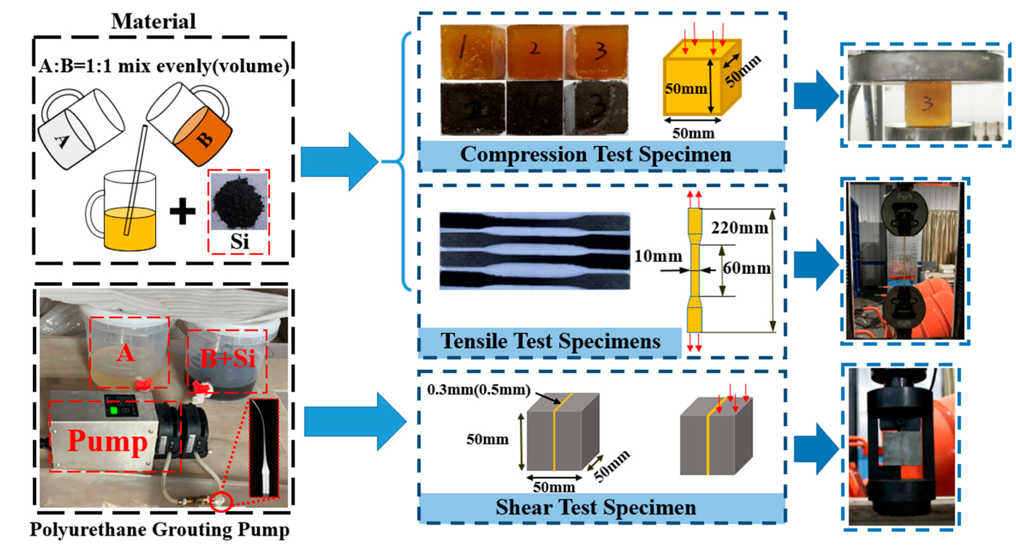
2.1. Materials
2.2. Methods
3. Test Results
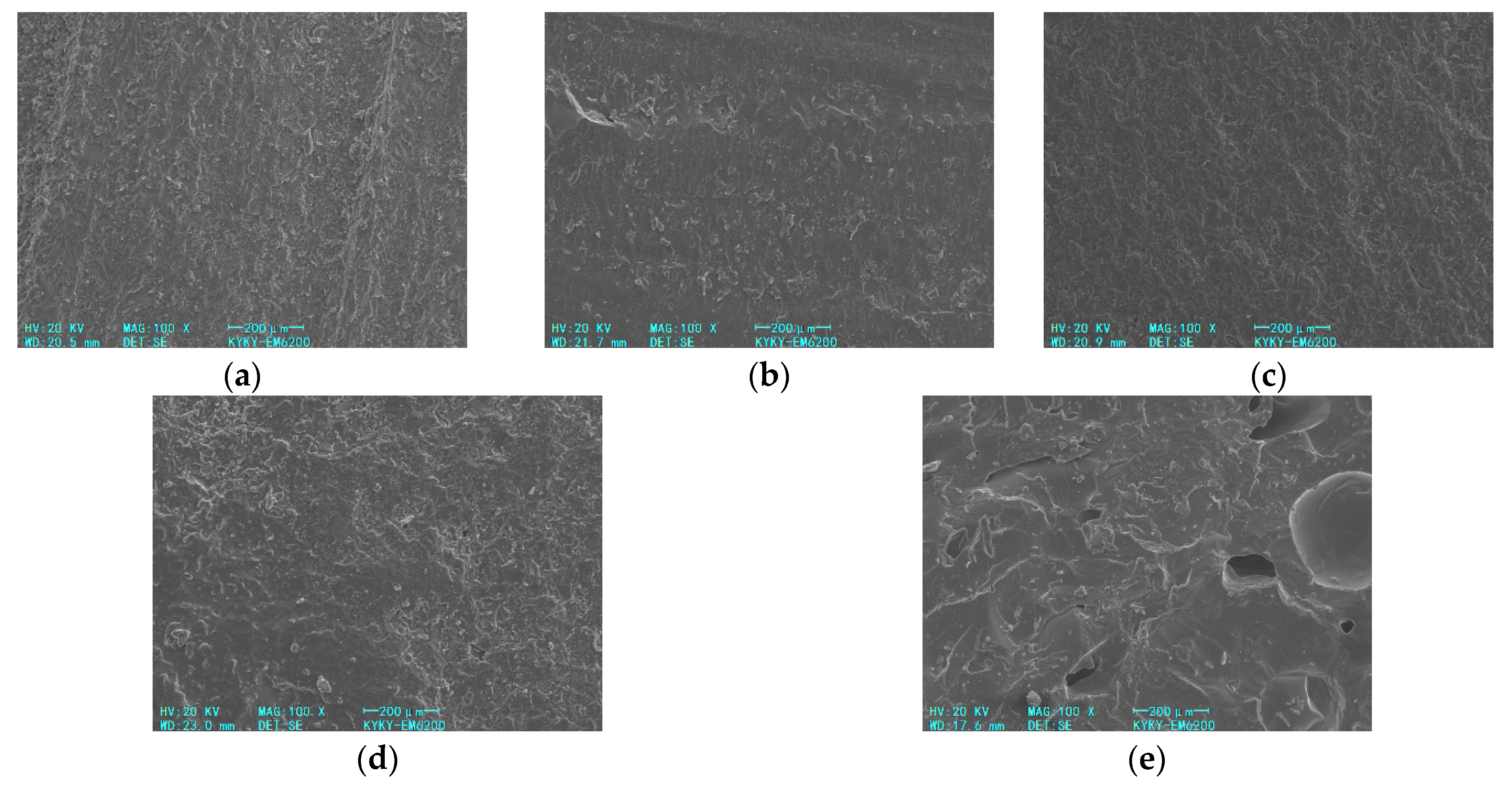
3.1. SEM Images
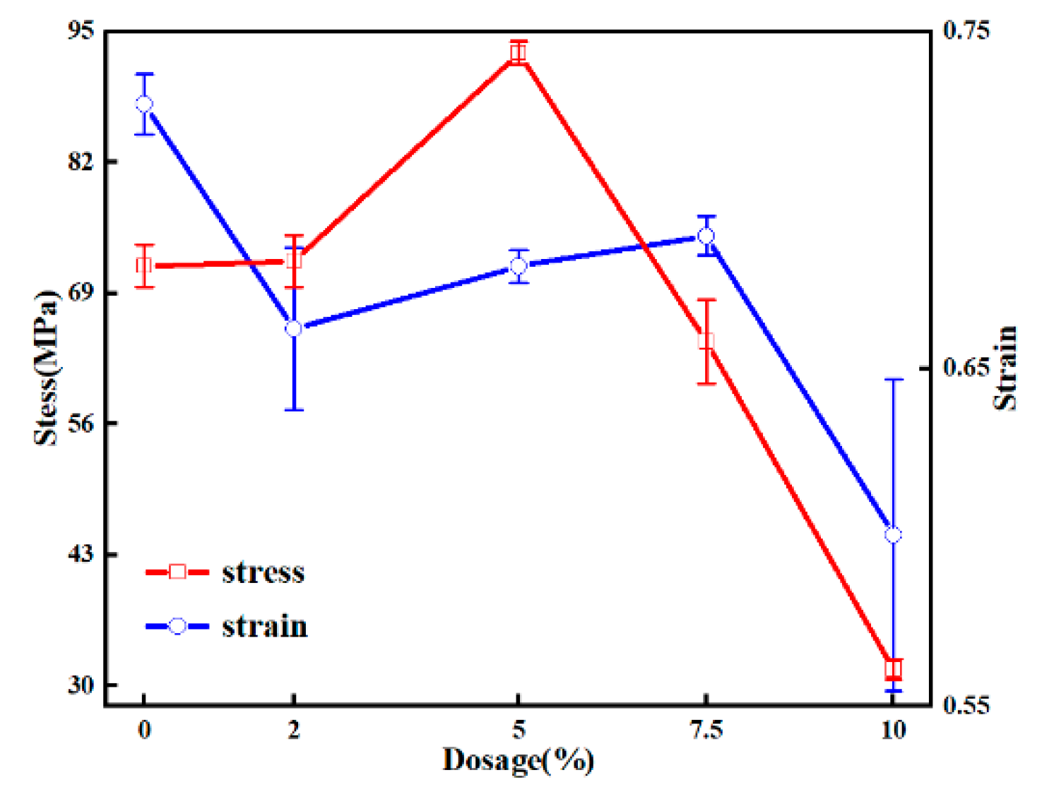
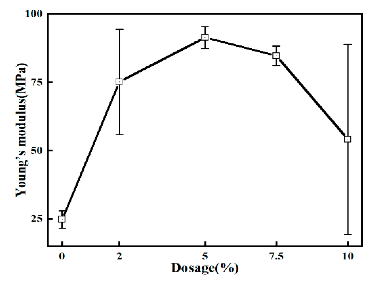
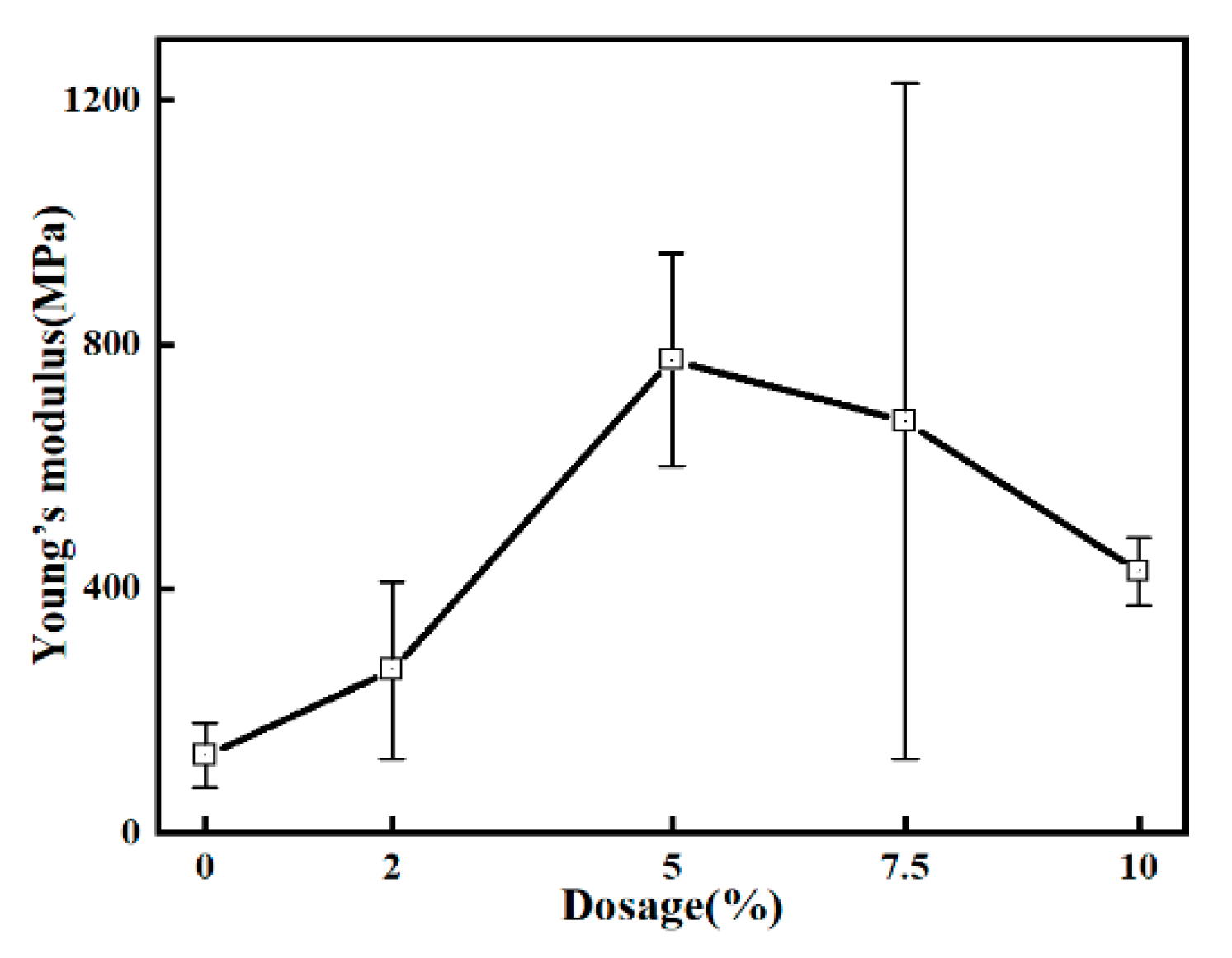
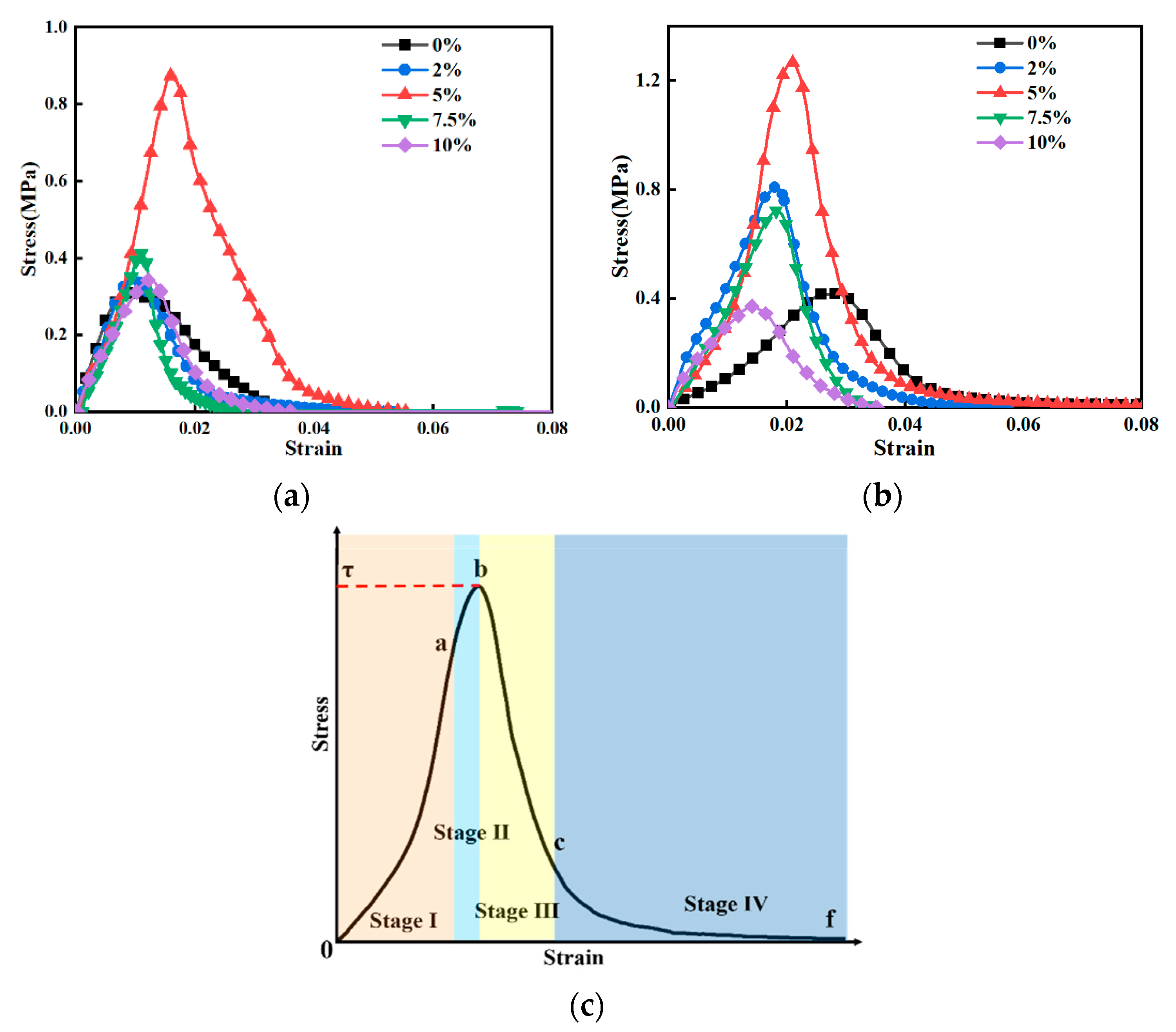
3.2. Compression Properties
3.3. Tensile Properties
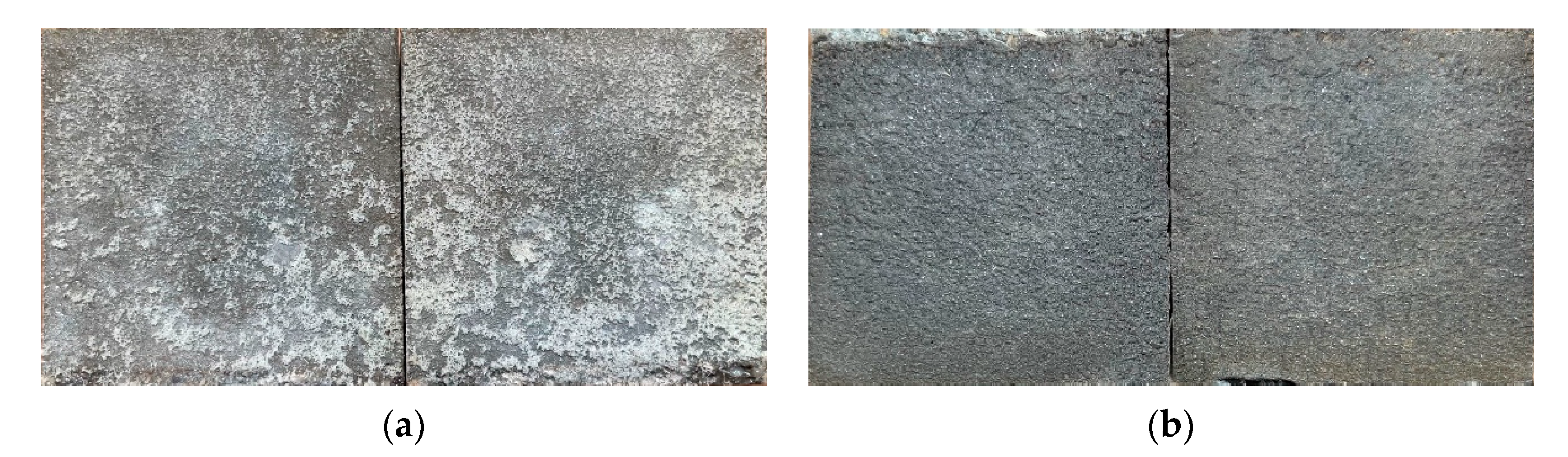
3.4. Shear Properties
4. Conclusions
Author Contributions
Funding
Data Availability Statement
Conflicts of Interest
References
- Ministry of Water Resources of the People’s Republic of China. 2022 China Water Resources Bulletin; China Water&Power Press: Beijing, China, 2022. [Google Scholar]
- Cai, Z.Y.; Chen, H.; Huang, Y.H.; Zhang, C. Failure mechanism of canal slopes of expansive soils considering action wetting-drying cycles. Chin. J. Geotech. Eng. 2019, 41, 1977–1982. [Google Scholar] [CrossRef]
- Qin, Z.P.; Lai, Y.M.; Tian, Y.; Yu, F. Frost-heaving mechanical model for concrete face slabs of earthen dams in cold regions. Cold Reg. Sci. Technol. 2019, 161, 91–98. [Google Scholar] [CrossRef]
- Li, X.J. Studies on the Movement of Soil Moisture on Canal Base in the Process of Freezing-Thawing and Frost Resistance Theory and Technology of Large-Arc Canal Seepage Control. Doctor’s Thesis, Xi’An University of Technology, Xi’an, China, 2011. [Google Scholar]
- He, P.F.; Ma, W.; Mu, Y.H.; Dong, J.H.; Huang, Y.T. Elastic foundation beam model for frost heave damage of trapezoidal canal lining considering frost heave force and adfreeze force. J. Cent. South Univ. (Sci. Technol.) 2021, 52, 4148–4157. [Google Scholar] [CrossRef]
- Liu, H.; Li, A.; Huang, H.L.; Song, X.F.; Wu, J.; Chen, Y.; Gao, P.; Hu, J.; Wei, J.X.; Yu, Q.J. Gradient microstructure and strain field at interfacial zone between cement-based repair and concrete substrate. Compos. Part B Eng. 2023, 260, 110775. [Google Scholar] [CrossRef]
- Zhang, W.; Zheng, Q.F.; Ashour, A.; Han, B.G. Self-healing cement concrete composites for resilient infrastructures: A review. Compos. Part B Eng. 2020, 189, 107892. [Google Scholar] [CrossRef]
- Fronczyk, J.; Janek, M.; Szeląg, M.; Pyzik, A.; Franus, W. Immobilization of (bio-) healing agents for self-healing concrete technology: Does it really ensure long-term performance? Compos. Part B Eng. 2023, 266, 110997. [Google Scholar] [CrossRef]
- Jonkers, H.M.; Thijssen, A.; Muyzer, G.; Copuroglu, O.; Schlangen, E. Application of bacteria as self-healing agent for the development of sustainable concrete. Ecol. Eng. 2010, 36, 230–235. [Google Scholar] [CrossRef]
- Hilloulin, B.; Tittelboom, K.V.; Gruyaert, E.; Belie, N.D.; Loukili, A. Design of polymeric capsules for self-healing concrete. Cem. Concr. Compos. 2015, 55, 298–307. [Google Scholar] [CrossRef]
- White, S.R.; Sottos, N.R.; Geubelle, P.H.; Moore, J.S.; Kessler, M.R.; Sriram, S.R.; Brown, E.N.; Viswanathan, S. Autonomic healing of polymer composites. Nature 2001, 409, 794–797. [Google Scholar] [CrossRef]
- Wang, J.Y.; Tittelboom, K.V.; Belie, N.D.; Verstraete, W. Use of silica gel or polyurethane immobilized bacteria for self-healing concrete. Constr. Build. Mater. 2012, 26, 532–540. [Google Scholar] [CrossRef]
- Kim, T.K.; Park, J.S. Comparative analysis of domestic and international test guidelines for various concrete repair materials. Materials 2022, 15, 3267. [Google Scholar] [CrossRef]
- Jia, Q.; Zhang, X.; Hou, H.T.; Yang, J.B. Field experiment of crack repair by microbiological precipitation of CaCO3. J. Build. Mater. 2013, 16, 667–672. [Google Scholar] [CrossRef]
- Gomaa, E.; Gheni, A.; ElGawady, M.A. Repair of ordinary portland cement concrete using ambient-cured alkali-activated concrete: Interfacial behavior. Cem. Concr. Res. 2020, 129, 105968. [Google Scholar] [CrossRef]
- Li, H.; Yang, H.; Li, X. Investigation on the working performance of a non-dispersible grouting material for the crack repairment of underwater structures. Constr. Build. Mater. 2023, 407, 133558. [Google Scholar] [CrossRef]
- Lee, W.J.; Oh, H.G.; Cha, S.H. A brief review of self-healing polyurethane based on dynamic chemistry. Macromol. Res. 2021, 29, 649–664. [Google Scholar] [CrossRef]
- Wu, S.Y. Dynamic Response of Polyurethane-Steel Composite Structure under Impact Loads. Master’s Dissertation, Harbin Engineering University, Harbin, China, 2023. [Google Scholar]
- Bourbigot, S.; Turf, T.; Bellayer, S.; Duquesne, S. Polyhedral oligomeric silsesquioxane as flame retardant for thermoplastic polyurethane. Polym. Degrad. Stab. 2009, 94, 1230–1237. [Google Scholar] [CrossRef]
- Xiong, Z.R. Preparation and Application of Self-Healing Polyurethane Composites. Doctor’s Dissertation, University of Science and Technology of China, Hefei, China, 2023. [Google Scholar]
- Jiang, Z.H.; Cai, H.Y.; Chen, X.L.; Gong, S.; Liu, D.Y.; Pang, Y.J.; Xiong, Y.; Zhu, Z.H.; Li, Z. Improving the mechanical and damping properties of polymer/memory alloy composite by introducing nanotubes covered with nano-scale Ni particles. Compos. Part A Appl. Sci. Manuf. 2022, 156, 106856. [Google Scholar] [CrossRef]
- Hu, F.; Gao, J.; Zhang, B.; Qi, F.G.; Zhao, N.; Ouyang, X.P. Effects of modified Al2O3-decorated ionic liquid on the mechanical properties and impact resistance of a polyurethane elastomer. Materials 2021, 14, 4712. [Google Scholar] [CrossRef]
- Chen, H.Q. Surface treatment of nano/micro materials and its application in polymer base composites. Doctor’s Dissertation, Nanjing University of Science and Technology, Nanjing, China, 2004. [Google Scholar]
- Chen, W.; Tao, X.M.; Liu, Y.Y. Carbon nanotube-reinforced polyurethane composite fibers. Compos. Sci. Technol. 2006, 66, 3029–3034. [Google Scholar] [CrossRef]
- Lu, H.D.; Hu, Y.; Li, M.; Chen, Z.Y.; Fan, W.C. Structure characteristics and thermal properties of silane-grafted-polyethylene/clay nanocomposite prepared by reactive extrusion. Compos. Sci. Technol. 2006, 66, 3035–3039. [Google Scholar] [CrossRef]
- Shi, Y.Q.; Liu, C.; Fu, L.B.; Feng, Y.Z.; Lv, Y.C.; Wang, Z.X.; Liu, M.H.; Chen, Z.X. Highly efficient MXene/Nano-Cu smoke suppressant towards reducing fire hazards of thermoplastic polyurethane. Compos. Part A Appl. Sci. Manuf. 2021, 150, 106600. [Google Scholar] [CrossRef]
- Song, H.J.; Zhang, Z.Z.; Men, X.H. The tribological behaviors of the polyurethane coating filled with nano-SiO2 under different lubrication conditions. Compos. Part A Appl. Sci. Manuf. 2008, 39, 188–194. [Google Scholar] [CrossRef]
- Xu, X.B.; Li, Z.M.; Shi, L.; Bian, X.C.; Xiang, Z.D. Ultralight conductive carbon-nanotube–polymer composite. Small 2007, 3, 408–411. [Google Scholar] [CrossRef]
- Choi, J.T.; Kim, D.H.; Ryu, K.S.; Lee, H.; Jeong, H.M.; Shin, C.M.; Kim, J.H.; Kim, B.K. Functionalized graphene sheet/polyurethane nanocomposites: Effect of particle size on physical properties. Macromol. Res. 2011, 19, 809–814. [Google Scholar] [CrossRef]
- Liu, F.C.; Han, H.E.; Ke, W. Research of photocatalytic activity of nano-TiO2/polyurethane composite coating. J. Funct. Mater. 2005, 36, 129–132. [Google Scholar] [CrossRef]
- Charpentier, P.A.; Burgess, K.; Wang, L.; Chowdhury, R.R.; Lotus, A.F.; Moula, G. Nano-TiO2/polyurethane composites for antibacterial and self-cleaning coatings. Nanotechnology 2012, 23, 425606. [Google Scholar] [CrossRef]
- Gao, X.Y. The Study of the Preparation and Property of Inorganic Polyurethane Nanocomposites. Doctor’s Dissertation, Jilin University, Jilin, China, 2011. [Google Scholar]
- He, D.; Qin, Q.; Zhou, H.W.; Li, J.H.; Zheng, H.; Yi, Y. Preparation and characterization of hybrid polyurethane/Organic montmorillonite nanocomposites. Polym. Mater. Sci. Eng. 2015, 31, 139–143. [Google Scholar]
- Ye, Y.P.; Zhang, Y.S.; Sun, X.J.; Zhou, H.D. Preparation and tribological behavior of Ni/Polyurethane nanocomposite coatings. Tribology 2003, 23(2), 104–107. [Google Scholar] [CrossRef]
- Hsu, S.H.; Tseng, H.J.; Lin, Y.C. The biocompatibility and antibacterial properties of waterborne polyurethane-silver nanocomposites. Biomaterials 2010, 31, 6796–6808. [Google Scholar] [CrossRef] [PubMed]
- Li, Q.F.; Yu, Y.H.; Yang, Q.Q.; Ma, J.F.; Jin, R.G. A study on the infrared characteristic and mechanical properties of polyurethane/nano materials. Polym. Mater. Sci. Eng. 2002, 18, 110–113. [Google Scholar] [CrossRef]
- Akbarian, M.; Olya, M.E.; Ataeefard, M.; Mahdavian, M. The influence of nanosilver on thermal and antibacterial properties of a 2 K waterborne polyurethane coating. Prog. Org. Coat. 2012, 75, 344–348. [Google Scholar] [CrossRef]
- Zhong, Y.K. Study on Synthesis and Properties of Silicone Modified Waterborne Polyester. Master’s Dissertation, Nanjing Tech University, Nanjing, China, 2008. [Google Scholar]
- Yu, Z.S. Experimental Study on Mechanical Properties of Non-Foaming Polymer Grouting Materials. Master’s Dissertation, Zhengzhou University, Zhengzhou, China, 2020. [Google Scholar]
- Pan, W.W.; Xia, Y.Y.; Zhang, C.; Fang, H.Y.; Wang, F.M. Compression size effect and strain rate effect of a new polyurethane elastomer grouting material. Mater. Rep. 2023, 37, 273–279. [Google Scholar] [CrossRef]
- Wang, F.M.; Guo, C.C.; Yu, J.H.; Tong, M.; Zeng, W.L.; Jiang, X.X. An Environmentally Friendly Low-Viscosity Polyurethane Grouting Reinforcement Material and Its Preparation Method. CN116693804A, 5 September 2023. [Google Scholar]
- GB/T 20219-2015; Rigid Cellular Plastics-Spray-Applied Polyurethane Foam for Thermal Insulation. Standards Press of China: Beijing, China, 2015.
- GB/T 2567-2021; Test Methods for Properties of Resin Casting Body. Standards Press of China: Beijing, China, 2021.
- MacLachlan, M.J.; Manners, I.; Ozin, G.A. New (inter) faces: Polymers and inorganic materials. Adv. Mater. 2000, 12, 675–681. [Google Scholar] [CrossRef]
- Xiao, S.; Hossain, M.M.; Liu, P.; Wang, H.L.; Hu, F.C.; Sue, H.J. Scratch behavior of model polyurethane elastomers containing different soft segment types. Mater. Des. 2017, 132, 419–429. [Google Scholar] [CrossRef]
- Zhu, S.Z.; Lempesis, N.; in ‘t Veld, P.J.; Rutledge, G.C. Molecular simulation of thermoplastic polyurethanes under large compressive deformation. Macromolecules 2018, 51, 9306–9316. [Google Scholar] [CrossRef]
- Liu, Y.H.; Wang, Y.S.; Yang, X.; Huang, W.; Li, K.; Wang, X. A review of progress on polyurethane damping materials. Mater. Rep. 2023, 37, 522–528. [Google Scholar]
- Wan, L.Y.; Xiao, L. Research progress of polymer damping materials. Polym. Mater. Sci. Eng. 1999, 15, 1–5. [Google Scholar] [CrossRef]
- Fu, S.Y.; Feng, X.Q.; Lauke, B.; Mai, Y.M. Effects of particle size, particle/matrix interface adhesion and particle loading on mechanical properties of particulate–polymer composites. Compos. Part B Eng. 2008, 39, 933–961. [Google Scholar] [CrossRef]
- Tonelli, M.; Gelli, R.; Ridi, F.; Baglioni, P. Magnesium phosphate-based cements containing Halloysite nanotubes for cracks repair. Constr. Build. Mater. 2021, 301, 124056. [Google Scholar] [CrossRef]
- Li, S.C.; Zhang, J.; Li, Z.F.; Gao, Y.F.; Qi, Y.H.; Li, H.Y.; Zhang, Q.S. Investigation and practical application of a new cementitious anti-washout grouting material. Constr. Build. Mater. 2019, 224, 66–77. [Google Scholar] [CrossRef]
- Cui, W.; Huang, J.Y.; Song, H.F.; Xiao, M. Development of two new anti-washout grouting materials using multi-way ANOVA in conjunction with grey relational analysis. Constr. Build. Mater. 2017, 156, 184–198. [Google Scholar] [CrossRef]
- Song, B.D.; Park, B.G.; Choi, Y.; Kim, T.H. Determining the engineering characteristics of the Hi-FA series of grout materials in an underwater condition. Constr. Build. Mater. 2017, 144, 74–85. [Google Scholar] [CrossRef]


| Main Ingredients | Catalysts | Surfactant | Diluent | Flame Retardant | |
|---|---|---|---|---|---|
| Component A | Polyether polyol | Triethylamine, Diethylenetriamine | Polyoxyethylene-based nonionic active agent | Dibutyl phthalate | \ |
| Component B | Isocyanate | \ | \ | Dichloromethane, Dimethyl carbonate | Trimethyl phosphate |
| Properties/Units | Polyurethane | ECA [16] | Carbon Nanotube Cement [50] | CIS [51] | AWG [52] | Hi-FA [53] | Nano-Polyurethane |
|---|---|---|---|---|---|---|---|
| Compressive (MPa) | 71.5 | 85.66 (28 d) | 65 (10 d) | 15 (28 d) | 17 (90 d) | 35 (28 d) | 92.5 |
| Tensile (MPa) | 3.3 | 6.18 (3 d) | \ | \ | \ | \ | 11.8 |
| Shear (MPa) | 0.42 | \ | \ | \ | \ | \ | 1.27 |
Disclaimer/Publisher’s Note: The statements, opinions and data contained in all publications are solely those of the individual author(s) and contributor(s) and not of MDPI and/or the editor(s). MDPI and/or the editor(s) disclaim responsibility for any injury to people or property resulting from any ideas, methods, instructions or products referred to in the content. |
© 2024 by the authors. Licensee MDPI, Basel, Switzerland. This article is an open access article distributed under the terms and conditions of the Creative Commons Attribution (CC BY) license (https://creativecommons.org/licenses/by/4.0/).
Share and Cite
Fan, B.; Li, X.; Xu, S.; Zhong, Y.; Zhang, B.; Liu, X. Experimental Study on the Mechanical Properties of Nano-Silicon-Modified Polyurethane Crack Repair Materials. Processes 2024, 12, 1735. https://doi.org/10.3390/pr12081735
Fan B, Li X, Xu S, Zhong Y, Zhang B, Liu X. Experimental Study on the Mechanical Properties of Nano-Silicon-Modified Polyurethane Crack Repair Materials. Processes. 2024; 12(8):1735. https://doi.org/10.3390/pr12081735
Chicago/Turabian StyleFan, Bingsen, Xiaolong Li, Shengjie Xu, Yanhui Zhong, Bei Zhang, and Xiaofeng Liu. 2024. "Experimental Study on the Mechanical Properties of Nano-Silicon-Modified Polyurethane Crack Repair Materials" Processes 12, no. 8: 1735. https://doi.org/10.3390/pr12081735
APA StyleFan, B., Li, X., Xu, S., Zhong, Y., Zhang, B., & Liu, X. (2024). Experimental Study on the Mechanical Properties of Nano-Silicon-Modified Polyurethane Crack Repair Materials. Processes, 12(8), 1735. https://doi.org/10.3390/pr12081735