
Research and Application for Alternate Production Technology of Dual-Branch Horizontal Wells in an Offshore Oilfield

Abstract
1. Introduction
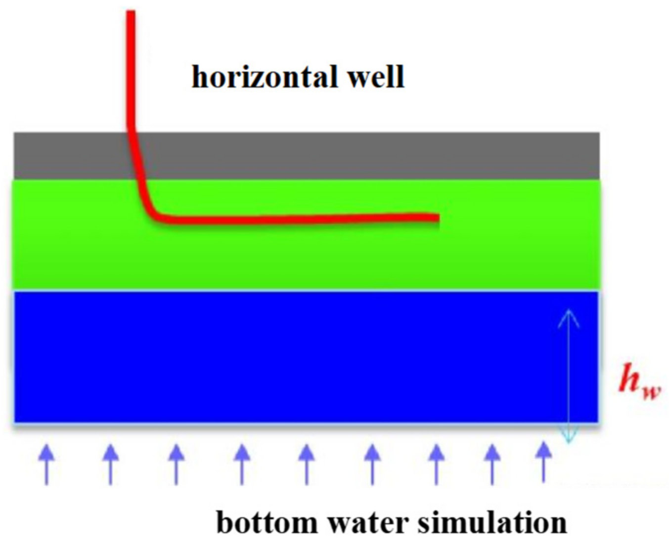
2. Research on the Drainage Radius of Horizontal Wells in Bottom-Water Reservoirs
2.1. The Drainage Radius Based on Reservoir Engineering Methods
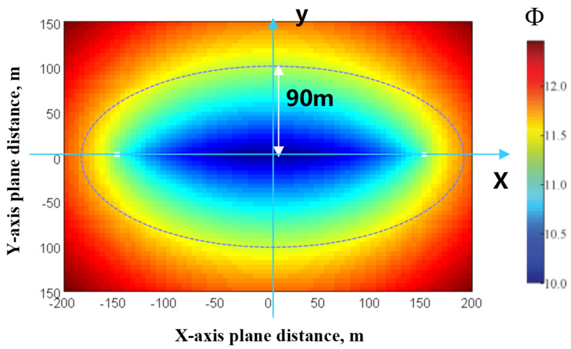
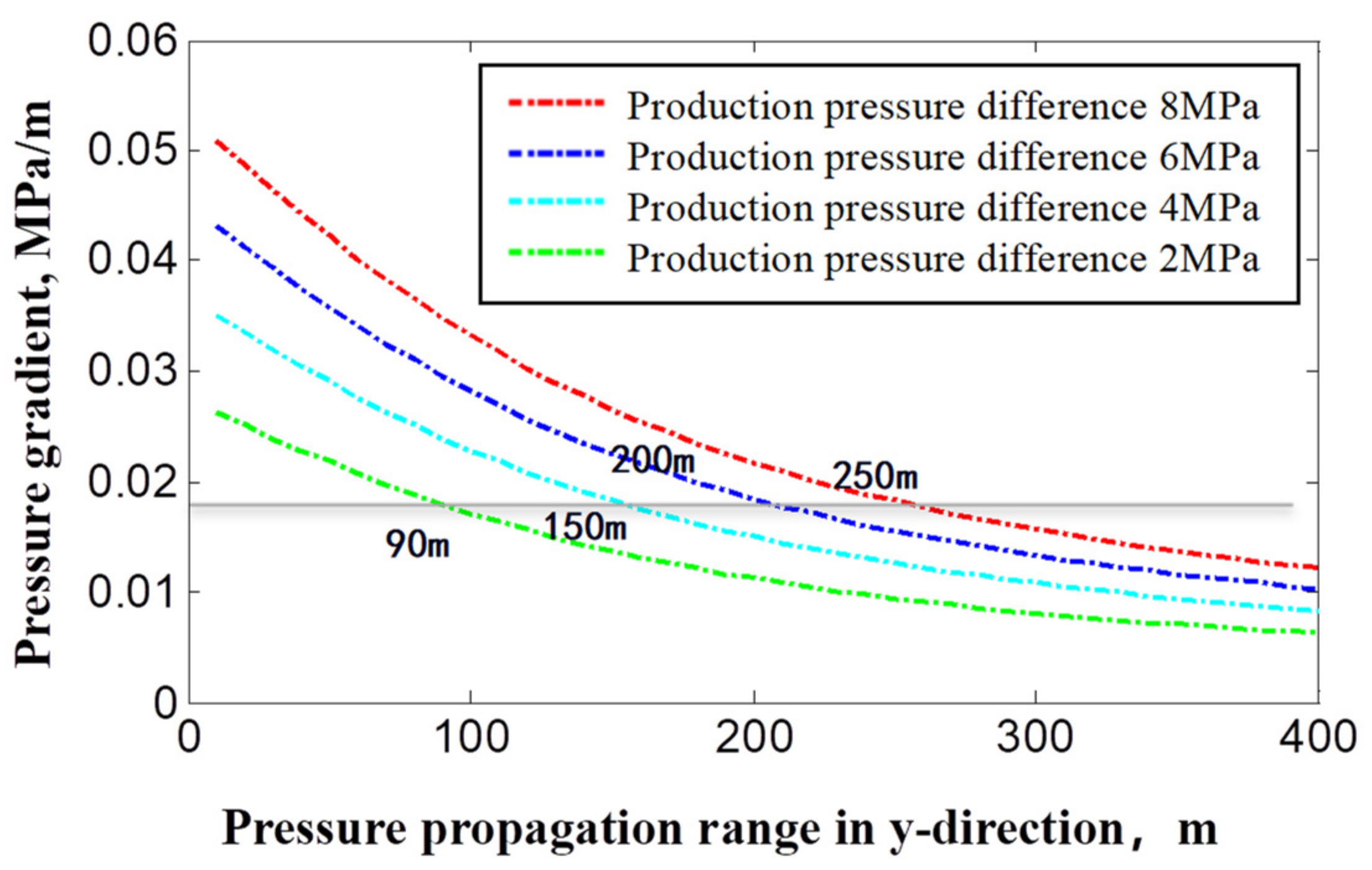
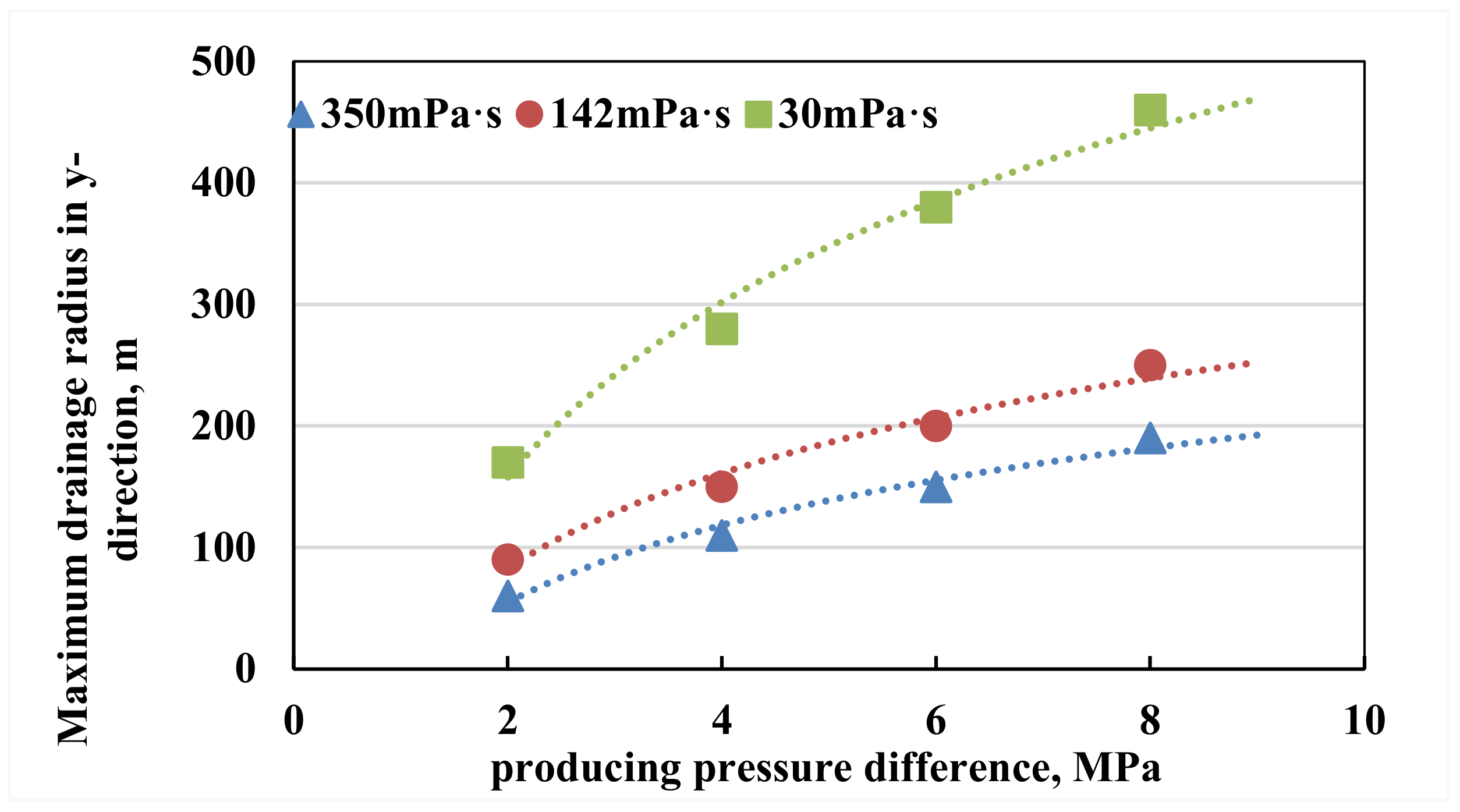
2.2. Establishment of the Maximum Drainage Radius Chart of Horizontal Wells
3. Research on Natural Shut-In Coning Control Mechanism in Bottom-Water Reservoirs
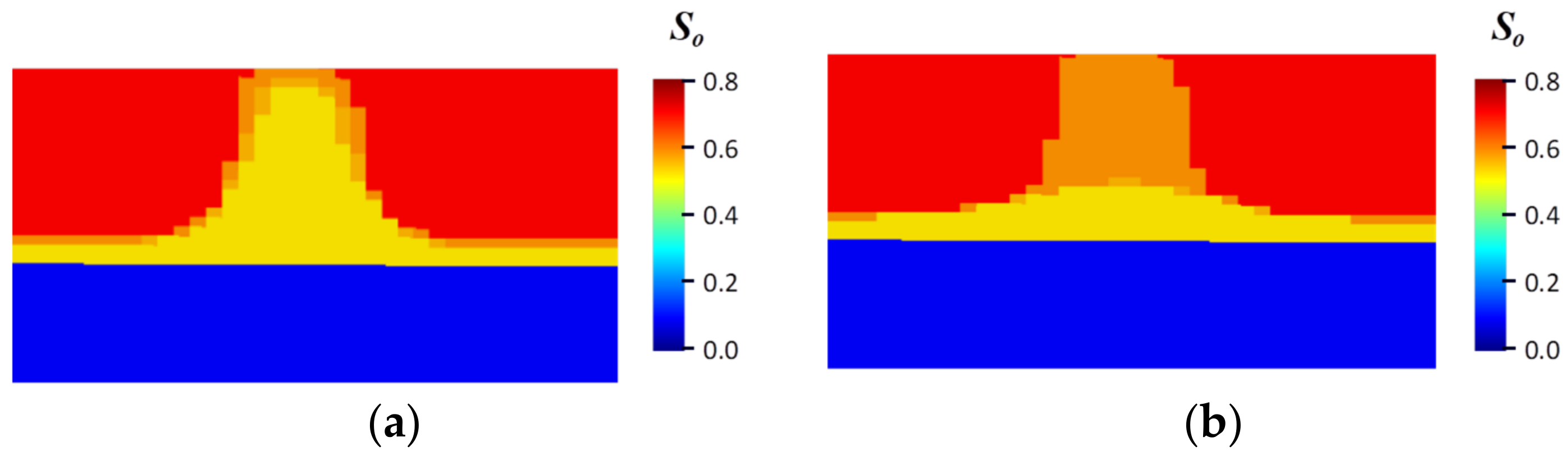
3.1. The Natural Shut-In Coning Control Mechanism Research Based on Numerical Simulation Methods
3.2. The Analysis of Natural Shut-In Coning Control of Horizontal Wells in Bottom-Water Reservoirs
4. Research and Application of the Alternate Production Technology with Dual-Branch Horizontal Well in Bottom-Water Reservoirs
4.1. A Brief Introduction of the Construction Process
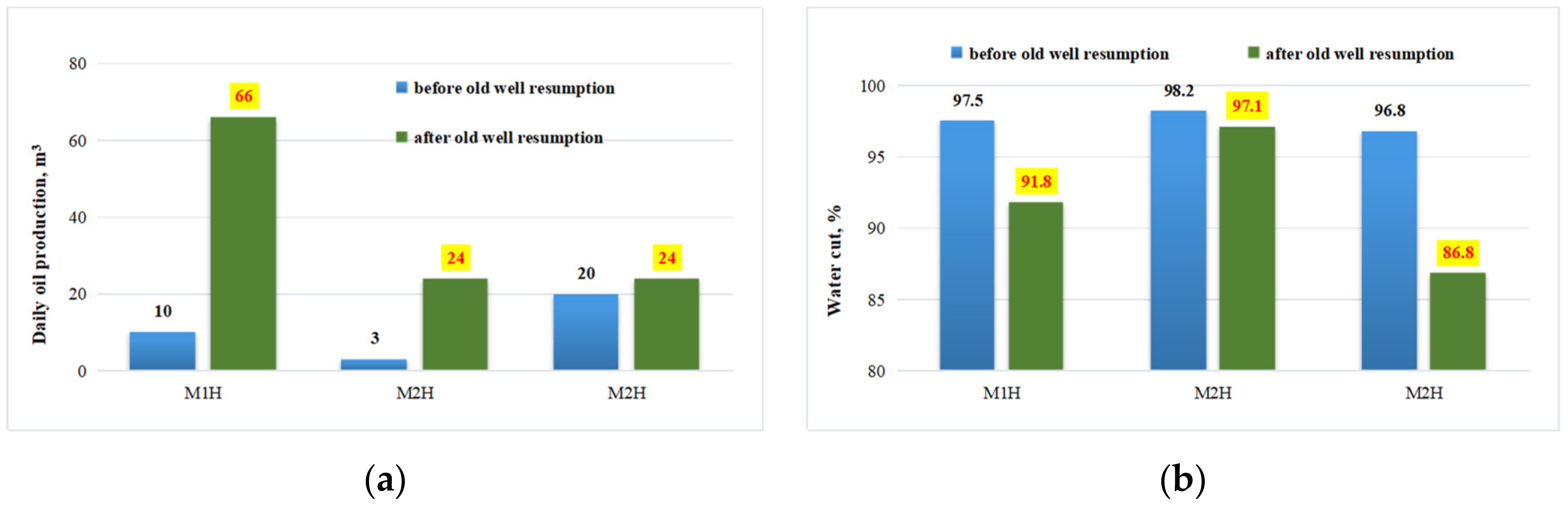
4.2. The Implementation Effect of Alternate Production Technology with Dual-Branch Horizontal Wells
5. Conclusions
Author Contributions
Funding
Data Availability Statement
Acknowledgments
Conflicts of Interest
References
- Zhang, N.; An, Y.; Huo, R. Research on Production Performance Prediction Model of Horizontal Wells Completed with AICDs in Bottom Water Reservoirs. Energies 2023, 16, 2602. [Google Scholar] [CrossRef]
- Shang, B.; Han, X.; Li, S.; Liu, K. Research of water control technology for horizontal wells in water-driven reservoirs. Adv. Geo-Energy Res. 2018, 2, 210–217. [Google Scholar] [CrossRef]
- Sun, G.; Zhang, J.; Lei, Y.; Wang, Y.; Chang, H.; Zhai, S. Numerical Simulation Study for Water Breakthrough Law of Horizontal Well in Edge Water Reservoir. Adv. Pet. Explor. Dev. 2016, 11, 50–54. [Google Scholar]
- Wu, X.D.; Wang, Y.N.; Wang, R.H.; Zhang, H.H.; Qi, B.L.; Zhu, M. Research on Horizontal Well Inhibiting Water Coning and Tapping the Potential of Remaining Oil. Appl. Mech. Mater. 2014, 527, 57–64. [Google Scholar] [CrossRef]
- Jin, B.; Shu, X.; Deng, M. Distribution and potential exploitation strategy of remaining oil in high water-cut stage, Bohai sea. Sci. Technol. Eng. 2020, 20, 6033–6040. [Google Scholar]
- Zhang, D.; Li, F.H.; Feng, X.; Liu, C.Z.; Wang, F. Study on development law of horizontal wells under the influence of bottom water thickness. Unconv. Oil Gas 2022, 9, 58–64. [Google Scholar]
- Chen, H.; Shi, H.; Guo, C.; Zheng, Y.; Ding, W.; Yang, J.; Cheng, M.; Chen, P.; Xing, Y. Optimization of Water Avoidance Height in Horizontal Wells in Carbonate Bottom Water Gas Reservoirs. In Proceedings of the International Field Exploration and Development Conference 2020, Chengdu, China, 23–25 September 2020; Springer: Berlin/Heidelberg, Germany, 2021; pp. 671–677. [Google Scholar]
- Liu, H.Z.; Li, L.C.; Wu, J. Experimental study on the rule of horizontal well water breakthrough in bottom water reservoir. J. Petrochem. Univ. 2012, 25, 57–60. [Google Scholar]
- Zhu, Y.; Wu, J.; Wu, P.; Liu, X.; Dang, Y. Indoor simulation experiment on exploitation of bottom water reservoir. Acta Pet. Sin. 2008, 29, 97–100. [Google Scholar]
- Li, S.; Liu, Y.; Xue, L.; Yang, L.; Yuan, Z.; Jian, C. An investigation on water flooding performance and pattern of porous carbonate reservoirs with bottom water. J. Pet. Sci. Eng. 2021, 200, 108353. [Google Scholar] [CrossRef]
- Hou, J.; Cheng, L.S. Calculation method for the water cone height of bottom-water reservoir. J. Xi’an Shiyou Univ. Nat. Sci. Ed. 2006, 21, 23–26. [Google Scholar]
- Tan, J.; Sun, E.; Yang, D.; Zhang, W.; Mou, S. Analysis of Factors Influencing Shut in Pressure Cone in Offshore Strong Bottom Water Reservoir. J. Geosci. Environ. Prot. 2021, 9, 166–175. [Google Scholar] [CrossRef]
- Hou, Y.; Zhang, D.; Zhu, Y.; Liu, B. The research and application of the horizontal wells’ production performance predicting model after water breakthrough in bottom water reservoir. J. Petrochem. Univ. 2016, 29, 51–55. [Google Scholar]
- Tan, J.; Liu, C.; Mou, S.; Liu, B.; Zhang, W. Numerical Simulation of Residual Oil Displacement in Offshore Strong Bottom Water Reservoir. J. Geosci. Environ. Prot. 2022, 10, 62–73. [Google Scholar] [CrossRef]
- Zhao, X.; Zhang, M.; Wang, Q.; Tan, J.; Li, B. Study on Water Ridge Variation of Horizontal Wells in Bottom Water Reservoir. J. Power Energy Eng. 2020, 8, 43–54. [Google Scholar] [CrossRef]
- Patil, R.N.; Vinjamur, M.; Mitra, S.K. The Optimization of the Length of Horizontal Wells for Bottom Water Reservoir Conditions. Energy Sources Part A Recovery Util. Environ. Eff. 2013, 35, 2337–2347. [Google Scholar] [CrossRef]
- Chen, K.; Zhao, F.; Dai, C.; Wang, Y.; Han, L.; Shi, G.; Lu, J. Controlling technique for water coning in thin oil reservoir with bottom water in Luliang Oilfield. Acta Pet. Sin. 2006, 27, 75–78. [Google Scholar]
- Caili, D.; Qing, Y.; Hanqiao, J.; Fulin, Z. A Study on Bottom Water Coning Control Technology in a Thin Reservoir. Pet. Sci. Technol. 2011, 29, 236–246. [Google Scholar] [CrossRef]
- Li, Y.; Li, H.; Li, Y. Prediction Method of Bottom Water Coning Profile and Water Breakthrough Time in Bottom Water Reservoir without Barrier. Math. Probl. Eng. Theory Methods Appl. 2015, 2015, 149490. [Google Scholar] [CrossRef]
- Zhang, D.; Sun, E.; Hou, Y.; Peng, Q.; Tan, J. The prediction and application of horizontal well drainage radius for bottom water heavy oil reservoir considering start-up pressure gradient. Unconv. Oil Gas 2019, 6, 83–88. [Google Scholar]
- Chen, H. Application of separate layer production technology in CFD oilfield. Petrochem. Technol. 2022, 3, 71–72. [Google Scholar]
- Mahjour, S.K.; Badhan, J.H.; Faroughi, S.A. Uncertainty Quantification in CO2 Trapping Mechanisms: A Case Study of PUNQ-S3 Reservoir Model Using Representative Geological Realizations and Unsupervised Machine Learning. Energies 2024, 17, 1180. [Google Scholar] [CrossRef]
- Mahjour, S.K.; Faroughi, S.A. Risks and uncertainties in carbon capture, transport, and storage projects: A comprehensive review. Gas Sci. Eng. 2023, 119, 205117. [Google Scholar]


| Oil Viscosity mPa·s | Layer Thickness m | Permeability 10−3 μm2 | Horizontal Section Length m | Pressure Difference MPa | Pressure Gradient MPa/m |
|---|---|---|---|---|---|
| 142 | 10 | 3000 | 300 | 2~8 | 0.018 |
| Oil Viscosity mPa·s | Layer Thickness m | Kv/Kh | Height of Water Avoidance m | Grid Size m | Daily Liquid Output m3/d | Bottom-Water Types |
|---|---|---|---|---|---|---|
| 3~325 | 5~20 | 0.1 | 18 | 25 × 25 × 1 | 1200 | Carter–Tracey model |
| Horizontal section length m | Porosity % | Permeability 10−3 μm2 | Bottom-water thickness m | Model dimension | Control mode | Oil density Kg/m3 |
| 400 | 30 | 1000~6000 | 2~60 | 80 × 40 × 40 | Fixed liquid rate production | 850~980 |
| Oil Viscosity mPa·s | 100~425 | 50~100 | <50 |
|---|---|---|---|
| Typical representative | Ming Upper Formation | Ming Lower Formation | Guantao Formation |
| Shut-in coning effect | general | comparatively good | good |
| Recommended time for shut-in coning | 12~36 months | 3~6 months | about 3 months |
| Well No. | Old Horizontal Wellbore | New Sidetracking Horizontal Wellbore | Old Horizontal Wellbore Resumption | Subtotal ×104 m3 | |||
|---|---|---|---|---|---|---|---|
| Time | Accumulated Oil Production ×104 m3 | Time | Accumulated Oil Production ×104 m3 | Time | Accumulated Oil Production ×104 m3 | ||
| M1H/M1H1 | 7 July 2013 | 4.60 | 18 June 2019 | 1.71 | 1 November 2022 | 0.24 | 6.55 |
| M2H/M2H1 | 3 August 2013 | 5.45 | 11 June 2019 | 2.19 | 14 August 2022 | 2.68 | 10.32 |
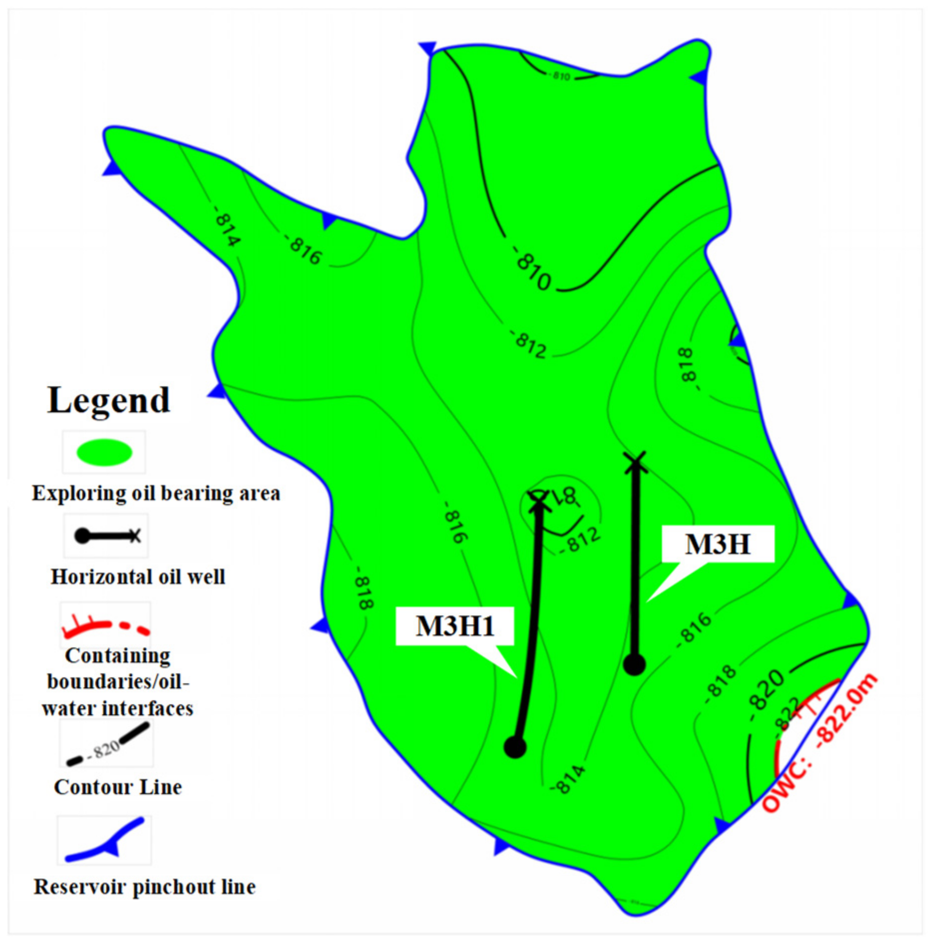
| M3H/M3H1 | 7 September 2013 | 5.75 | 16 April 2019 | 1.56 | 28 March 2021 | 4.76 | 12.07 |
| Subtotal | 15.80 | 5.45 | 4.76 | 28.95 | |||
Disclaimer/Publisher’s Note: The statements, opinions and data contained in all publications are solely those of the individual author(s) and contributor(s) and not of MDPI and/or the editor(s). MDPI and/or the editor(s) disclaim responsibility for any injury to people or property resulting from any ideas, methods, instructions or products referred to in the content. |
© 2024 by the authors. Licensee MDPI, Basel, Switzerland. This article is an open access article distributed under the terms and conditions of the Creative Commons Attribution (CC BY) license (https://creativecommons.org/licenses/by/4.0/).
Share and Cite
Zhang, D.; Li, F.; Li, Y.; Zheng, X.; Liu, C.; Liu, H.; Wang, X. Research and Application for Alternate Production Technology of Dual-Branch Horizontal Wells in an Offshore Oilfield. Processes 2024, 12, 1753. https://doi.org/10.3390/pr12081753
Zhang D, Li F, Li Y, Zheng X, Liu C, Liu H, Wang X. Research and Application for Alternate Production Technology of Dual-Branch Horizontal Wells in an Offshore Oilfield. Processes. 2024; 12(8):1753. https://doi.org/10.3390/pr12081753
Chicago/Turabian StyleZhang, Dong, Fenghui Li, Yanlai Li, Xu Zheng, Chunyan Liu, Hongjie Liu, and Xiang Wang. 2024. "Research and Application for Alternate Production Technology of Dual-Branch Horizontal Wells in an Offshore Oilfield" Processes 12, no. 8: 1753. https://doi.org/10.3390/pr12081753
APA StyleZhang, D., Li, F., Li, Y., Zheng, X., Liu, C., Liu, H., & Wang, X. (2024). Research and Application for Alternate Production Technology of Dual-Branch Horizontal Wells in an Offshore Oilfield. Processes, 12(8), 1753. https://doi.org/10.3390/pr12081753