Article

Wellbore Temperature Prediction Model and Influence Law of Ultra-Deep Wells in Shunbei Field, China

1
Petroleum Engineering Technology Research Institute, Sinopec Northwest Oilfield Company, Urumqi 830011, China
2
Key Laboratory of Enhanced Recovery for Fracture-Cave Oil Reservoir, Sinopec, Urumqi 830011, China
3
College of Petroleum Engineering, China University of Petroleum (Beijing), Beijing 102249, China
4
School of Energy Resources, China University of Geosciences (Beijing), Beijing 100083, China
5
College of Carbon Neutral Energy, China University of Petroleum (Beijing), Beijing 102249, China
*
Author to whom correspondence should be addressed.
Processes 2024, 12(8), 1715; https://doi.org/10.3390/pr12081715
Submission received: 6 July 2024 / Revised: 31 July 2024 / Accepted: 9 August 2024 / Published: 15 August 2024
(This article belongs to the Special Issue Modeling, Control, and Optimization of Drilling Techniques)

Abstract

:
The reservoir in the Shunbei field is characterized by ultra-deep, ultra-high temperature, and ultra-high pressure. During the drilling process, the circulating temperature at the bottom of the well is higher than the temperature resistance of downhole instruments, which leads to frequent problems of device burnout and no signal. Therefore, it is of great significance to accurately predict the wellbore temperature field of ultra-deep directional wells. In this paper, the influence of the drilling string assembly, the flow channel structure and the flow pattern on the convective heat exchange coefficient is considered. Based on the energy conservation equation, a numerical model of wellbore-formation transient heat transfer is developed. Then, the model was verified by the real data of two ultra-deep wells in Shunbei block, China, and the results showed that the prediction errors of bottom-hole temperature were all within 2%. Finally, the key factors and rules of the wellbore annulus temperature are analyzed. The results show that the bottom-hole temperature decreases with the decrease of inlet temperature, the thermal conductivity of drilling fluid, and the thermal conductivity of drill pipe, and increases with the decrease of flow rate, the density of drilling fluid, viscosity of drilling fluid, and specific heat capacity of drilling fluid. The inlet temperature has the greatest influence on the outlet temperature, and the specific heat of the pipe string has a minor influence on the wellbore annulus temperature. The research results of this paper provide an accurate wellbore temperature field prediction method for ultra-deep directional wells in the Shunbei block, China, which is of great significance for temperature-controlled drilling.

1. Introduction

Shunbei block of Northwest Oilfield is the base of SINOPEC’s “Deep Earth Project”, and four big oil and gas fields have been implemented, which is the main position for increasing storage and production [1]. The average depth of oil and gas reservoir is more than 7300 m, and the reservoir type is mainly carbonate fracture-cave type, which is characterized by ultra-deep, ultra-high temperature, ultra-high pressure, and ultra-high gas-oil ratio and faced with many world-class problems such as complex geological structure, crushing and easy to collapse, and directional difficulties during drilling [2,3]. Among them, due to the high-temperature environment, the bottomhole temperature (BHT) of some wells exceeds 200 °C, while the temperature resistance of the existing downhole temperature measurement instruments is around 175 °C. When the bottom-hole circulation temperature (BHCT) exceeds the temperature limit of the downhole instruments, it is very easy to lose the signal of the instruments or even burnt out the chip and precision devices, which seriously affects the directional construction of the ultra-deep wells and the measurements of the important reservoir parameters [4,5]. Therefore, it is of great significance to accurately predict the wellbore temperature and clarify its main influence factors for temperature control drilling.
For the prediction of wellbore temperature field in ultra-deep wells, extensive research has been carried out, mainly based on the API empirical method, analytical method [6,7], and numerical method [8,9,10,11]. Among them, the prediction of the BHCT based on the API empirical method leads to higher predicted results than the measured temperatures due to the lack of a correct understanding of the complex wellbore-formation heat exchange process [12]. The analytical method usually treats the wellbore as a one-dimensional steady-state temperature field, while the temperature distribution of the well wall is transient, with more assumptions leading to certain limitations. Holmes–Swift [13] established an analytical model to predict the bottom-hole temperature based on Raymond’s steady-state model [14]; the maximum relative error is 4.6%, but it is only applicable to the calculation of the wellbore temperature with a longer circulation time. Hasan–Kabir [15] developed an analytical model of the drill pipe, annulus and formation temperature under positive and negative circulation conditions based on the Holmes–Swift model [13]. In order to comprehensively consider more influencing factors and obtain more accurate prediction results, numerical methods are mostly used to predict the wellbore temperature. Marshall–Bentsen [16] established a mathematical model of the wellbore temperature distribution during drilling and cementing operations. Shiming [17,18] developed a two-dimensional transient mathematical model of the formation during circulation and compiled a wellbore temperature distribution software applied to cementing operation conditions; the maximum relative error is −3.58%. Bing [19] conducted a systematic sensitivity analysis of the many factors affecting the wellbore temperature. Abdelhafiz [20] considered the effect of both laminar and turbulent flow patterns on convective heat transfer and constructed a transient numerical and analytical model for heat transfer in the wellbore. Youzhi et al. [21] established a wellbore transient temperature calculation model based on the actual conditions of wells in the western Sichuan basin. Xiangyang et al. [22] established a numerical model of wellbore-formation heat transfer during drilling fluid circulation and an analytical model of wellbore-formation heat transfer based on the principle of energy conservation of differential unit, and the results showed that the numerical model has higher prediction accuracy. However, due to the complex structure of tubular columns in ultra-deep directional wells, which leads to variable shapes of drilling fluid flow paths and more complicated flow heat transfer, it is difficult to accurately predict the wellbore temperature field of ultra-deep directional wells in Shunbei block by the above wellbore temperature field prediction methods.
In order to more accurately predict the wellbore temperature of ultra-deep directional wells in the Shunbei block, this paper considers the influence of the drilling string assembly, flow channel structure and flow pattern on convective heat transfer coefficient and establishes a one-dimensional wellbore and two-dimensional formation wellbore-formation transient heat transfer model. Then employs two actual wells in the Shunbei block to validate the predictive effect of the model and assess its applicability in ultra-deep directional wells in the Shunbei block. Finally, the inlet temperature (ILT), the flow rate of circulation, rheology and thermophysical properties of drilling fluid, and thermophysical properties of drill pipe on wellbore temperature are analyzed, which will provide a reference for the design of temperature control programs for ultra-deep directional wells in the Shunbei block.

2. Model Development
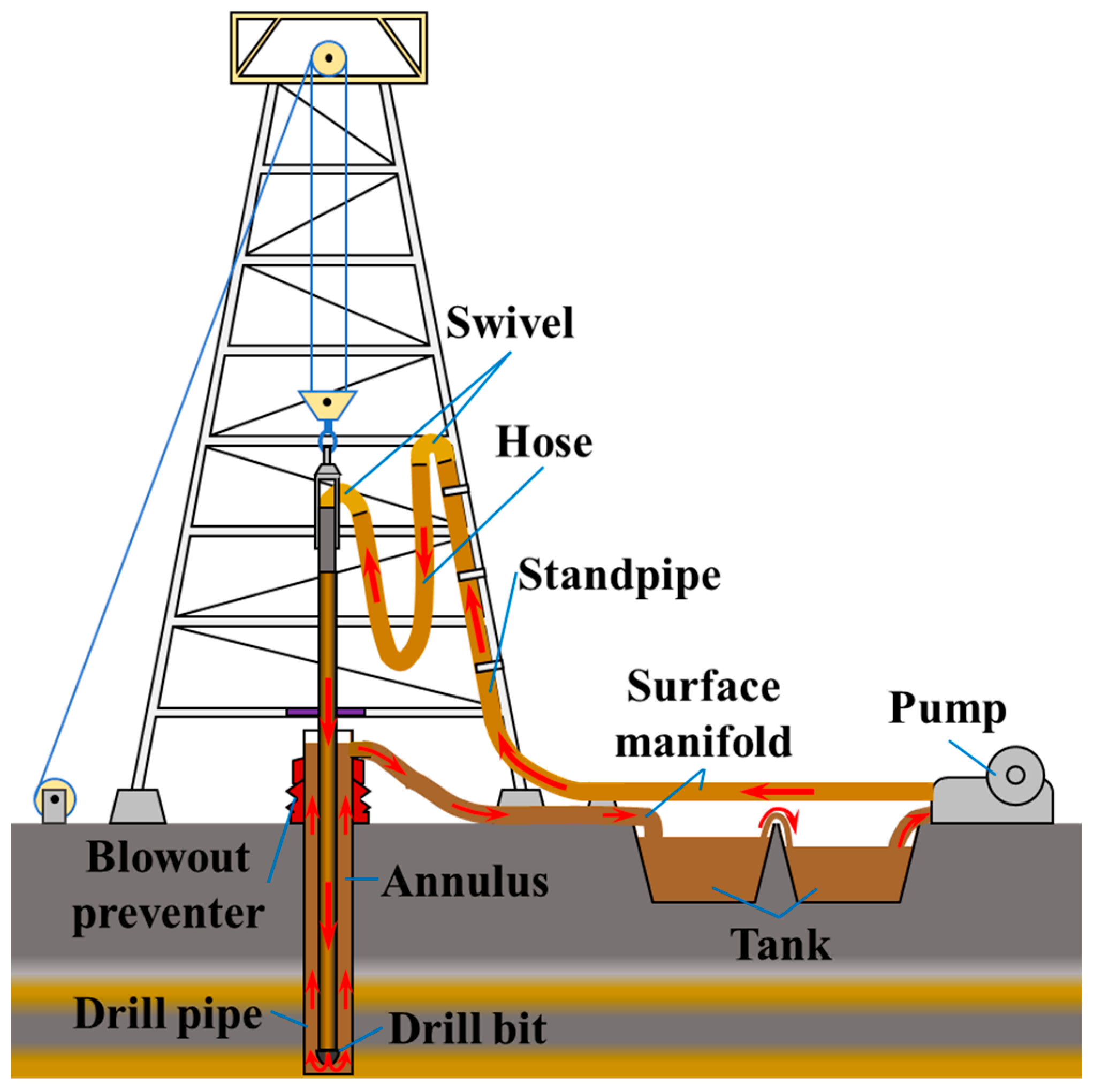
2.1. Physical Model

In the process of drilling and rock-breaking, the circulation of drilling fluid can be divided into two stages, as shown in Figure 1. First, the drilling fluid is injected from the wellhead into the drill pipe and flows downward to the drill bit. During the downward flow of drilling fluid, convective heat transfer is carried out with the drill pipe, which heats up the drilling fluid in the drill pipe, and due to the existence of the temperature gradient, it leads to the heat conduction of the drilling fluid itself. Second, the drilling fluid flows out through the bit nozzle and then enters the wellbore annulus to flow upward and return to the wellhead. In the process of returning upwards, the drilling fluid carries out convective heat transfer with the well wall and casing, which heats the drilling fluid in the annulus. The drilling fluid in the annulus also convectively exchanges heat with the drill pipe and heats the drill pipe, while the drilling fluid itself conducts heat due to the existence of a temperature gradient.

2.2. Basic Assumption

Based on the heat transfer process between the wellbore and the formation during the circulating drilling process of ultra-deep directional wells and the circulation characteristics of the drilling fluid in the drill pipe and in the annulus, the following basic assumptions are made for the established model.
  • Only radial heat conduction and convective heat transfer between the fluid and the solid are considered [23].
  • The drilling fluid in the drill pipe and annulus is a single-phase incompressible fluid, and the effects of temperature and pressure on its thermophysical properties and rheology are neglected [16,17,18].
  • The borehole trajectory and wall shape are regular, and there is no flexing or eccentricity of the drill pipe throughout the well section.
  • At a certain distance from the well wall, the formation temperature is not affected by the heat transfer from the wellbore and is the static formation temperature [23].
  • There is no internal heat source within the formation, and the formation is homogeneous [17,18].

2.3. Mathematical Model

The heat transfer process between the fluid and the formation during the drilling process of ultra-deep directional wells mainly consists of two heat transfer forms, including heat conduction and heat convection. A micro-unit is taken along the axis of the borehole at the depth z and the time t, as shown in Figure 2. And the mathematical models for the heat transfer of the drilling fluid in the drill pipe, the drill pipe wall, the drilling fluid in the annulus, the casing, the cement and the formation are established based on the energy conservation equation.
(1)
Heat transfer model of drilling fluids in drill pipe
The heat of the drilling fluid micro-unit in the drill pipe is mainly composed of 3 parts: (a) The change of internal energy of the drilling fluid inside the drill pipe. (b) Heat is carried by the downward flow of drilling fluid. (c) Heat from convective heat transfer between the drilling fluid and the wall of the drill pipe [24]. It is mathematically expressed as follows:
ρ d C d π r p , i 2 T d t = ρ d V d π r p , i 2 C d T d z + 2 π r p , i h d - p T p T d
where ρd is the density of drilling fluid, kg/m3. Cd is the specific heat capacity of drilling fluid, J/kg/°C. rp,i is the inner diameter of the drill pipe, m. Td is the temperature of drilling fluid in the drill pipe, °C. t is the time, s. Vd is the flow rate of the drilling fluid in the drill pipe, m/s. z is the depth, m. hd-p is the convective heat transfer coefficient of the wall of the drill pipe, W/m2/°C. Tp is the temperature of the wall of the drill pipe, °C.
(2)
Heat transfer model of drill pipe wall
The temperature of the drill pipe wall is closely related to the flow of drilling fluid inside the drill pipe and the annulus, and the heat of its micro-unit mainly consists of four parts: (a) The change of internal energy of the drill pipe wall. (b) Heat gained by heat transfer from the drill pipe wall in the axial direction. (c) Heat gained by convective heat transfer between the drill pipe wall and the drilling fluid inside the drill pipe. (d) The heat of convective heat transfer between the drill pipe wall and drilling fluid in the annulus [24]. The specific mathematical expressions are shown as follows:
ρ p C p π r p , o 2 r p , i 2 T p t = λ p π r p , o 2 r p , i 2 2 T p z 2 + 2 π r p , i h d - p T d T p + 2 π r p , o h p - a T a T p
where ρp is the density of the drill pipe wall, kg/m3. Cp is the specific heat capacity of the drill pipe, J/kg/°C. rp,o is the outer diameter of the drill pipe, m. λp is the thermal conductivity of the drill pipe, W/m/°C. hp-a is the convective heat transfer coefficient between the drilling fluid in the annulus and the drill pipe, W/m2/°C. Ta is the temperature of the drilling fluid in the annulus, °C.
(3)
Heat transfer model of drilling fluids in the annulus
The temperature of the drilling fluid in the annulus is mainly affected by the following four aspects: (a) The change in the internal energy of the drilling fluid itself in the annulus. (b) The heat carried by the drilling fluid flowing upward in the annulus. (c) The heat generated by convective heat transfer between the drilling fluid in the annulus and the outer wall of the drilling column. (d) The heat of convective heat transfer between the drilling fluid in the annulus and the inner wall of the casing or the formation [24]. It can be expressed as follows:
ρ d C d π r ca 1 , i 2 r p , o 2 T a t = ρ d V a π r ca 1 , i 2 r p , o 2 C d T a z + 2 π r p , o h p - a T p T a + 2 π r ca 1 , i h a - c T ca 1 T a
where rca1,i is the inner diameter of the first casing or the diameter of the borehole, m. Va is the velocity of the drilling fluid in the annulus, m/s. ha-c is the convective heat transfer coefficient between the drilling fluid in the annulus and the casing or the borehole wall, W/m2/°C. Tca1 is the temperature of the first casing or the borehole wall, °C.
(4)
Heat transfer model of casing
The temperature distribution of the first layer of casing from inside to outside centered on the wellbore is mainly affected by the following 4 factors: (a) The change in internal energy of the casing itself. (b) Heat conduction in the axial direction. (c) Heat from convective heat transfer between the casing and the annulus drilling fluid. (d) Heat conduction between the casing and the first layer of cemented annulus [25]. The specific expression of the heat transfer mathematical model of the casing is as follows:
ρ ca C ca π r ca 1 , o 2 r ca 1 , i 2 T ca 1 t = λ ca π r ca 1 , o 2 r ca 1 , i 2 2 T ca 1 z 2 + 2 π r ca 1 , i h a - c T a T ca 1 + 2 π r ca 1 , o λ ca 1 - ce 1 T ce 1 T ca 1 r ca 2 , i r ca 1 , i / 2
where ρca is the density of the casing, kg/m3. Cca is the specific heat capacity of the casing, J/kg/°C. rca1,o is the outer diameter of the first casing, m. λca is the thermal conductivity of the casing, W/m/°C. rca2,i is the inner diameter of the second layer of casing, m. Tce is the temperature of the first layer of cement, °C. λca1-ce1 is the combined thermal conductivity between the first layer of the casing and the first layer of cement, W/m/°C, which can be expressed as
λ ca 1 - c e 1 = r ca 2 , i r ca 1 , i r ca 2 , i r ca 1 , o λ ce + r ca 1 , o r ca 1 , i λ ca
(5)
Heat transfer model of cement
The temperature distribution of the first layer of cement from inside to outside centered on the wellbore is mainly affected by the following three factors: (a) The change of internal energy of the cement ring itself. (b) The heat conduction formed in the axial direction due to the presence of a temperature gradient. (c) The heat conduction generated by the cement and the second layer of casing [25,26,27]. The specific expression of the mathematical model is as follows:
ρ ce C ce π r ca 2 , i 2 r ca 1 , o 2 T ce 1 t = λ ce π r ca 2 , i 2 r ca 1 , o 2 2 T ce 1 z 2 + 2 π r ca 2 , i λ ce 1 - ca 2 T ca 2 T ce 1 r ca 2 , o r ca 1 , o / 2
where ρce is the density of the cement, kg/m3. Cce is the specific heat capacity of the cement, J/kg/°C. λce is the thermal conductivity of the cement, W/m/°C. rca2,o is the outer diameter of the second layer of casing, m. Tca2 is the temperature of the second layer of casing °C. λce1-ca2 is the combined thermal conductivity between the first layer of cement and the second layer of the casing, W/m/°C, which can be expressed as
λ ce 1 - ca 2 = r ca 2 , o r ca 1 , o r ca 2 , o r ca 2 , i λ ca + r ca 2 , i r ca 1 , o λ ce
(6)
Heat transfer model of the formation
After the last layer of casing from inside to outside (i.e., the surface casing), all of them are formation rocks, and there is only axial and radial heat transfer within the formation layer, and it can be regarded as heat conduction in the wall of a single cylinder [25]. The expression for the mathematical model of formation heat transfer is
ρ f C f T f t = λ f 2 T f z 2 + λ f r r r T f r
where ρf is the density of the formation, kg/m3. Cf is the specific heat capacity of the formation, J/kg/°C. Tf is the temperature of the formation, °C. λf is the thermal conductivity of the formation, W/m/°C. r is the radius of the formation, m.

2.4. Convective Heat Transfer Coefficient

The convective heat transfer coefficient is usually calculated using the Nusselt number with the following expression:
h = N u λ D h
where h is the convective heat transfer coefficient, W/m2/°C. Nu is the Nusselt number. λ is the thermal conductivity, W/m/°C. Dh is the inner diameter of the pipe or the annulus hydrodynamic diameter, m.
For laminar flow in a circular tube or annulus, Incropera et al. [28] gave an analytical solution for the Nusselt number in two cases: 4.36 when the boundary is a constant wall heat flux and 3.66 when the boundary is a constant wall temperature.
For circular tube turbulence, Gnielinski [29] proposed a Nusselt number calculation method as follows:
N u p = f p / 8 R e p 1000 P r p 1 + 12.7 f p / 8 0.5 P r p 2 / 3 1
where Rep is the Reynolds number of turbulence in the circular tube. Prp is the Prandtl number. fp is the friction factor, which is calculated as follows:
f p = 1.82 log R e p 1.64
Gnielinski [30] modified the circular pipe turbulence model for circumpolar turbulence and obtained a method for calculating the Nussle number for circumpolar turbulence:
N u a = f a 8 R e a P r a 1 + D h L 2 / 3 F a k 1 + 12.7 f a 8 0.5 P r a 2 / 3 1
where Rea is the Reynolds number of turbulence in the circular tube. Pra is the Prandtl number. fa is the friction factor. Dh is the hydraulic diameter of the annulus, m. L is the length of the annulus, m. fa is the correction factor.
D h = 2 r o r i
k 1 = 1.07 + 900 R e 0.63 1 + 10 P r
f a = 1 1.8 log R e * 1.5 2
R e * = R e 1 + η ln η + 1 η 2 1 η 2 ln η
F a = 0.75 η 0.17 ,     η = r i r o
where η is the gap ratio annulus. ro is the outer radius of the annulus space, m. ri is the inner radius of the annulus space, m.

2.5. Initial and Boundary Conditions

The initial and boundary conditions of the corresponding solutions need to be given, and the heat transfer mathematical model for each region is solved associatively to obtain the drilling fluid and formation temperature distribution in the wellbore [31].
(1)
Initial condition
When the drilling fluid stops circulating, the drilling fluid in the drill pipe, the drill pipe wall, the drilling fluid in the annulus, the casing and the cement will all gradually recover to the static formation temperature (SFT) and reach a steady state, so the SFT is taken as the initial temperature of each region.
T d z , t = 0 = T p z , t = 0 = T a z , t = 0 = T c z , t = 0 = T ce z , t = 0 = T f z = T s + G f z
where Ts is the temperature of the surface, °C. Gf is the temperature gradient of the stratum, °C/m.
(2)
Boundary conditions
The ILT of the drilling fluid in the drill pipe and the outlet temperature (OLT) of the drilling fluid in the annulus can be measured in real-time by instrumentation on site, so the boundary conditions at the wellhead are
T d z = 0 , t = T in T a z = 0 , t = T out
where Tin is the ILT of drilling fluid in the drill pipe, °C. Tout is the OLT of drilling fluid in the wellbore annulus, °C.
Since the heat generated by the drilling fluid flowing through the drill bit is neglected, it can be assumed that the temperature of the drilling fluid inside the drill pipe, the drill pipe wall, and the drilling fluid inside the annulus are all equal at the bottom of the well. The expression is as follows:
T d z = L , t = T p z = L , t = T a z = L , t
where L is the well depth, m.
Away from the wellbore, there is no temperature gradient within the formation in the radial direction, so it can be assumed that the SFT away from the wellbore is undisturbed and is always the SFT, with the following expression:
T f r , z , t r r = 0

3. Model Solution and Validation

3.1. Model Solution

The heat transfer equations for the drilling fluid in the drill pipe, the drill pipe wall, the drilling fluid in the annulus, the casing, the cement, and the formation are linked. The pairs are discretized using the finite difference method (FDM). The control equations for each region can be written in the following general format after discretization:
A i , j n t T i , j n t + B i , j n t T i , j 1 n t + C i , j n t T i , j + 1 n t + D i , j n t T i 1 , j n t + E i , j n t T i + 1 , j n t = F i , j n t T i , j n t 1
where A, B, C, D, E, and F are the coefficients of the control equations of the unit control body. nt is the time node. i is the spatial node in the radial direction of the wellbore. j is the space node on the axial direction of the wellbore.
The control equations of all regions are expressed in matrix form. And combined with initial and boundary conditions and solved by the Gauss–Seidel iterative method, which can find out the temperature of each unit control body at different moments and depths.

3.2. Application Cases of Shunbei Block

In order to verify the accuracy and reliability of the wellbore-formation transient heat transfer model developed in this paper under the actual well structure conditions of ultra-deep directional wells, the model was validated with the measured circulating temperatures at the bottom of two ultra-deep directional wells, SHB X Well and SHB Y Well.
(1)
SHB X Well
SHB X Well is an exploratory well in Tarim Basin, and the main drilling purpose is to exploit reservoirs. The actual drilling depth is 8**9 m, the vertical depth is 8**5 m, and the bushing elevation is 10.5 m. When drilling the 8**2 m–8**9 m section in the 27th trip, the main lithology encountered in the well is limestone, and the BHT measured by the measurement while drilling (MWD) instrument after 47 h of circulation is 154 °C. The actual casing program of the X well structure and the borehole expansion rate of the well are shown in Table 1.
The detailed drilling tool assemblies used for the 27th trip are as follows: Φ165.1 mm PDC bit + Φ130 mm positive displacement motor + Φ121 mm non-magnetic drill collar + Φ88.9 mm drill pipe + Φ88.9 mm weighted drill pipe + Φ88.9 mm drill pipe + Φ140 mm DS400 × DS401 + Φ140 mm DS400 × DS401 + Φ139.7 mm short drill pipe. The thermal properties of heat transfer media, such as drilling fluid, drill pipe, casing, cement and formation, are shown in Table 2.
When drilling the 8**2 m−8**9 m well section, the viscosity of the drilling fluid is 20 mPa·s, the drilling fluid flow rate is 14 L/s, and the ILT of the drilling fluid is 41.3 °C and the OLT is 42.6 °C. Considering the influence of actual well structure, drilling tool combination and average well diameter expansion rate, and taking the logging temperature after stopping circulation as the original formation temperature. The prediction model of the wellbore circulating temperature field of SHB X well is constructed, and its prediction results are shown in Figure 3.
As can be seen from Figure 3, the prediction result of this model for the BHT of SHB X well is 156.08 °C, with a relative error of 1.35% and an absolute error of 2.08 °C. The prediction result for the OLT is 42.14 °C, with a relative error of 1.08% and an absolute error of 0.46 °C. The prediction result is consistent with the measured value, and the error value of both is within 2 °C, which meets the requirement of error within 10% in engineering and verifies the validity and reliability of the wellbore-formation transient temperature field prediction model established in this paper.
(2)
SHB Y Well
SHB Y well is an exploratory well in the Shuntogole Low Rise of the Tarim Basin, and the main drilling purpose is to explore the reservoir in the Ordovician. The actual drilling depth is 8**7 m, vertical depth is 7**4 m. When drilling the 8**8 m−8**4 m section in the 20th trip, the main lithology encountered in the well is limestone, and the BHT at 8230 m is 175 °C as measured by the MWD after 23 h of normal circulation. The actual well structure and borehole expansion rate of the well are shown in Table 3.
The detailed drilling tool assembly used for the 7th trip of the four openings (20th trip in total) is Φ149.2 mm PDC drill bit + Φ121 mm non-magnetic drill collar + Φ101.6 mm drill pipe + Φ88.9 mm weighted drill pipe + Φ101.6 mm drill pipe + Φ88.9 mm weighted drill pipe + Φ101.6 mm drill pipe + Φ139.7 mm drill pipe. The thermal properties of heat transfer media, such as drilling fluid, drill pipe, casing, cement, and formation, are shown in Table 4.
When drilling the 8**8 m−8**4 m well section, the viscosity of the drilling fluid is 22 mPa·s, the flow rate of the drilling fluid is 15 L/s, and the ILT of the drilling fluid is 44 °C and the OLT is 47 °C. Considering the influence of the actual casing program, drilling tool assemblies and average well diameter expansion rate, and taking the logging temperature after stopping circulation as the original formation temperature. The prediction model of the wellbore downhole circulation temperature field of the SHB Y well is constructed, and its prediction results are shown in Figure 4.
As can be seen in Figure 4, the prediction result of this model for the BHT of the SHB Y well is 176.93 °C, with a relative error of 1.1% and an absolute error of 1.93 °C. The prediction result for the OLT is 44.23 °C, with a relative error of 5.89% and an absolute error of 2.77 °C. The prediction results are more consistent with the measured values and meet the engineering requirement of error within 10%, which further verifies the validity and reliability of the wellbore-formation transient temperature field prediction model established in this paper.

4. Impact Factors and Regularities Analysis

4.1. Inlet Temperature
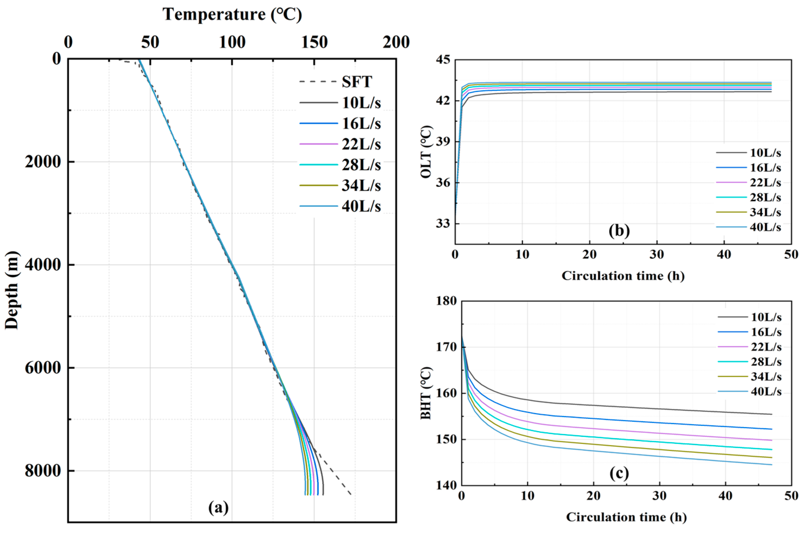
Taking the SHB X well as an example, when the drilling fluid flow rate is 14 L/s, the circulation time is 47 h, the density of the drilling fluid is 1110 kg/m3, the viscosity of the drilling fluid is 20 mPa·s, the thermal conductivity of the drilling fluid is 1.2 W/m/°C, the specific heat capacity of the drilling fluid is 1600 J/kg/°C, the thermal conductivity of the drill pipe is 48 W/m/°C, and the specific heat capacity of the drill pipe is 500 J/kg/°C, the variation of the annulus temperature profile with different ILT is shown in Figure 5.
As can be seen from Figure 5, with the increase of the ILT, the annulus OLT increases continuously. In the well depth of 0–2000 m, the influence of the ILT increase on the annulus temperature decreases gradually. When the well depth is between 2000–7000 m, the ILT has no effect on the annulus temperature. When the well depth is greater than 7000 m, the ILT increases, the BHT increases slightly, and the BHT changes less compared with the OLT. Near the wellhead, the drilling fluid with constant temperature is injected into the drill pipe, and the drilling fluid inside the drill pipe is slowly heated; the temperature difference between the annulus drilling fluid and the drill pipe and the drilling fluid inside the drill pipe becomes larger after sufficient heat exchange with the formation at the wellhead, and the heat exchange is further strengthened, so the temperature of the drilling fluid at the wellhead is controlled by the ILT. When the depth of the well is greater than 2000 m, the formation temperature is always higher than the drilling fluid temperature in the wellbore and continues to heat the drilling fluid. The drilling fluid temperature in the wellbore is mainly affected by the formation temperature, so the ILT has less influence.

4.2. Flow Rate

When the drilling fluid ILT is 41.3 °C, the circulation time is 47 h, the density of the drilling fluid is 1110 kg/m3, the drilling fluid viscosity is 20 mPa·s, the thermal conductivity of the drilling fluid is 1.2 W/m/°C, the specific heat capacity of the drilling fluid is 1600 J/kg/°C, the thermal conductivity of the drill pipe is 48 W/m/°C, and the specific heat of the drill pipe is 500 J/kg/°C, the annulus temperature profiles with different circulation flow rate is shown in Figure 6.
As can be seen from Figure 6, with the increase of drilling fluid circulation flow rate, the annulus temperature below the well depth of 7000 m gradually decreases. At the same time, the annulus temperature above the well depth of 7000 m remains unchanged. With the same circulation time, the larger the drilling fluid flow rate is, the more heat is absorbed by the annulus drilling fluid from the formation, and then the formation temperature in the near-well area is lower. As the circulation continues, the temperature difference decreases, the heat exchange between the drilling fluid and the well wall is weakened, and the temperature of the bottom annulus is lower. In addition, the more heat the annular drilling fluid carries from the bottom hole to the wellhead, the higher the OLT.

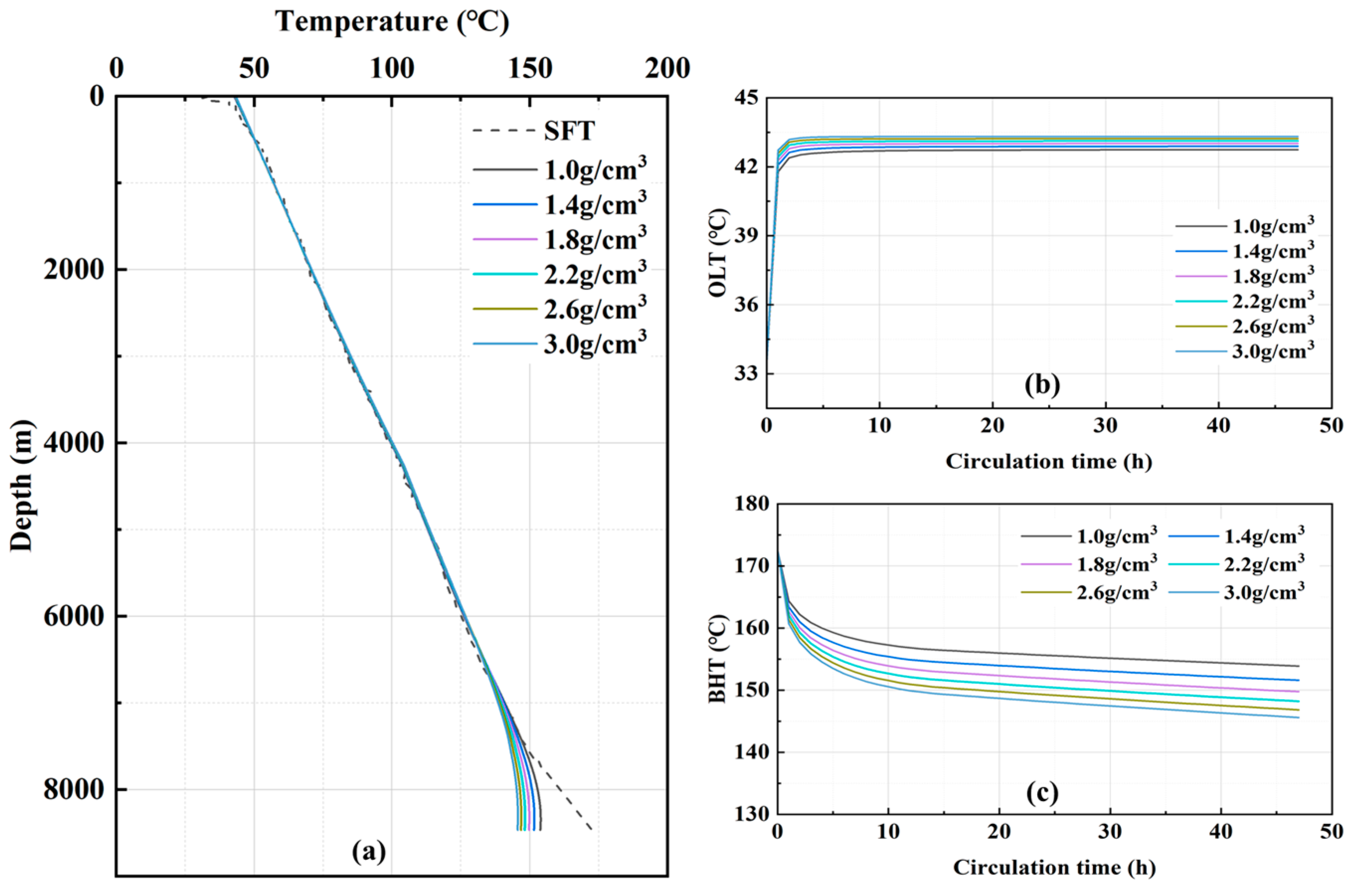
4.3. Drilling Fluid Properties

(1)
Density of the drilling fluid
The drilling fluid ILT is 41.3 °C, the circulation flow rate is 14 L/s, the circulation time is 47 h, the drilling fluid viscosity is 20 mPa·s, the drilling fluid thermal conductivity is 1.2 W/m/°C, the drilling fluid specific heat capacity is 1600 J/kg/°C, the drill pipe thermal conductivity is 48 W/m/°C, and the drill pipe specific heat capacity is 500 J/kg/°C. The variation of the annulus temperature profile with different drilling fluid densities is shown in Figure 7.
As can be seen from Figure 7, with the increase of drilling fluid density, the annulus temperature near the bottom hole below the depth of 6500 m decreases gradually. And the annular temperature of the well section above 6500 m in well depth remains unchanged. Under the same circulation time, the higher the drilling fluid density, the more heat the annulus drilling fluid carries from the formation, then the lower the formation temperature. As the circulation continues, the weaker the heat exchange between the drilling fluid and the well wall occurs, and the lower the annulus temperature in the bottom section of the well. In addition, as the annulus drilling fluid carries more heat from the bottom hole to the wellhead, the OLT becomes larger.
(2)
Viscosity of the drilling fluid
When the drilling fluid ILT is 41.3 °C, the flow rate of circulation is 14 L/s, the circulation time is 47 h, the density of the drilling fluid is 1110 kg/m3, the thermal conductivity of the drilling fluid is 1.2 W/m/°C, the specific heat capacity of the drilling fluid is 1600 J/kg/°C, the thermal conductivity of the drill pipe is 48 W/m/°C, and the specific heat capacity of the drill pipe is 500 J/kg/°C, the variation of annulus temperature profile with different drilling fluid viscosities is shown in Figure 8.
As can be seen from Figure 8, with the increase of drilling fluid viscosity, the annular temperature near the bottom hole below 7000 m depth decreases gradually. And the annular temperature of the well section above 7000 m depth is not affected by the change of viscosity. Under the same circulation time, the greater the viscosity of the drilling fluid, the greater the convective heat transfer coefficient, and the more heat the annulus drilling fluid carries from the formation in the lower section of the well, the lower the formation temperature. As the circulation continues, the heat exchange between the drilling fluid and the well wall is weakened, and the temperature of the annular drilling fluid in the bottom well section is lower. In addition, due to the increase in heat carried by the annular drilling fluid in the process of returning from the bottom of the well to the wellhead, the OLT will become larger.
(3)
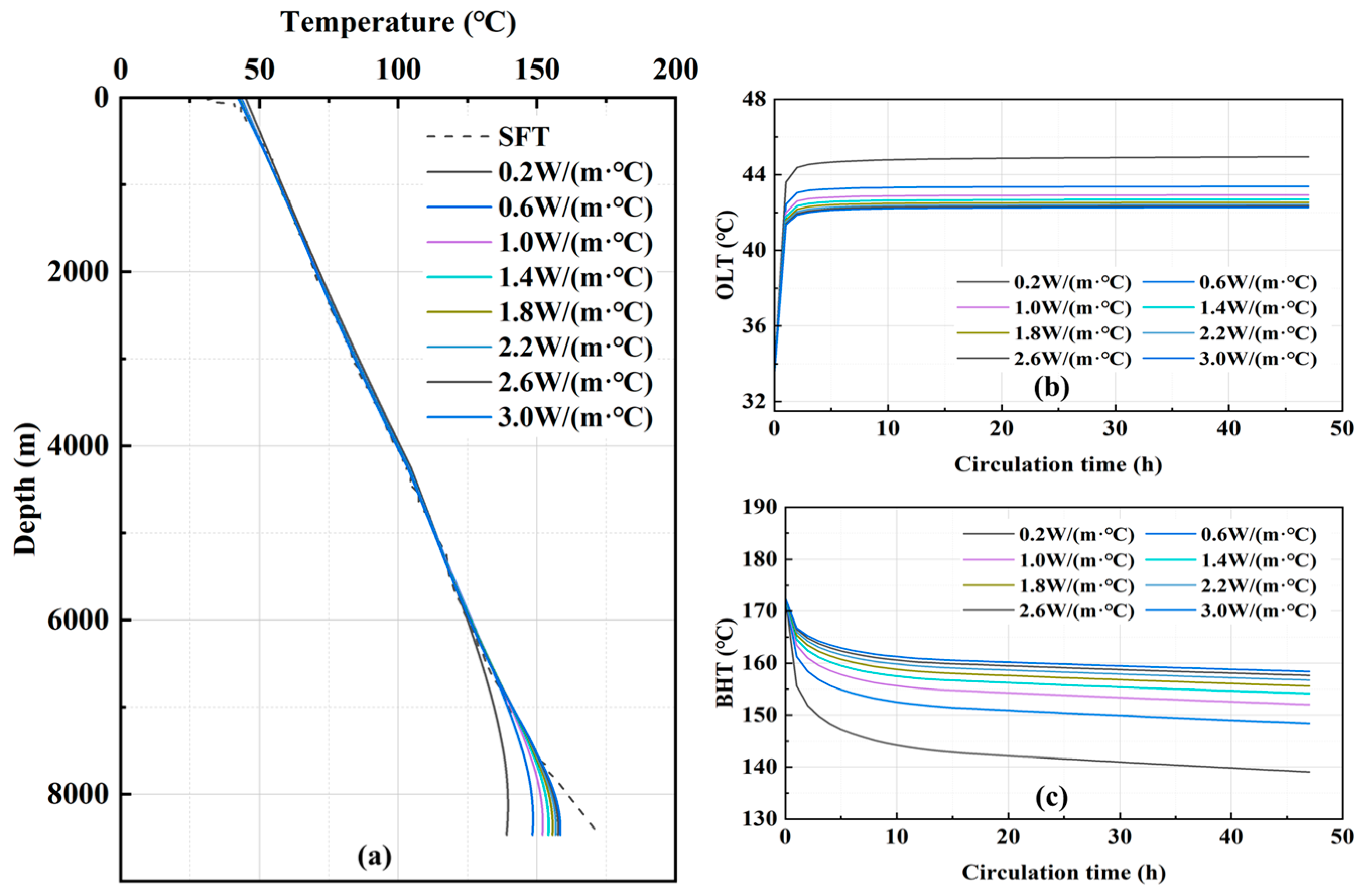
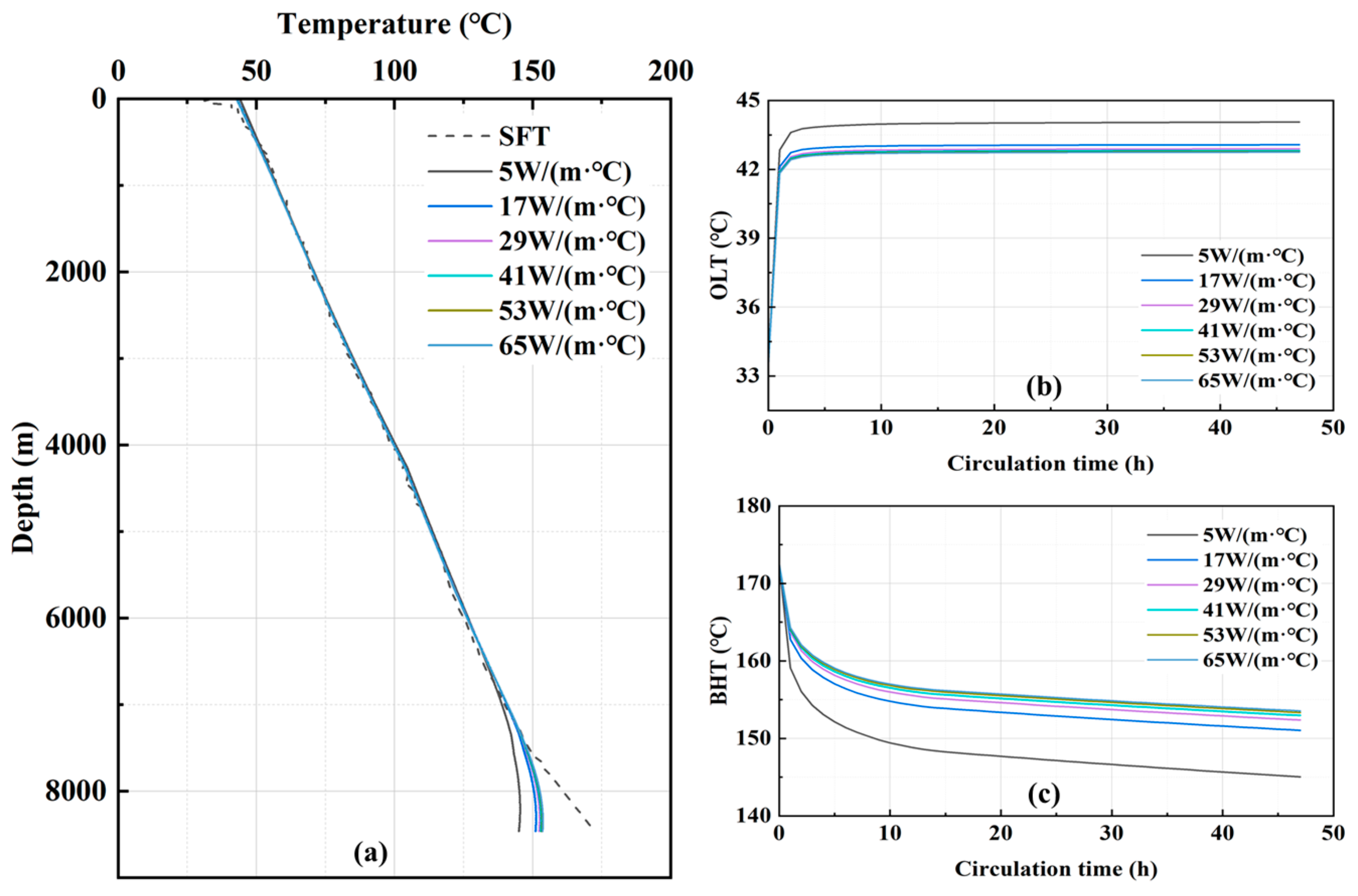
Thermal conductivity of the drilling fluid
When the drilling fluid ILT is 41.3 °C, the circulation flow rate is 14 L/s, the circulation time is 47 h, the density of the drilling fluid is 1110 kg/m3, the viscosity of the drilling fluid is 20 mPa·s, the specific heat capacity of the drilling fluid is 1600 J/kg/°C, the thermal conductivity of the drill pipe is 48 W/m/°C, and the specific heat capacity of the drill pipe is 500 J/kg/°C, the annulus temperature profiles with different drilling fluid thermal conductivity coefficients are shown in Figure 9.
As can be seen from Figure 9, with the increase of thermal conductivity of drilling fluid, the annulus temperature near the bottom hole below 6000 m depth increases gradually. And the annular temperature of the upper well section above 6000 m depth is not affected by the thermal conductivity of the drilling fluid. Under the same circulation time, the larger the thermal conductivity of the drilling fluid, the larger the convective heat transfer coefficient between the drilling fluid and well wall or drill pipe, the faster the heat exchange rate, the faster its temperature rises, resulting in accelerated warming of drilling fluid in the drilling pipe in the process of downward flow, and the BHT becomes higher, and the OLT is closer to the ILT.
(4)
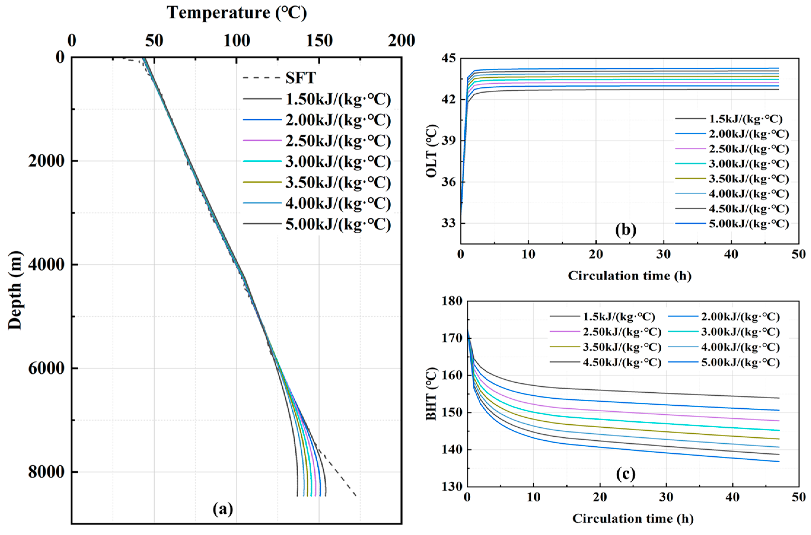
Specific heat capacity of the drilling fluid
When the drilling fluid ILT is 41.3 °C, the flow rate is 14 L/s, the circulation time is 47 h, the drilling fluid density is 1110 kg/m3, the drilling fluid viscosity is 20 mPa·s, the drilling fluid thermal conductivity is 1.2 W/m/°C, the drill pipe thermal conductivity is 48 W/m/°C, and the specific heat capacity of the drill pipe is 500 J/kg/°C, the variation of the annulus temperature profile with different drilling fluid specific heat capacity is shown in Figure 10.
As can be seen from Figure 10, with the increase of the specific heat of the drilling fluid, the annulus temperature below the well depth of 6000 m decreases gradually. And the change of annulus temperature above 6000 m well depth is not affected by the change of specific heat of drilling fluid. Under the same circulation time, the larger the specific heat of the drilling fluid is, the stronger its heat absorption ability is, and the more heat the annulus drilling fluid carries from the bottom formation, the lower the formation temperature is. As the circulation continues, the weaker the heat exchange between the drilling fluid and the well wall occurs, the lower the temperature of the annular drilling fluid. In addition, as the circulating drilling fluid carries more heat from the bottom of the well to the wellhead, the exit temperature becomes larger.

4.4. Drill Pipe Thermophysical Properties

(1)
Thermal conductivity of the drill pipe
When the drilling fluid ILT is 41.3 °C, the flow rate is 14 L/s, the circulation time is 47 h, the drilling fluid density is 1110 kg/m3, the drilling fluid viscosity is 20 mPa·s, the drilling fluid thermal conductivity is 1.2 W/m/°C, the specific heat capacity of the drilling fluid is 1600 J/kg/°C, and the specific heat capacity of the drill pipe is 500 J/kg/°C, the variation of annulus temperature profile with different drill pipe thermal conductivity is shown in Figure 11.
As can be seen from Figure 11, with the increase of the thermal conductivity of the drill pipe, the temperature of the annulus below the well depth of 7000 m gradually increases, while the temperature of the annulus in the upper well section above the well depth of 7000 m has no change. Under the same circulation time, the greater the thermal conductivity of the drill pipe, the faster the heat exchange between the drilling fluid in the annulus and the drilling fluid inside the drill pipe. The temperature of the drilling fluid inside the drill pipe keeps increasing, leading to an increase in the bottom-hole temperature. In addition, at the outlet of the annulus, due to the accelerated rate of heat exchange between the annulus drilling fluid and the inlet drilling fluid, the OLT is caused to be closer to the ILT.
(2)
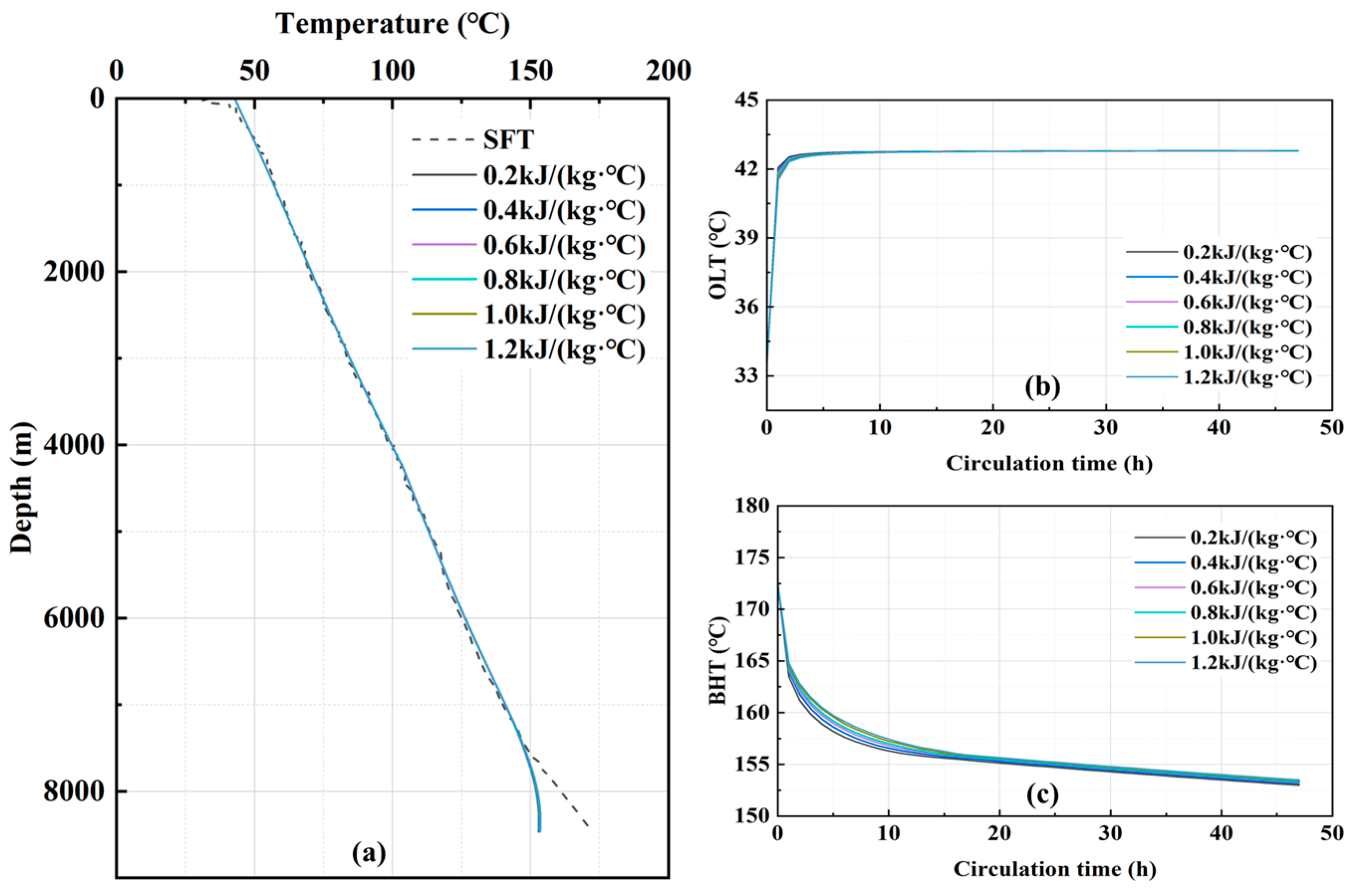
Specific heat capacity of the drill pipe
When the drilling fluid injection temperature is 41.3 °C, the displacement is 14 L/s, the circulation time is 47 h, the drilling fluid density is 1110 kg/m3, the drilling fluid viscosity is 20 mPa·s, the drilling fluid thermal conductivity is 1.2 W/m/°C, the specific heat capacity of the drilling fluid is 1600 J/kg/°C, and the tubing column thermal conductivity is 48 W/m/°C, the variation relationship of annulus temperature profile with different specific heat of tubing column is shown in Figure 12.
As can be seen from Figure 12, the wellbore annulus temperature does not change as the specific heat of the drill pipe increases. This is due to the fact that the change in the specific heat of the tubing column only affects the temperature of the tubing column itself and has no effect on the convective heat transfer coefficient, so there is no change in the annular temperature of the wellbore.

4.5. The Key Factors Impact Level

Based on the results of the above numerical calculations, the rate of change of the influencing factors such as ILT, flow rate, drilling fluid density, drilling fluid viscosity, drilling fluid thermal conductivity, specific heat of drilling fluid, thermal conductivity of drill pipe, and specific heat of drill pipe were calculated respectively, as well as the rate of change of the BHT under the corresponding conditions, and the results are shown in Figure 13.
The formula for calculating the change rate of each parameter can be expressed as below:
R c = x min x min x
where Rc is the rate of change of the parameter. x is the key impact parameter or BHT. min is the function that takes the minimum value.
As can be shown in Figure 13, specific heat of drilling fluid, flow rate, drilling fluid density, and drilling fluid viscosity have a greater effect on the BHT, and the BHT decreases with the increase of these parameters. Drilling fluid thermal conductivity and drill pipe thermal conductivity have a greater influence on the BHT when it is small, and the influence on the BHT gradually decreases with the increase of thermal conductivity, and the BHT increases with the increase of these parameters. The ILT and the specific heat of the drill pipe have little effect on the BHT. Combined with Figure 6, Figure 7, Figure 8, Figure 9, Figure 10, Figure 11, Figure 12 and Figure 13, it can be seen that flow rate, drilling fluid density, drilling fluid viscosity, drilling fluid thermal conductivity, drilling fluid specific heat and drill pipe thermal conductivity have a greater influence on the BHT, the ILT has the greatest influence on the OLT, and the drill pipe specific heat has no influence on the wellbore annulus temperature.

5. Conclusions

(1)
Based on the principle of energy conservation, a wellbore-formation transient heat transfer model with one-dimensional wellbore and two-dimensional formation has been established by considering the effects of casing program, drilling string assembly, flow channel structure and drilling fluid flow pattern on convective heat transfer coefficients;
(2)
Data from two actual wells in the Shunbei block are used to further validate the applicability and reliability of the model developed in this paper. The prediction error of BHCT in SHB X well is 1.35%, and the prediction error of OLT is 1.08%. The prediction error of BHCT of SHB Y well is 1.1%, and the prediction error of OLT is 5.89%. The results show that the model established in this paper is applicable to the prediction of wellbore temperature in ultra-deep directional wells in the Shunbei block, and the prediction error of BHT is about 2%;
(3)
The key influencing factors and laws of wellbore annular temperature were analyzed, among which the flow rate, drilling fluid density, drilling fluid viscosity, drilling fluid thermal conductivity, drilling fluid specific heat, and drill pipe thermal conductivity have a greater influence on the BHT, the ILT has the greatest influence on the OLT, while the drill pipe specific heat has no influence on the wellbore annular temperature.

Author Contributions

Conceptualization, Z.D. and X.C.; methodology, Z.D. and X.Y.; software, Z.X.; validation, Z.D., X.C. and W.Y.; formal analysis, M.Z.; investigation, X.S.; resources, X.Y.; data curation, Z.D.; writing—original draft preparation, Z.D.; writing—review and editing, X.C. and W.Y.; visualization, X.Y.; supervision, Z.X. and M.Z.; project administration, X.S.; funding acquisition, X.C. and X.S. All authors have read and agreed to the published version of the manuscript.

Funding

This research was funded by the project of Sinopec Group Corporation, “Research and Application of Heat-Insulating Technology for Drilling Tools in High-Temperature Wells”, grant number P22119.

Data Availability Statement

The data are not publicly available due to the involvement of information on Chinese oil fields and need to be kept confidential.

Conflicts of Interest

Authors Zhigang Dang, Xiuping Chen and Weixing Yang are employed by the Petroleum Engineering Technology Research Institute, Sinopec Northwest Oilfield Company. The remaining authors declare that the research was conducted in the absence of any commercial or financial relationships that could be construed as a potential conflict of interest.

References

  1. Zongqi, C.; Xianghua, L.; Binzhen, B.; Hao, Y. Technical Progress and Development Consideration of Drilling and Completion Engineering for Ultra-deep Wells in the Shunbei Oil & Gas Field. Pet. Drill. Tech. 2022, 50, 1–10. [Google Scholar]
  2. Lixin, Q.; Lu, Y.; Zicheng, C.; Haiying, L.; Cheng, H. Geological Reserves Assessment and Petroleum Exploration Targets in Shunbei Oil & Gas Field. Xinjiang Pet. Geol. 2021, 42, 127. [Google Scholar]
  3. Yongsheng, M.; Xunyu, C.; Lu, Y.; Zongjie, L.; Huili, L.; Shang, D.; Peirong, Z. Practice and Theoretical and Technical Progress in Exploration and Development of Shunbei Ultra-deep Carbonate Oil and Gas Field, Tarim Basin, NW China. Pet. Explor. Dev. 2022, 49, 1–20. [Google Scholar]
  4. Xiong, S.; Minghe, Y.; Weifeng, C.; Jun, Z. Study and Application of Wellbore Temperature Field Characteristics in the Ultra-deep Slim-hole Wells in the Shunbei No. 1 Area. Pet. Drill. Tech. 2021, 49, 67–74. [Google Scholar]
  5. Xianghua, L.; Huan, D.; Biao, L.; Hongning, Z.; Rong, S. Key Technology of Directional Drilling in the Ultra-deep High-temperature IV Belt, the Shunbei Oilfield. Oil Drill. Prod. Technol. 2022, 44, 665–670. [Google Scholar]
  6. Kabir, C.; Hasan, A.; Kouba, G.; Ameen, M. Determining Circulating Fluid Temperature in Drilling, Workover, and Well Control Operations. SPE Drill. Complet. 1996, 11, 74–79. [Google Scholar] [CrossRef]
  7. Cunxi, W.; Yingfeng, M.; Wei, J.; Hu, D. Hole Temperature Variation and Its Effects on Gas Injection Rate During Gas Drilling. Nat. Gas Ind. 2007, 27, 67. [Google Scholar]
  8. Willhite, G.P. Over-all Heat Transfer Coefficients in Steam and Hot Water Injection Wells. J. Pet. Technol. 1967, 19, 607–615. [Google Scholar] [CrossRef]
  9. Ruiyao, Z.; Jun, L.; Gonghui, L.; Hongwei, Y.; Hailong, J. Analysis of Coupled Wellbore Temperature and Pressure Calculation Model and Influence Factors under Multi-pressure System in Deep-water Drilling. Energies 2019, 12, 3533. [Google Scholar] [CrossRef]
  10. Chuanjun, H.; Wenkang, C.; Liangliang, D.; Qiang, Z. A New Two-dimensional Transient Forecast Model of Wellbore Temperature Based on Precise Time Step Integration Method. J. Pet. Sci. Eng. 2022, 215, 110708. [Google Scholar]
  11. Hongwei, Y.; Jun, L.; Hui, Z.; Jiwei, J.; Boyun, G.; Geng, Z. Numerical Analysis of Heat Transfer Rate and Wellbore Temperature Distribution under Different Circulating Modes of Reel-well Drilling. Energy 2022, 254, 124313. [Google Scholar]
  12. Kutasov, I.; Targhi, A. Better Deep-hole BHTC Estimations Possible. Oil Gas J. 1987, 85, 6340860. [Google Scholar]
  13. Holmes, C.S.; Swift, S.C. Calculation of Circulating Mud Temperatures. J. Pet. Technol. 1970, 22, 670–674. [Google Scholar] [CrossRef]
  14. Raymond, L. Temperature Distribution in a Circulating Drilling Fluid. J. Pet. Technol. 1969, 21, 333–341. [Google Scholar] [CrossRef]
  15. Hasan, A.R.; Kabir, C. Aspects of Wellbore Heat Transfer During Two-phase Flow. SPE Prod. Facil. 1994, 9, 211–216. [Google Scholar] [CrossRef]
  16. Marshall, D.W.; Bentsen, R.G. A Computer Model to Determine the Temperature Distributions in a Wellbore. J. Can. Pet. Technol. 1982, 21, 5. [Google Scholar] [CrossRef]
  17. Shiming, H. Prediction and Distribution of Liquid Temperature in Well; Southwest Petroleum Institute: Nanchong, China, 1998. [Google Scholar]
  18. Shiming, H.; Cheng, Y.; Bihua, X.; Jun, C.; Zhoucheng, S. Mathematical Model of Determining Borehole Circulating Temperatures in Cementing and Drilling Processes. Nat. Gas Ind. 2002, 22, 42–45. [Google Scholar]
  19. Bing, Z.; Duo, F.; Taihe, S. Sensibility Analysis of the Factors Affecting Temperature in Well Bore. Nat. Gas Ind. 2000, 20, 57–60. [Google Scholar]
  20. Abdelhafiz, M.M.; Hegele, L.A., Jr.; Oppelt, J.F. Numerical Transient and Steady State Analytical Modeling of the Wellbore Temperature During Drilling Fluid Circulation. J. Pet. Sci. Eng. 2020, 186, 106775. [Google Scholar] [CrossRef]
  21. Youzhi, Z.; Tao, G.; Gang, S.; Mou, Y.; Jiang, Y. A Mathematical Model of Wellbore Transient Temperature of High-temperature Directional Wells and its Application. Nat. Gas Ind. 2021, 41, 119–126. [Google Scholar]
  22. Xiangyang, Z.; Cong, Z.; Peng, W.; Xiaoyang, L.; Mou, Y. A Comparative Study on the Calculation Accuracy of Numerical and Analytical Models for Wellbore Temperature in Ultra-Deep Wells. Pet. Drill. Tech. 2022, 50, 69–75. [Google Scholar]
  23. Mou, Y.; Yingfeng, M.; Gao, L.; Jianmin, D.; Lin, Z.; Sihong, T. Effects of the Radial Temperature Gradient and Axial Conduction of Drilling Fluid on the Wellbore Temperature Distribution. Acta Phys. Sin. 2013, 62, 537–546. [Google Scholar]
  24. Mou, Y.; Yingfeng, M.; Gao, L.; Jianmin, D.; Xiangyang, Z. A transient heat transfer model of wellbore and formation during the whole drilling process. Acta Pet. Sin. 2013, 34, 366. [Google Scholar]
  25. Pengcheng, W.; Chengxu, Z.; Juntao, Y.; Xiumei, W.; Ye, C.; Mou, Y. Well-formation Transient Heat Transfer Model During Drilling of Deep Shale Gas Horizontal Wells. Oil Drill. Prod. Technol. 2022, 44, 1–8. [Google Scholar]
  26. Zheng, D.; Ozbayoglu, E.; Miska, S.Z.; Liu, Y.; Li, Y. Cement Sheath Fatigue Failure Prediction by ANN-Based Model. In Proceedings of the Offshore Technology Conference, Rio de Janeiro, Brazil, 28–30 October 2022. [Google Scholar]
  27. Zheng, D.; Ozbayoglu, E.M.; Miska, S.Z.; Liu, Y. Cement Sheath Fatigue Failure Prediction by Support Vector Machine Based Model. In Proceedings of the SPE Eastern Regional Meeting, Wheeling, WV, USA, 18–20 October 2022. [Google Scholar]
  28. Incropera, F.P.; DeWitt, D.P.; Bergman, T.L.; Lavine, A.S. Fundamentals of Heat and Mass Transfer; Wiley: New York, NY, USA, 1996; Volume 6. [Google Scholar]
  29. Gnielinski, V. Neue Gleichungen für den Wärme-und den Stoffübergang in turbulent durchströmten Rohren und Kanälen. Forsch. Ingenieurwesen A 1975, 41, 8–16. [Google Scholar] [CrossRef]
  30. Gnielinski, V. Heat Transfer Coefficients for Turbulent Flow in Concentric Annular Ducts. Heat Transf. Eng. 2009, 30, 431–436. [Google Scholar] [CrossRef]
  31. Wenlong, L.; Deli, G.; Jin, Y.; Zhenxiang, Z. Prediction of the Borehole Temperature Profile in Ultra-deep Drilling under Ocean Deepwater Conditions. Oil Drill. Prod. Technol. 2020, 42, 558–563. [Google Scholar]
Figure 1. Physical model of drilling fluid circulation.
Processes 12 01715 g001
Figure 2. Diagram of the wellbore to formation heat transfer during ultra-deep well drilling.
Processes 12 01715 g002
Figure 3. Wellbore circulation temperature prediction results of SHB X well.
Processes 12 01715 g003
Figure 4. Wellbore circulation temperature prediction results of SHB Y well.
Processes 12 01715 g004
Figure 5. Annulus temperature varies with the ILT. (a) Annulus; (b) OLT; (c) BHT.
Processes 12 01715 g005
Figure 6. Annular temperature varies with flow rate. (a) Annular; (b) OLT; (c) BHT.
Processes 12 01715 g006
Figure 7. Annular temperature varies with drilling fluid density. (a) Annular; (b) OLT; (c) BHT.
Processes 12 01715 g007
Figure 8. Annular temperature varies with drilling fluid viscosity. (a) Annular; (b) OLT; (c) BHT.
Processes 12 01715 g008
Figure 9. Annular temperature varies with drilling fluid thermal conductivity: (a) Annular; (b) OLT; (c) BHT.
Processes 12 01715 g009
Figure 10. Annular temperature varies with drilling fluid-specific heat. (a) Annular; (b) OLT; (c) BHT.
Processes 12 01715 g010
Figure 11. Annular temperature varies with drill pipe thermal conductivity. (a) Annular; (b) OLT; (c) BHT.
Processes 12 01715 g011
Figure 12. Annular temperature changes with drill pipe-specific heat. (a) Annular; (b) OLT; (c) BHT.
Processes 12 01715 g012
Figure 13. Relation between the change rate of influence factors and the change rate of BHT.
Processes 12 01715 g013
Table 1. Casing program of SHB X well.
TypeBit Diameter (mm)Depth (m)Casing Outer Diameter (mm)Wall Thickness (mm)
Surface casing660.411050811.13
Intermediate casing444.51201365.113.88
Intermediate casing333.44834273.112.57
Intermediate casing241.37821193.712.7
Open hole section165.18**9//
Table 2. Thermal properties of heat transfer media in SHB X well.
MediumDensity (kg/m3)Specific Heat (J/kg/°C)Thermal Conductivity (W/m/°C)
Drilling fluid111016001.2
Drill pipe780050048
Casing780050048
Cement214020000.7
Formation rock26559852.021
Table 3. Casing program of SHB Y well.
TypeBit Diameter (mm)Depth (m)Casing Outer Diameter (mm)Wall Thickness (mm)
Surface casing660.410050812.7
Intermediate casing444.51507339.7213.88
Intermediate casing311.25382250.815.83
Intermediate casing215.97528177.812.65
Open hole section149.28**7//
Table 4. Thermal properties of heat transfer media in SHB Y well.
MediumDensity (kg/m3)Specific Heat (J/kg/°C)Thermal Conductivity (W/m/°C)
Drilling fluid129016001.2
Drill pipe780050048
Casing780050048
Cement214020000.7
Formation rock26559852.021
Disclaimer/Publisher’s Note: The statements, opinions and data contained in all publications are solely those of the individual author(s) and contributor(s) and not of MDPI and/or the editor(s). MDPI and/or the editor(s) disclaim responsibility for any injury to people or property resulting from any ideas, methods, instructions or products referred to in the content.

