Article

Stability Analysis of Borehole Walls When Drilling with Normal-Temperature Drilling Fluids in Permafrost Strata

1
Sinopec Shanghai Offshore Oil & Gas Company, Shanghai 200120, China
2
Sinopec Research Institute of Petroleum Engineering, Beijing 102206, China
3
School of Petroleum Engineering, China University of Petroleum (East China), Qingdao 266580, China
*
Author to whom correspondence should be addressed.
Processes 2024, 12(9), 1819; https://doi.org/10.3390/pr12091819
Submission received: 18 July 2024 / Revised: 11 August 2024 / Accepted: 21 August 2024 / Published: 27 August 2024
(This article belongs to the Section Energy Systems)

Abstract

:
Permafrost is a temperature-sensitive geological formation characterized by low elasticity and high plasticity. Inappropriate engineering design during borehole drilling in permafrost can result in the collapse of surrounding strata. To evaluate the stability of borehole walls, a finite element model was developed based on the inherent physical properties of permafrost. This model was utilized to investigate the thermal, stress, and plastic yield zone evolution around the borehole during drilling with normal-temperature fluids. The borehole expansion rate was employed as a quantitative measure to assess wall stability. The analysis reveals that the strata adjacent to the borehole, when drilled with normal-temperature fluids, experience thawing and yielding, with secondary stress concentrations in unthawed strata driving the progressive expansion of the plastic zone. The degree of plastic deformation diminishes with increasing distance from the borehole. Consequently, the borehole expansion rate was utilized to evaluate collapse risk under varying conditions, including permafrost thickness, depth, plastic strain thresholds, and drilling fluid densities. The findings suggest that normal-temperature drilling fluids are appropriate for thin permafrost layers, whereas for thicker permafrost, adjustments in drilling fluid density are required to ensure the stability of borehole walls due to the elevated temperatures and geostress at greater depths.

1. Introduction

With the ongoing development of oil and gas resources, reserves in conventional reservoirs are gradually depleting [1,2]. Consequently, the exploration and extraction of oil and gas from unconventional reservoirs have become a major focus of research in the petroleum industry [3,4,5]. In 2008, the United States Geological Survey conducted exploratory activities in the Arctic, confirming the presence of substantial oil and gas reserves. This discovery spurred global interest in developing drilling technologies suitable for Arctic conditions [6,7,8]. Currently, only a limited number of countries, including the United States, Russia, and Norway, have initiated drilling operations in polar regions [9,10]. However, a comprehensive set of advanced technologies for Arctic drilling is still lacking and these nations continue to seek effective solutions to the challenges encountered during drilling in such extreme environments [11].
Compared to the physical properties of rocks in conventional strata, permafrost is a temperature-sensitive and highly plastic material [12,13,14]. The thermal influence from drilling fluids and frictional heat generated between the drill and strata can cause permafrost to thaw, significantly reducing the mechanical strength of the surrounding strata [15,16]. This, combined with the stress concentration effects around boreholes, results in substantial plastic deformation, potentially leading to the collapse and failure of borehole walls, as illustrated in Figure 1 [17,18,19]. Consequently, investigating the stability of boreholes in permafrost strata is critically important for the effective exploration and extraction of oil and gas resources in polar regions.
Research on drilling in permafrost strata lags significantly behind that in conventional strata, resulting in limited studies on the mechanical behavior of borehole walls during permafrost drilling. Li (2020) proposed the use of subzero-temperature drilling fluids in permafrost strata to prevent thawing of the borehole walls, effectively controlling the expansion of plastic zones and the accumulation of plastic deformation [8]. Li (2020) also recommended employing low-temperature drilling fluids, approximately 0 °C, to facilitate drilling in high-temperature strata and subzero-temperature fluids to maintain borehole stability in low-temperature strata [20]. Kostina (2021), through numerical simulations, demonstrated that while permafrost thawing significantly reduces the bearing capacity of boreholes, it does not lead to a complete loss of structural integrity [21]. Li (2024) conducted experimental simulations to analyze wellhead subsidence during drilling, concluding that both the amount and rate of subsidence in permafrost formations are positively correlated with water content and wellhead load. The study identified the decrease in formation-bearing capacity due to permafrost thawing as the primary cause of wellhead subsidence [22]. Zhou (2024) evaluated borehole wall stability under different casing types, suggesting that vacuum-insulated casing significantly reduces pore ice melting around the borehole compared to conventional casing, decreasing the final borehole enlargement rate from 52.1% to 4.2% and thereby effectively improving borehole stability [23].
While these studies offer valuable insights for designing drilling strategies in permafrost strata, they tend to overlook practical engineering considerations. The first concern is cost. Although low-temperature drilling fluids can stabilize borehole walls, they require the addition of various additives to maintain their rheological properties [24,25], which significantly increases costs compared to conventional drilling fluids. The second issue is the depth at which permafrost occurs. Permafrost is generally limited to surface and shallow strata, with conventional sedimentary formations present at greater depths [26,27]. As drilling progresses into deeper strata, the drilling fluids are heated by the surrounding formations, causing returning fluids to inevitably contribute to the thawing of the borehole walls [28,29]. Furthermore, the significant heat generated when the drill bit penetrates the strata further heats both the drilling fluids and borehole walls [30]. Therefore, while low-temperature drilling fluids may be employed in permafrost strata, they not only increase engineering costs but also fail to effectively control the temperature of the drilling fluids throughout the process.
Therefore, investigating the mechanical behavior of borehole walls when drilling with normal-temperature fluids is crucial for successful operations in permafrost. This research develops a thermo–hydro–solid coupling numerical model based on the thermodynamic properties of permafrost, which is solved using ABAQUS 2016 finite element software. The study examines the impact of various factors, including drilling fluid densities, drilling fluid temperatures, and strata temperatures, on borehole stability.

2. The Mathematical Model for Stability of Borehole Walls in Permafrost Strata

2.1. Heat Transfer Equation of Permafrost Strata

Convective heat transfer occurs at the borehole walls when drilling fluids interact with them. This interaction causes the temperature of the strata near the borehole to increase, and heat is subsequently conducted to the surrounding strata. This process is further complicated by the phase change from pore ice to pore water. The governing equation for this phenomenon is given in Equation (1) [31].
( ρ ¯ c ¯ L ρ i θ i T ) T t = x ( λ ¯ T x ) + y ( λ ¯ T y ) + z ( λ ¯ T z )
where c ¯ , λ ¯ , and ρ ¯ separately represent the comprehensive specific heat capacity, comprehensive thermal conductivity, and density of permafrost; L and θ i denote the phase-change latent heat of water and the volume fraction of pore ice, respectively.
When the temperature of permafrost falls below the freezing point, some unfrozen water remains in its pores, which affects the heat conduction efficiency of the permafrost [32,33]. Consequently, the effective heat conduction coefficient and specific heat capacity of permafrost are described as follows [20]:
λ ¯ = λ w θ w λ i θ i λ s θ s
c ¯ = θ w ρ w c w + θ i ρ i c i + θ s ρ s c s θ w ρ w + θ i ρ i + θ s ρ s
where λ w , λ i , and λ s denote heat conduction coefficients of pore water, pore ice, and soil skeleton; c w , c i , and c s represent specific heat capacities of pore water, pore ice, and soil skeleton; and θ w , θ i , and θ s represent volume fractions of pore water, pore ice, and soil skeleton, respectively. They have the following relationships: θ w + θ i + θ s = 1 and θ w + θ i = φ .
The content of pore water can be calculated using Equation (4) [34].
W u = M w u M s = a 3 T + a 4 0.5   ° C < T 0   ° C a 1 T a 2 T 0.5   ° C
where W u , M w u , and M s separately indicate the mass fraction of pore water, mass of pore water, and mass of soil skeleton.
The mass and volume fractions of pore water are shown in Equation (5) [20].
θ w = W u ρ s ( 1 φ ) ρ w
To model the heat transfer behaviors of permafrost, where pore water saturation changes with temperature and is accompanied by phase-change latent heat, one can utilize the USDFLD and HETVAL subprograms in ABAQUS [35,36,37].

2.2. Deformation Equation

Since permafrost is a porous medium containing some pore water even at low temperatures, the effective stress theory is applied to describe the influence of pore pressure on the stress field, as illustrated in Equation (6) [38].
σ = σ α p f I
where σ , p f , and α separately represent the effective stress, pore pressure, and Biot’s coefficient.
When the soil is in the elastic state, the calculation formula for the elastic strain thereof is [20]
d ε 11 = E 1 [ d σ 11 μ ( d σ 22 + d σ 33 ) ] + α d T d ε 22 = E 1 [ d σ 22 μ ( d σ 11 + d σ 33 ) ] + α d T d ε 33 = E 1 [ d σ 33 μ ( d σ 11 + d σ 22 ) ] + α d T d γ 12 = G 1 τ 12 , d γ 23 = G 1 τ 23 , d γ 31 = G 1 τ 31
where ε , γ , σ , and τ denote the normal strain, shear strain, normal stress, and shear stress, respectively; E , μ , and α separately represent the elastic modulus, Poisson’s ratio, and coefficient of thermal expansion of soils; and d T is the temperature difference.
The Mohr–Coulomb plasticity criterion is used to describe plastic deformation characteristics of permafrost soils, as displayed in Equation (8) [39].
τ f = τ 0 + σ n tan ϕ
where τ f , τ 0 , σ n , and ϕ separately represent the shear stress, cohesion, normal pressure, and internal friction angle.
Therefore, the expression for the critical maximum principal stress of the hydrate formation at different stress states is [39]
σ 1 f = σ 3 tan 2 ( 45 ° + ϕ / 2 ) + 2 c tan ( 45 ° + ϕ / 2 )
where σ 1 f represents the critical maximum principal stress. If σ 1 f < σ 1 , it means that the formation is in the elastic stage; otherwise it enters the plastic stage; σ 1 and σ 3 separately represent the maximum and minimum principal stresses.

2.3. Equations for Physical Properties of Strata

As the depth of permafrost increases, the geostress rises gradually due to the compaction effect of overlying strata. The change in the pressure of overlying strata with the depth is shown as [36]
σ v = γ h h
where σ v , γ h , and h denote the pressure of overlying strata, unit weight of strata, and depth from the strata to the mud line, respectively.
Under the tectonic stress and confinement of surrounding strata, the geostress is not uniform in the horizontal direction. The relationship of maximum and minimum horizontal geostresses with the pressure of overlying strata is
σ h = μ 1 μ σ v
σ H = k 2 σ h
where σ H and σ h separately denote the maximum and minimum horizontal geostress k 1 and k 2 are lateral pressure coefficients.
The pressure of pore fluids in the strata is calculated using the following equation:
p f = γ w h
where p f represents the pore pressure of strata, γ w denotes the fluid density, and h denotes the depth of strata.
Due to influences of the geothermal gradient, the strata temperature rises with the increasing depth of strata and it is calculated using the following equation:
T = T 0 + Δ T h
where T 0 and Δ T denote the surface temperature and geothermal gradient, respectively.

2.4. The Mechanical Model for Permafrost Sediments

Triaxial mechanical experiments on permafrost were conducted to determine the mechanical parameters relevant to permafrost strata, as illustrated in Figure 2. Specifically, Figure 2a displays the apparatus used in the experiments, Figure 2b shows the variation in mechanical properties of unfrozen soil with depth, and Figure 2c presents the variation in soil cohesion with temperature. Given that the lower limit of the temperature range for permafrost is −5 °C, linear relationships between the mechanical parameters of normal-temperature soils and permafrost at −5 °C are employed for soils within the temperature range of 0 to −5 °C, ensuring continuity in the parameter changes.
Based on the triaxial mechanical experiments, the variations in cohesion of permafrost with depth and temperature are
c = 0 . 082 | T | + 0.1309 e 0.0011 h
Changes in the internal friction angle of permafrost with the depth and temperature are
φ = A ( h ) T + B ( h )
where A ( h ) = 0.00003 h + 0.00126 and B ( h ) = 0.00153 h + 8.2 .
When soils are frozen, their elastic modulus mainly changes with the temperature while is less sensitive to the depth and it is expressed as
E = 25.667 T + 832.44
The change in cohesion of normal-temperature soils with the depth is
c = 0.0003 h + 0.3547
The change in the internal friction angle of normal-temperature soils with the depth is
φ = 0 . 0007 h + 3.5943
The change in the elastic modulus of normal-temperature soils with the depth is
E = 242.93 ln ( H ) 823.41

3. Establishment and Analysis of the Mechanical Model for Stability of Borehole Walls in Permafrost Strata

3.1. The Mechanical Model for Stability of Borehole Walls in Permafrost Strata

A three-dimensional model for assessing the stability of borehole walls in permafrost strata was developed based on practical drilling conditions, as depicted in Figure 3. The model has an overall diameter of 10 m and a borehole diameter of 444.5 mm, with a thickness of 1 m. It is constructed using 19,320 C3D8PT elements. For the calculations, the borehole depth is set at 500 m, with an effective pressure of 5.4 MPa from the overlying strata. The minimum and maximum effective horizontal geostresses are 2.9 MPa and 3.3 MPa, respectively, and the initial pore pressure of the strata is 4.9 MPa. The initial strata temperature is −10 °C. The fluid column pressure and the temperature of the drilling fluids are 4.9 MPa and 30 °C, respectively. The material parameters required for the calculations are listed in Table 1; the data are from Li 2020a and Li 2020b [20,28].
Using the established model, the evolution of the temperature field, stress field, and plastic zone around boreholes over various time periods was analyzed for permafrost strata. The study investigated the mechanical responses of the strata before and after thawing around the boreholes, as well as the mechanical mechanisms affecting borehole wall stability. Additionally, the research examined the yield ranges and levels of strata around boreholes under different drilling fluid densities. The impacts of drilling fluid density and the thawing extent of permafrost on the yielding behavior of strata were also explored. Finally, the optimal drilling fluid density was determined for different depths and yield conditions.

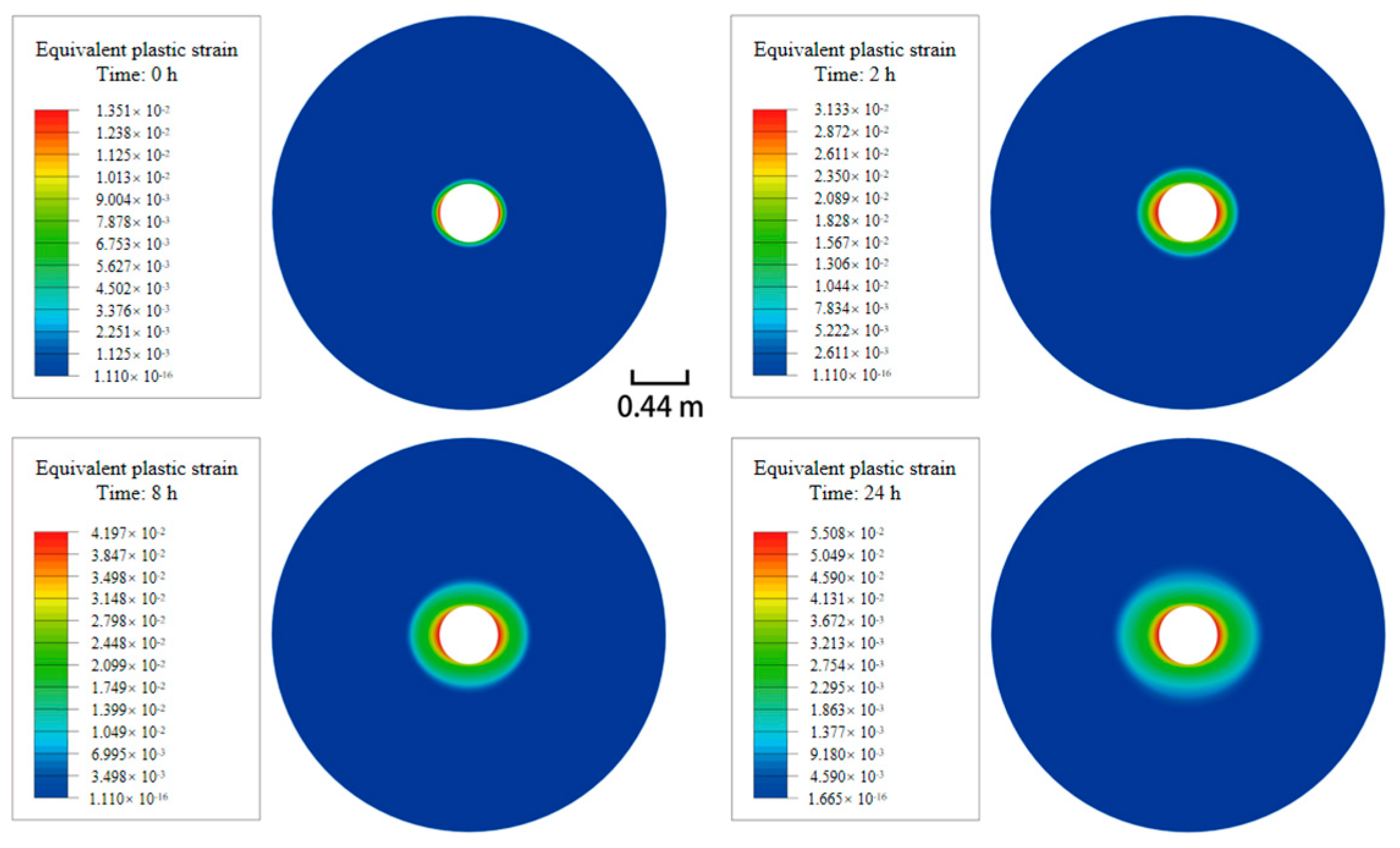
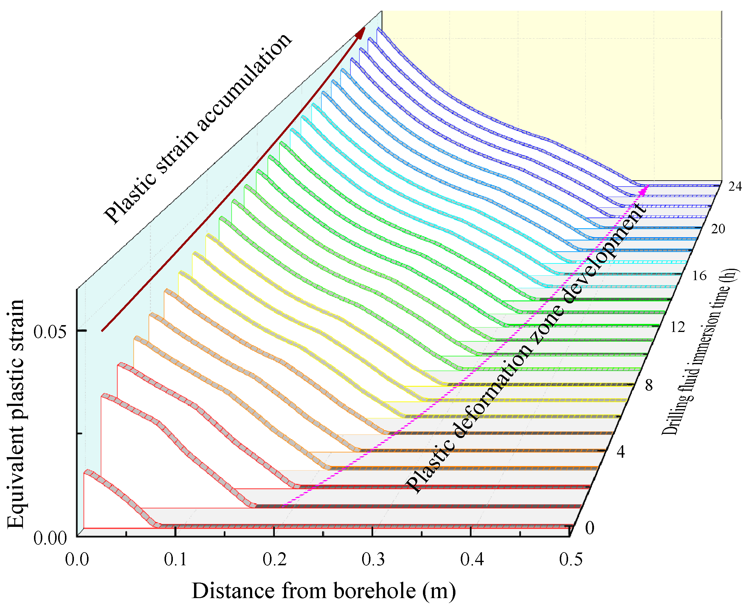
3.2. Mechanical Responses of Strata around Boreholes during Drilling in Permafrost

Using the established model, the evolution of the temperature field, stress field, and plastic zone around boreholes over various time periods was analyzed for permafrost strata. The study investigated the mechanical responses of the strata before and after thawing around the boreholes, as well as the mechanical mechanisms affecting borehole wall stability. Additionally, the research examined the yield ranges and levels of strata around boreholes under different drilling fluid densities. The impacts of drilling fluid density and the thawing extent of permafrost on the yielding behavior of strata were also explored. Finally, the optimal drilling fluid density was determined for different depths and yield criteria.
Figure 4 presents temperature, elastic modulus, cohesion and internal friction angle distribution of formation around borehole. Figure 5 presents cloud diagrams of plastic strain distribution in the strata around boreholes (based on results within a 1.5 m radius) and the evolution curves of plastic strain over time. The data indicate a significant time-dependent effect on plastic deformation around boreholes in permafrost strata. Initially, due to stress concentration, a plastic yield zone forms near the borehole, with the maximum plastic strain reaching 1.35% in the direction of the minimum horizontal geostress on the borehole walls. This plastic yield zone is elliptical and expands up to 0.077 m from the borehole walls. As thawing progresses, the plastic yield zone enlarges; eight hours after the borehole opening, the zone area increases to 0.28 square meters and the maximum plastic strain on the borehole wall rises to 4.20%. After 24 h, the area of the plastic yield zone expands to 0.39 square meters, with the maximum plastic strain reaching 5.5%. The evolution of the plastic yield zone is governed by the stress state, with strata entering a plastic yield state when the stress reaches the yield limit according to the Mohr–Coulomb plasticity criterion. Figure 6 shows the actual and critical values of the maximum principal stress in the strata around the borehole at different time points. Initially, the maximum principal stress within 0.077 m from the borehole walls meets the critical stress threshold, leading to plastic deformation accumulation in this range. As plastic flow occurs, the maximum principal stress at the borehole walls decreases and stress levels drop sharply in the thawing permafrost. Secondary stress concentrations develop in the unthawed formation, causing additional areas to enter a plastic deformation state. Two hours after the borehole is opened, the extent of plastic deformation expands to 0.19 m from the borehole wall, increasing to 0.4 m after 24 h. Thus, secondary stress concentration in the unthawed formation, combined with the mechanical property deterioration of the thawed formation due to high-temperature drilling fluids is a key factor contributing to the continuous expansion of the plastic deformation zone.
At the same time, it can be seen from the evolution of stress states of soils that the areas near borehole walls are always in a state of plastic deformation accumulation. Therefore, large plastic deformation may occur constantly on borehole walls and surrounding soils within a certain period of drilling, as displayed in Figure 7. For permafrost that has strong plasticity, small plastic deformation is acceptable and the failure and collapse of borehole walls occur only under overlarge plastic strain. Therefore, supposing that a borehole collapses when the plastic strain of strata around the borehole exceeds a critical value ( ε e p > ε o ), then the borehole expansion rate κ = L / R in permafrost can be defined. Therein, R represents the radius of the borehole and L is the farthest distance of the collapsed strata to the borehole wall. By defining different critical values of plastic strain, evolution curves of the borehole expansion rate with time can be drawn, as shown in Figure 8. It can be seen that the lower the defined critical value of plastic strain is, the larger the borehole expansion rate. For instance, when the critical value of plastic strain is 5%, the borehole expansion rate is 11.5% after opening the borehole for 24 h; if the critical value of plastic strain is 1%, the borehole expansion rate will be 92%. It means that for permafrost of different compositions, the lower the resistance to plastic deformation is, the larger the collapse range of boreholes under the same conditions. It also suggests that if the critical value of plastic strain is determined, the borehole expansion rate rises with the increasing time after opening the borehole.
Therefore, the critical value of plastic strain can be defined according to the actual resistance of thawed permafrost to plastic deformation in the drilling process in permafrost, so as to determine the borehole expansion rate and its correlations with the density of drilling fluids. On this basis, one can design a reasonable density of drilling fluids according to practical conditions.

4. Borehole Expansion Rates under Different Conditions

Local collapse of borehole walls is a common issue in practical drilling, particularly in permafrost, which consists of low-strength strata. This section calculates borehole expansion rates under various conditions based on the geological characteristics of permafrost and examines the effects of actual conditions on borehole wall stability. The calculations consider permafrost strata thicknesses of 400, 600, and 800 m (with a strata temperature at the borehole bottom of −1 °C) and a geothermal gradient of 0.03 °C/m. The drilling operation is assumed to last for 48 h. An analysis model is developed to determine borehole expansion rates under different conditions, including permafrost thicknesses, soil depths, drilling fluid densities, and critical values of plastic strain, as detailed in Table 2 and Table 3. Results are not tabulated for the 400-m depth case, as the borehole plastic strain remains below 10%, resulting in no borehole enlargement. In soil mechanics, a plastic strain of 15% is generally considered indicative of failure in weak soils; therefore, plastic strains of 10%, 15%, and 20% are used as benchmarks for critical plastic strain levels.
The results indicate that using normal-temperature drilling fluids for drilling in thin permafrost (up to 400 m) does not result in significant stress concentration around the borehole and thus, borehole collapse is unlikely due to low geostress. For permafrost of greater thickness, such as in shallow strata (0–600 m), borehole collapse and expansion can be effectively prevented with normal-temperature drilling fluids, provided that the fluid density exceeds 1.0 g/cm3. This is because the initial geostress in shallow strata is low and the stress concentration effect after borehole opening is minimal, making it difficult for the borehole wall and surrounding soils to yield. However, in deeper permafrost (600–800 m), where geostress is higher, the stress concentration effect is more pronounced. Additionally, the higher strata temperatures lead to faster heat transfer from the drilling fluids, resulting in a larger thawed area within the same time frame. This combined effect compromises borehole wall stability. To mitigate this, it is essential to control the density of drilling fluids effectively.
Based on the stability requirements and engineering costs for drilling in permafrost strata, the following drilling scheme is proposed. For thin permafrost strata (up to 400 m), normal-temperature drilling fluids can be used directly. In cases of relatively thick permafrost, normal-temperature fluids are also suitable for shallow strata. However, for deeper strata with temperatures close to 0 °C, the density of drilling fluids should be adjusted to enhance the stress state around the borehole. Additionally, increasing the drilling rate can help reduce the thawing area of permafrost, thereby preventing collapse and maintaining borehole wall stability.

5. Conclusions

(1) Thawing and yielding occur in the strata around boreholes when normal-temperature drilling fluids are used in permafrost. This results in an obvious stress drop zone in the thawed permafrost due to the deterioration of elastic parameters. Consequently, secondary stress concentrations develop in the frozen strata, causing some of these strata to enter the plastic deformation stage. The area of plastic yield zones around boreholes continues to expand as the influence range of temperature increases;
(2) Although the area of plastic zones around the boreholes consistently enlarges, only the region close to the borehole walls remains in a state of accumulating plastic deformation. Thus, significant plastic deformation is confined to the vicinity of the borehole walls. Based on this observation, the borehole expansion rate is used to design an effective drilling scheme for permafrost;
(3) When drilling in thin permafrost (up to 400 m thick) with normal-temperature drilling fluids, the stress concentration around the borehole is insufficient to cause collapse. For permafrost of greater thickness, such as in shallow strata (0–600 m), using normal-temperature drilling fluids effectively prevents both collapse of borehole walls and borehole expansion. However, for deeper strata (thicker than 600 m), the density of drilling fluids must be carefully controlled to ensure the stability of the borehole walls.

Author Contributions

Conceptualization, J.S. and Y.L.; methodology, C.Y.; software, Y.L.; validation, M.X.; writing—original draft preparation, J.S. All authors have read and agreed to the published version of the manuscript.

Funding

This work is financially supported by the National Key Research and Development Project (2022YFC2806400), the National Natural Science Foundation of China (51974353, 51704311, 51991362), and the Youth Innovation Team Project in Universities in Shandong Province (2022KJ072).

Data Availability Statement

Data is contained within the article.

Conflicts of Interest

Author Jihui Shi was employed by the company Sinopec Shanghai Offshore Oil & Gas Company. The remaining authors declare that the research was conducted in the absence of any commercial or financial relationships that could be construed as a potential conflict of interest.

References

  1. Liao, Q.; Wang, B.; Chen, X.; Tan, P. Reservoir stimulation for unconventional oil and gas resources: Recent advances and future perspectives. Adv. Geo-Energy Res. 2024, 13, 7–9. [Google Scholar] [CrossRef]
  2. Zhang, L.; Pan, L.; Zou, Y.; Wang, J.; Li, M.; Feng, W. Recent Advances in Reservoir Stimulation and Enhanced Oil Recovery Technology in Unconventional Reservoirs. Processes 2024, 12, 234. [Google Scholar] [CrossRef]
  3. Zhang, J.; Tong, Z.; Niu, J. Exploration and exploitation progress of unconventional oil and gas in China. Adv. Resour. Res. 2021, 1, 13–19. [Google Scholar]
  4. Tang, Y.; Zhao, P.; Li, X.; Fang, X.; Yang, P. Numerical Simulation and Experimental Test of the Sliding Core Dynamics of a Pressure Controlled Jet Crushing Tool for Natural Gas Hydrate Exploitation. Processes 2022, 10, 1033. [Google Scholar] [CrossRef]
  5. Yuan, S.; Lei, Z.; Li, J.; Yao, Z.; Li, B.; Wang, R.; Liu, Y.; Wang, Q. Key theoretical and technical issues and countermeasures for effective development of Gulong shale oil, Daqing Oilfield, NE China. Pet. Explor. Dev. 2023, 50, 638–650. [Google Scholar] [CrossRef]
  6. Bird, K.-J.; Charpentier, R.-R.; Gautier, D.-L.; Houseknecht, D.-W.; Klett, T.-R.; Pitman, J.-K.; Moore, T.-E.; Schenk, C.-J.; Tennyson, M.-E.; Wandrey, C.-R. Circum-Arctic Resource Appraisal: Estimates of Undiscovered Oil and Gas North of the Arctic Circle; Fact Sheet; U.S. Geological Survey: Reston, VA, USA, 2008. [CrossRef]
  7. He, R.; Jin, H. Permafrost and cold-region environmental problems of the oil product pipeline from Golmud to Lhasa on the Qinghai–Tibet Plateau and their mitigation. Cold Reg. Sci. Technol. 2010, 64, 279–288. [Google Scholar] [CrossRef]
  8. Amberg, S.; Littke, R.; Lutz, R.; Klitzke, P.; Sachse, V. Influence of pleistocene glaciation on petroleum systems and gas hydrate stability in the olga basin region, barents sea. J. Pet. Geol. 2024, 47, 191–242. [Google Scholar] [CrossRef]
  9. Vernikovsky, V.-A.; Dobretsov, N.-L.; Metelkin, D.-V.; Matushkin, N.Y.; Koulakov, I.-Y. Concerning tectonics and the tectonic evolution of the Arctic. Russ. Geol. Geophys. 2013, 54, 838–858. [Google Scholar] [CrossRef]
  10. Sekretov, S.-B. Northwestern margin of the East Siberian Sea, Russian Arctic: Seismic stratigraphy, structure of the sedimentary cover and some remarks on the tectonic history. Tectonophysics 2001, 339, 353–371. [Google Scholar] [CrossRef]
  11. Wu, Q.; Liu, Y.; Zhang, J.; Tong, C. A review of recent frozen soil engineering in permafrost regions along Qinghai-Tibet Highway, China. Permafr. Periglac. Process. 2002, 13, 199–205. [Google Scholar]
  12. Li, Y.; Cheng, Y.; Yan, C.; Yang, H.; Gao, Q.; Han, S. Study on the Wellbore Shrinkage during Drilling Operation in Frozen Soil. In Proceedings of the 56th US Rock Mechanics/Geomechanics Symposium, Santa Fe, NM, USA, 26–29 June 2022. [Google Scholar]
  13. Li, Q.; Liu, J.; Wang, S.; Guo, Y.; Han, X.; Li, Q.; Cheng, Y.; Dong, Z.; Li, X.; Zhang, X. Numerical insights into factors affecting collapse behavior of horizontal wellbore in clayey silt hydrate-bearing sediments and the accompanying control strategy. Ocean Eng. 2024, 297, 117029. [Google Scholar] [CrossRef]
  14. Li, K.; Yin, Z. State of the Art of Coupled Thermo–hydro-Mechanical–Chemical Modelling for Frozen Soils. In Archives of Computational Methods in Engineering; Springer: Berlin/Heidelberg, Germany, 2024; pp. 1–58. [Google Scholar]
  15. Jia, H.; Wang, T.; Chen, W.; Ding, S.; Luo, T.; Sun, Q. Microscopic mechanisms of microwave irradiation thawing frozen soil and potential application in excavation of frozen ground. Cold Reg. Sci. Technol. 2021, 184, 103248. [Google Scholar] [CrossRef]
  16. Wu, Z.; Xu, L.; Wang, H.; Li, B.; Ke, K.; Sun, Y. Numerical simulation of insulated drilling technique with refrigerant fluid in the Arctic region. Appl. Therm. Eng. 2024, 253, 123788. [Google Scholar] [CrossRef]
  17. Yakoby, A.; Hatzor, Y.-H.; Pinkert, S. Enhanced borehole stability analysis for geological waste disposal under conditions of in-situ stress uncertainty: The case of Yamin Plain, Israel. Eng. Geol. 2023, 321, 107137. [Google Scholar] [CrossRef]
  18. Gao, X.; Wang, M.; Shi, X.; Li, X.; Zhang, M. Risk Assessment Method for Analyzing Borehole Instability Considering Formation Heterogeneity. Processes 2023, 12, 70. [Google Scholar] [CrossRef]
  19. Feng, S.; Chen, J.; Jones, S.-B.; Flerchinger, G.; Dyck, M.; Filipovic, V.; Hu, Y.; Si, B.; Lv, J.; Wu, Q.; et al. Miscellaneous methods for determination of unfrozen water content in frozen soils. J. Hydrol. 2024, 631, 130802. [Google Scholar] [CrossRef]
  20. Li, Y.; Cheng, Y.; Yan, C.; Song, L.; Zhou, X.; Niu, C. Influence of drilling fluid temperature on borehole shrinkage during drilling operation in cold regions. J. Pet. Sci. Eng. 2020, 190, 107050. [Google Scholar] [CrossRef]
  21. Kostina, A.; Zhelnin, M.; Plekhov, O.; Levin, L. Numerical simulation of stress-strain state in frozen wall during thawing. Procedia Struct. Integr. 2021, 32, 101–108. [Google Scholar] [CrossRef]
  22. Li, L.; Yang, J.; Ke, K.; Li, L.; Dong, M.; Zhu, G.; Cui, T. Research on the Influence Factors of Wellhead Thaw-Settlement in Polar Drilling. In Proceedings of the ISOPE International Ocean and Polar Engineering Conference, Rhodes, Greece, 16–21 June 2024. [Google Scholar]
  23. Zhou, X.; Su, Y.; Cheng, Y.; Li, Q. Evaluation of Thermal Insulation of Vacuum-Insulated Casing to Prevent Uncontrollable Melting of Ice and Borehole Instability in Permafrost. Processes 2024, 12, 1389. [Google Scholar] [CrossRef]
  24. Sun, J.; Wang, Z.; Liu, J.; Lyu, K.; Huang, X.; Zhang, X.; Huang, N. Research progress and development direction of low-temperature drilling fluid for Antarctic region. Pet. Explor. Dev. 2022, 49, 1161–1168. [Google Scholar] [CrossRef]
  25. Zhao, X.; Qiu, Z.; Huang, W.; Wang, M. Mechanism and method for controlling low-temperature rheology of water-based drilling fluids in deepwater drilling. J. Pet. Sci. Eng. 2017, 154, 405–416. [Google Scholar] [CrossRef]
  26. Jiang, G.; Ning, F.; Zhang, L.; Tu, Y. Effect of agents on hydrate formation and low-temperature rheology of polyalcohol drilling fluid. J. Earth Sci. 2011, 22, 652–657. [Google Scholar] [CrossRef]
  27. Shi, L.; Chen, S.; Li, M. Research on the characteristic parameters of Harbin seasonal frozen soils. Chin. J. Rock Mech. Eng. 2019, 38, 1053–1063. [Google Scholar]
  28. Li, Y.; Cheng, Y.; Yan, C.; Xue, M.; Niu, C.; Gao, Y.; Wang, T. Simulating the effect of frozen soil thaw on wellhead stability during oil and gas drilling operations in arctic waters. J. Cold Reg. Eng. 2020, 34, 04020026. [Google Scholar] [CrossRef]
  29. Wang, Z.; Wang, X.; Sun, B.; Deng, X.; Zhao, Y.; Gao, Y.; Li, H. Analysis on wellhead stability during drilling operation in arctic permafrost region. In Proceedings of the International Conference on Offshore Mechanics and Arctic Engineering, Trondheim, Norway, 25–30 June 2017; Volume 57762, p. V008T11A008. [Google Scholar]
  30. Christopher, H.; Serkan, I.; David, J.; Lee, Z. Heat generation during bone drilling: A comparison between industrial and orthopaedic drill bits. J. Orthop. Trauma 2017, 31, e55–e59. [Google Scholar]
  31. Wang, Y.; Liu, Y.; Cui, Y.; Guo, W.; Lv, J. Numerical simulation of soil freezing and associated pipe deformation in ground heat exchangers. Geothermics 2018, 74, 112–120. [Google Scholar] [CrossRef]
  32. Lan, H.; Yan, X.; Moore, I.-D. Mud infiltration and travel paths during mud loss experiments on horizontal borehole stability. Tunn. Undergr. Space Technol. 2024, 144, 105565. [Google Scholar] [CrossRef]
  33. Ren, Z.; Liu, J.; Jiang, H.; Wang, E. Experimental study and simulation for unfrozen water and compressive strength of frozen soil based on artificial freezing technology. Cold Reg. Sci. Technol. 2023, 205, 103711. [Google Scholar] [CrossRef]
  34. Xu, X.; Wang, J.; Zhang, L. Physics of Permafrost; Science Press: Beijing, China, 2001; pp. 39–45. [Google Scholar]
  35. SIMULIA. Abaqus Version 2016 Analysis User’s Guide; Dassault Systemes: Providence, RI, USA, 2016. [Google Scholar]
  36. Song, B.; Cheng, Y.; Yan, C.; Lyu, Y.; Wei, J.; Ding, J.; Li, Y. Seafloor subsidence response and submarine slope stability evaluation in response to hydrate dissociation. J. Nat. Gas Sci. Eng. 2019, 65, 197–211. [Google Scholar] [CrossRef]
  37. Mukherjee, D.; Tewary, U.; Kumar, S.; Karagadde, S.; Verma, R.-K.; Sambandam, M.; Samajdar, I. Imposed thermal gradients and resultant residual stresses: Physical and numerical simulations. Mater. Sci. Technol. 2020, 36, 1020–1036. [Google Scholar] [CrossRef]
  38. Gao, Q.; Han, S.; Cheng, Y.; Yan, C.; Sun, Y.; Han, Z. Effects of non-uniform pore pressure field on hydraulic fracture propagation behaviors. Eng. Fract. Mech. 2019, 221, 106682. [Google Scholar] [CrossRef]
  39. Li, Y.; Cheng, Y.; Yan, C.; Song, L.; Liu, H.; Tian, W.; Ren, X. Mechanical study on the wellbore stability of horizontal wells in natural gas hydrate reservoirs. J. Nat. Gas Sci. Eng. 2020, 79, 103359. [Google Scholar] [CrossRef]
Figure 1. Schematic diagram of borehole expansion in permafrost layer.
Processes 12 01819 g001
Figure 2. Triaxial mechanical test and test results.
Processes 12 01819 g002
Figure 3. Geometrical model and boundary conditions.
Processes 12 01819 g003
Figure 4. Distributions of temperature, elastic modulus, cohesion, and internal friction angle of strata around boreholes.
Processes 12 01819 g004
Figure 5. Distribution of plastic strain around boreholes after different soaking in drilling fluids.
Processes 12 01819 g005
Figure 6. Distribution of the maximum principal stress in strata around boreholes in the direction of the minimum horizontal geostress.
Processes 12 01819 g006
Figure 7. Evolution of plasticity of strata around boreholes.
Processes 12 01819 g007
Figure 8. Distribution of the borehole expansion rate.
Processes 12 01819 g008
Table 1. Physical parameters of permafrost strata [20,28].
ParameterValue
Thermal conductivity of soils/W·(m·°C)−11.383
Thermal conductivity of ice/W·(m·°C)−12.22
Thermal conductivity of water/W·(m·°C)−10.55
Specific heat capacity of soils/J·(kg·°C)−1982
Specific heat capacity of ice/J·(kg·°C)−14200
Specific heat capacity of water/J·(kg·°C)−11930
Heat transfer coefficient/W·(m2·K)−1750
Phase-change latent heat of ice/J·(mol)−1333,000
Density of dry soils/kg·(m)−31450
Density of ice and water/kg·(m)−31000
Coefficient of thermal expansion of soils9.67 × 10−6
Coefficient of thermal expansion of ice (T ≤ 0 °C)−5.1 × 10⁻⁵
Coefficient of thermal expansion of water (0 °C < T ≤ 4 °C)−1.67 × 10⁻⁵
Coefficient of thermal expansion of water (T > 4 °C)2.93 × 10⁻⁵
Permeability of permafrost (darcy)1 × 10⁻¹⁴
Permeability of thawed permafrost (darcy)1 × 10⁻⁸
Poisson’s ratio of soils0.35
Table 2. Relationships between the density of drilling fluids and the borehole expansion rate in permafrost with a thickness of 600 m.
Drilling Fluid Density (g/cm3)
Depth/TemperatureCritical Plasticity
Strain (%)
1.01.051.11.151.21.251.3
300 m/−10 °C100%0%0%0%0%0%0%
150%0%0%0%0%0%0%
200%0%0%0%0%0%0%
400 m/−7 °C100%0%0%0%0%0%0%
150%0%0%0%0%0%0%
200%0%0%0%0%0%0%
500 m/−4 °C1015%13%11%9%8%6%4%
151%0%0%0%0%0%0%
200%0%0%0%0%0%0%
600 m/−1 °C1031%27%23%19%17%14%10%
1519%16%12%9%7%4%2%
2011%9%6%4%1%0%0%
Table 3. Relationships between the density of drilling fluids and the borehole expansion rate in permafrost with a thickness of 800 m.
Drilling Fluid Density (g/cm3)
Depth/TemperatureCritical Plasticity
Strain (%)
1.01.051.11.151.21.251.3
300 m/−16 °C100%0%0%0%0%0%0%
150%0%0%0%0%0%0%
200%0%0%0%0%0%0%
400 m/−13 °C100%0%0%0%0%0%0%
150%0%0%0%0%0%0%
200%0%0%0%0%0%0%
500 m/−10 °C100%0%0%0%0%0%0%
150%0%0%0%0%0%0%
200%0%0%0%0%0%0%
600 m/−7 °C1020%14%9%0%0%0%0%
150%0%0%0%0%0%0%
200%0%0%0%0%0%0%
700 m/−4 °C1020%18%15%13%11%8%6%
159%7%5%4%1%0%0%
203%1%0%0%0%0%0%
800 m/−1 °C1074%66%60%52%46%40%35%
1552%46%40%35%30%26%21%
2040%34%29%25%21%17%16%
Disclaimer/Publisher’s Note: The statements, opinions and data contained in all publications are solely those of the individual author(s) and contributor(s) and not of MDPI and/or the editor(s). MDPI and/or the editor(s) disclaim responsibility for any injury to people or property resulting from any ideas, methods, instructions or products referred to in the content.

