


The Analysis of Differential Saturation in Shale Oil Accompanied by an Enhanced Classification of Fluid Distribution within the Pore


Abstract
1. Introduction
2. Methodology
2.1. Samples Collection
2.2. Experimental Procedures
- (1)
- Close the outlet end of the high-temperature and high-pressure containment device, the deionized water is injected into the high-temperature and high-pressure containment device from the injection end at a speed of 0.1 mL/min. The valve of the injection end would be closed when the pressure reaches 20 MPa, the instrument would be maintained for 24 h to check the sealing.
- (2)
- Launch the NMR T2 spectrum of the pre-treated standard plunger core to obtain the NMR T2 spectrum of the dry core.
- (3)
- Place the shale core in a high-temperature and high-pressure containment device, the measurement pressure and temperature would be set as 20 MPa and 60 °C, respectively; the NMR T2 spectrum scanning would be launched when the core sample is saturated for 48 h.
- (4)
- Repeat step (3) with a step length of 2 d, and carry out NMR T2 spectra scanning of the shale core at different saturation times: 2 d, 4 d, 6 d, 8 d, 10 d, 12 d, and 14 d, and consider the core saturated when there is no obvious change in the NMR T2 spectra curve.
2.3. Selection of NMR Instrument Parameters
2.4. Classification of Fluid Distribution Pores
3. Results and Discussion
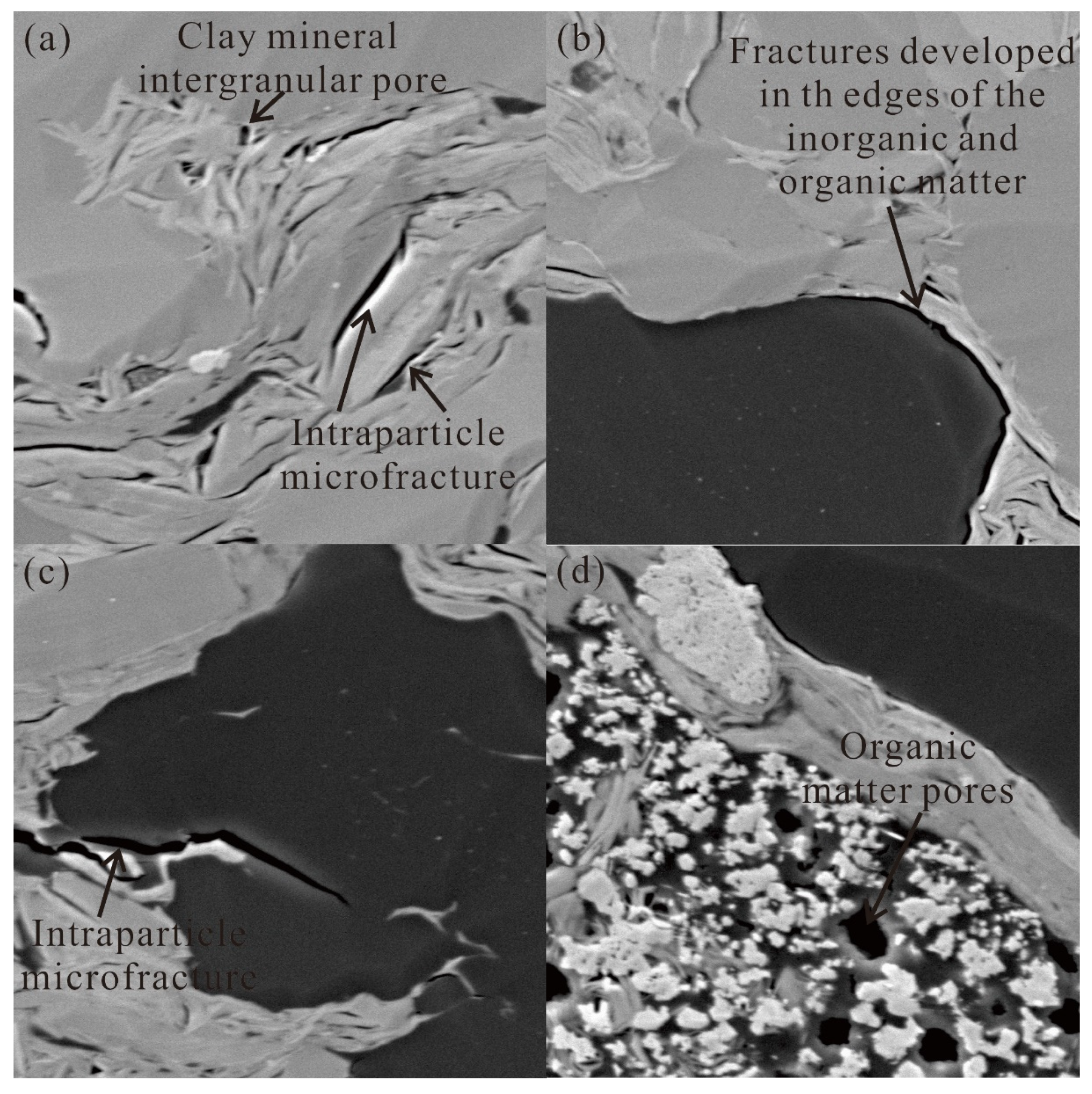
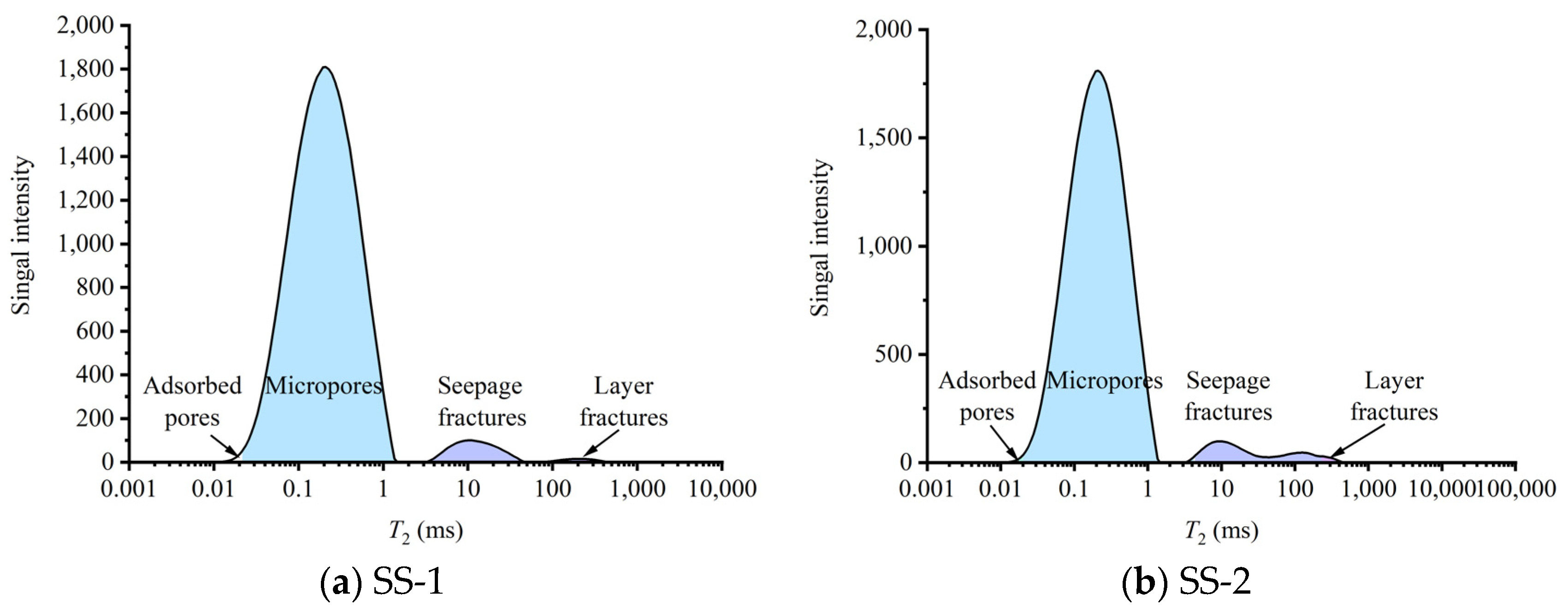
3.1. Pore Types in Shale
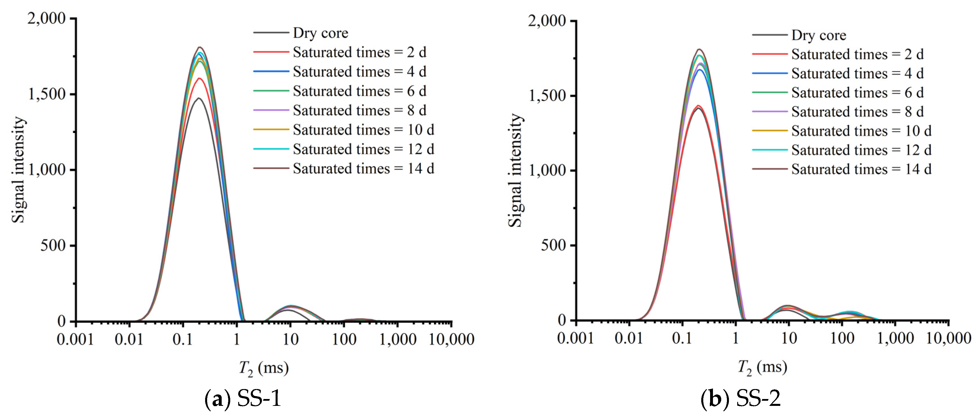
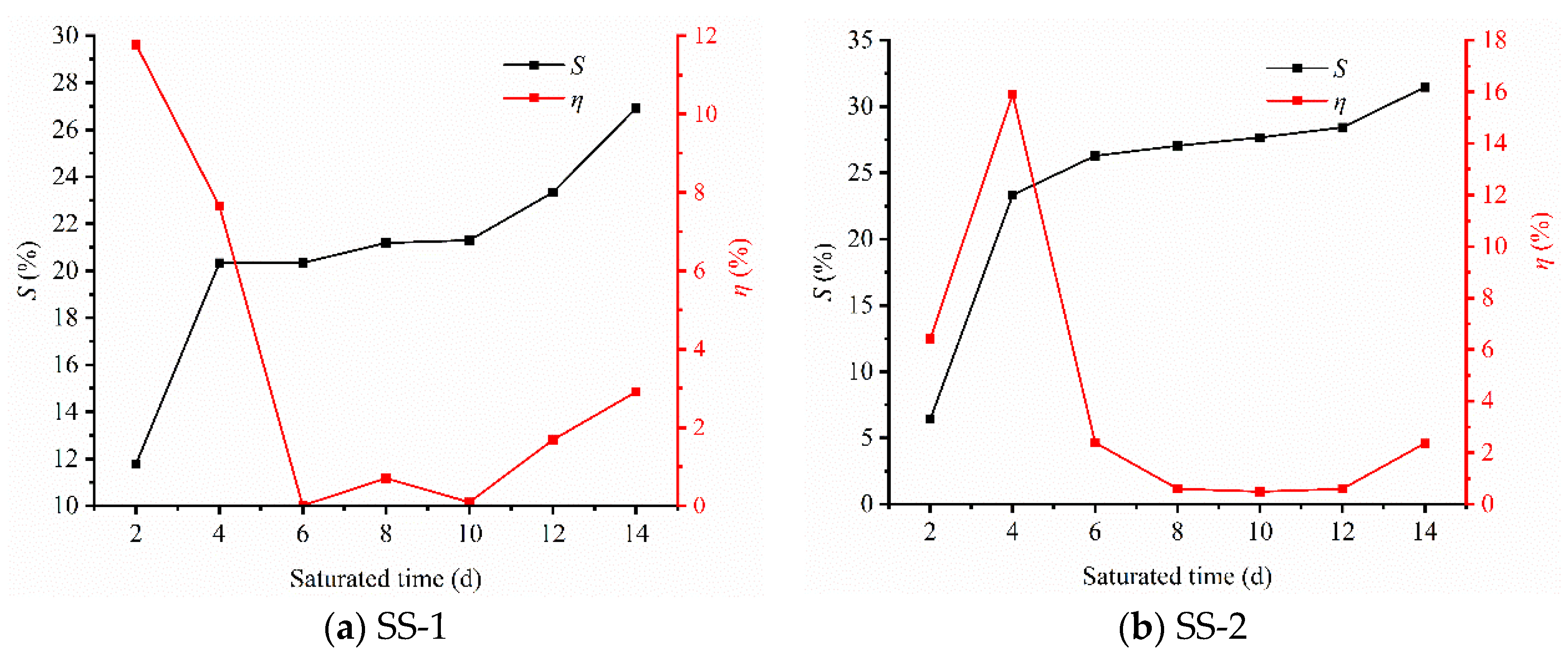
3.2. Shale Oil Saturation Characteristics
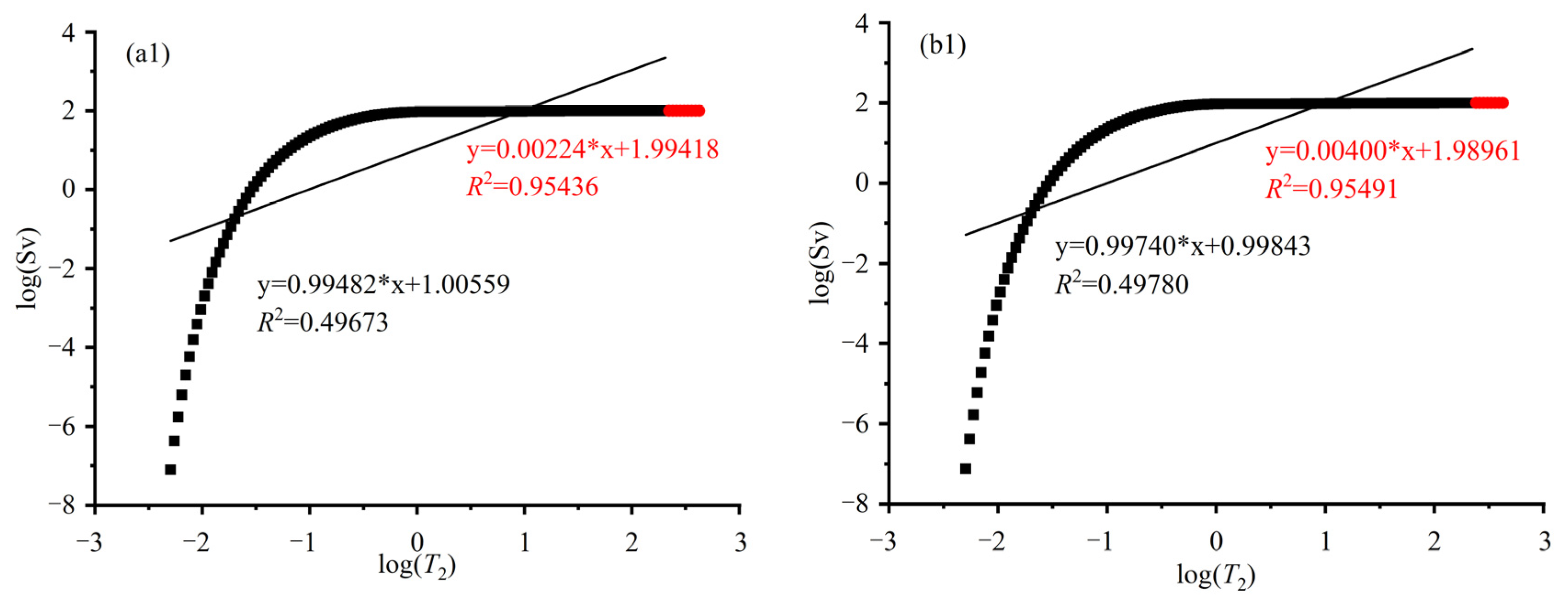
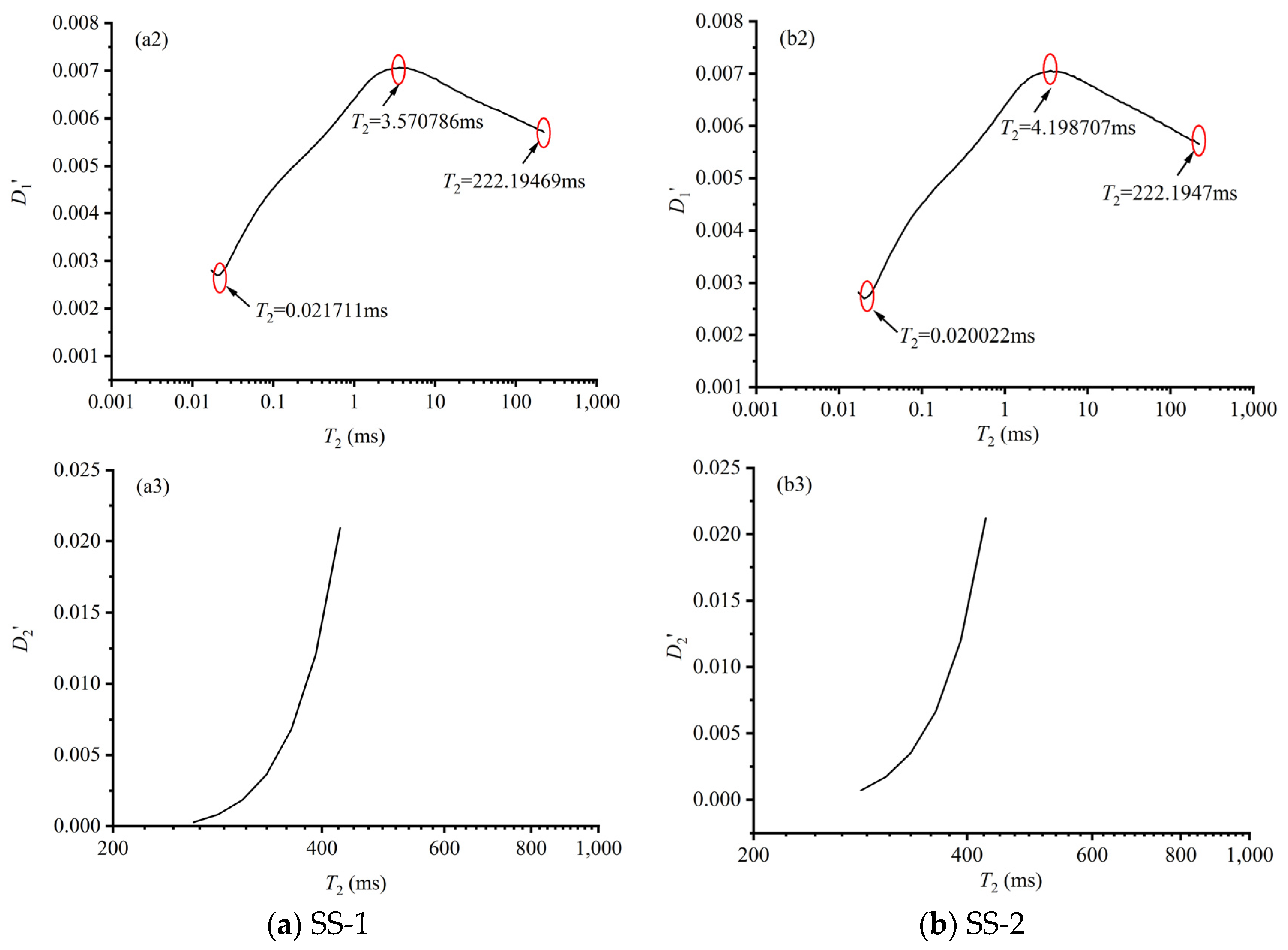
3.3. Fluid Distribution Pore Division
3.4. Characteristics of Fluid Differential Saturation in Different Types of Pore Spaces
3.5. Implications of Fluid Saturation for Shale Oil Production
4. Conclusions
Author Contributions
Funding
Data Availability Statement
Acknowledgments
Conflicts of Interest
References
- Reynolds, D.B.; Umekwe, M.P. Shale-oil development prospects: The role of shale-gas in developing shale-oil. Energies 2019, 12, 3331. [Google Scholar] [CrossRef]
- Feng, Q.; Xu, S.; Xing, X.; Zhang, W.; Wang, S. Advances and challenges in shale oil development: A critical review. Adv. Geo-Energy Res. 2020, 4, 406–418. [Google Scholar] [CrossRef]
- Zou, C.; Yang, Z.; Cui, J.; Zhu, R.; Hou, L.; Tao, S.; Yuan, X.; Wu, S.; Lin, S.; Wang, L.; et al. Formation mechanism, geological characteristics and development strategy of nonmarine shale oil in China. Pet. Explor. Dev. 2013, 40, 15–27. [Google Scholar] [CrossRef]
- Hu, S.; Zhao, W.; Hou, L.; Yang, Z.; Zhu, R.; Wu, S.; Bai, B.; Jin, X. Development potential and technical strategy of continental shale oil in China. Pet. Explor. Dev. 2020, 47, 877–887. [Google Scholar] [CrossRef]
- Wang, X.; Li, J.; Jiang, W.; Zhang, H.; Feng, Y.; Yang, Z. Characteristics, current exploration practices, and prospects of continental shale oil in China. Adv. Geo-Energy Res. 2020, 6, 454–459. [Google Scholar] [CrossRef]
- Xu, Y.; Lun, Z.; Pan, Z.; Wang, H.; Zhou, X.; Zhao, C.; Zhang, D. Occurrence space and state of shale oil: A review. J. Pet. Sci. Eng. 2022, 211, 110183. [Google Scholar] [CrossRef]
- Ritter, U. Solubility of petroleum compounds in kerogen. Org. Geochem. 2003, 34, 319–326. [Google Scholar] [CrossRef]
- Gorynski, K.E.; Tobey, M.H.; Enriquez, D.A.; Smagala, T.M.; Dreger, J.L.; Newhart, R.E. Quantification and characterization of hydrocarbon-filled porosity in oil-rich shales using integrated thermal extraction, pyrolysis, and solvent extraction. AAPG Bull. 2019, 103, 723–744. [Google Scholar] [CrossRef]
- Song, Y.Q.; Kausik, R. NMR application in unconventional shale reservoirs—A new porous media research frontier. Prog. Nucl. Mag. Res. Sp. 2019, 112–113, 17–33. [Google Scholar] [CrossRef]
- Liu, Z.; Liu, D.; Cai, Y.; Yao, Y.; Pan, Z.; Zhou, Y. Application of nuclear magnetic resonance (NMR) in coalbed methane and shale reservoirs: A review. Int. J. Coal Geol. 2020, 218, 103261. [Google Scholar] [CrossRef]
- Yuan, Y.; Rezae, R.; Zhou, M.F.; Iglauer, S. A comprehensive review on shale studies with emphasis on nuclear magnetic resonance (NMR) technique. Gas Sci. Eng. 2023, 120, 205163. [Google Scholar] [CrossRef]
- Chen, D.; Pang, X.; Jiang, F.; Liu, G.; Pan, Z.; Liu, Y. Shale oil potential and mobility of low-maturity lacustrine shales: Implications from NMR analysis in the Bohai bay basin. Energy Fuel. 2021, 35, 2209–2223. [Google Scholar] [CrossRef]
- Zhang, P.; Lu, S.; Li, J.; Chang, X. 1D and 2D nuclear magnetic resonance (NMR) relaxation behaviors of protons in clay, kerogen and oil-bearing shale rocks. Mar. Petrol. Geol. 2020, 114, 104210. [Google Scholar] [CrossRef]
- Fleury, M.; Romero-Sarmiento, M. Characterization of shales using T1-T2 NMR maps. J. Pet. Sci. Eng. 2016, 137, 55–62. [Google Scholar] [CrossRef]
- Zou, J.; Hu, W.; Lun, Z.; Zhou, X.; Zhao, C.; Wang, H.; Meng, Z.; Zhu, P.; Tang, X.; Zhang, D. Recovery of adsorbed and free oil in shale formations by CO2 injection: An experimental study using 1D- and 2D-NMR. Energy Fuel 2024, 38, 12989–13001. [Google Scholar] [CrossRef]
- Wang, J.; Lu, S.; Zhang, P.; Li, Q.; Yin, Y.; Li, W.; Zhou, N.; Chen, G.; Yi, Y.; Wu, C. Characterization of shale oil and water micro-occurrence based on a novel method for fluid identification by NMR T2 spectrum. Fuel 2024, 374, 132426. [Google Scholar] [CrossRef]
- Tian, H.; He, K.; Huangfu, Y.; Liao, F.; Wang, X.; Zhang, S. Oil content and mobility in a shale reservoir in Songliao Basin, Northeast China: Insights from combined solvent extraction and NMR methods. Fuel 2024, 357 Pt A, 129678. [Google Scholar] [CrossRef]
- Li, J.; Lu, S.; Jiang, C.; Wang, M.; Chen, Z.; Chen, G.; Li, J.; Lu, S. Characterization of shale pore size distribution by NMR considering the influence of shale skeleton signals. Energy Fuel 2019, 33, 6361–6372. [Google Scholar] [CrossRef]
- Liu, J.; Xie, R.; Guo, J.; Xu, C. Study of nuclear magnetic resonance response mechanism in shale oil and correction of petrophysical parameters. Fuel 2024, 358 Pt A, 130162. [Google Scholar] [CrossRef]
- Zhang, C.; Jiang, F.; Hu, T.; Chen, D.; Huang, L.; Jiang, Z.; Wang, X.; Liu, Z.; Wu, Y.; Lv, J.; et al. Oil occurrence state and quantity in alkaline lacustrine shale using a high-frequency NMR technique. Mar. Petrol. Geol. 2023, 154, 106302. [Google Scholar] [CrossRef]
- Wang, H.; Lun, Z.; Lv, C.; Lang, D.; Luo, M.; Zhao, Q.; Zhao, C. Nuclear-Magnetic-Resonance study on oil mobilization in shale exposed to CO2. SPE J. 2020, 25, 432–439. [Google Scholar] [CrossRef]
- Pang, X.; Li, M.; Li, B.; Wang, T.; Hui, S.; Liu, Y.; Liu, G.; Hu, T.; Xu, T.; Jiang, F.; et al. Main controlling factors and movability evaluation of continental shale oil. Earth-Sci. Rev. 2023, 243, 104472. [Google Scholar] [CrossRef]
- Wang, M.; Ma, R.; Li, J.; Lu, S.; Li, C.; Guo, Z.; Li, Z. Occurrence mechanism of lacustrine shale oil in the Paleogene Shahejie Formation of Jiyang Depression, Bohai Bay Basin, China. Pet. Explor. Dev. 2019, 46, 833–846. [Google Scholar] [CrossRef]
- Zhu, X.; Cai, J.; Liu, Q.; Li, Z.; Zhang, X. Thresholds of petroleum content and pore diameter for petroleum mobility in shale. AAPG Bull. 2019, 103, 605–617. [Google Scholar] [CrossRef]
- Han, H.; Guo, C.; Zhong, N.N.; Pang, P.; Chen, S.J.; Lu, J.G.; Gao, Y. Pore structure evolution of lacustrine shales contanining Type I organic matter from the Upper Cretaceous Qingshankou Formation, Songliao Basin, China: A study of artificial samples from hydrous pyrolysis experiments. Mar. Petrol. Geol. 2019, 104, 375–388. [Google Scholar] [CrossRef]
- Gao, H.; Li, H. Determination of movable fluid percentage and movable fluid porosity in ultra-low permeability sandstone using nuclear magnetic resonance (NMR) technique. J. Pet. Sci. Eng. 2015, 133, 258–267. [Google Scholar] [CrossRef]
- Hu, Y.; Guo, Y.; Shangguan, J.; Zhang, J.; Song, Y. Fractal characteristics and model applicability for pores in tight gas sandstone reservoirs: A case study of the Upper Paleozoic in Ordos Basin. Energy Fuel 2020, 34, 16059–16072. [Google Scholar] [CrossRef]
- Peng, Y.; Zhou, C.; Fan, Y.; Li, C.; Yuan, C.; Cong, Y. A new permeability calculation method using nuclear magnetic resonance logging based on pore sizes: A case study on bioclastic limestone reservoirs in the A oilfield of the Mid-Ease. Pet. Explor. Dev. 2018, 45, 183–192. [Google Scholar]
- Wang, F.; Zeng, F.; Wang, L.; Hou, X.; Cheng, H.; Gao, J. Fractal analysis of tight sandstone petrophysical properties in unconventional oil reservoirs with NMR and rate-controlled porosimetry. Energy Fuel 2021, 35, 3753–3765. [Google Scholar] [CrossRef]
- Li, T.; Gao, H.; Wang, M.; Feng, Y.; Wang, C.; Cheng, Z. Study on movability of spontaneous imbibition oil recovery from tight reservoirs based on nuclear magnetic resonance pore classification method. Chin. J. Theor. Appl. Mech. 2023, 55, 645–657. (In Chinese) [Google Scholar]
- Li, T.; Gao, H.; Ni, J.; Wang, C.; Cheng, Z.; Xue, J.; Luo, K. Research on the differential oil producing in the various scale pores under different CO2 flooding modes with a fluid distribution pore classification method. Energy Fuel 2023, 37, 3775–3784. [Google Scholar] [CrossRef]
- Li, T.; Gao, H.; Wang, C.; Cheng, Z.; Xue, J.; Zhang, Z.; Luo, K.; Li, N.; Liu, X.; Cao, J. Oil utilization degree at various pore sizes via different displacement methods. J. Pet. Expl. Prod. Technol. 2022, 12, 2271–2287. [Google Scholar] [CrossRef]
- Loucks, R.G.; Reed, R.M.; Ruppel, S.C.; Hammes, U. Spectrum of pore types and networks in mudrocks and a descriptive classification for matrix-related mudrock pores. AAPG Bull. 2012, 96, 1071–1098. [Google Scholar] [CrossRef]
- Slatt, E.M.; O’Neal, N.R. Pore types in the Barnett and Woodford gas shales: Contribution to understanding gas storage and migration pathways in fine-grained rocks. AAPG Bull. 2011, 95, 2017–2030. [Google Scholar] [CrossRef]
- Yu, B. Classification and characterization of gas shale pore system. Earth Sci. Front. 2013, 20, 211–220. (In Chinese) [Google Scholar]
- Looyestijn, W.J.; Hofman, J. Wettability-index determination by nuclear magnetic resonance. SPE Reserv. Eval. Eng. 2006, 9, 146–153. [Google Scholar] [CrossRef]
- Li, X.; Kang, Y.; Haghighi, M. Investigation of pore size distributions of coals with different structures by nuclear magnetic resonance (NMR) and mercury intrusion porosimetry (MIP). Meas 2018, 116, 122–128. [Google Scholar] [CrossRef]


| Properties Parameters | Shale Samples | ||
|---|---|---|---|
| SS-1 | SS-2 | ||
| Porosity (%) | 0.99 | 1.01 | |
| Permeability (×10−3 μm2) | 0.1231 | 0.1661 | |
| Inorganic mineralscontent (%) | Quartz | 25.40 | 24.40 |
| Potassium feldspar | 6.30 | 2.60 | |
| Plagioclase feldspar | 27.90 | 27.70 | |
| Calcite | 0.40 | / | |
| Dolomite | 0.60 | / | |
| Pyrite | / | 0.60 | |
| Muscovitize | / | 3.40 | |
| Clay minerals | 39.40 | 41.30 | |
| I/S | 36.20 | 27.00 | |
| It | 15.50 | 19.20 | |
| Kao | 18.50 | 18.80 | |
| C | 29.80 | 35.00 | |
Disclaimer/Publisher’s Note: The statements, opinions and data contained in all publications are solely those of the individual author(s) and contributor(s) and not of MDPI and/or the editor(s). MDPI and/or the editor(s) disclaim responsibility for any injury to people or property resulting from any ideas, methods, instructions or products referred to in the content. |
© 2024 by the authors. Licensee MDPI, Basel, Switzerland. This article is an open access article distributed under the terms and conditions of the Creative Commons Attribution (CC BY) license (https://creativecommons.org/licenses/by/4.0/).
Share and Cite
Li, T.; Li, X.; Zhu, X. The Analysis of Differential Saturation in Shale Oil Accompanied by an Enhanced Classification of Fluid Distribution within the Pore. Processes 2024, 12, 1870. https://doi.org/10.3390/pr12091870
Li T, Li X, Zhu X. The Analysis of Differential Saturation in Shale Oil Accompanied by an Enhanced Classification of Fluid Distribution within the Pore. Processes. 2024; 12(9):1870. https://doi.org/10.3390/pr12091870
Chicago/Turabian StyleLi, Teng, Xiaohang Li, and Xiulan Zhu. 2024. "The Analysis of Differential Saturation in Shale Oil Accompanied by an Enhanced Classification of Fluid Distribution within the Pore" Processes 12, no. 9: 1870. https://doi.org/10.3390/pr12091870
APA StyleLi, T., Li, X., & Zhu, X. (2024). The Analysis of Differential Saturation in Shale Oil Accompanied by an Enhanced Classification of Fluid Distribution within the Pore. Processes, 12(9), 1870. https://doi.org/10.3390/pr12091870