Article

Investigation of the Upper Safety Operating Pressure Limit for Underground Gas Storage Using the Fault Activation Pressure Evaluation Method

1
Liaohe Oilfield Branch Gas Storage Company of PetroChina, Panjin 124007, China
2
School of Earth Sciences, Northeast Petroleum University, Daqing 163318, China
3
Key Laboratory of Oil & Gas Reservoir and Underground Gas Storage Integrity Evaluation of Heilongjiang PR, Daqing 163318, China
4
FAPS Energy Technology Ltd., Daqing 163318, China
*
Author to whom correspondence should be addressed.
Processes 2024, 12(9), 1910; https://doi.org/10.3390/pr12091910
Submission received: 24 July 2024 / Revised: 27 August 2024 / Accepted: 31 August 2024 / Published: 6 September 2024
(This article belongs to the Section Energy Systems)

Abstract

:
As a crucial reserve for natural gas, the safe operation of underground gas storage facilities is paramount for seasonal peak shaving and emergency supply security. Focusing on the Lei X gas storage facility in the Liaohe Basin of China, this study delves into the mechanical integrity of gas storage facilities and assesses the upper limit pressure for safe operation. Leveraging seismic logging data, we conducted an analysis and statistical evaluation of boundary faults and top cover characteristics, integrating regional stress fields and rock mechanics to evaluate fault activation pressure and cover failure risk using a fault activation pressure assessment method. This research elucidates the maximum safe operating pressure for underground gas storage facilities. The research findings suggest that the sealing layer of the Lei X gas storage reservoir exhibits a predominant hydro-fracturing pattern. Under the existing stress field conditions, the sealing layer demonstrates favorable sealing properties, and the boundary faults remain relatively stable. Moreover, through data extraction and quantitative analysis, this study clearly determined the critical pressure at which each fault is activated and the pressure at which the sealing layer undergoes hydro-fracturing during cyclic injection and the production of gas storage. Considering the activation pressure and fracturing pressure data for the sealing layer, a secure operating pressure of 15.0 MPa was calculated for gas storage operations. This study offers crucial theoretical support for enhancing injection and production efficiency, as well as ensuring the safe operation of Lei X gas storage and providing technical guidance for future adjustments to injection and production schemes.

1. Introduction

Natural gas serves as a vital component within China’s strategy for low-carbon sustainable development due to its status as a clean energy source [1,2,3]. Nonetheless, the current challenge lies in aligning natural gas supply areas with primary consumption markets, necessitating maximal enhancement of peak shaving capabilities within gas storage infrastructure [4,5]. Mahjour et al. provide a comprehensive analysis of technical (such as operational and site characteristics) and non-technical (such as financial, political, and social) risks and uncertainties in Carbon Capture and Storage (CCS) projects, summarize practical strategies and methods to enhance the feasibility of CCS, and offer specific recommendations to increase the potential for CCS project success [6]. The broader operational pressure range directly corresponds with increased capacity, and subsequently augments peak shaving potential [7]. Thus, elevating upper limit pressures within these facilities stands poised to bolster their efficacy. However, elevated operational pressures carry inherent risks, such as potential seepage through overlying strata into shallower layers [8], destabilization leading to natural gas release along faults, or, in extreme scenarios, triggering large-scale seismic events that imperil surface installations and jeopardize overall safety protocols. By injecting high-pressure liquids or gases into subsurface rock formations, the stress distribution and physical properties of the rocks are altered, thereby triggering seismic activity. This phenomenon primarily stems from diminished effective normal stresses caused by injected fluids, which reduce frictional resistance and induce fault slippage. Hence, to fully harness peak shaving capacities within these infrastructures, it is imperative to first ascertain the maximum tolerable pressures, including considerations regarding fault stability and risks associated with hydraulic fracturing across overlying strata [9].
There are five primary methods for evaluating fault stability: slip trend analysis [10], swelling trend analysis [11], Coulomb failure function modeling [12], critical pressure perturbation assessment [13], and fault sealing analysis techniques [14]. Among these, the slip trend method assesses fault stability by examining rock displacement within geological structures. The swelling trend method focuses on the impact of changes in the internal stress states of rocks on fault activity levels. The Coulomb failure function is a mathematical model based on physical principles that characterizes rock fracture behavior under external forces. Furthermore, the critical pressure perturbation method focuses on assessing the influence of factors such as groundwater flow and surface movement on fault stability through numerical simulation. Conversely, the fault sealing analysis technique emphasizes utilizing geophysical exploration methods to acquire data and integrating this with engineering geology knowledge for a comprehensive evaluation. These distinct methodologies have specific applications, strengths, and weaknesses. Therefore, in practical engineering scenarios, appropriate evaluation methods should be chosen for combined use to ensure precise and reliable assessments of fault stability. Among these, the latter two are widely used [15,16,17], with the primary distinction that the fault sealing analysis technique considers the cohesive force of the fault. Early scholars often approximated the critical pressure for the hydraulic fracturing of cap rocks as 85% of the overlying formation pressure [18,19,20,21,22], whereas many subsequent scholars use the sum of the horizontal small principal stress and the tensile strength of the cap rock as the critical pressure value for hydraulic fracturing [23,24,25]. This method assumes that the overburden will undergo tensile failure, but it is also possible that it will undergo shear failure [26]. Therefore, it is necessary to firstly determine the failure mode of the overburden and select an appropriate evaluation method to address it. Determination of the upper limit pressure of gas storage requires comprehensive consideration of the fault and overburden risks.
This study investigates the Lei X gas storage facility in the Liaohe Basin of China. We integrated seismic, well logging, and analytical test data with regional stress field data. Based on rock mechanics characteristics, we utilized the fault activation pressure evaluation method to calculate the activation pressure of the boundary faults of the storage facility and assess the risk of cover layer breaking. This approach provides a quantitative assessment of the safety risks associated with both the cover layer and boundary faults of the storage facility. Through the extraction and quantitative analysis of data, this study clarifies the magnitude of activation pressure for each fault during repeated injection and production cycles, in addition to determining critical water-induced fracture pressures for the cover layer. Furthermore, it establishes an upper limit for safe operating pressures within the gas reservoir by conducting a comprehensive analysis of geological structures, lithological characteristics, and fluid dynamic parameters. The findings drawn from this research will offer valuable guidance for future decision-making processes and technical applications related to this field.

2. Geological and Fault Characteristics

2.1. Geological Overview

The Lei X block is situated in the western depression of the Liaohe Basin in China, north of the Chenjiawa sag. It features a geological structure characterized by a fault nose enclosed by faults, with strata sloping towards the northwest. The Lei X gas storage facility functions as a reservoir for natural gas, boasting a structural amplitude of 200 m and a sealing area spanning 1.8 km2. The geological inclination ranges from 7° to 12°. The target development stratum is located within the third section of the Shahejie formation and is primarily composed of sand and mudstone layers, with gas reservoir depths ranging from 1190 m to 1340 m and an average porosity of 26.9%. This facility is controlled by four main boundary faults (designated as F1 to F4, as shown in Figure 1). Its primary overlying stratum consists of the second section of the Shahejie formation, exhibiting exceptional thickness, continuity, and strong top sealing capabilities.
The Lei X gas storage facility has been in operation for 20 years since its completion and commissioning in 2002. Ensuring safe operation during the cyclic pressure injection and production process is of paramount importance. Therefore, it is imperative to conduct a comprehensive analysis and research on the upper limit of the safe operating pressure of the gas storage facility. With this research objective in mind, this paper primarily focuses on analyzing the sealing capacity of the overburden and determining the activation pressure of boundary faults, thereby elucidating the upper limit of the safe operating pressure for the Lei X gas storage facility. This research has significant technical implications for maintaining stable production and ensuring safe operation of the gas storage facility.

2.2. Fault Characteristics

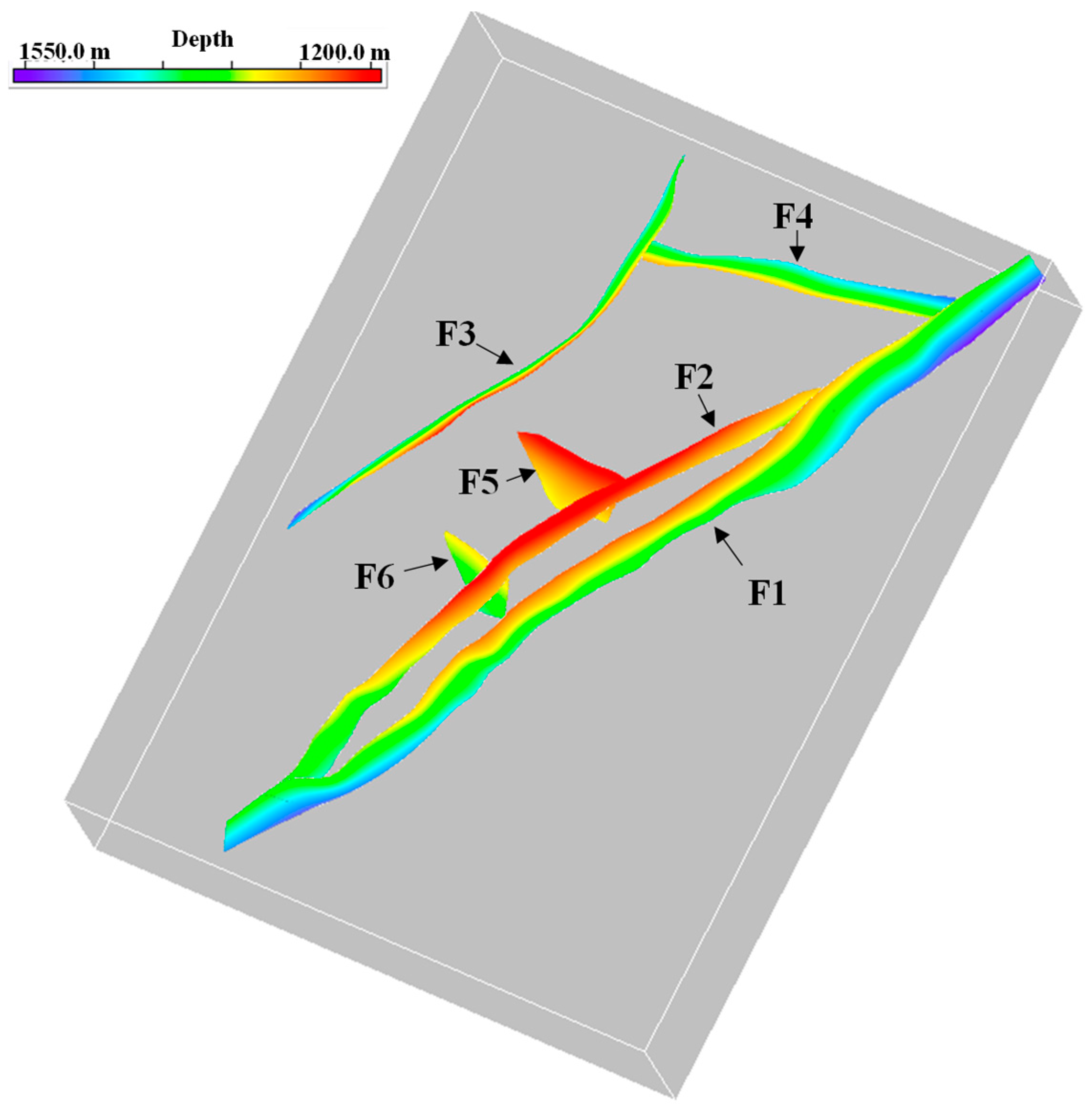
2.2.1. Geometric Features

The trap-scale structural interpretations of the gas storage are based on high-quality 3D seismic data, which can be used for detailed structure interpretation and throw determination. In addition, well data, including production test reports and wireline log data, are provided. Well wireline logs and production test reports were used to identify lithologies and gas types. The structural geometric elements of the boundary fault, as derived from the seismic interpretation data, are shown in Table 1.

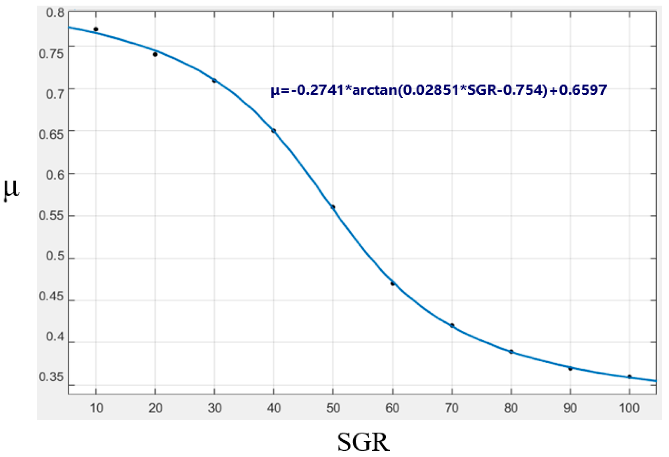
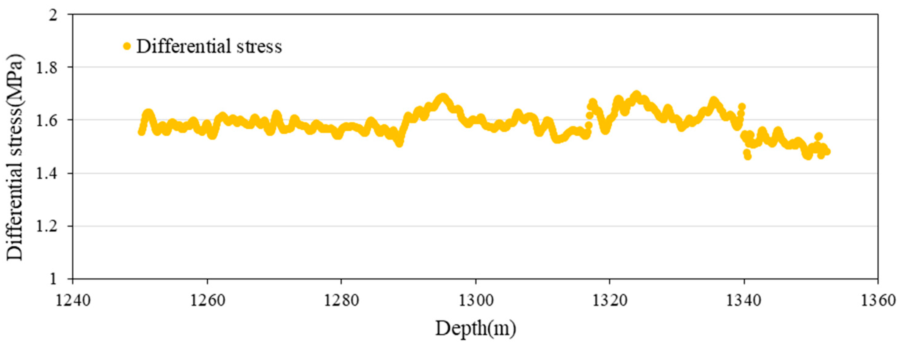
2.2.2. Characterization Data of the Friction Coefficient of Fault Rock

The X-ray Diffraction (XRD) clay mineral analysis data were analyzed to characterize the heterogeneity of cross-sectional friction strength, as detailed in Section 4.2. The data are from Well Lei X—6, within a depth range of 1341.09 to 1391.77 m (Table 2). The main types of clay minerals identified include illite mixed layer, illite, kaolinite, and chlorite. By converting the illite mixed layer into illite and montmorillonite based on the mixing ratio, the following proportions of various clay minerals were determined: approximately 28.3% illite, 51.6% montmorillonite, 12.2% kaolinite, and 7.9% chlorite.

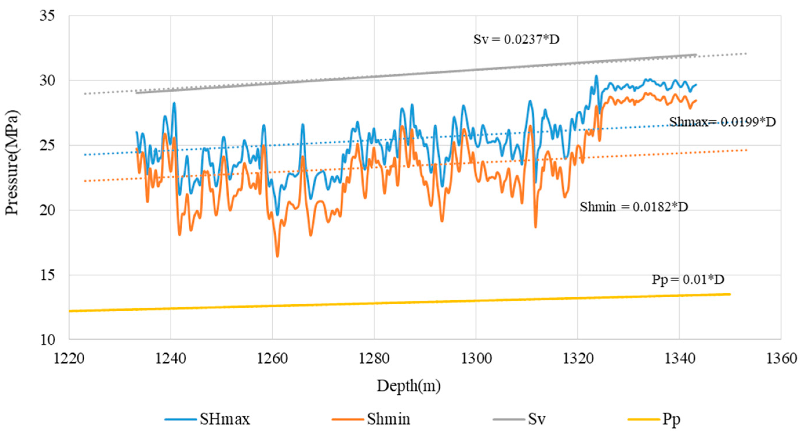
2.3. Determination of the In-Situ Stress

The in-situ stress can be expressed by the vertical stress, maximum horizontal principal stress, and minimum horizontal principal stress under the ground. In addition, their effective stresses are related to pore fluid pressure. Due to the absence of overpressure characteristics in the region, the pore fluid pressure primarily consists of static water pressure. In this study, vertical stress was determined using the density logging curve (Equation (1)). Horizontal stress was calculated by analyzing X-mac rock mechanics logging data from Well Lei X-2 and constructing a geostress data relationship chart (Figure 2) specific to the study area. The orientation of geostress was predominantly established through cross-dipole array sonic logging data, confirming that the direction of maximum horizontal principal stress in the study area was N97°.
S v = ρ w g h w + h w h ρ h g d h

3. Materials and Methods

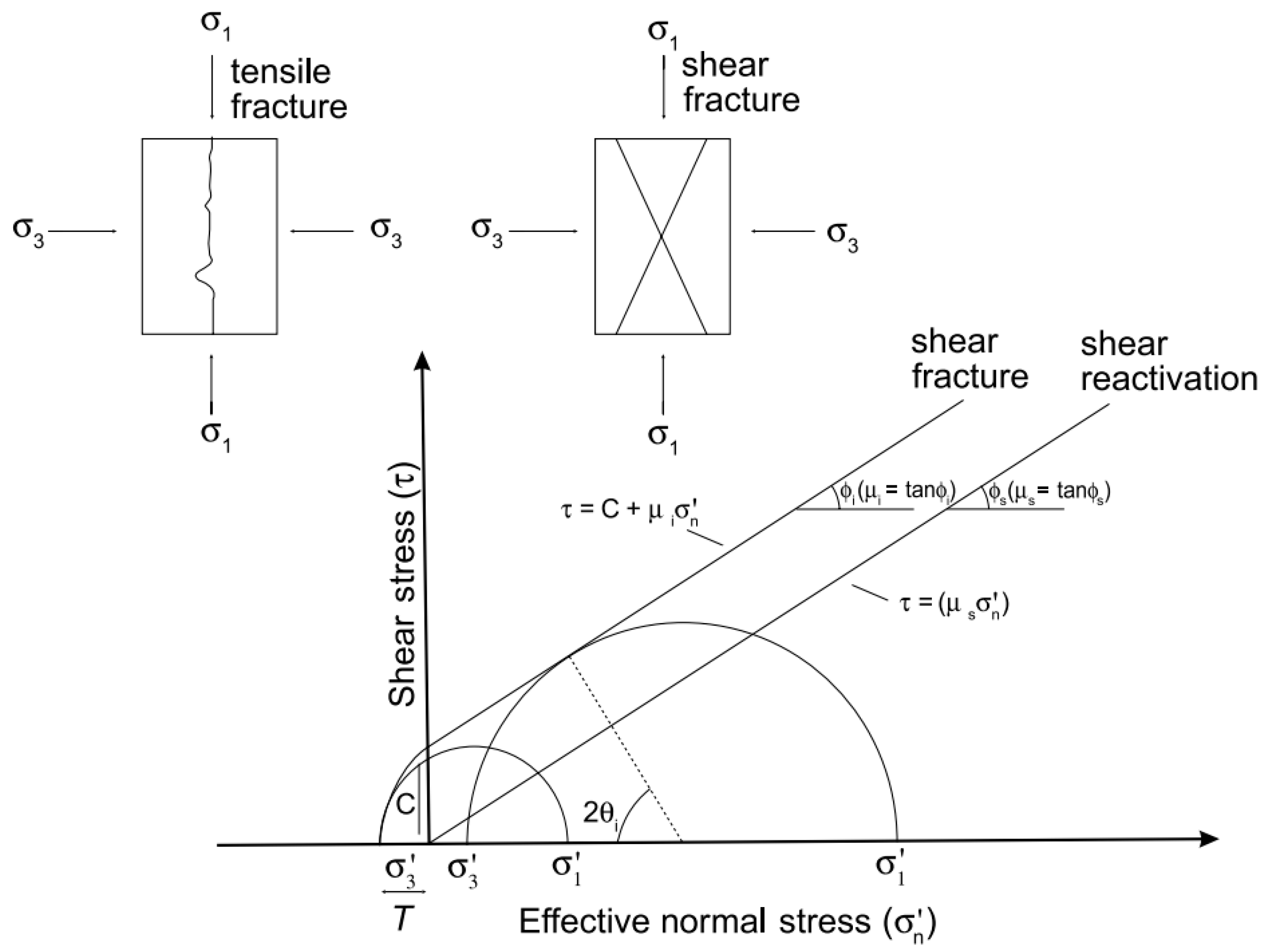
3.1. Method for Evaluating Activation Pressure in Boundary Faults

Currently, there are several methods available for assessing fault stability, with the key parameters including stress, formation pressure, fault dip, the friction coefficient, and cohesion of the fault. Due to the challenging nature of accurately describing fault cohesion and its typically small impact in shallow layers, we opted for the relatively conservative CPP (Critical Pressure Perturbation) method for evaluating fault stability by disregarding the cohesion of the fault (as indicated by the dashed contour line in Figure 3). As fluid pressure increases, the Mohr circle shifts leftward until it intersects with the failure envelope line; this movement distance represents the maximum pressure that can be sustained by the fault. The activation pressure denotes the total pressure that a fault can withstand and is mathematically expressed in Equation (2).
P R = S n τ / μ
where, PR is the activation pressure for faults, MPa. Sn is the normal stress on the fault, MPa. τ is the shear stress on the fault, MPa. μ is the friction coefficient of the fault, which is dimensionless.
Additional fluid pressure refers to the extra pressure that can be tolerated under current strain and geological conditions, as defined in Equation (3).
P = P R P P
where, ∆P is the fault additional fluid pressure, MPa. PP is the formation pressure, MPa.
Based on the results of the stress field evaluation, the shear stress and effective normal stress in the section can be quantitatively decomposed into the three principal stresses and the geometric characteristics of the fault using Equations (4) and (5).
σ n = σ 1 cos 2 α n + σ 2 c o s 2 β n + σ 3 c o s 2 γ n
τ = σ 1 2 cos 2 α n + σ 2 2 c o s 2 β n + σ 3 2 c o s 2 γ n σ n 2
where, σ 1 is the vertical principal stress, MPa. σ 2 and σ 3 are the maximum and minimum horizontal principal stresses, respectively, MPa. α n ,   β n ,   a n d   γ n are the angles between the three-way principal stress and the normal direction of the cross-section, °.

3.2. Evaluation Method for Heterogeneity of Friction Coefficient on Fault Surfaces

This study revealed a significant association between clay content and the friction coefficient [27]. Subsequent studies by Logan and Rauenzahn (1987) [28], Saffer and Marone (2003) [29], Tembe et al. (2010) [30], Eijsink et al. (2022) [31], and Abdelaziz et al. (2023) [32] further support this finding. Specifically, an increase in clay content corresponds to a decrease in the friction coefficient, suggesting a heightened risk of activity in fault zones with high clay content, which warrants attention. Building upon prior research into the correlation between high-purity clay minerals and the friction coefficient, a volume-weighted analysis was employed to investigate the relationship between the friction coefficient and clay content within the study area. Detailed percentages of the different clay minerals are provided in Section 2.2. The results are depicted in Figure 4. To represent the non-uniformity of sectional friction coefficients using data from Figure 4, it is essential to first simulate and calculate the section’s clay content, commonly achieved through the application of the SGR algorithm as proposed by Yielding (2002).
S G R = V s h · Z D × 100 %
where, ΔZ is the formation thickness, m. Vsh is the mud content of the formation, %. D is the break distance, m.

3.3. Evaluation Method of Cap Rock Fracture Pressure

The brittle fracture of rocks is governed by the Griffith–Coulomb fracture criterion (represented by the solid line in the failure envelope in Figure 3). The fracture pattern of rocks is contingent upon the relative size of the differential stress ΔS (σ1σ3) and the tensile strength T of the rock body (Table 3), leading to distinct fracture patterns under varying critical conditions. Specifically, when ΔS < 4T, tensile fractures occur. When 4T < ΔS < 6T, a combination of tensile and shear fractures takes place. When ΔS > 6T, shear fractures ensue (Table 3). Consequently, this study necessitates initial determination of the overburden stress field and tensile strength through evaluation results, followed by the selection of a suitable expression for the hydraulic fracturing numerical analysis of the overburden (Table 3).

4. Results and Discussion

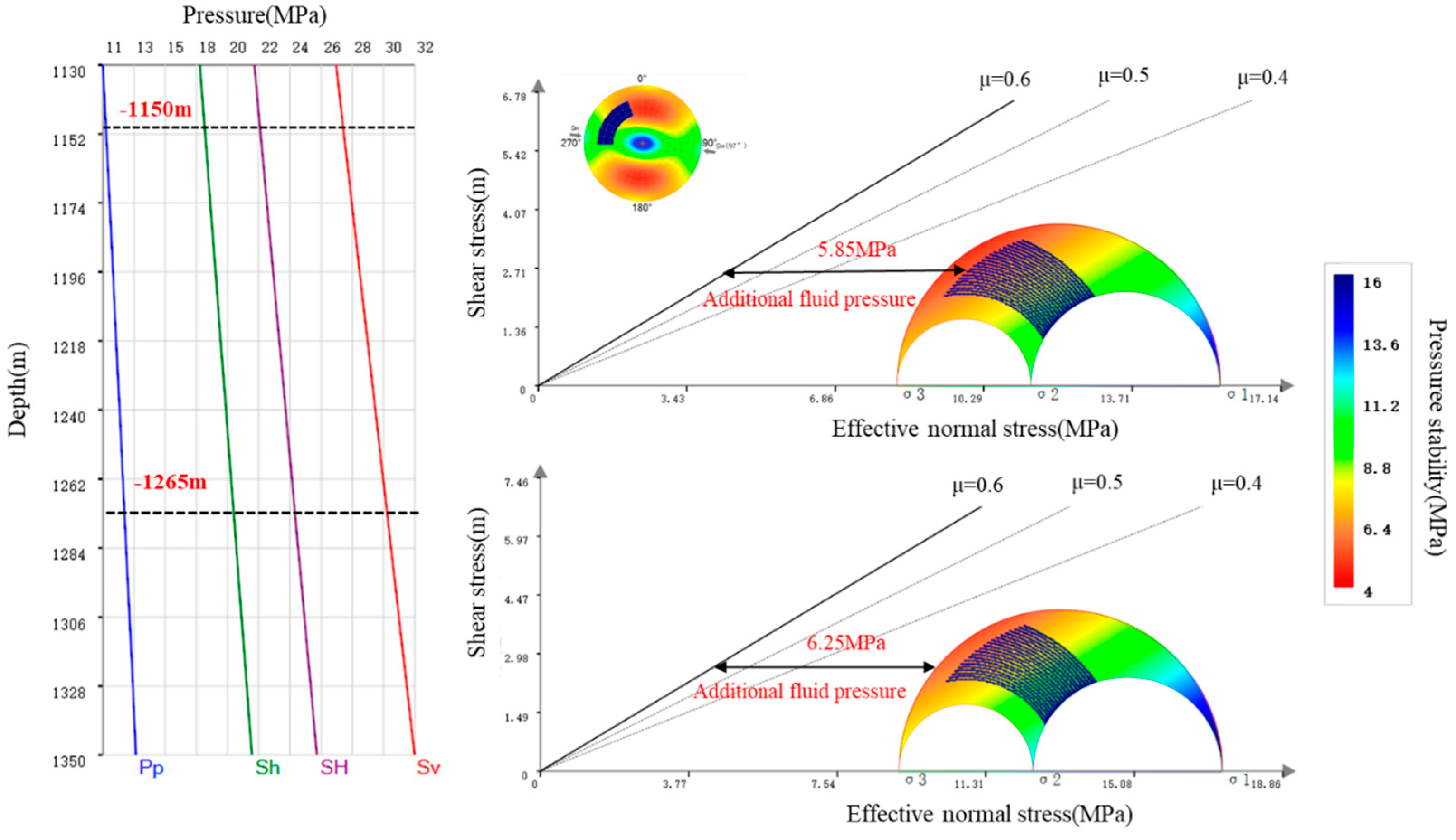
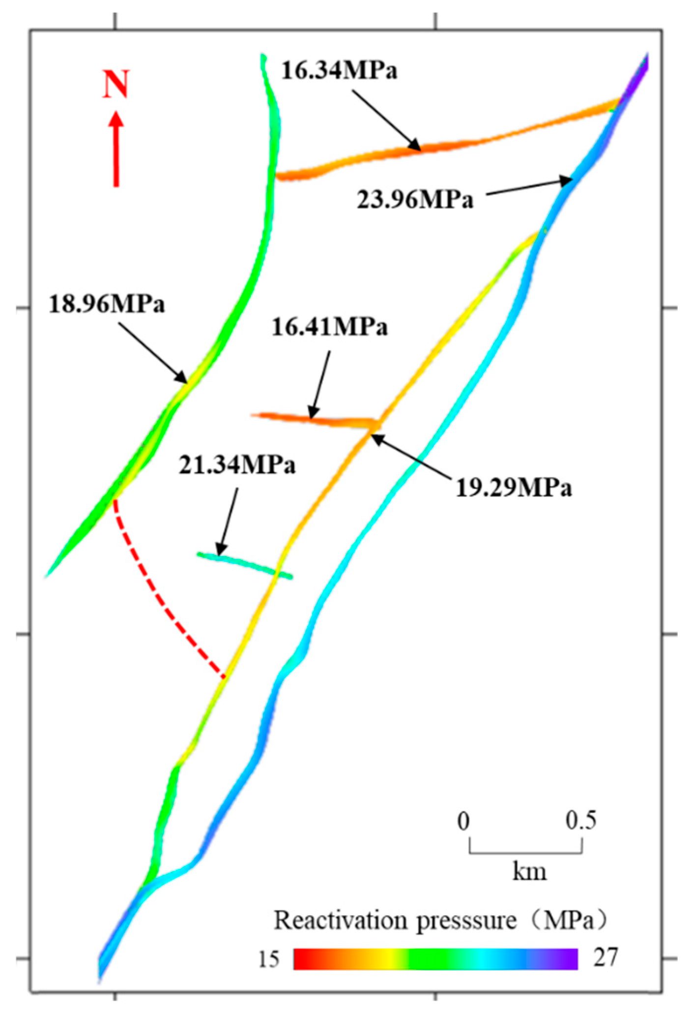
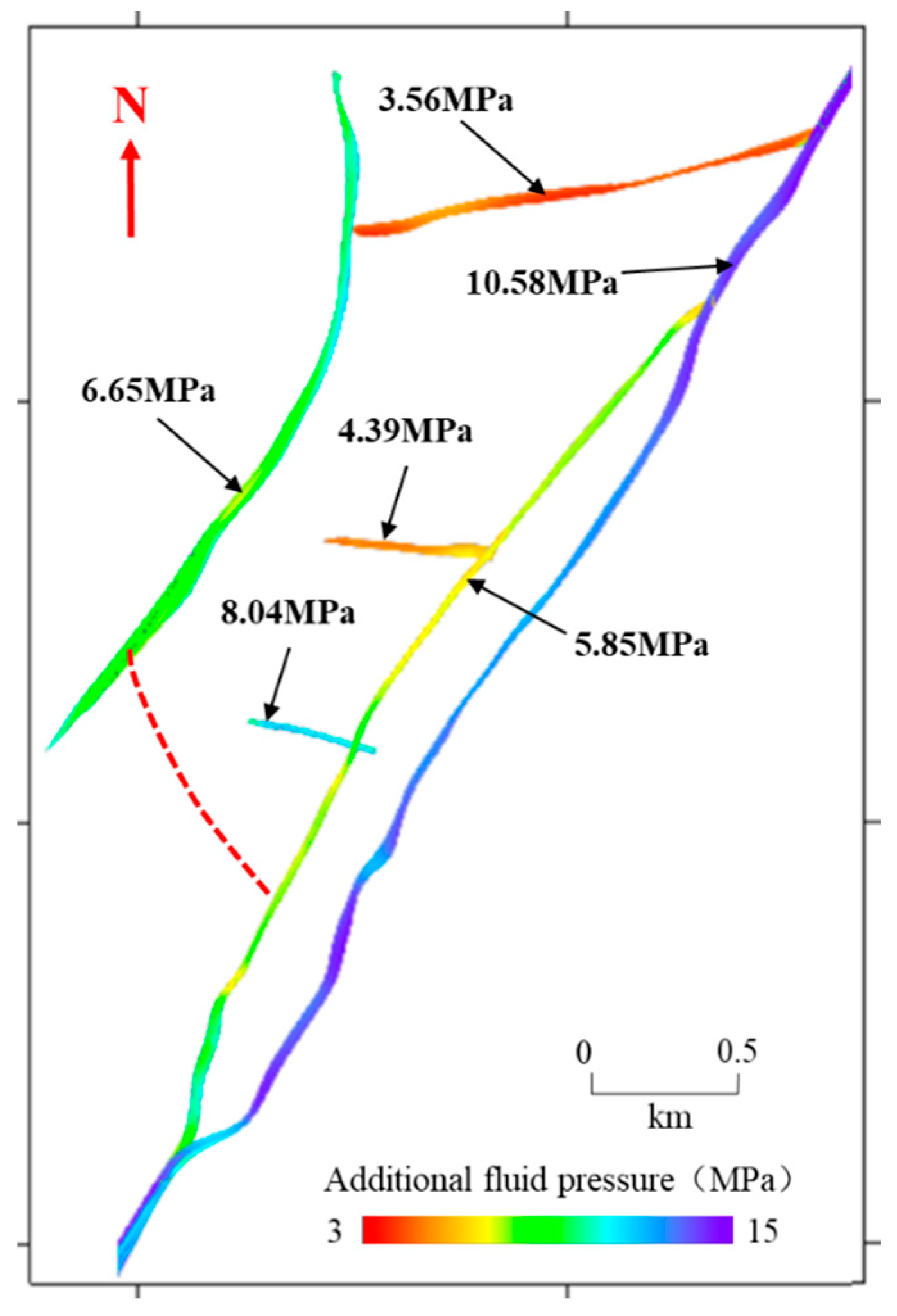
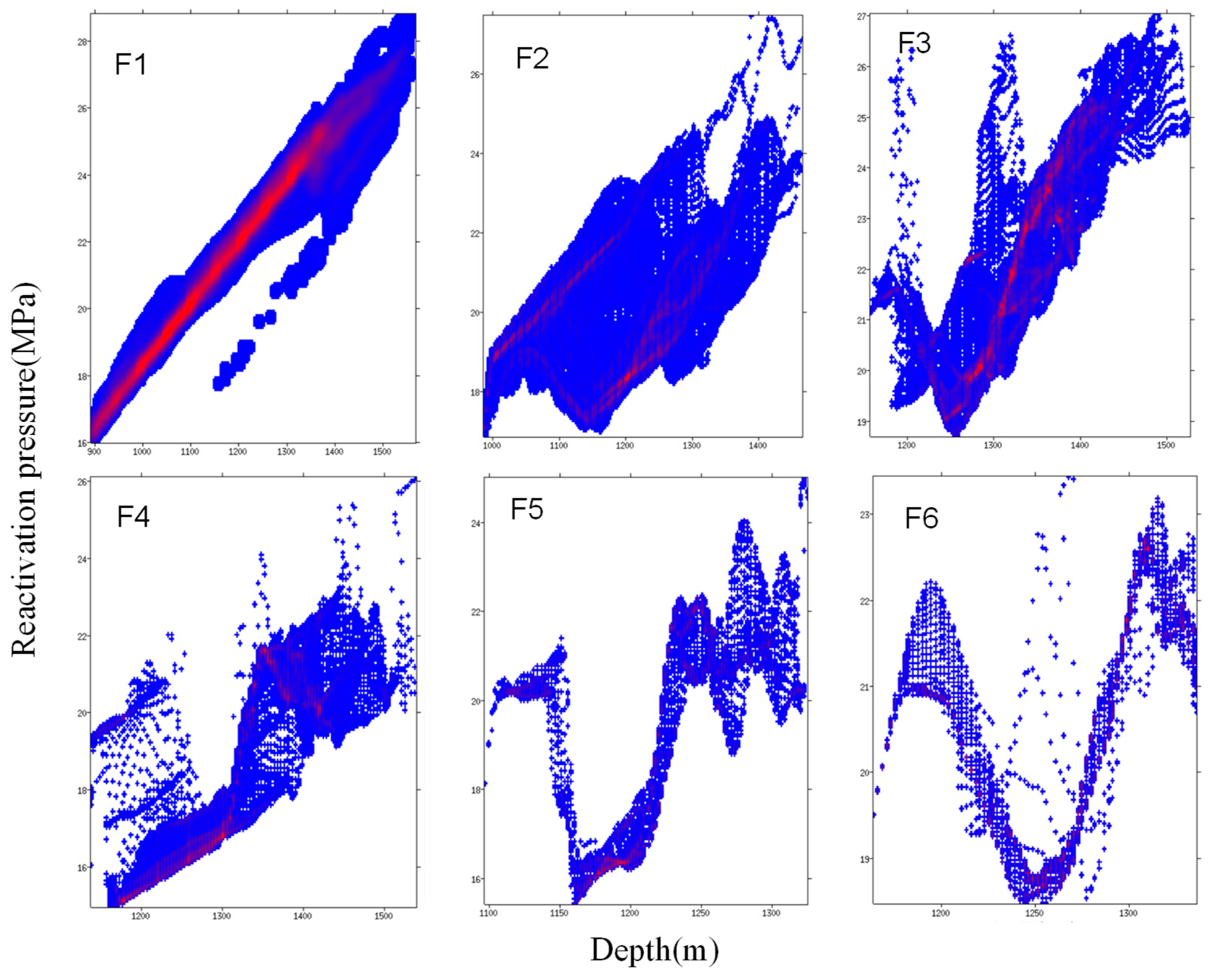
4.1. Activation Pressure of Boundary Faults

Based on the stress field data, a 2D assessment map of F2 fault stability was established (Figure 5). From Figure 5, it is evident that under static water pressure conditions, the optimal orientation of the F2 fault surface was at a depth of −1150 m with an additional fluid pressure of 8.1 MPa. The optimal orientation of the fault surface perpendicular to the fault was at a depth of −1265 m with an additional fluid pressure of 10.3 MPa, indicating that the stability of the fault is influenced by its dip.
The control range of the reservoir section within the Lei X gas storage facility was influenced by faults F1, F2, F3, and F4. Among these, the control range segment of the F1 fault was relatively smaller, whereas the entire extent of the F4 fault fell within this segment. Statistical analysis of the effective activation pressure for each fault within the reservoir section (Figure 6) indicates that the lowest activation pressure overall occurred at the F4 fault, measuring 16.34 MPa. The minimum activation pressures for the other faults were as follows: F1 fault at 23.96 MPa, F2 fault at 19.29 MPa, and F3 fault at 18.96 MPa. Additionally, new findings reveal that faults -F5 and -F6 have values of 16.41 MPa and 21.34 MPa, respectively. It can be concluded that among all the faults in this area, fault -F4 exhibits a notably low activation pressure of 43.2 MPa and is associated with planar risk (Figure 7).
Based on the pressure activation data of each stratum and fault in the Lei X gas storage reservoir, as illustrated in Figure 8, it can be inferred that the F4 fault within the inner control ring exhibits a minimum activation pressure of 16.34 MPa and a minimum additional fluid pressure of 3.27 MPa. This indicates relatively weak stability for the F4 fault in the Lei X gas storage reservoir, rendering it more susceptible to activity compared to other faults.

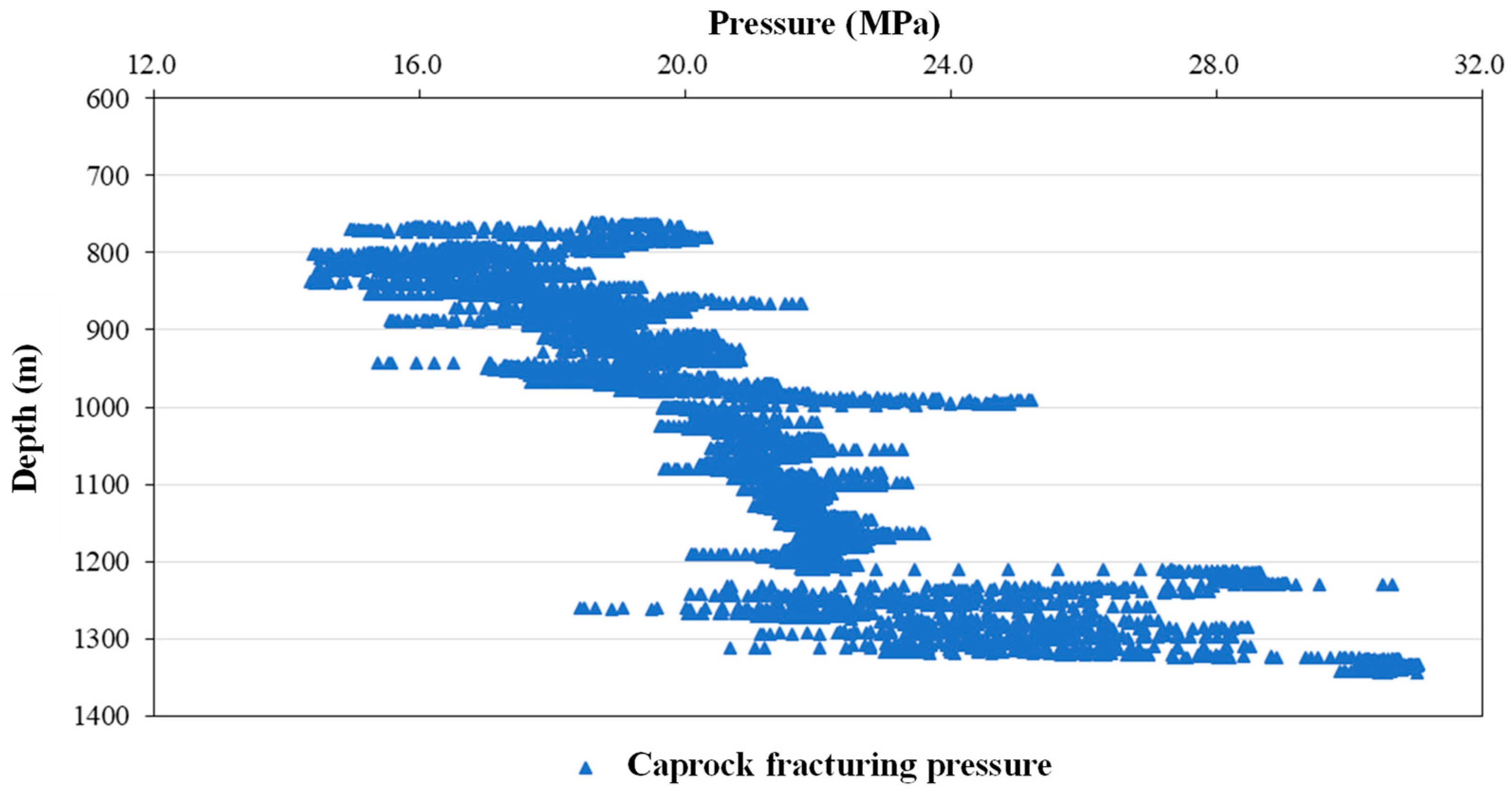
4.2. Calculating the Upper Limit of Hydraulic Fracturing Pressure for Gas Storage Cap Layers

Based on the analysis of the stress field, we established the relationship between differential stress and depth (Figure 9). The differential stress in the overburden layer ranged from 1.5 to 1.7 MPa, whereas the average tensile strength T of the overburden was 2.0 MPa. In other words, (σ1σ3) < 4T. Through comparison, it can be inferred that the rock fracture mode is tensile fracture, specifically hydraulic fracture.
The risk assessment for hydraulic fracturing in the formation utilizes the holding force method, where the hydraulic fracturing pressure (PHF) is determined as the sum of the rock’s tensile strength and the minimum horizontal principal stress (PHF = T + σ3). Based on the aforementioned analysis method, the pressure profile of rock fracturing under hydraulic pressure at various depths was derived (Figure 10). As depicted in Figure 10, it is evident that the minimum pressure required for overburden rock fracturing was 14.4 MPa at the top of the overburden, increasing to 16.5 MPa at the bottom where it interfaces directly with the reservoir. Further scrutiny reveals distinct stress conditions across different depths, with a comparative assessment indicating a gradual increase in rock stress with depth. These findings have significant implications for engineering design and practical construction.

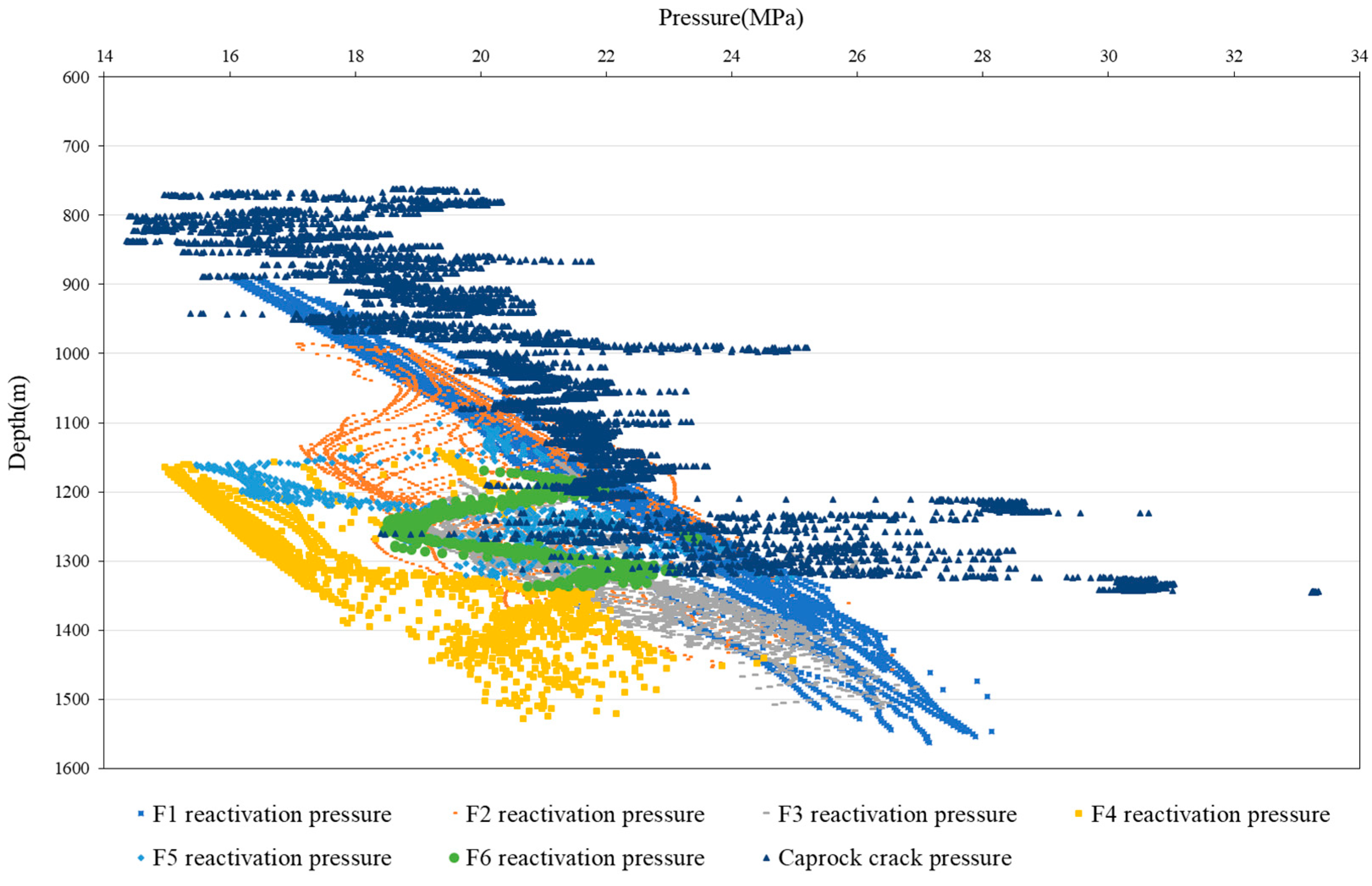
4.3. Calculating the Upper Limit of Safe Operating Pressure for Gas Storage Facilities

Based on research findings regarding fault activation and cap rock hydraulic fracturing risk, a model for evaluating the upper limit of safe operating pressure was developed for the Lei X gas storage facility (Figure 11). In accordance with the safety operation pressure upper limit evaluation system of the gas storage facility, it is essential to conduct a comprehensive analysis of cap rock hydraulic fracturing pressure and fault activation pressure within the specified depth range. The shallowest burial depth of the target gas stratum is −1000 m, and the maximum depth of the base is −1500 m. Therefore, when determining the operational pressure within the gas storage facility, it is crucial to consider both the comprehensive gas storage depth and the water–gas interface.
To ensure the stability of the gas reservoir’s faults, once the operational pressure reaches 15 MPa, fault F4 is activated at a depth of −1150 m. Subsequently, at 15.48 MPa, activation occurs for fault F5, which is located nearby. Although this does not risk natural gas seepage, it poses other geological hazards. Adhering to these principles, the minimum activation pressures and depths for each fault within the storage are as follows: faults F1 (18 MPa, −1005 m), F2 (17.55 MPa, −1000 m), F3 (19.55 MPa, −1185 m), and F6 (18.50 MPa, −1261 m). The base-depth for cap rock stands at −1000 m, making activation pressures here crucial. According to our assessment model, the minimum breaking point for cap rock lies at a pressure of 19.7 MPa, occurring at a depth of −1000 m.
Based on the number of risk types, safety risks associated with gas storage facilities can be categorized into three zones based on the upper limit pressure. The first zone is the risk-free zone, where no safety risks exist when the pressure inside the gas storage facility is below 15 MPa. The second zone is the low-risk zone, where potential safety hazards may arise due to the activation of boundary faults at pressure levels between 15.0 and 19.7 MPa. The third zone is the high-risk zone, where pressure levels above 19.7 MPa may not only activate internal faults of the gas storage facility but also potentially cause rupture of the top cap layer, leading to serious issues. Based on a comprehensive evaluation of the results and various potential hazard factors, it is recommended that the upper limit pressure for gas storage facilities should not exceed 15.0 MPa to ensure safety. This measure can effectively reduce the likelihood of potential accidents and provide a more reliable and stable operating environment. Additionally, it is essential to closely monitor and timely adjust relevant parameters to maintain optimal system conditions and take necessary measures to ensure facility and personnel safety in case of emergencies.

4.4. Discussion

Based on the evaluation model above, the shallowest burial depth of the gas storage was −1000 m, corresponding to a minimum fracture pressure of 19.7 MPa for the overburden. However, during actual gas storage operations, particular attention should be given to the stability and connectivity of the overburden rock. Exceeding a certain threshold in internal operating pressure may activate existing fractures in the overburden rock, leading to leakage risk. In such cases, rock fracture connectivity becomes a critical factor. In addition to considering the connectivity and stability of overburden rock fractures, other influencing factors, such as changes in groundwater levels and seismic activity, should also be thoroughly researched. These factors could impact the overburden rock and exacerbate leakage risks under high-pressure conditions. Therefore, when designing and constructing gas storage facilities, it is crucial to fully consider the surrounding environmental conditions and geological structure characteristics while implementing appropriate measures to prevent serious leakage under high-pressure conditions.
Based on geological exploration data, the F4 fault occupies a critical position in the selection of a gas storage site, and its stability significantly influences the safe operation of the gas storage facility. In addition to current stress field characteristics, other factors such as rock properties, structural features, and potential slip surfaces of the fault must also be taken into account. A comprehensive analysis of these factors will enable a more accurate assessment of the potential risks associated with F4 fault activity and provide a scientific basis for gas storage site selection. Furthermore, when determining the depth and geometric characteristics of the boundary fault, careful consideration should be given to the surrounding geological environment and tectonic background. This includes identifying any other structural bodies that interact with or are subjected to similar stress as the F4 fault. Attention should also be paid to local seismic activity and historical geological disaster events in similar areas. These considerations will facilitate a comprehensive and systematic evaluation of the possible impact of the boundary fault on the safe operation of gas storage facilities. In conclusion, during gas storage site selection, all relevant factors must be fully integrated, and scientific and effective measures should be implemented to mitigate potential risks associated with boundary faults in order to ensure long-term stable and safe operations at gas storage facilities.

5. Conclusions

(1) By employing the method of fault activation pressure assessment, a comprehensive evaluation of the stability of faults comprising the underground gas storage facility was conducted. Within each control ring of the Lei X gas storage facility, it was found that the F4 fault exhibited an activation pressure coefficient of 1.27, indicating relatively weak stability and susceptibility to activity. Conversely, all other control ring faults demonstrated activation pressure coefficients exceeding 1.43, signifying robust stability and a greater capacity to withstand pressure.
(2) Based on a comprehensive evaluation of hydraulic fracturing and fault instability in the overburden, the upper limit operating pressure of the gas storage facility was categorized into three risk pressure zones. It is recommended to maintain the upper limit operating pressure within the risk-free range, i.e., below 15.0 MPa, to ensure safe and stable operation of the facility while minimizing potential safety hazards.
(3) By conducting a comprehensive analysis of underground rock structures and stress distribution, the stability and safety of gas storage facilities can be more accurately evaluated under various operating conditions. The method for calculating the activation pressure of boundary faults in the gas storage cover can be utilized to assess the risk of cover fault activation, as well as to determine the activation pressure and critical water pressure fracture pressure of each fault during cyclic injection and production processes. When determining the safe operating pressure of the gas reservoir in a gas storage facility, it is essential to consider various factors such as geological conditions, injection and production operation methods, and environmental impact. Only by fully considering these factors and integrating advanced monitoring technologies with data analysis methods can we effectively enhance the safety and reliability of the injection and production processes at gas storage facilities. Scientifically determining the safe operating pressure for a gas reservoir in a gas storage facility is crucial for ensuring its long-term stable operation, making it worthwhile to study and promote.

Author Contributions

X.C. and L.M.: writing—original draft, writing—review and editing, project administration, and conceptualization. T.Z.: conceptualization, funding acquisition, and project administration. H.W.: resources, data curation, formal analysis, and methodology. Y.J.: visualization, validation, methodology, investigation, formal analysis, and data curation. All authors have read and agreed to the published version of the manuscript.

Funding

This research received no external funding.

Data Availability Statement

All data, models, or code generated or used during this study are available from the corresponding author by request.

Acknowledgments

The authors are grateful to FAPS Energy Technology Ltd. (www.faps.com.cn) for the use of FAPSeal 3D software.

Conflicts of Interest

Xianxue Chen, Tianguang Zhang and Haibo Wen were employed by the Liaohe Oilfield Branch Gas Storage Company of PetroChina. The remaining authors declare that the research was conducted in the absence of any commercial or financial relationships that could be construed as a potential conflict of interest.

References

  1. Xu, C.; Xie, Z.; Kang, Y.; Yu, G.; You, Z.; You, L.; Zhang, J.; Yan, X. A novel material evaluation method for lost circulation control and formation damage prevention in deep fractured tight reservoir. Energy 2020, 210, 118574. [Google Scholar] [CrossRef]
  2. Li, S.; Fan, Y.; Guo, Y.; Wang, Y.; He, T.; Zhang, H.; Ye, J.; Chen, W.; Zhang, X. Simulation and control strategies for longitudinal propagation of acid fracture in a low-permeability reservoir containing bottom water. Processes 2024, 12, 792. [Google Scholar] [CrossRef]
  3. Khurshid, I.; Afgan, I. Geochemical investigation of CO2 injection in oil and gas reservoirs of middle east to estimate the formation damage and related oil recovery. Energies 2021, 14, 7676. [Google Scholar] [CrossRef]
  4. Inaolaji, A.; Wu, X.; Roychowdhury, R.; Smith, R. Optimal allocation of battery energy storage systems for peak shaving and reliability enhancement in distribution systems. J. Energy Storage 2024, 95, 112305. [Google Scholar] [CrossRef]
  5. Xu, C.Y.; Xie, J.; Kang, Y.L.; Liu, L.; Guo, K.; Xue, D.; You, Z.J. Fracture pre-propping and temporary plugging for formation damage control in deep naturally fractured tight reservoirs. SPE J. 2024, 27, 1–16. [Google Scholar] [CrossRef]
  6. Mahjour, S.K.; Faroughi, S.A. Risks and uncertainties in carbon capture, transport, and storage projects: A comprehensive review. Gas Sci. Eng. 2023, 119, 205117. [Google Scholar] [CrossRef]
  7. Xu, W.; Zhao, P.; Gou, F.; Wu, W.; Liu, A.; Wang, J. A combined heating and power system based on compressed carbon dioxide energy storage with carbon capture: Exploring the technical potential. Energy Convers. Manag. 2022, 260, 115610. [Google Scholar] [CrossRef]
  8. Mortezaei, K.; Amirlatifi, A.; Ghazanfari, E.; Vahedifard, F. Potential CO2 leakage from geological storage sites: Advances and challenges. Environ. Geotech. 2021, 8, 3–27. [Google Scholar] [CrossRef]
  9. Eigbe, P.A.; Ajayi, O.O.; Olakoyejo, O.T.; Fadipe, O.L.; Efe, S.; Adelaja, A.O. A general review of CO2 sequestration in underground geological formations and assessment of depleted hydrocarbon reservoirs in the Niger Delta. Appl. Energy 2023, 350, 121723. [Google Scholar] [CrossRef]
  10. Morris, A.; Ferrill, D.A.; Henderson, D.B. Slip-tendency analysis and fault reactivation. Geology 1996, 24, 275–278. [Google Scholar] [CrossRef]
  11. Ferrill, D.A. Stressed rock strains groundwater at Yucca Mountain, Nevada. GSA Today 1999, 9, 1–8. [Google Scholar]
  12. Castillo, D.A.; Bishop, D.J.; Donaldson, I.; Kuek, D.; De Ruig, M.; Trupp, M.; Shuster, M.W. Trap integrity in the Lam in Aria High-Nancar trough region, Timor Sea: Prediction of fault seal failure using well-constrained stress tensors and fault surfaces interpreted from 3D seismic. APPEA J. 2000, 40, 151–173. [Google Scholar] [CrossRef]
  13. Wiprut, D.; Zoback, M.D. Fault reactivation, leakage potential, and hydrocarbon column heights in the northern North Sea. In Norwegian Petroleum Society Special Publications; Elsevier: Amsterdam, The Netherlands, 2002; Volume 11, pp. 203–219. [Google Scholar]
  14. Gholami, R.; Raza, A.; Iglauer, S. Leakage risk assessment of a CO2 storage site: A review. Earth-Sci. Rev. 2021, 223, 103849. [Google Scholar] [CrossRef]
  15. Tenthorey, E.; Dance, T.; Cinar, Y.; Ennis-King, J.; Strand, J. Fault modelling and geomechanical integrity associated with the CO2CRC Otway 2C injection experiment. Int. J. Greenh. Gas Control 2014, 30, 72–85. [Google Scholar] [CrossRef]
  16. Meng, L.; Fu, X.; Lv, Y.; Li, X.; Cheng, Y.; Li, T.Y. Risking fault reactivation induced by gas injection into depleted reservoirs based on the heterogeneity of geomechanical properties of fault zones. Pet. Geosci. 2016, 23, 29–38. [Google Scholar] [CrossRef]
  17. Taghipour, M.; Ghafoori, M.; Lashkaripour, G.R.; Hafezi Moghaddas, N.; Molaghab, A. Estimation of the current stress field and fault reactivation analysis in the Asmari reservoir, SW Iran. Pet. Sci. 2019, 16, 513–526. [Google Scholar] [CrossRef]
  18. Roberts, S.J.; Nunn, J.A. Episodic fluid expulsion from geopressured sediments. Mar. Pet. Geol. 1995, 12, 195–204. [Google Scholar] [CrossRef]
  19. Ungerer, P.; Burrus, J.; Doligez, B.P.; Chenet, P.Y.; Bessis, F. Basin evaluation by integrated two-dimensional modeling of heat transfer, fluid flow, hydrocarbon generation, and migration. AAPG Bull. 1990, 74, 309–335. [Google Scholar]
  20. Jin, Y.J.; Fan, C.; Fu, X.; Meng, L.; Liu, B.; Jia, R.; Cao, S.; Du, R.; Li, H.; Tan, J. Risk analysis of natural hydraulic fracturing in an overpressured basin with mud diapirs: A case study from the Yinggehai Basin, South China sea. J. Pet. Sci. Eng. 2021, 196, 107621. [Google Scholar] [CrossRef]
  21. Kearney, L.M.; MacMinn, C.W.; Katz, R.F.; Kirkham, C.; Cartwright, J. Episodic, compression-driven fluid venting in layered sedimentary basins. Proc. R. Soc. A 2023, 479, 20220654. [Google Scholar] [CrossRef]
  22. Hu, T.; Pang, X.; Jiang, F.; Wang, Q.; Liu, X.; Wang, Z.; Jiang, S.; Wu, G.; Li, C.; Xu, T.; et al. Movable oil content evaluation of lacustrine organic-rich shales: Methods and a novel quantitative evaluation model. Earth-Sci. Rev. 2021, 214, 103545. [Google Scholar] [CrossRef]
  23. Zhou, L.; Zheng, X.; Lu, Y.; Li, H.; Feng, M. Fracture pattern and caprock integrity analyses via hydraulic fracturing for CO2 enhanced coal bed methane. Eng. Fract. Mech. 2020, 228, 106894. [Google Scholar] [CrossRef]
  24. Li, S.; Fan, Y.; Wang, Y.; Zhao, Y.; Lv, Z.; Ji, Z.; Chen, W.; Min, J. True triaxial physics simulations and process tests of hydraulic fracturing in the Da’anzhai section of the Sichuan Basin tight oil reservoir. Front. Energy Res. 2023, 11, 1267782. [Google Scholar] [CrossRef]
  25. Chang, X.; Xu, E.; Guo, Y.; Yang, C.; Hu, Z.; Guo, W. Experimental study of hydraulic fracture initiation and propagation in deep shale with different injection methods. J. Pet. Sci. Eng. 2022, 216, 110834. [Google Scholar] [CrossRef]
  26. Dahrabou, A.; Valley, B.; Meier, P.; Brunner, P.; Alcolea, A. A systematic methodology to calibrate wellbore failure models, estimate the in-situ stress tensor and evaluate wellbore cross-sectional geometry. Int. J. Rock Mech. Min. Sci. 2022, 149, 104935. [Google Scholar] [CrossRef]
  27. Shimamoto, T.; Logan, J.M. Effects of simulated clay gouges on the sliding behavior of Tennessee sandstone. Tectonophysics 1981, 75, 243–255. [Google Scholar] [CrossRef]
  28. Logan, J.M.; Rauenzahn, K.A. Frictional dependence of gouge mixtures of quartz and montmorillonite on velocity, composition and fabric. Tectonophysics 1987, 144, 87–108. [Google Scholar] [CrossRef]
  29. Saffer, D.M.; Marone, C. Comparison of smectite-and illite-rich gouge frictional properties: Application to the updip limit of the seismogenic zone along subduction megathrusts. Earth Planet. Sci. Lett. 2003, 215, 219–235. [Google Scholar] [CrossRef]
  30. Tembe, S.; Lockner, D.A.; Wong, T.F. Effect of clay content and mineralogy on frictional sliding behavior of simulated gouges: Binary and ternary mixtures of quartz, illite, and montmorillonite. J. Geophys. Res. Solid Earth 2010, 115, B03416. [Google Scholar] [CrossRef]
  31. Eijsink, A.M.; Kirkpatrick, J.D.; Renard, F.; Ikari, M.J. Fault surface morphology as an indicator for earthquake nucleation potential. Geology 2022, 50, 1356–1360. [Google Scholar] [CrossRef]
  32. Abdelaziz, A.; Ha, J.; Li, M.; Magsipoc, E.; Sun, L.; Grasselli, G. Understanding hydraulic fracture mechanisms: From the laboratory to numerical modelling. Adv. Geo-Energy Res. 2023, 7, 66–68. [Google Scholar] [CrossRef]
Figure 1. Simulation results of the 3D structure and shape of the Lei X gas storage facility.
Processes 12 01910 g001
Figure 2. Three-dimensional principal stress and pore pressure evaluation map for gas storage reservoirs.
Processes 12 01910 g002
Figure 3. Mechanism of complete rock fracture and reactivation of pre-existing faults/fractures.
Processes 12 01910 g003
Figure 4. Relationship between the friction coefficient and shale content (SGR) of fault rocks in the study area.
Processes 12 01910 g004
Figure 5. Stereoscopic projection of fault stability at different depths of the F2 fault (depths of 1150–1265 m).
Processes 12 01910 g005
Figure 6. Plane distribution of fault activation pressure in the S3I-1 layer of the Lei X gas storage.
Processes 12 01910 g006
Figure 7. Plane distribution of additional fluid pressure on the fault in the S3 I-1 layer of the Lei X gas storage reservoir.
Processes 12 01910 g007
Figure 8. Statistical data on activation pressure for various boundary faults at different depths.
Processes 12 01910 g008
Figure 9. Fitting curve of the relationship between differential stress and depth in the formation.
Processes 12 01910 g009
Figure 10. Hydraulic fracturing pressure profile of formation rocks.
Processes 12 01910 g010
Figure 11. Evaluation template for the upper limit of safe operating pressure for the Lei X gas storage facility.
Processes 12 01910 g011
Table 1. Statistics of the geometric characteristic parameters of the boundary faults.
FaultF1F2F3F4F5F6
Depth (m)1524–21001160–12801285–15851440–16001185–12401210–1445
Dip (°)65.155.559.358.638.435.8
Strike (°)212.5213.331.779.3277.4287.5
Table 2. XRD clay mineral analysis test data.
Sample No.Well Depth
/m
The Proportion of Different Types of Clay Minerals/%Ratio of Imon Mixed Layer
Imon Mixed LayerIlliteKaoliniteChlorite
113414229151473
213454823151479
313475723101071
413485822101071
5134962238776
613544033141356
7135575155586
8135671166786
9135865217788
10136871138890
1113718276596
12137272185595
13138177107694
1413848096596
15139161238868
Table 3. Failure modes of cap rock and risk assessment methods under different failure modes.
Fracture ModeRock Fracture CriterionStress Conditions
Tensile rupture (hydraulic rupture)P = σ3 + T(σ1σ3) < 4T
Mixed rupture of tension and shearP = σn + (4T2τ2)/4T4T < (σ1σ3) < 6T
Shear fractureP = σn + (Cτ)/μ(σ1σ3) > 6T
Disclaimer/Publisher’s Note: The statements, opinions and data contained in all publications are solely those of the individual author(s) and contributor(s) and not of MDPI and/or the editor(s). MDPI and/or the editor(s) disclaim responsibility for any injury to people or property resulting from any ideas, methods, instructions or products referred to in the content.

