Article

Experimental Investigation and Numerical Validation of a Roots Pump’s Performance Operating with Gas-Liquid Mixtures

1
School of Marine Science and Technology, Northwestern Polytechnical University, Xi’an 710072, China
2
Xi’an Precision Machinery Research Institute, Xi’an 710075, China
*
Author to whom correspondence should be addressed.
Processes 2024, 12(9), 1918; https://doi.org/10.3390/pr12091918
Submission received: 12 August 2024 / Revised: 2 September 2024 / Accepted: 3 September 2024 / Published: 6 September 2024
(This article belongs to the Section Energy Systems)

Abstract

:
To facilitate the high operating pressure of a novel underwater power cycle, the potential of Roots pumps for pressurizing gas-liquid mixtures is experimentally investigated in this paper. The experimental facility is constructed, and the effects of inlet gas volume fractions and rotational speeds on the pump performance are discussed. The results show that the increased inlet gas volume fraction is beneficial to increasing the pump efficiency. This is associated with the increased pressure ratio and the gas-liquid mixture compressibility. In addition, the increases in rotational speed and liquid phase volume fraction negatively affect the pump’s efficiency. These phenomena are caused by the resulting high pressure difference and subsequently the back-flow from the pump outlet, thereby increasing the gap leakage and decreasing the Roots pump’s operating efficiency. The numerical model is further compared against experimental resultsk and the maximum difference is found to be less than 7.53%. This paper experimentally tests the potential of Roots pumps for pressurizing gas-liquid mixtures.

1. Introduction

A high power density is always the target for unmanned underwater vehicles (UUVs), as it increases the operating range and speed for various applications. Both electrical and thermal power systems are considered for UUVs [1]. The underwater thermal power system is a promising cycle for high-speed UUVs; however, the exhaust gas with the composition of CO2 and vapor needs to be discharged out of vehicles. The result is that the turbine’s back-pressure is strongly associated with the operating depth, and subsequently, the system efficiency is severely degraded at high operating depths. To overcome this disadvantage, an extra pump is included, as depicted in Figure 1. The working principle is that the exhaust gas is mixed with seawater to form a low-temperature gas-liquid mixture and is then pumped out of vehicles. Consequently, the back-pressure is not directly connected with the operating depth, and a high operating depth is achieved. The system configuration has previously been applied to hydrocarbon-fueled internal combustion UUV power sources, and the system-specific energies are 3 to 4 times higher than those of silver–zinc batteries, showing a promising potential in the application of UUVs [2].
For this promising power cycle, the key question is to effectively pump out the gas-liquid mixture, and the gas-liquid mixture pump should operate efficiently under different pressure ratios and gas volume fractions. This study’s aim is to investigate the pump’s performance at different pressure ratios and gas volume fractions while operating with gas-liquid mixtures. To facilitate a high operating depth, the pump, as the key part of the proposed system configuration, is used to isolate the main engine exhaust back-pressure with the ambient pressure (i.e., operating depth). The combustion gas is a mixture of noncondensable gases and vapor [3]. To reduce the pump’s power consumption, the vapor phase from the turbine outlet is first condensed with the cooling seawater. This forms a mixture of liquid water and noncondensable gases, which is then pressurized out of the vehicles by pumps. Usually, the pump is utilized to pressurize the pure liquid or pure gas [4]. The gas-liquid pump often has a large liquid/air or air/liquid volume fraction [5,6] (one phase with a very large volume fraction, e.g., 99%). However, for this particular application, the liquid phase of the condensed mixture has a volume fraction of 20% [7]; such conditions are rarely reported for liquid–gas two-phase pumps.
In the literature, pressurizing the gas-liquid mixture has been experimentally carried out for different applications. Shao et al. [8] experimentally investigated the flow characteristics within a centrifugal pump operating with two-phase gas-liquid mixtures, and characterized the different flow patterns within the suction pipe, impeller, and volute. The increased inlet gas volume fraction was able to reduce the pressure difference through the pump, and the maximum inlet gas volume fraction was approximately 6.2%. Zhang et al. [9] experimentally visualized the two-phase flow within a multiphase pump. Different types of flow patterns were characterized within the impellers, ranging from isolated bubbles to segregated gas flows, and the inlet gas volume fraction was up to 50%. Zhang et al. [10] experimentally studied the vane pump’s performance operating with the two-phase flow and found that a small blade suction angle is optimal for a maximum inlet gas volume fraction up to 8%. Luo et al. [11] experimentally studied the performance of a mixed-flow pump operating with a two-phase mixture and bubble characteristics. The maximum inlet gas volume fraction was approximately 45%. Yang et al. [12] investigated the performance of a synchronous rotary multi-phase pump with an inlet gas volume fraction as high as 98%. They found that the pump efficiency was only 10% at a higher inlet gas volume fraction 98%. Ge et al. [13] utilized a modified drag model to study the mixed-flow pump performance operating with two-phase conditions. It is noted that when the inlet gas volume fraction increases from 5% to 15%, the pressure difference drops sharply. Wang et al. [14] also performed an analysis of the scroll pump’s performance operating with the two-phase mixtures. The suitability of the scroll pump in pumping the two-phase mixture was numerically tested. Luo et al. [15] studied the balance hole with respect to the performance of the centrifugal pump. They showed that the balance hole is detrimental to the centrifugal pump’s performance at small gas volume fractions, while the pump performance is enhanced at high gas volume fractions if the balance hole is properly placed. Hong et al. [16] carried out systematic calculations of the flow field of a vane vacuum pump device and elaborated on the gap situation and oil leakage. The power consumption of the vacuum pump decreased significantly with the use of check valves and groove structures. Lobsinger et al. [17] analyzed the cavitation characteristics of a stationary balanced vane pump at different inlet gas volume fractions. Zhang et al. [18] numerically investigated the internal flow characteristics of a multi-phase rotary power pump. Feng et al. [19] studied a Roots pump for hydrogen recycling. They found that the increase in vapor content and nitrogen content is beneficial to improving the pump’s efficiency and obtained the correlation between the isentropic efficiency and the volumetric efficiency.
In summary, most work on pressuring the two-phase mixture is based on centrifugal pumps where the pressure ratio is usually less than 2 [20]. In addition, the centrifugal pump head is suddenly decreased when the gas volume fraction is high [21]. The twin-screw pump might be a candidate, but it leads to a relatively large size. More discussions on the pump selection can be found in Ref. [7], and the Roots pump is therefore considered as the candidate for this particular application. Previous work on Roots pumps focuses on the rotor profile and hydrogen applications. Zhou et al. [22] compared a cylindrical and a spiral Roots pump’s performance. The cylindrical vane had a higher average volumetric flow rate, whereas the flow pulsation of the spiral vane was smaller. Sun et al. [23] compared the performance of the Roots pump using simple pipelines and a small-diameter throttled piping and found that the calculated results of the Roots pump using a small-diameter throttled piping are more in line with the experimental results.
However, previous investigations of Roots pumps are limited to liquid or gas applications. Roots pumps for pumping two-phase mixtures for this particular application have not yet been reported experimentally. Even though the numerical simulation has been performed to investigate two-phase flow characteristics within the Roots pump, experimental studies are still needed to thoroughly characterize the pump’s performance when operating with a two-phase mixture. Hence, this paper aims to fill this gap by experimentally studying the Roots pump’s performance with gas-liquid mixtures.
The remainder of this paper is organized as follows: the investigated gas-liquid mixture Roots pump and its performance prediction method are reported in Section 2. In Section 3, the experimental facility and operating procedure are reported. Section 4 presents experimental results of Roots pumps at different operating conditions as well as the numerical validation, followed by the conclusion.

2. Problem Formulation

In this paper, a two-blade Roots pump is utilized to experimentally study its pump performance by boosting gas-liquid mixtures. The Roots pump is typically employed in the automobile industry and recently in the fuel cell system, in which air is often utilized as the working fluid [19,24]. The working process is approximated as the constant volume compression, and the theoretical volumetric flow rate is associated with structural parameters. The investigated Roots pump is shown in Figure 2, while the geometric parameters are listed in Table 1. Since the condensation of combustion gas from the underwater thermal power system is a mixture of noncondensable gases and water, respectively [3], this is taken as the operating condition for the investigated Roots pump. The gas-liquid two-phase working fluid presents a completely different flow regime within Roots pumps. This section is to describe the analytical method for characterizing the Roots pump’s performance.
The working process of the Roots pump is constant volume compression, and the unit volume flow rate of any phase remains constant. For the provided structural parameters, the theoretical volume flow rate Q ˙ t is
Q ˙ t = n λ 0 π R m 2 L 30
where n is the rotational speed of the Roots pump, λ 0 is the rotor area utilization coefficient, the coefficient for the Roots pump is approximately 0.5, R m is the maximum rotor radius, and L is the rotor length.
The real power of a Roots pump is determined by the load:
N e = M ω
where the rotor moment M and rotational speed ω are measured from the experimental rig.
The theoretical power N t of a Roots pump is
N t = k R g T s m ˙ g c k 1 P d P s k 1 k 1 + Q ˙ l c ( P d P s )
where k is the gas-specific heat ratio, R g is the gas constant, T s is the inlet temperature, P s is the inlet pressure, P d is the outlet pressure, m ˙ g c is the theoretical mass flow rate, and Q ˙ l c is the liquid-phase theoretical volume flow rate.
The flow efficiency is defined as
η h = N t N e
The volumetric efficiency is defined as
η v = Q ˙ l s + Q ˙ g s Q ˙ t
where Q ˙ l s is the real volume flow rate of the liquid phase and Q ˙ g s is the real volume flow rate of the gas phase. The volumetric efficiency is attributed to the leakages from the pump outlet to the inlet. The leakage flows through the gap between rotors and casing and the gap between rotors. More details on the leakage analysis within Roots pumps can be found in Ref. [7].
The pump efficiency is defined as
η = η h η v
Using the above equations, the Roots pump’s performance operating with gas-liquid mixture is determined.

3. Experimental Facility

To investigate the performance of the Roots pump operating with the two-phase mixture, the experimental facility is therefore constructed. The schematic diagram and photo of the experimental platform are shown in Figure 3.
The experiment was carried out at local atmospheric pressure and room temperature, with air and water as the working fluid. The experimental facility is composed of five modules. The module 1 is the air supply system, as shown in Figure 3, including a flowmeter, a control valve, and connecting pipelines. The air flow rate is monitored using the floating flowmeter, and the air inlet is connected to the outside atmosphere. The flowmeter is installed before the control valve to minimize the local resistance. Module 2 is the water supply system, including the water tank, water pump motor, shut-off valve, floating flowmeter, and connecting pipelines. The floating flowmeter is used to monitor the water mass flow rate. Water is pressurized into the system by the water pump, which allows the system pipeline to establish the necessary differential pressure for the water spray in the mixer. The two-phase mixing module is depicted in Figure 3, where air and water enter the two-phase mixing module. The mixer has two inlets, where the axial direction is the air channel. Water enters the mixer radially, and it is atomized by the solid conical nozzles. The mixture of air and water flows through the shut-off valve into the subsequent measurement and experimental module. The two-phase experimental pump is module 4 in Figure 3, including two thermometers, two manometers, a Roots pump, and a control valve. The Roots pump is driven by an electric motor, where the transmission ratio is 14:8. The rotational speed mentioned later is the motor speed. During the experiment, the motor speed ranges from 200 rpm to 1000 rpm, and the gas volume fraction is approximately 92% to 98%. The detailed operating conditions can be found in each subsection. The thermometer and pressure transducer are installed upstream and downstream of the Roots pump to record the temperature and pressure data. In addition, the outlet pressure of the Roots pump is adjusted by the control valve to facilitate different operating conditions. The data measurement and processing module is module 5 in Figure 3. For this experimental rig, the shut-off valves at the inlet and outlet are used to regulate the mass flow rate of the whole system.
In this paper, the experimental investigation is carried out to study the influence of rotational speeds and inlet gas volume fractions on the Roots pump’s performance. To exclude abnormal data in the experimental process and ensure the accuracy of the experiment, three repeatability tests are conducted for each operating condition, and the average value of the three experimental results is employed.
The uncertainty analysis is also performed on the experimental results, including flow efficiency and pump efficiency. For the floating flowmeter for gas phase measurement, the accuracy is ±0.2 m3/min, while the accuracy of the floating flowmeter for the liquid phase is ±0.2 L/min. For the thermometers and manometers, the accuracy is ±0.25%. The maximum absolute deviation of temperature is ±3 K, and the pressure of the maximum absolute deviation is ±1250 Pa. An uncertainty study is then conducted using the equations listed in Section 2, and the uncertainty is plotted along with the experimental results in the following analysis.

4. Results and Discussion

In this section, the experimental results are reported in terms of inlet gas volume fractions and rotational speeds. The numerical method is also validated against the experimental results to test its suitability in predicting the pump performance for this particular application.

4.1. Effect of Inlet Gas Volume Fractions

When the underwater thermal power system operates under different operating conditions (e.g., output power), the mass flow rate of the discharged gas and cooling water change correspondingly. This leads to changes in the gas volume fraction entering the pressurized discharge device; therefore, it is necessary to investigate the effect of the inlet gas volume fraction on the performance of gas-liquid two-phase Roots pumps. In this section, the effect of inlet gas volume fractions is experimentally investigated. The rotational speed is fixed at 600 rpm, and the opening of the outlet shut-off valve is set as constant during the experiment. Three different valve openings are investigated, of which the smallest opening is case 2, while case 3 has the largest valve opening. The valve opening of case 1 is close to that of case 3. By changing the speed of the water pump motor, the water volume flow rate gradually increases from 100 L/min to 350 L/min at an interval of 50 L/min. This results in the different inlet gas volume fractions, as shown in Table 2. For all cases, the temperature rise is less than 2 K. The temperature increase in gas due to the compression is absorbed by the liquid phase; therefore, the temperature is negligible.
The pump efficiency in terms of the inlet gas volume fraction is shown in Figure 4, as obtained from Table 2. The experimental results from case 1 are first discussed. The volumetric efficiency of the Roots pump changes from 59.49% to 75.19% for the inlet gas volume fraction ranging from 0.9260 to 0.9833. The reason is attributed to the large gap between the rotor and the casing. The flow efficiency of the Roots pump varies from 30.85% to 42.85%. This results in the pump efficiency increasing from 18.35% to 32.22%. Both the volumetric and flow efficiency are largely influenced by the pressure difference. The corresponding pressure ratio of the Roots pump in terms of the inlet gas volume fraction is depicted in Figure 5. It was found that the operating pressure ratio decreased from 1.49 to 1.17. The pressure ratio was significantly reduced with the increased gas volume fraction.
To explain the pump performance in terms of the inlet air volume fraction, the leakage is first discussed to highlight the change in the volumetric efficiency. The leakage within the pump is simultaneously affected by the gas volume fraction and pressure difference [7,25]. Due to the incompressible characteristic of water, the air–water mixture makes the Roots pump outlet form a high-pressure zone; this phenomenon is thoroughly studied by numerical simulations [7], and the experimental pressure ratios are shown in Figure 5. Therefore, with the increase in the water volume fraction or the decrease in the gas volume fraction, the Roots pump outlet pressure and pressure ratio subsequently increase. This increases the pump gap leakage.
Similarly, the flow efficiency is strongly associated with the inlet gas volume fractions. With the increased inlet gas volume fraction, the theoretical power of the Roots pump operating with the air–water mixture decreases from 40.13 W (inlet air volume fraction: 0.926) to 34.63 W (inlet air volume fraction: 0.983). During the experiment, the real power is reduced from 130.1 W to 80.8 W. This results in the pump efficiency shown in Figure 4b. The theoretical power and real power decrease slightly with the increase in the inlet gas volume fraction. This is due to the decreased compression power of the gas phase. However, the reduction in the real power is larger than that of the theoretical power. This results in increased flow efficiency with the increase in inlet gas volume fraction. Furthermore, the pump power is significantly determined by the pressure difference, as listed in Table 2. It is found that the inlet pressure is approximately constant, while the outlet pressure becomes the key factor affecting the rotor moment. The outlet pressure is relatively high when the inlet gas volume fraction is low, as shown in Table 2. This substantially increases the total moment and results in a low flow efficiency. The high outlet pressure gradually disappears at the high inlet gas volume fraction. Therefore, the real rotor moment decreases, and the flow efficiency increases, as shown in Figure 4a. Consequently, the pump efficiency increases with the increased inlet gas volume fraction at experimental conditions, as shown in Figure 4.
In addition, the results from different valve openings (case 1 to case 3) are further discussed. The inlet air volume fraction is not identical at different valve openings and a fixed water volume flow. The higher pressure ratio leads to a lower air volume fraction at the same water volumetric flow rate. Again, the flow efficiency increases with the increased inlet air volume fraction, as shown in Figure 4a for different valve openings. The increase in the flow efficiency with the inlet gas volume fraction is approximately 10% for all three cases. At the same time, the pressure ratio in case 2 is the largest among the three valve openings. The increased pressure ratio results in a decreased flow efficiency at the same inlet air volume fraction. It can be seen that with the decrease in the inlet air volume fraction, the volumetric efficiency is also decreased, as depicted in Figure 4b. For the highest pressure ratio of case 2, the volumetric efficiency is approximately 49%, and the volumetric efficiency of 75% is attained for the other two cases. Figure 4c shows the pump efficiency of the Roots pump at different valve openings. It can be seen that the pump efficiency of the Roots pump for case 1 and case 3 varies from 19% to 32%, and the pump efficiency of case 2 varies from 11% to 22%, even though a pressure ratio of 2 is attained.
The pump efficiency is strongly influenced by the pressure difference and the clearance. Currently, the gap between the rotor and the clearance is approximately 0.5 mm. The low efficiency can be attributed to the large gap between the rotor and the casing, and this is justified by the low volumetric efficiency (50%) and flow efficiency (30%) at a pressure ratio of 2. Minimizing the gap is important in enhancing the performance at high pressure differences. If the radial clearance between the rotor and the casing is less than 0.1mm, the total pump efficiency can be up to 50% when operating with gas-liquid mixtures [25]. Hence, investigating the pump performance with a small clearance and a flow pattern is work for the future.

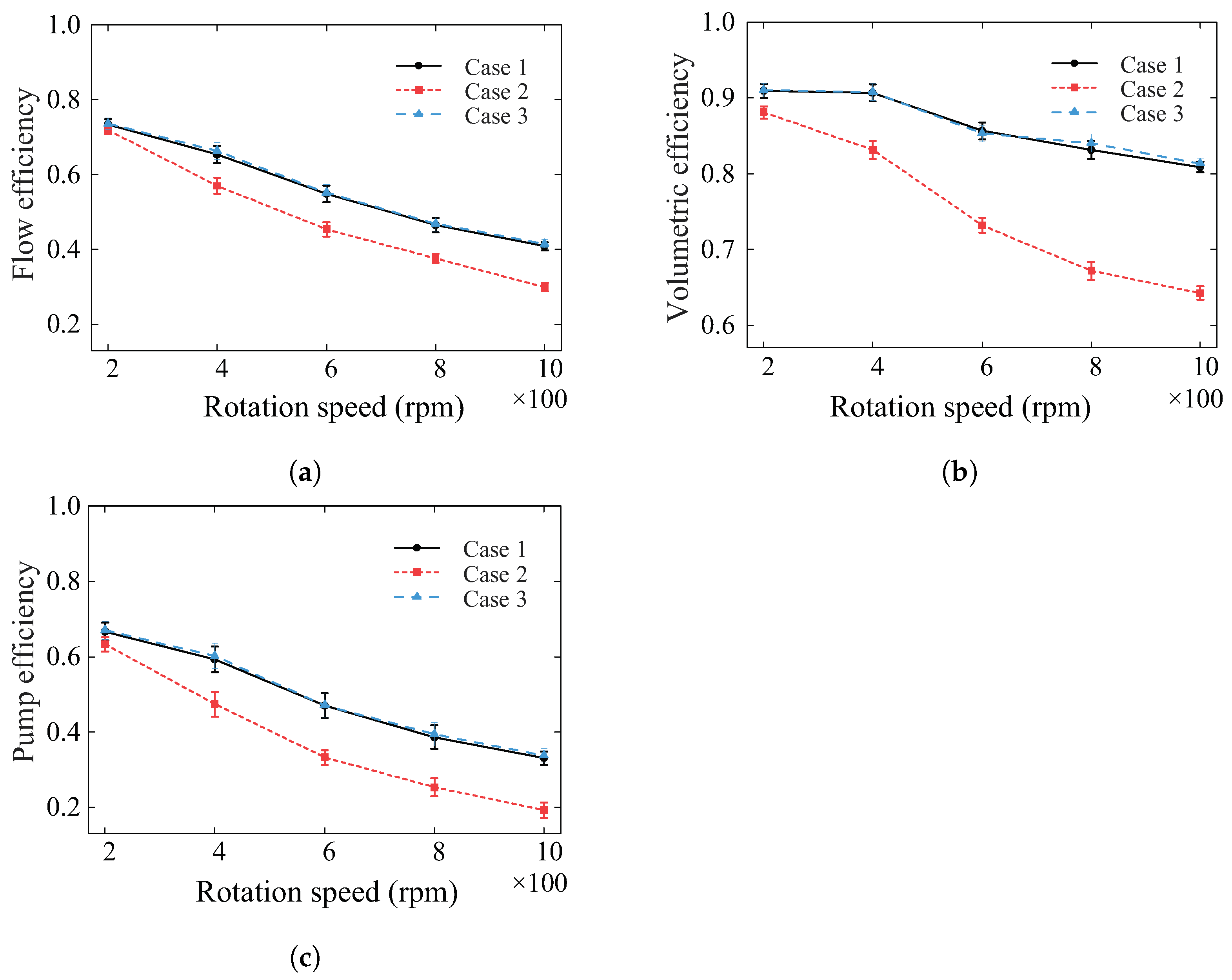
4.2. Effect of Rotational Speeds

To achieve long endurance, the underwater turbine power system usually operates with multiple speed modes. In this semi-closed system, the gas-liquid two-phase Roots pump is driven by the engine. Consequently, the rotational speed of gas-liquid two-phase Roots pump changes accordingly. During the experiment, the rotational speed of the driving motor is gradually increased from 200 rpm to 1000 rpm. This is to highlight the influence of the rotational speed on the efficiency of the Roots pump experimentally. Again, three different valve openings are investigated, and the setup is identical to Section 4.1. The fixed water volumetric flow rate of 200 L/h is employed, as controlled by the driving motor speed. The air volumetric flow rate is significantly influenced by the pump speed as listed in Table 3, where the inlet pressure and outlet pressure are also recorded.
Figure 6 shows the pressure ratio in terms of the rotational speed (from 200 rpm to 1000 rpm with an interval of 200 rpm) for three different valve openings. As the rotational speed increases, the pressure ratio increases from 1.04 (200 rpm) to 1.34 (1000 rpm) for case 2 and from 1.01 (200 rpm) to 1.1 (1000 rpm) for case 3. The smaller valve opening leads to a larger pressure ratio as the rotational speed increases. The effect of the rotational speed on the efficiency of the Roots pump at different valve openings is displayed in Figure 7. The influence of the valve opening on the flow efficiency is consistent, and the increased rotational speed results in decreased flow efficiency. As shown in Figure 7b, a decreased volumetric efficiency in terms of the rotational speed is found for all three operating conditions. At case 2, the volumetric efficiency decreases from 88.07% at 200 rpm to 64.23% at 1000 rpm. In addition, the results from case 1 and case 3 approximately overlap due to the larger opening of the outlet shut-off valve, which leads to a smaller pressure change. The pump efficiency is finally depicted in Figure 7c, showing the same trend in terms of the rotational speed. In summary, as the rotational speed increases, the flow efficiency, volumetric efficiency, and pump efficiency of the Roots pump decrease, and higher pressure ratios are associated with a larger decrease in efficiency (case 2).
During the experiment, the air shut-off valve and the outlet shut-off valve have a fixed opening. With the increase in the rotational speed, the volumetric flow rate of the Roots pump increases accordingly, and the squeezing effect is intensified. Therefore, the pump outlet pressure increases, as shown in Figure 6, and subsequently, the blade moment is also augmented. The high pressure ratio leads to increased leakage flow, resulting in a reduction in the real power. Therefore, the increase in the rotational speed leads to a reduction in the flow efficiency. On the contrary, the volumetric efficiency increases with the rotational speed, as discussed in Ref. [25]. This is due to the fact that the leakage is approximately the same and the theoretical volume flow rate increases at the small gap in Ref. [25]. However, in this experiment, the gap between the rotor and the casing is approximately 0.6 mm, resulting the higher leakage when the rotational speed increases. Consequently, the pump efficiency of the Roots pump is reduced with the increased rotational speed.

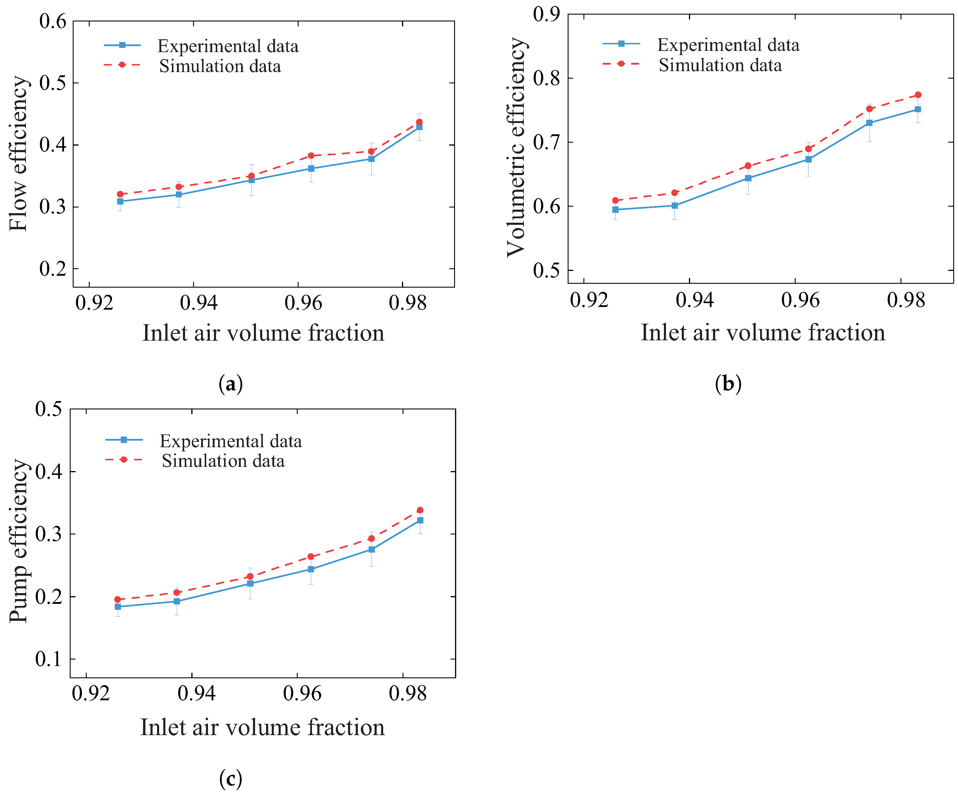
4.3. Numerical Validation

To simulate the liquid–gas two phase flow within Roots pumps, the corresponding numerical model is proposed in Refs. [7,25] and the commericial software Fluent 21.0 is utilized. The two-phase flow is modeled with the mixture multiphase model, while the SST k- ω model is utilized for turbulence closure [26]. The fixed total pressure and temperature are defined at the pump inlet, while a static pressure is set at the outlet. More details on the numerical model setup can be found in Refs. [7,25]. For numerical validations, the gap between the rotor and casing is set as 0.6 mm. Since the numerical model is not thoroughly validated in Refs. [7,25], this section again aims to validate the numerical model against the experimental results of the two-phase Roots pump. This is to highlight the suitability of the numerical model.
The validation case with the rotational speed of 600 rpm is utilized, and the working fluid is water and air. Case 1 in Section 4.1 with different inlet gas volume fractions is employed as the validation case. The total pressure is employed as the boundary conditions, as listed in Table 2, while the inlet temperature is set to 300 K. The inlet volume flow rate is first compared between numerical and experimental results, as shown in Table 4. The numerical volume flow rate is slightly larger than the experimental results, with a maximum difference of 3.64%, which is acceptable.
To provide more information, the efficiency of the Roots pump at different inlet air volume fractions is compared in Figure 8. The efficiency from the numerical simulation is slightly higher than that of the experimental results, and the maximum difference among the volumetric, flow, and pump efficiency is approximately 7.53%. The difference can be attributed to the inaccurate prediction of the gap measurement within the Roots pump. However, the overall difference is acceptable, indicating that the numerical model can be used for the two-phase Roots pump’s performance prediction. The limitation of the current numerical model is that the mixture model can accurately model the separated flow with the clear gas-liquid interface. However, the mixture model fails to predict the bubbly flow within the Roots pumps. The use of hybrid VOF/Euler method is recommended for the future.

5. Conclusions

In this paper, a Roots pump’s performance operating with a gas-liquid two-phase mixture is experimentally investigated. The pump performance in terms of inlet gas volume fractions and rotational speed is discussed. In addition, the numerical method is also thoroughly validated against the experimental results. The key findings are as follows.
  • The Roots pump’s performance is significantly influenced by the inlet air volume fraction. In experimental conditions, the pump efficiency increased from 18.35% to 32.22% with the increasing air volume fraction in case 1. The leakage was affected by the inlet air volume fraction and the pressure difference. The water was able to reduce the rise in compression temperature. The high water volume fraction or low inlet air volume fraction leads to decreased pump efficiency.
  • As the pressure ratio increases, the volumetric efficiency, flow efficiency, and pump efficiency of the Roots pump decrease. The pressure ratio has the potential to be further increased, but a progressively higher pressure ratio enhances the back-flow, leading to a decrease in the pump efficiency.
  • The efficiency of the numerical and experimental methods was compared, and the maximum difference was 7.53%, indicating that the numerical model for the prediction of the performance of the gas-liquid two-phase Roots pump is acceptable. This can be used for following studies on the characteristics of the internal flow field of a gas-liquid two-phase Roots pump.

Author Contributions

Conceptualization, K.Q. and K.L.; methodology, K.Q. and Q.G.; software, Y.Z. and Q.G.; validation, Y.Z., T.Y. and Q.G.; investigation, K.L. and K.Q.; data curation, K.Q., Y.Z. and T.Y.; writing—original draft preparation, K.Q. and Y.Z.; writing—review and editing, K.L., Q.G. and T.Y.; funding acquisition, K.Q. and K.L. All authors have read and agreed to the published version of the manuscript.

Funding

This research was supported by the National Natural Science Foundation of China (NSFC) (Grant No. 52476035) and Innovation Capability Support Program of Shaanxi (Program No. 2024RS-CXTD-15).

Data Availability Statement

The data are not publicly available due to project administration policy.

Conflicts of Interest

The authors declare no conflicts of interest.

References

  1. Wang, X.; Shang, J.; Luo, Z.; Tang, L.; Zhang, X.; Li, J. Reviews of power systems and environmental energy conversion for unmanned underwater vehicles. Renew. Sustain. Energy Rev. 2012, 16, 1958–1970. [Google Scholar] [CrossRef]
  2. Kiely, D.H.; Moore, J.T. Hydrocarbon fueled UUV power systems. In Proceedings of the 2002 Workshop on Autonomous Underwater Vehicles, 2002, San Antonio, TX, USA, 21 June 2002. [Google Scholar]
  3. Qin, K.; Zhang, A.; Guo, Q.; Zhang, J.; Luo, K. Influence of operating conditions on in-tube vapour condensation heat transfer characteristics in the presence of noncondensable gases at high pressure. Appl. Therm. Eng. 2023, 226, 120243. [Google Scholar] [CrossRef]
  4. Yue, X.; Zhang, Y.; Su, Z.; Ba, D.; Wang, G.; Zhang, Z. CFD-based analysis of gas flow in dry scroll vacuum pump. Vacuum 2017, 139, 127–135. [Google Scholar] [CrossRef]
  5. Guo, G.; Zhang, R.; Jiang, L.; Yang, J. Study on mechanism of unsteady gas-liquid two-phase flow in liquid-ring vacuum pump. Vacuum 2024, 222, 113077. [Google Scholar] [CrossRef]
  6. Mansour, M.; Parikh, T.; Engel, S.; Thévenin, D. Numerical Investigations of Gas-Liquid Two-Phase Flow in a Pump Inducer. J. Fluids Eng. 2019, 142, 021302. [Google Scholar] [CrossRef]
  7. Guo, Q.; Qin, K.; Li, D.; Huang, C.; Luo, K. Numerical investigation and performance enhancement of roots pumps operating with gas-liquid mixtures. Vacuum 2020, 176, 109303. [Google Scholar] [CrossRef]
  8. Shao, C.; Li, C.; Zhou, J. Experimental investigation of flow patterns and external performance of a centrifugal pump that transports gas-liquid two-phase mixtures. Int. J. Heat Fluid Flow 2018, 71, 460–469. [Google Scholar] [CrossRef]
  9. Zhang, J.; Cai, S.; Li, Y.; Zhu, H.; Zhang, Y. Visualization study of gas-liquid two-phase flow patterns inside a three-stage rotodynamic multiphase pump. Exp. Therm. Fluid Sci. 2016, 70, 125–138. [Google Scholar] [CrossRef]
  10. Zhang, F.; Bohle, M.; Yuan, S. Experimental investigation on the performance of a side channel pump under gas-liquid two-phase flow operating condition. Proc. Inst. Mech. Eng. Part A J. Power Energy 2017, 231, 645–653. [Google Scholar] [CrossRef]
  11. Luo, X.; Yan, S.; Sun, S.; Feng, J.; Xie, H.; Zhang, L.; He, D. Experimental study of gas-liquid two-phase operating characteristics and bubble evolution law of a semi-open mixed-flow pump. Ocean. Eng. 2023, 272, 113733. [Google Scholar] [CrossRef]
  12. Yang, X.; Hu, C.; Hu, Y.; Qu, Z. Theoretical and Experimental Study of a Synchronal Rotary Multiphase Pump at Very High Inlet Gas Volume Fractions. Appl. Therm. Eng. 2017, 110, 710–719. [Google Scholar] [CrossRef]
  13. Ge, Z.G.; Feng, J.J.; Luo, X.Q.; Zhu, G.J.; He, D.H. Numerical investigation of gas-liquid two-phase performance in a mixed-flow pump by using a modified drag force model. Phys. Fluids 2023, 35, 053324. [Google Scholar]
  14. Wang, J.; Zha, H.; McDonough, J.; Zhang, D. Analysis and numerical simulation of a novel gas-liquid multiphase scroll pump. Int. J. Heat Mass Transf. 2015, 91, 27–36. [Google Scholar] [CrossRef]
  15. Luo, X.; Xie, H.; Feng, J.; Ge, Z.; Zhu, G. Influence of the balance hole on the performance of a gas-liquid two–phase centrifugal pump. Ocean. Eng. 2022, 244, 110316. [Google Scholar] [CrossRef]
  16. Hong, S.; Son, G. Numerical study of a vane vacuum pump with two-phase flows. J. Mech. Sci. Technol. 2017, 31, 3329–3335. [Google Scholar] [CrossRef]
  17. Lobsinger, T.; Hieronymus, T.; Brenner, G. A CFD Investigation of a 2D Balanced Vane Pump Focusing on Leakage Flows and Multiphase Flow Characteristics. Energies 2020, 13, 3314. [Google Scholar] [CrossRef]
  18. Zhang, W.; Yu, Z.; Zahid, M.N.; Li, Y. Study of the Gas Distribution in a Multiphase Rotodynamic Pump Based on Interphase Force Analysis. Energies 2018, 11, 1069. [Google Scholar] [CrossRef]
  19. Feng, J.; Xing, L.; Wang, B.; Wei, H.; Xing, Z. Effects of Working Fluids on the Performance of a Roots Pump for Hydrogen Recirculation in a PEM Fuel Cell System. Appl. Sci. 2020, 10, 8069. [Google Scholar] [CrossRef]
  20. Zhang, R.; Guo, G. Experimental study on gas-liquid transient flow in liquid-ring vacuum pump and its hydraulic excitation. Vacuum 2020, 171, 109025. [Google Scholar] [CrossRef]
  21. Li, G.; Ding, X.; Wu, Y.; Wang, S.; Li, D.; Yu, W.; Wang, X.; Zhu, Y.; Guo, Y. Liquid-vapor two-phase flow in centrifugal pump: Cavitation, mass transfer, and impeller structure optimization. Vacuum 2022, 201, 111102. [Google Scholar] [CrossRef]
  22. Hsieh, C.F.; Zhou, Q.J. Fluid analysis of cylindrical and screw type Roots vacuum pumps. Vacuum 2015, 121, 274–282. [Google Scholar] [CrossRef]
  23. Sun, S.K.; Zhao, B.; Jia, X.H.; Peng, X.Y. Three-dimensional numerical simulation and experimental validation of flows in working chambers and inlet/outlet pockets of Roots pump. Vacuum 2017, 137, 195–204. [Google Scholar] [CrossRef]
  24. Kong, X.; Han, J.; Guo, Y.; Feng, J.; Peng, X. Investigation on the pressure fluctuation of hydrogen Roots pump with a novel reflow structure for fuel cell vehicles. Int. J. Hydrogen Energy 2024, 50, 66–78. [Google Scholar] [CrossRef]
  25. Guo, Q.; Luo, K.; Li, D.; Huang, C.; Qin, K. Effect of Operating Conditions on the Performance of gas-liquid Mixture Roots Pumps. Energies 2021, 14, 5361. [Google Scholar] [CrossRef]
  26. Menter, F.R. Two-equation eddy-viscosity turbulence models for engineering applications. AIAA J. 1994, 32, 1598–1605. [Google Scholar] [CrossRef]
Figure 1. Schematic diagram of an underwater turbine power system with an extra booster.
Processes 12 01918 g001
Figure 2. Schematic diagram of the investigated two-blade Roots pump; detailed parameters are listed in Table 1.
Processes 12 01918 g002
Figure 3. Schematic diagram and photo of the experimental facility. (a) Schematic diagram; (b) Experimental facility.
Processes 12 01918 g003
Figure 4. Effect of inlet gas volume fractions on the efficiency of Roots pump at different valve openings. (a) Flow efficiency; (b) Volumetric efficiency; (c) Pump efficiency.
Processes 12 01918 g004
Figure 5. Pressure ratio in terms of inlet air volume fraction at different valve openings.
Processes 12 01918 g005
Figure 6. Pressure ratio with the rotational speed at different valve openings.
Processes 12 01918 g006
Figure 7. Effect of rotational speed on the efficiency of the Roots pump under different valve openings. (a) Flow efficiency; (b) Volumetric efficiency; (c) Pump efficiency.
Processes 12 01918 g007
Figure 8. Comparison of the efficiency at different inlet air volume fractions between numerical and experimental results. (a) Flow efficiency; (b) Volumetric efficiency; (c) Pump efficiency.
Processes 12 01918 g008
Table 1. Roots pump’s structural parameters.
Parameters                        Values
Blade outer radius, R m                         37.5 mm
Blade valley radius, b                        25 mm
Width of blade protrusion, d                        37.36 mm
Blade center distance, a                        50 mm
Blade thickness, L                        87.3 mm
Casing diameter, d 1                         75 mm
Casing center distance, b 1                         64.8 mm
Casing thickness, L 1                         87.4 mm
Blade number, z                        2
Table 2. Experimental conditions at different inlet gas volume fraction.
Case 1
Inlet GasLiquid VolumetricAir VolumetricInlet PressureOutlet Pressure
Volume FractionFlow Rate, L/hFlow Rate, g/sPaPa
0.92603502.38699,197147,823
0.93723002.41499,202141,213
0.95112502.45099,081133,589
0.96262002.48099,006129,916
0.97411502.51098,973121,451
0.98331002.58298,833115,291
Case 2
0.91823502.32999,423215,638
0.92323002.37899,350200,235
0.93322502.40499,289176,632
0.95032002.44799,169162,426
0.96821502.49499,151147,884
0.98071002.52599,117135,120
Case 3
0.92713502.39799,163147,541
0.93843002.41899,135141,121
0.95262502.45499,034133,526
0.96212002.47999,012129,938
0.97371502.50898,992121,501
0.98471002.59398,786115,247
Table 3. Experimental conditions at different rotational speeds.
Case 1
Rotational SpeedAir Volumetric Flow Rate, m3/hInlet Pressure PaOutlet Pressure Pa
2002.499,304100,990
4004.899,094102,400
6006.898,692104,429
8008.898,255106,922
100010.797,774109,594
Case 2
2002.399,241103,249
4003.899,016108,595
6006.298,813114,955
8007.098,573122,617
10008.598,409131,868
Case 3
2002.599,002100,840
4004.998,961102,024
6006.998,570103,820
8008.898,107105,816
100010.997,956108,640
Table 4. Inlet working fluid volume flow rate under different inlet air volume fractions.
Inlet Air Volume FractionNumerical Volume Flow Rate, m3/hExperimental Volume Flow Rate, m3/hDeviation
0.92604.884.723.28%
0.93724.954.773.64%
0.95115.265.112.85%
0.96265.545.353.43%
0.97416.015.803.49%
0.98336.185.973.40%
Disclaimer/Publisher’s Note: The statements, opinions and data contained in all publications are solely those of the individual author(s) and contributor(s) and not of MDPI and/or the editor(s). MDPI and/or the editor(s) disclaim responsibility for any injury to people or property resulting from any ideas, methods, instructions or products referred to in the content.

