Thermodynamic Feasibility of Chemical Looping CO Production from Blast Furnace Gas Based on Fe-Ca-Based Carriers


Abstract
1. Introduction
2. Methodology
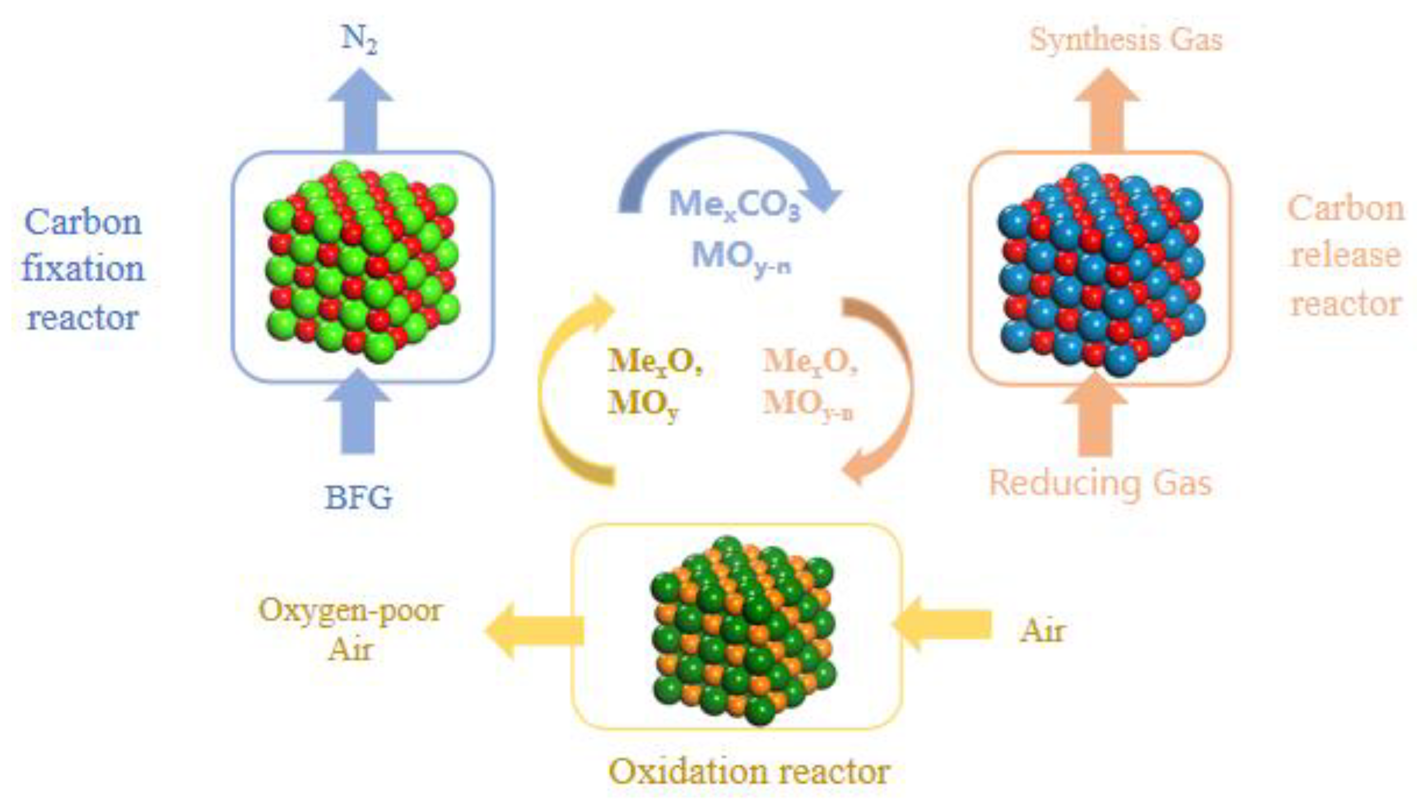
2.1. Process Model Description

| Reaction Equation | /kJ·mol−1 | Numbering |
|---|---|---|
| The main chemical reactions in the carbon fixation reactor | ||
| FeO + CO(g) = Fe + CO2(g) | −15.262 | (2) |
| 3FeO + CO2(g) = Fe3O4 + CO(g) | −30.410 | (3) |
| 2FeO + CO2(g) = Fe2O3 + CO(g) | −5.341 | (4) |
| 4FeO = Fe + Fe3O4 | −45.671 | (5) |
| CaO + CO2(g) = CaCO3 | −178.255 | (6) |
| The main chemical reactions in the carbon release reactor | ||
| CaCO3 = CaO + CO2(g) | +178.255 | (7) |
| CO2(g) + Fe = CO(g) + FeO | +15.262 | (8) |
| 3CO2(g) + CH4(g) = 4CO(g) + 2H2O(g) | +328.476 | (9) |
| CO2(g) + CH4(g) = 2CO(g) + 2H2(g) | +245.931 | (10) |
| CH4(g) = 2H2(g) + C | +73.843 | (11) |
| C + CO2(g) = 2CO(g) | +172.084 | (12) |
| 3FeO + CH4(g) = 3Fe + CO(g) + 2H2O(g) | +282.687 | (13) |
| 3Fe3O4 + CH4(g) = 9FeO + CO(g) + 2H2O(g) | +419.703 | (14) |
2.2. Process Evaluation
3. Results and Discussion
3.1. Product Characteristic of Carbon Fixation Step
3.1.1. Effect of CaO/C
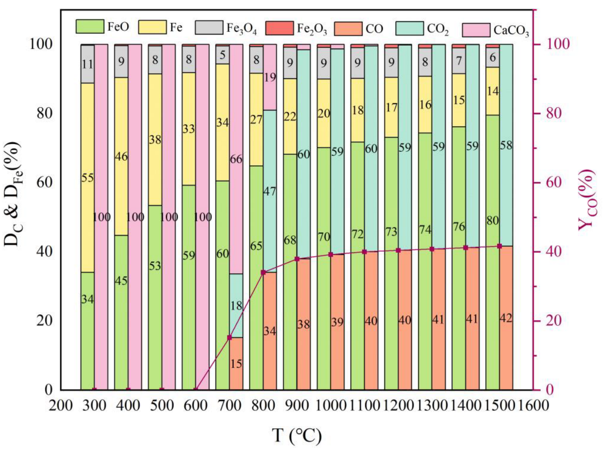
3.1.2. Effect of Temperature
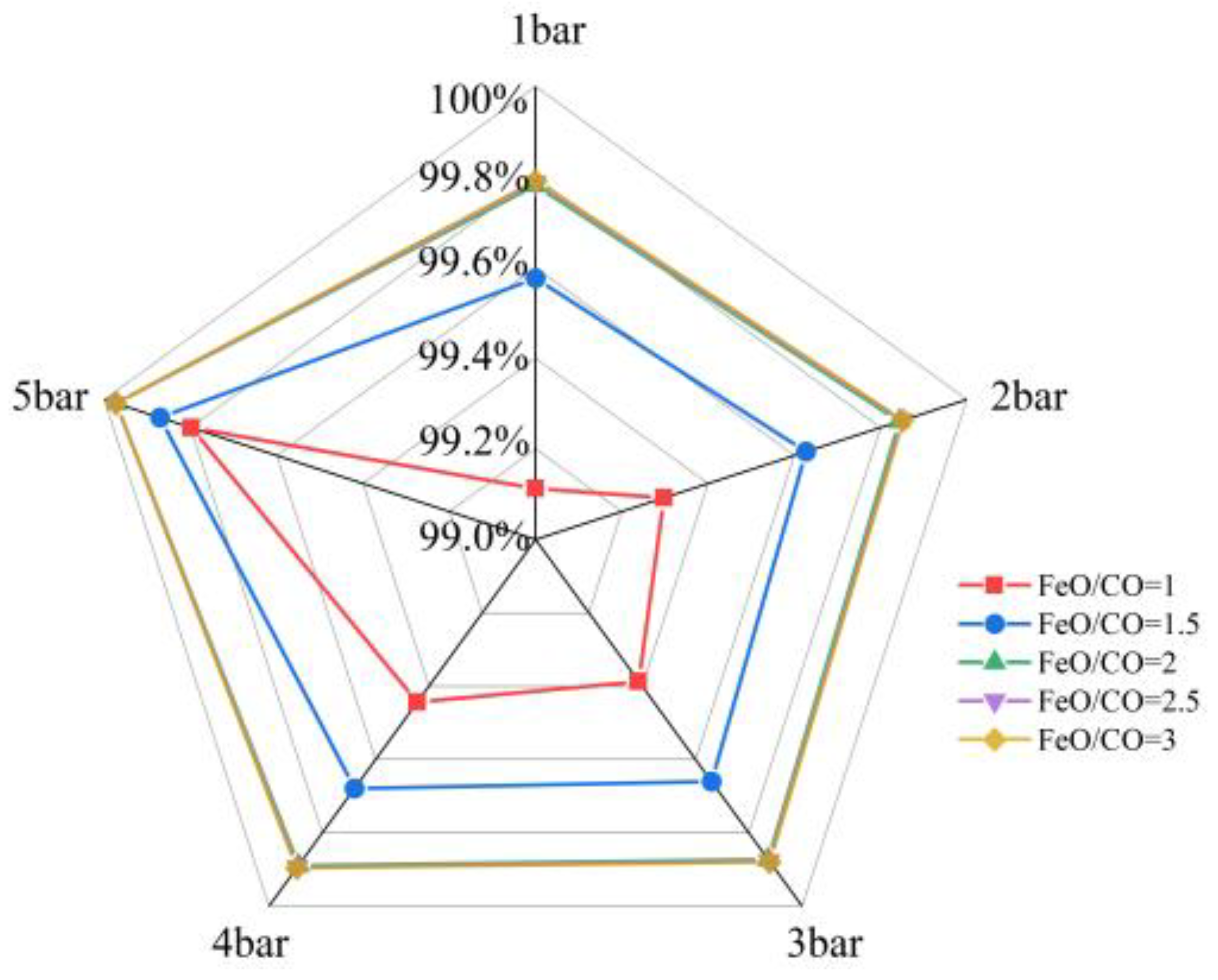
3.1.3. Effect of FeO/CO and Pressure
3.2. Product Characteristic of Carbon Release Step
3.2.1. With Absence of Reducing Gas
Effect of Temperature
Effect of Pressure
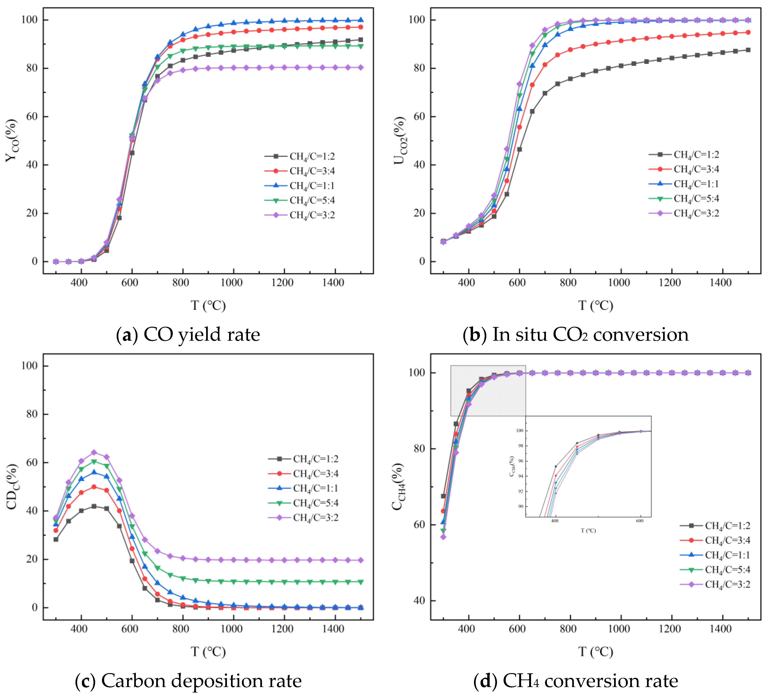
3.2.2. With Presence of Reducing Gas
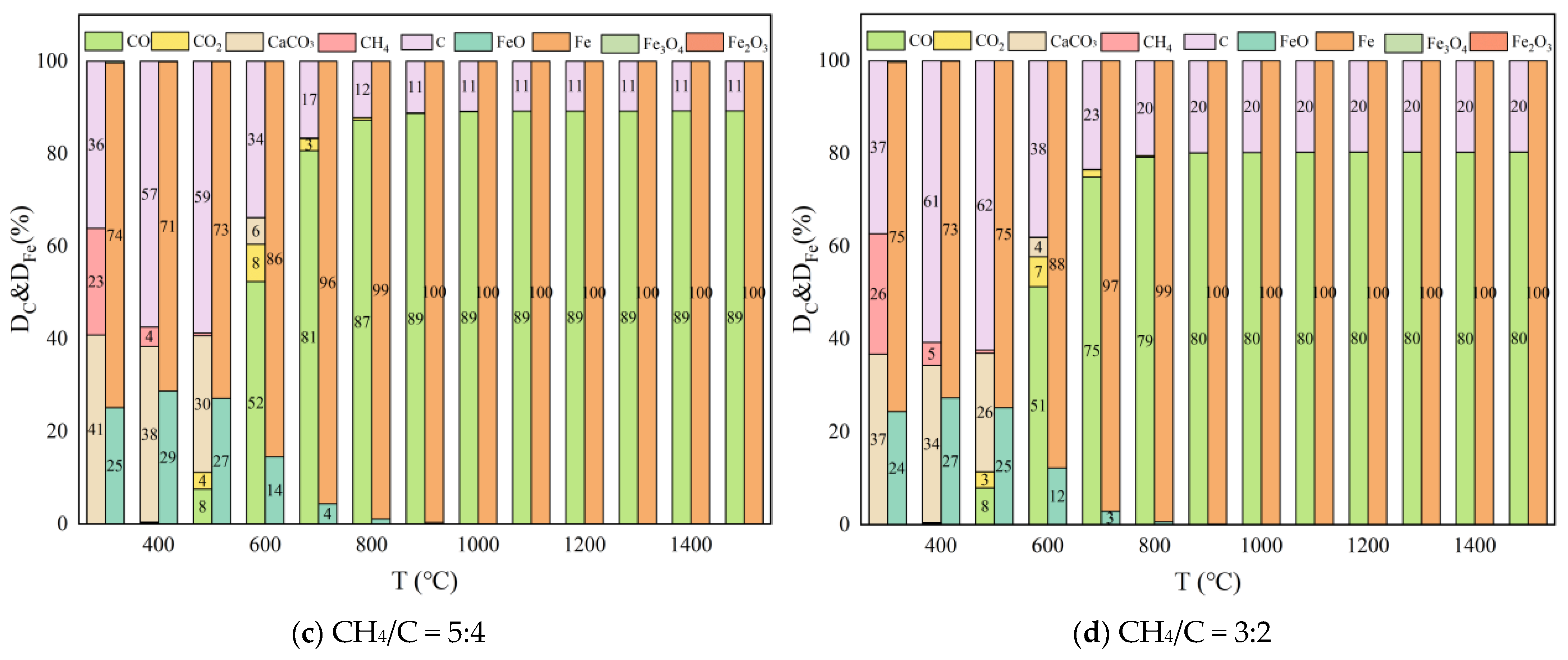
Effect of Temperature
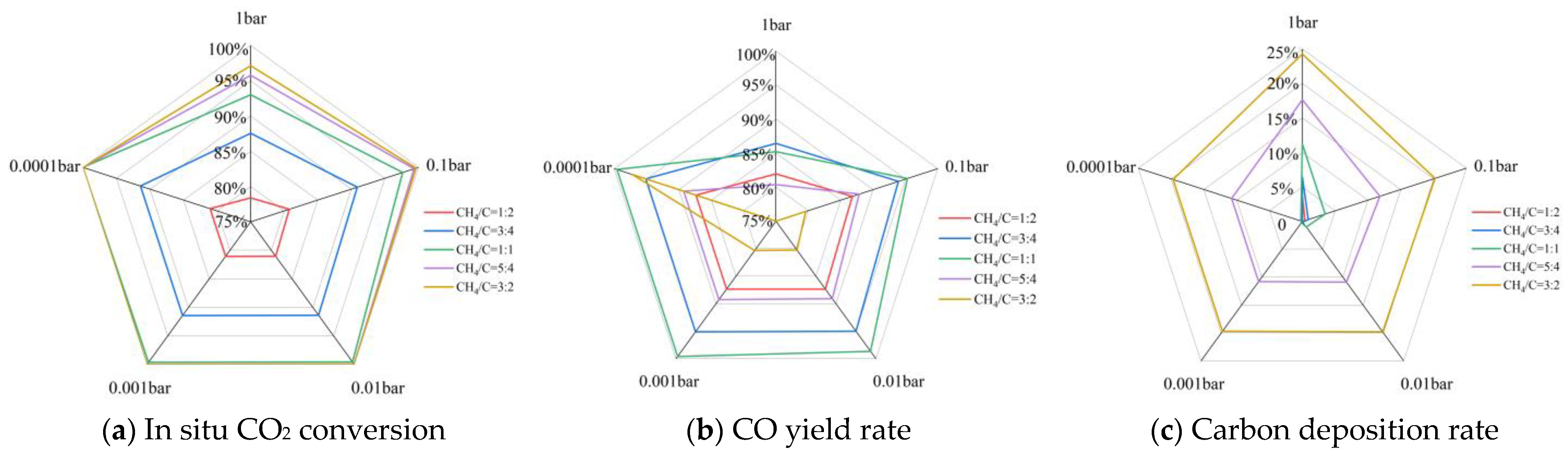
Effect of CH4/C and Pressure
3.3. System Energy Consumption
4. Conclusions
Author Contributions
Funding
Data Availability Statement
Conflicts of Interest
Abbreviations
| BFG | Blast Furnace Gas | CCU | Carbon capture and utilization |
| ICCU | Integration of carbon dioxide capture and utilization | DC | C distribution |
| DFe | Fe distribution | YCO | CO yield rate |
| UCO2 | in situ CO2 utilization rate | CCH4 | CH4 conversion rate |
| FC | carbon fixation rate |
References
- Caillat, S. Burners in the steel industry: Utilization of by-product combustion gases in reheating furnaces and annealing lines. Energy Procedia 2017, 120, 20–27. [Google Scholar] [CrossRef]
- James, J.; Lücking, L.E.; van Dijk, H.A.J.; Boon, J. Review of technologies for carbon monoxide recovery from nitrogen-containing industrial streams. Front. Chem. Eng. 2023, 5, 1066091. [Google Scholar] [CrossRef]
- Voss, C. CO2 removal by PSA: An industrial view on opportunities and challenges. Adsorption 2014, 20, 295–299. [Google Scholar] [CrossRef]
- Fang, M.; Yi, N.; Di, W.; Wang, T.; Wang, Q. Emission and control of flue gas pollutants in CO2 chemical absorption system—A review. Int. J. Greenh. Gas Control 2020, 93, 102904. [Google Scholar] [CrossRef]
- Duan, H.; Wang, S.; Yang, X.; Yuan, X.; Zhang, Q.; Huang, Z.; Guo, H. Simultaneous separation of copper from nickel in ammoniacal solutions using supported liquid membrane containing synergistic mixture of M5640 TRPO. Chem. Eng. Res. Des. 2017, 117, 460–471. [Google Scholar] [CrossRef]
- Cherif, A.; Atwair, M.; Atsbha, T.A.; Zarei, M.; Duncan, I.J.; Nebbali, R.; Sen, F.; Lee, C.J. Enabling low-carbon membrane steam methane reforming: Comparative analysis and multi-objective NSGA-II-integrated Bayesian optimization. Energy Convers. Manag. 2023, 297, 117718. [Google Scholar] [CrossRef]
- D’Aquila, A.; Jechura, J.L.; Wolden, C.A. Techno-economic analysis of zero-carbon ammonia-hydrogen fuel blend production through a catalytic membrane reformer and packed bed reactor. Renew. Sustain. Energy Rev. 2024, 199, 114469. [Google Scholar]
- Ben-Mansour, R.; Haque MD, A.; Harale, A.; Paglieri, S.N.; Alrashed, F.S.; Shakeel, M.R.; Mokheimer, E.M.A.; Habib, M.A. Comprehensive parametric investigation of methane reforming and hydrogen separation using a CFD model. Energy Convers. Manag. 2021, 249, 114838. [Google Scholar] [CrossRef]
- Liu, W.; Zuo, H.; Wang, J.; Yang, F. The yield and application of hydrogen in steel industry. Int. J. Hydrogen Energy 2021, 46, 10548–10569. [Google Scholar] [CrossRef]
- Chronopoulos, T.; Fernandez-Diez, Y.; Maroto-Valer, M.M.; Ocone, R.; Reay, D. CO2 desorption via microwave heating for post-combustion carbon capture. Microporous Mesoporous Mater. 2014, 197, 288–290. [Google Scholar] [CrossRef]
- Fernández, J.; Sotenko, M.; Derevschikov, V.; Lysikov, A.; Rebrov, E.R. A radiofrequency heated reactor system for post-combustion carbon capture. Chem. Eng. Process. Process Intensif. 2016, 108, 17–26. [Google Scholar] [CrossRef]
- Yamada, H. Amine-based capture of CO2 for utilization and storage. Polym. J. 2021, 53, 93–102. [Google Scholar] [CrossRef]
- Song, K.S.; Fritz, P.W.; Coskun, A. Porous organic polymers for CO2 capture, separation and conversion. Chem. Soc. Rev. 2022, 51, 9831–9852. [Google Scholar] [CrossRef]
- Zhang, P.; Tong, J.; Huang, K.; Zhu, X.; Yang, W. The current status of high temperature electrochemistry-based CO2 transport membranes and reactors for direct CO2 capture and conversion. Prog. Energy Combust. Sci. 2021, 82, 100888. [Google Scholar] [CrossRef]
- Review of synergistic photo-thermo-catalysis: Mechanisms, materials and applications. Int. J. Hydrogen Energy 2020, 45, 30288–30324. [CrossRef]
- Tang, Y.; Wu, S.; Wang, Y.; Song, L.; Yang, Z.; Guo, C.; Liu, J.; Wang, F. Photo-assisted catalytic CO2 hydrogenation to CO with nearly 100% selectivity over Rh/TiO2 catalysts. Energy Fuels 2022, 37, 539–546. [Google Scholar] [CrossRef]
- He, X.; Liu, M.; Liang, Z.; Wang, Z.; Wang, P.; Liu, Y.; Cheng, H.; Dai, Y.; Zheng, Z.; Huang, B. Photo-enhanced CO2 hydrogenation by plasmonic Cu/ZnO at atmospheric pressure. J. Solid State Chem. 2021, 298, 122113. [Google Scholar] [CrossRef]
- Mikkelsen, M.; Jørgensen, M.; Krebs, F.C. The teraton challenge. A review of fixation and transformation of carbon dioxide. Energy Environ. Sci. 2010, 3, 43–81. [Google Scholar] [CrossRef]
- Pan, Q.; Peng, J.; Sun, T.; Wang, S.; Wang, S. Insight into the reaction route of CO2 methanation: Promotion effect of medium basic sites. Catal. Commun. 2014, 45, 74–78. [Google Scholar] [CrossRef]
- Mun, Y.; Lee, S.; Cho, A.; Kim, S.; Han, J.; Lee, J. Cu-Pd alloy nanoparticles as highly selective catalysts for efficient electrochemical reduction of CO2 to CO. Appl. Catal. B Environ. 2019, 246, 82–88. [Google Scholar] [CrossRef]
- Zeng, L.; Cheng, Z.; Fan, J.A.; Fan, L.S.; Gong, J. Metal oxide redox chemistry for chemical looping processes. Nat. Rev. Chem. 2018, 2, 349–364. [Google Scholar] [CrossRef]
- Singh, V.; Buelens, L.C.; Poelman, H.; Saeys, M.; Marin, G.B.; Galvita, V.V. Carbon monoxide yield using a steel mill gas in a combined chemical looping process. J. Energy Chem. 2022, 68, 811–825. [Google Scholar] [CrossRef]
- Erans, M.; Manovic, V.; Anthony, E.J. Calcium looping sorbents for CO2 capture. Appl. Energy 2016, 180, 722–742. [Google Scholar] [CrossRef]
- Di, Z.; Yilmaz, D.; Biswas, A.; Cheng, F.; Leion, H. Spinel ferrite-contained industrial materials as oxygen carriers in chemical looping combustion. Appl. Energy 2022, 307, 118298. [Google Scholar] [CrossRef]
- Ma, J.; Han, D.; Zhao, H. Investigation on iron ore for the oxygen carrier aided combustion. Fuel Process. Technol. 2022, 230, 107214. [Google Scholar] [CrossRef]
- Wang, K.; Yu, Q.; Qin, Q.; Duan, W. Feasibility of a Co oxygen carrier for chemical looping air separation: Thermodynamics and kinetics. Chem. Eng. Technol. 2014, 37, 1500–1506. [Google Scholar] [CrossRef]
- Wang, K.; Yu, Q.; Wang, Q.; Hua, J.; Peng, R. Oxygen uncoupling property and kinetics of a copper manganese composite oxygen carrier in a packed-bed reactor. Energy Fuels 2020, 34, 6158–6167. [Google Scholar] [CrossRef]
- Liu, Z.; Yu, Q.; Wang, H.; Wu, J.; Tao, S. Selecting nitrogen carriers used for chemical looping ammonia generation of biomass and H2O by thermodynamic method. Int. J. Hydrogen Energy 2023, 48, 4035–4051. [Google Scholar] [CrossRef]
- Hua, J.; Wang, K.; Wang, Q.; Peng, R. Feasibility of Fe-based nitrogen carrier for chemical looping ammonia synthesis: Thermodynamics. J. Therm. Anal. Calorim. 2021, 146, 673–680. [Google Scholar] [CrossRef]
- Wang, S.; Gong, F.; Zhou, Q.; Xie, Y.; Li, H.; Li, M.; Fu, E.; Yang, P.; Jing, Y.; Xiao, R. Transition metal enhanced chromium nitride as composite nitrogen carrier for sustainable chemical looping ammonia synthesis. Appl. Catal. B Environ. 2023, 339, 123134. [Google Scholar] [CrossRef]
- Luo, C.; Dou, B.; Zhang, H.; Zeng, P.; Gao, D.; Wang, Y.; Chen, H.; Xu, Y. Hydrogen and syngas co-yield by coupling of chemical looping water splitting and glycerol oxidation reforming using Ce–Ni modified Fe-based oxygen carriers. J. Clean. Yield 2022, 335, 130299. [Google Scholar]
- Chiron, F.X.; Patience, G.S. Kinetics of mixed copper–iron based oxygen carriers for hydrogen yield by chemical looping water splitting. Int. J. Hydrogen Energy 2012, 37, 10526–10538. [Google Scholar] [CrossRef]
- Xuan, Y.; Gao, H.; Tian, H.; Hu, Z.; Ma, J.; Yu, Q. Enhancement effect of Ce addition on Mn3O4/diatomite sorbent for moderate-temperature flue gas desulfurization. Chem. Eng. J. 2023, 460, 141592. [Google Scholar] [CrossRef]
- Huang, H.; Ma, J.; Zhao, H.; Zheng, C. Behavior of coal-chlorine in chemical looping combustion. Proc. Combust. Inst. 2023, 39, 4437–4446. [Google Scholar] [CrossRef]
- Sun, Z.; Liu, J.; Sun, Z. Synergistic decarbonization and desulfurization of blast furnace gas via a novel magnesium-molybdenum looping process. Fuel 2020, 279, 118418. [Google Scholar] [CrossRef]
- Palone, O.; Hoxha, A.; Gagliardi, G.G.; Gruttola, F.D.; Borello, D. Methanol yield by a Chemical Looping Cycle Using Blast Furnace Gases//Turbo Expo: Power for Land, Sea, and Air. Am. Soc. Mech. Eng. 2022, 85987. [Google Scholar]
- Flores-Granobles, M.; Saeys, M. Dynamic pressure-swing chemical looping process for the recovery of CO from blast furnace gas. Energy Convers. Manag. 2022, 258, 115515. [Google Scholar] [CrossRef]
- Jin, B.; Wei, K.; Ouyang, T.; Fan, Y.; Zhao, H.; Zhang, H.; Liang, Z. Chemical looping CO2 capture and in-situ conversion: Fundamentals, process configurations, bifunctional materials, and reaction mechanisms. Appl. Energy Combust. Sci. 2023, 16, 100218. [Google Scholar] [CrossRef]
- Yu, Z.; Xie, H.; Guo, R.; Yu, Q.B.; Wang, K.; Shao, Z.; Zhang, W. High-quality utilization of raw coke oven gas for hydrogen production based on CO2 adsorption-enhanced reforming. Energy 2024, 305, 132335. [Google Scholar] [CrossRef]
- Xie, H.; Yu, Z.; Gao, Y.; Qin, M.X.; Ji, L.; Yu, Q.B. Sorption-enhanced reforming of raw COG and its adaptability to hydrogen metallurgy: Thermodynamic analysis. Int. J. Hydrogen Energy 2024, 49, 837–848. [Google Scholar] [CrossRef]
- Wang, S.; Farrauto, R.J.; Karp, S.; Jeon, J.H.; Schrunk, E.T. Parametric, cyclic aging and characterization studies for CO2 capture from flue gas and catalytic conversion to synthetic natural gas using a dual functional material (DFM). J. CO2 Util. 2018, 27, 390–397. [Google Scholar] [CrossRef]
- Kim, S.M.; Abdala, P.M.; Broda, M.; Hosseini, D.; Coperet, C.; Muller, C. Integrated CO2 capture and conversion as an efficient process for fuels from greenhouse gases. ACS Catal. 2018, 8, 2815–2823. [Google Scholar] [CrossRef]
- Zhao, Y.; Jin, B.; Luo, X.; Liang, Z. Thermodynamic evaluation and experimental investigation of CaO-assisted Fe-based chemical looping reforming process for syngas yield. Appl. Energy 2021, 288, 116614. [Google Scholar] [CrossRef]
- Zhao, Y.; Jin, B.; Deng, Z.; Huang, Y.; Lou, X.; Liang, Z. Thermodynamic analysis of a new chemical looping process for syngas yield with simultaneous CO2 capture and utilization. Energy Convers. Manag. 2018, 171, 1685–1696. [Google Scholar] [CrossRef]
- Sun, H.; Wang, J.; Zhao, J.; Shen, B.; Shi, J.; Huang, J.; Wu, C. Dual functional catalytic materials of Ni over Ce-modified CaO sorbents for integrated CO2 capture and conversion. Appl. Catal. B Environ. 2019, 244, 63–75. [Google Scholar] [CrossRef]
- Kim, J.; Son, M.; Han, S.S.; Yoon, Y.S.; Oh, H. Computational-cost-efficient surrogate model of vacuum pressure swing adsorption for CO separation process optimization. Sep. Purif. Technol. 2022, 300, 121827. [Google Scholar] [CrossRef]
- Er-Rbib, H.; Bouallou, C.; Werkoff, F. Dry reforming of methane–review of feasibility studies. Chem. Eng. 2012, 29, 163–168. [Google Scholar]


| Component | N2 | CO | CO2 | H2 |
|---|---|---|---|---|
| Content (mol%) | 50 | 23 | 25 | 2 |
| QR | QO | QC | QRe | QTotal |
|---|---|---|---|---|
| −2.35 MJ/kg | 11.06 MJ/kg | −2.06 MJ/kg | 6.45 MJ/kg | 0.2 MJ/kg |
Disclaimer/Publisher’s Note: The statements, opinions and data contained in all publications are solely those of the individual author(s) and contributor(s) and not of MDPI and/or the editor(s). MDPI and/or the editor(s) disclaim responsibility for any injury to people or property resulting from any ideas, methods, instructions or products referred to in the content. |
© 2024 by the authors. Licensee MDPI, Basel, Switzerland. This article is an open access article distributed under the terms and conditions of the Creative Commons Attribution (CC BY) license (https://creativecommons.org/licenses/by/4.0/).
Share and Cite
Gao, Y.; Xie, H.; Sun, C.; Qin, M.; Wang, K.; Shao, Z. Thermodynamic Feasibility of Chemical Looping CO Production from Blast Furnace Gas Based on Fe-Ca-Based Carriers. Processes 2024, 12, 1965. https://doi.org/10.3390/pr12091965
Gao Y, Xie H, Sun C, Qin M, Wang K, Shao Z. Thermodynamic Feasibility of Chemical Looping CO Production from Blast Furnace Gas Based on Fe-Ca-Based Carriers. Processes. 2024; 12(9):1965. https://doi.org/10.3390/pr12091965
Chicago/Turabian StyleGao, Yang, Huaqing Xie, Chao Sun, Mengxin Qin, Kun Wang, and Zhengri Shao. 2024. "Thermodynamic Feasibility of Chemical Looping CO Production from Blast Furnace Gas Based on Fe-Ca-Based Carriers" Processes 12, no. 9: 1965. https://doi.org/10.3390/pr12091965
APA StyleGao, Y., Xie, H., Sun, C., Qin, M., Wang, K., & Shao, Z. (2024). Thermodynamic Feasibility of Chemical Looping CO Production from Blast Furnace Gas Based on Fe-Ca-Based Carriers. Processes, 12(9), 1965. https://doi.org/10.3390/pr12091965