Article

Control Study on Surrounding Rock of Gob-Side Entry Retaining below near Distance Goaf

1
School of Energy and Mining Engineering, China University of Mining and Technology-Beijing, Beijing 100083, China
2
Beijing Key Laboratory for Precise Mining of Intergrown Energy and Resources, China University of Mining and Technology-Beijing, Beijing 100083, China
3
Shanxi Coking Coal Fenxi Mining Group Co., Ltd., Jiexiu 032006, China
*
Author to whom correspondence should be addressed.
Processes 2024, 12(9), 1966; https://doi.org/10.3390/pr12091966
Submission received: 21 August 2024 / Revised: 8 September 2024 / Accepted: 10 September 2024 / Published: 12 September 2024

Abstract

:
To explore the control technology on surrounding rock of gob-side entry retaining (GSER) below a goaf in a near distance coal seam (NDCS), research was conducted on the floor ruin range, the floor stress distribution features, the layout of the GSER below near distance goaf, the width of the roadside filling wall (RFW), and the control technology of the GSER surrounding rock below the near distance goaf after upper coal seam (UCS) mining. The results show that (1) the stress of the goaf floor has obvious regional features, being divided into stress high value zone (Zone A), stress extremely low zone (Zone B), stress rebound zone (Zone C), stress transition zone (Zone D), and stress recovery zone (Zone E) according to different stress states. The stress distribution features at different depths below the goaf floor in each zone also have differences. (2) Arranging the roadway in Zone A below a coal pillar, the roadway is at high stress levels, which is not conducive to the stability of the surrounding rock. Arranging the roadway in Zone B below the goaf floor, the bearing capacity of the surrounding rock itself is weak, making it difficult to control the surrounding rock. Arranging the roadway in Zone C, the mechanical properties of the surrounding rock are good, and the difficulty of controlling the surrounding rock is relatively low. Arranging the roadway in Zone D and Zone E, there is a relatively small degree of stress concentration in the roadway rib. (3) When the RFW width is 0.5–1.5 m, stress concentration is more pronounced on the solid coal rib, and the overlying rock pressure is mainly borne by the solid coal rib, with less stress on the RFW. When the RFW width is 2~3 m, the stress on the RFW is enhanced, and the bearing capacity is significantly increased compared to RFW of 0.5–1.5 m width. The RFW contributes to supporting the overlying rock layers. (4) A comprehensive control technology for GSER surrounding rock in lower coal seam (LCS) has been proposed, which includes the grouting modification of coal and rock mass on the GSER roof, establishing a composite anchoring structure formed by utilizing bolts (cables); the strong support roof and control floor by one beam + three columns, reinforcing the RFW utilizing tie rods pre-tightening; and the hydraulic prop protection RFW and bolts (cables) protection roof at roadside. This technology has been successfully applied in field practice.

1. Introduction

Coal is an important energy resource in China and plays a significant role in the country’s energy structure. However, with the increase in coal resource mining intensity, coal reserves with superior mining conditions are approaching depletion, causing coal seams with poor mining conditions to gradually become mainstream mining coal seams. Among them, an NDCS with small interlayer spacing are difficult to mine due to their poor occurrence conditions [1,2,3]. At the same time, the high excavation rate of mine roadways, tight mining succession, and stress concentration of coal pillars in multi-seam mining have limited the efficient and safe production of mines [4,5,6,7]. So, coal resources with superior storage conditions are becoming increasingly scarce, leading enterprises to pay attention to the resource development of near distance coal seam groups. Also, in order to reduce resource loss and avoid stress concentration in coal pillars, the technique of GSER formed by RFW is widely used in coal seam mining [8,9,10]. The excavation of underground engineering leads to the continuous evolution of the fracture characteristics of the coal and rock masses [11,12,13], especially during NDCS mining, where the cracks in the surrounding rock of the roadway continue to develop and expand, posing great difficulties for controlling the roadway surrounding rock during NDCS mining. Over the years, numerous scholars and on-site engineering technicians have conducted extensive research on the mining of the NDCS.
In an inclined NDCS, the literature analyzed the controlling difficulties of the mining roadways’ stability and proposed a corresponding control technique [14]. After the UCS is mined, the literature studied the goaf floor stress distribution, the roadway layout and its control in the LCS [15]. Based on mechanical model of the stress distribution below the coal pillar, the literature deduced tangential, horizontal, and vertical stress equations at any location on the floor below the coal pillar [16]. The literature studied the deviatoric stress features of the mining roadway in the LCS and proposed the control techniques for prop–cable–shed [17]. The literature investigated the control effect of a high-strength prestressed bolt–cable on a LCS large section roadway [18]. The literature proposed a comprehensive control scheme including grouting, long bolt, anchor cable, and U-shaped steel to control the surrounding rock failure of the repeated mining roadway in a NDCS [19]. The literature proposed the method of removing the coal pillar by roof cutting to eliminate the stress concentration of UCS coal pillars, achieving the purpose of protecting the lower roadway [20]. The literature explored the failure features for a roadway under a remaining coal pillar and an irregular goaf in a deep NDCS and proposed an action plan for roadway support [21]. In the end mining stage of the NDCS, the literature discussed the deformation features of the retracement channel of LCS under the superposition of different stresses [22]. The literature proposed a technology of pressure relief of coal pillars in the NDCS and designed a monitoring scheme [23]. The literature investigated the failure process of roadway and chain pillar in the LCS under the effect of the remaining coal pillars [24]. The literature revealed the evolution laws of roof displacement stress and roof caving features in the mining process of the NDCS [25].
In summary, experts and scholars have conducted numerous studies on the technology of the mining of the NDCS and made gratifying progress. However, there is relatively little research on the design and maintenance of the GSER below near distance goaf. Based on the above research, this paper focuses on the controlling difficulties of the GSER surrounding rock below near distance goaf, the floor ruin depth after the UCS mining, the layout of the GSER below near distance goaf, the width of the RFW, and the control mechanisms of the GSER surrounding rock below near distance goaf. The key method to improve the stability of the GSER surrounding rock is to fill the roadside wall at goaf side while using artificial supports (such as bolt and cable support in roadway, and single hydraulic support in the roadway), which can make the GSER surrounding rock support system both highly resistant and compressible. So, a comprehensive control technology for the GSER below near distance goaf has been proposed in this paper, which includes the grouting modification of coal and rock mass on the GSER roof, establishing a composite anchoring structure formed utilizing bolts (cables); the strong support roof and control floor by one beam + three columns, reinforcing the RFW utilizing tie rods pre-tightening; and the hydraulic prop protection RFW and bolts (cables) protection roof at roadside. Afterwards, the project underwent on-site industrial testing and achieved success.

2. Analysis of Engineering Geological Conditions

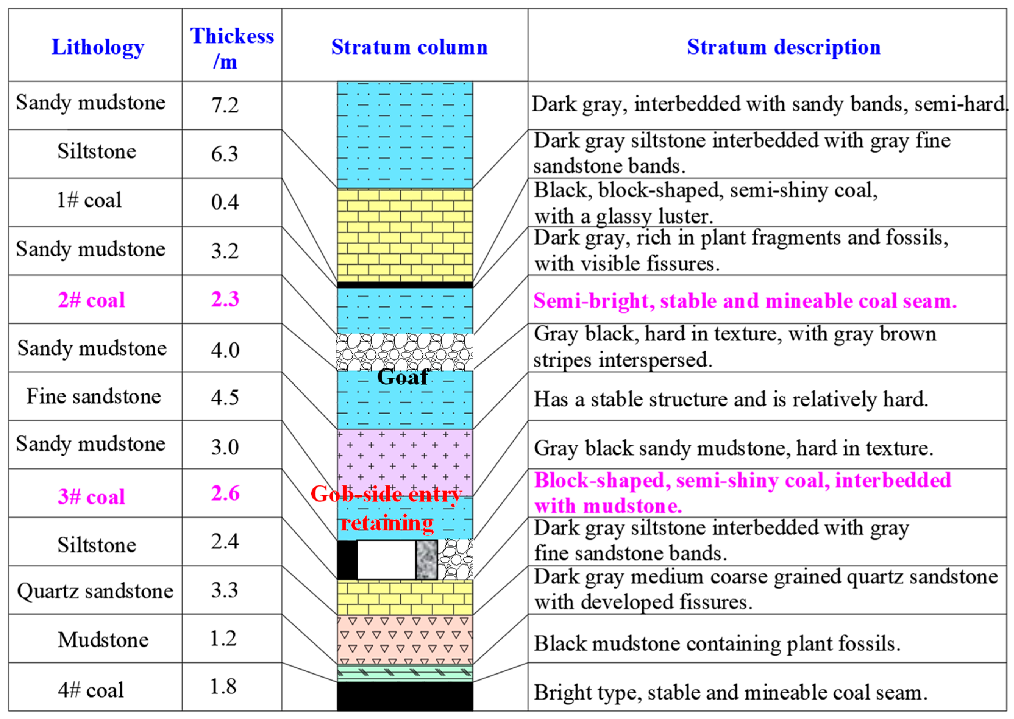
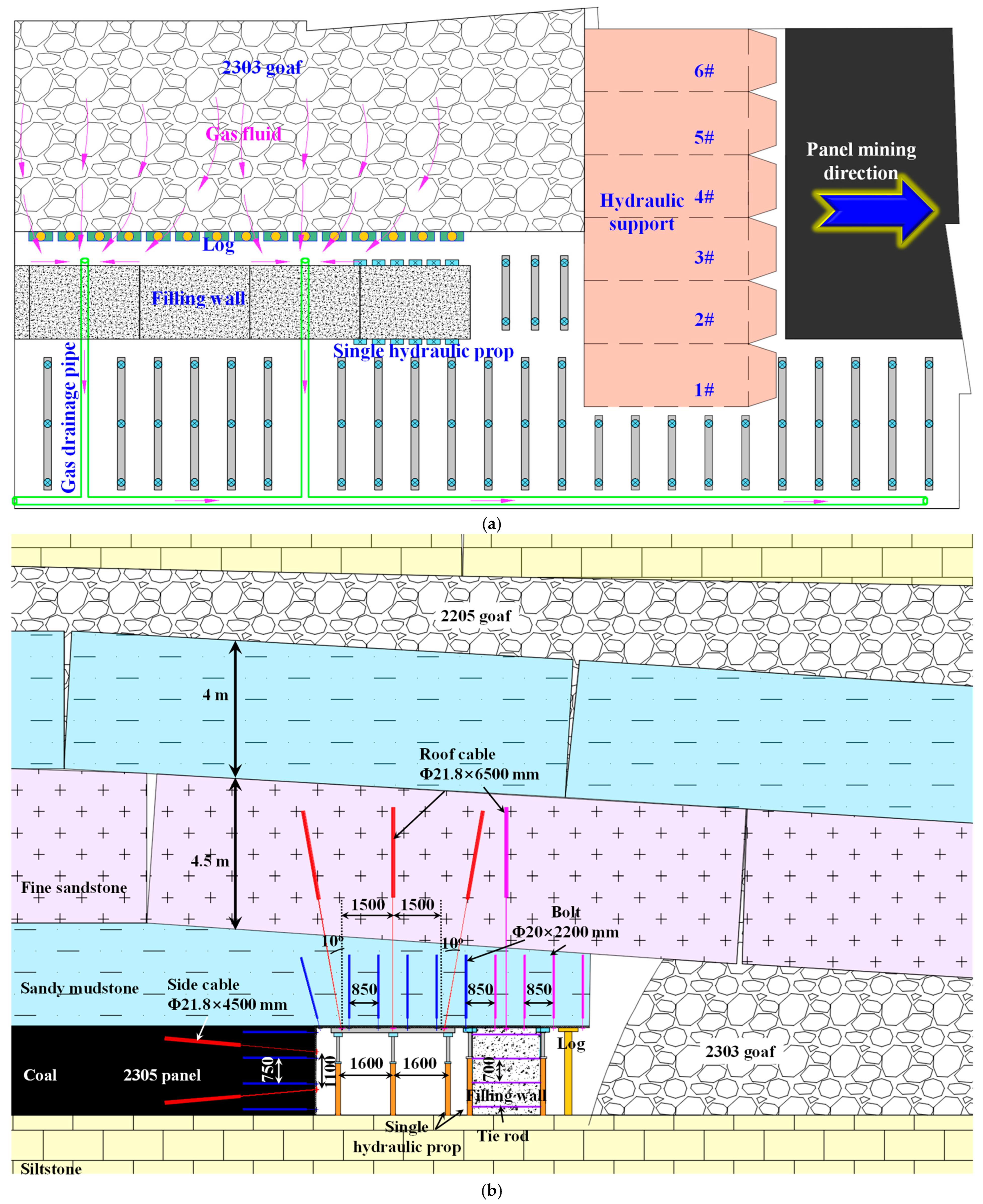
2.1. Production and Geological Conditions of Roadways and Panels

The burial depth of the 2303 panel is about 620 m, and the surrounding 3# coal seams are all unmined areas. The distance between the 3# coal seam roof and the goaf floor of the 2# coal seam is about 11.5 m. There are coal pillars with 20 m width left in the 2# coal seam. The NDCS mining process is as follows: mining of the 2203 panel of the upper 2# coal seam → mining of the 2205 panel of the upper 2# coal seam → excavation of the air-return roadway of the 2303 panel of the lower 3# coal seam → mining of the 2303 panel of the lower 3# coal seam → construction of roadside filling wall → mining of the 2305 panel of the lower 3# coal seam. The production layout of the roadway and panel is shown in Figure 1.
After the mining of 2# coal seam, its floor suffered damage and destruction. Due to the close distance between 2# and 3# coal seam, the collapse range of the roof of 3# coal seam is large during lower coal mining, and the damage depth of roof is connected to the 2# coal seam goaf, making it difficult to control the surrounding rock of the lower roadway. Therefore, grouting and filling should be carried out on the roof of the 3 # coal seam, using 425 Portland cement as the filling material to ensure the compaction and bonding effect of the fractured roof.
The average thickness of the coal seam in the 2303 panel is 2.6 m, with an average dip angle of 3 degrees. The immediate roof is composed of 3 m thick sandy mudstone, and the immediate floor is composed of 2.4 m thick siltstone. The lithological distribution in the panel area is shown in Figure 2. The 2303 air-return roadway is constructed along the roof of the 2303 panel, with a design length of 902 m and a width × height of 4.6 × 2.6 m. In order to improve the coal extraction rate and relieve the tension of mining succession, it is planned to implement GSER formed by RFW at the 2303 air-return roadway.

2.2. Control Difficulties for GSER Surrounding Rock below near Distance Goaf

Considering the geological production situation of the mining roadway below the near distance goaf and the control features of the surrounding rock of the GSER formed by RFW, the difficulties in controlling the deformation of the GSER surrounding rock below near distance goaf are summarized as follows:
(1)
Poor geological conditions. Firstly, the distance between the UCS and LCS is only 11.5 m. When mining the UCS, it will cause multiple mining ruins to the roof of the LCS. The integrity of this roof will be ruined before mining the LCS, resulting in not having a stable rock mass with sufficient thickness to reinforce the roof during mining of the LCS, causing great difficulties for the support of the GSER below near distance goaf. Secondly, after the completion of the UCS mining, the roof of the LCS is covered with collapsed gangue from the UCS goaf, resulting in changes in the stress state and structure of the surrounding rock of the LCS. Finally, the remaining coal pillars will generate concentrated stress and transmit it along the floor to the LCS, requiring optimization of the mining roadway layout of the LCS.
(2)
The stress environment of the roadway surrounding rock is complex and varied. Due to the burial depth of 620 m in 3# coal seam, the vertical stress and horizontal stress around the roadway is relatively high. Moreover, horizontal stress is predominant near the roadway, with values slightly greater than vertical stress. At the same time, the 2303 panel needs to experience strong mining impacts from the dynamic pressure of the mining of the upper 2203 and 2205 panel, the excavation of the mining roadway in 2303 panel, the mining of 2303 panel, and the mining of 2305 panel. Therefore, the stress of the GSER surrounding rock the is complex and variable, and it is necessary to conduct in-depth research on the control mechanism of the GSER below near distance goaf and comprehensively determine a reasonable and reliable GSER support system.
(3)
It is difficult to control the GSER surrounding rock formed by RFW. When carrying out roadside filling operations, there is usually a risk of injury caused by debris falling off the roof after the hydraulic support is pushed in, a risk of roof collapse due to untimely strengthening of support, and a risk of injury caused by splashing of gangue in goaf, which poses significant difficulties for roadside filling operations. In addition, the RFW belongs to narrow walls. The narrow width of the RFW poses a new challenge to the control technology of the GSER surrounding rock in the 2303 panel. The narrow RFW is the key and difficult point of controlling the GSER surrounding rock. Effective support and reinforcement techniques need to be adopted to control the deformation of the GSER.
(4)
The service period for GSER is long. Considering that the GSER in 2303 panel needs to not only serve 2303 panel, but also to serve the adjacent 2305 panel, the service time of the roadway is relatively long. In addition, under the multiple disturbances of the NDCS mining, the roadway will be subjected to huge deformation pressure.

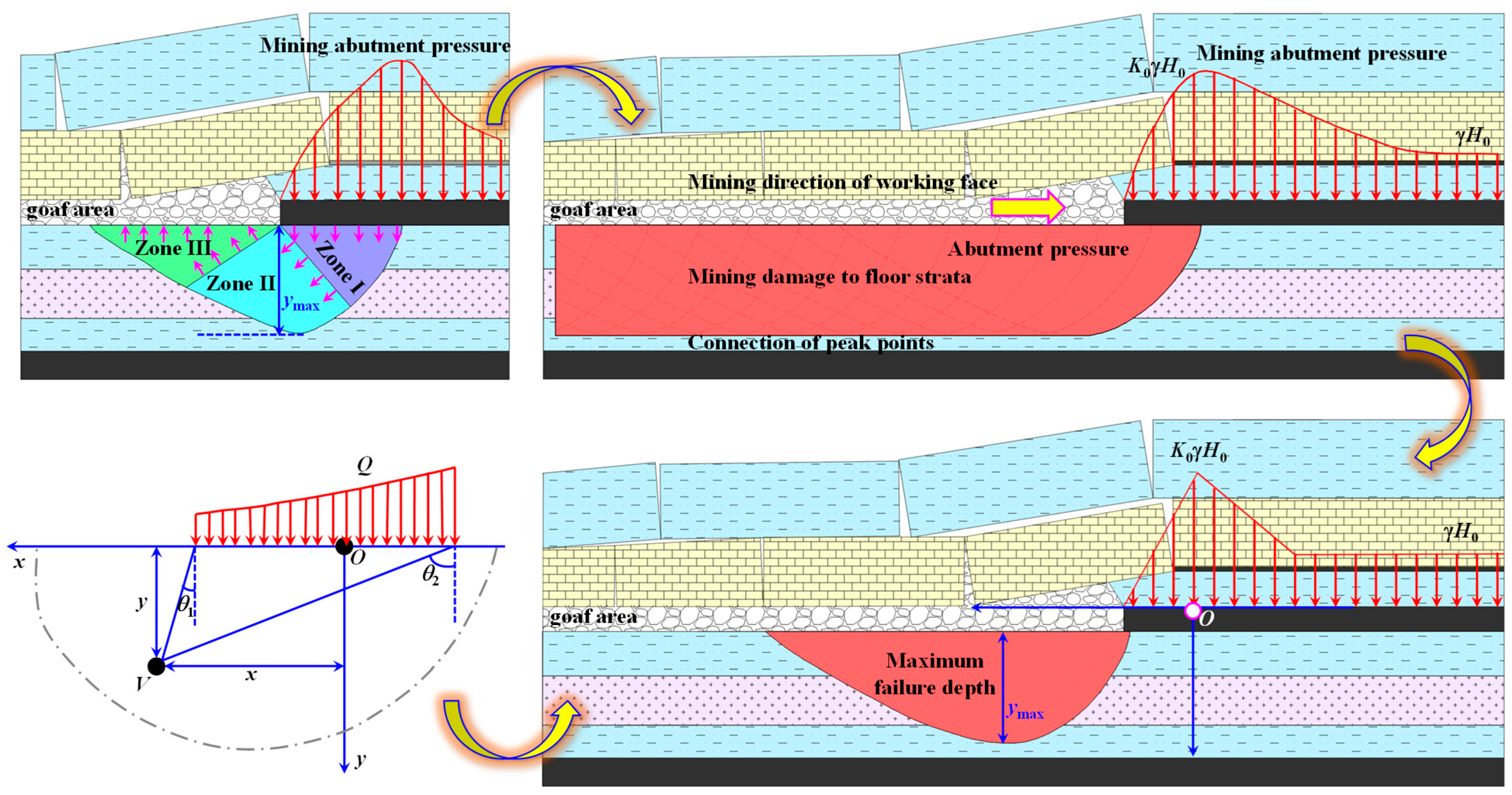
3. Theoretical Analysis for the Floor Ruin Depth after the UCS Mining

After the UCS is mined, the advanced stress of the panel will act on the rock mass within a certain depth range near the goaf floor. If the stress value is large enough to cause rock mass failure, the previously formed plastic deformation zone will become a complete failure zone and a continuous slip surface. The slip line field formed by the floor rock mass is shown in Figure 3. Zone I in Figure 3 represents the active limit zone, Zone II represents the transition zone, and Zone III represents the passive limit zone [26]. The mining of the panel is a continuous process, and as the panel continues to advance, the advanced stress moves forward with the panel. The maximum floor ruin depth at each stage is connected to form the ruin zone of the goaf floor.
In Figure 3, γHo represents the in situ stress; γ represents unit weight, KN/m3; Ho represents burial depth, m; KoγHo represents the peak value of the mining induced stress of panel; and Ko represents advanced mining concentration coefficient. The test mine has conducted on-site testing on the influence range and degree of advanced mining at similar geological conditions panel in the 2# coal seam using borehole stress gauges and obtained an advanced mining concentration coefficient of 2. According to reference [27], the linear load Q is simplified for calculation, as shown in Equation (1).
Q = γ ( 1 + K o ) H o 2
According to the theory of elasticity, the rock mass stress can be expressed as follows:
σ x = Q 1 2 π ( sin 2 θ 1 sin 2 θ 2 ) + 2 ( θ 1 + θ 2 ) σ y = Q 1 2 π ( sin 2 θ 2 sin 2 θ 1 ) + 2 ( θ 1 + θ 2 ) τ xy = τ yx = Q 1 2 π ( cos 2 θ 2 cos 2 θ 1 )
θ1 and θ2 represent the two angles between point V and the stress boundary, respectively. At any point, the floor principal stress is as follows:
σ 1 σ 3 = σ y + σ x 2 ± τ xy 2 + ( σ x σ y 2 ) 2
σ1 and σ3 are the maximum and minimum principal stresses at any point on the floor, respectively. According to the above equation, the expressions for the maximum and minimum principal stresses are as follows [26]:
σ 3 = y γ + Q 1 π ( sin θ 2 sin θ 1 ) + ( θ 2 + θ 1 ) σ 1 = y γ + Q 1 π ( sin θ 1 sin θ 2 ) + ( θ 2 + θ 1 )
Assuming that the failure of the rock mass conforms to the Mohr Coulomb yield criterion, the expression is as follows:
1 2 sin φ o ( σ 3 + σ 1 ) + cos φ o c o = 1 2 ( σ 3 + σ 1 )
In the formula, co represents the cohesive force, MPa; φo represents the internal friction angle, °. Therefore, the floor ruin depth caused by the UCS mining is as follows:
y = cos φ o c o sin φ o γ 1000 + Q ( sin θ sin φ o θ ) γ π 1000
Among them, θ1 + θ2 = θ, which can be obtained from Equation (6), is as follows: θ = arccos(sinφo). Therefore, the maximum floor ruin depth can be obtained as follows:
y max = cos φ o c o sin φ o γ 1000 + sin arccos ( sin φ o ) sin φ o arccos ( sin φ o ) 1 γ π 1000 Q
According to the geological conditions of the mine production, the geological parameters (co = 3.71 MPa, φo = 35°, Ho = 620 m, Ko =2, γ = 25 KN/m3) are substituted into Equation (7). According to the calculation results from the above equation, the maximum floor ruin depth caused by the UCS mining is about 16.1 m, which has already caused ruin to the LCS, and targeted technical measures need to be taken to reinforce the integrity of the LCS surrounding rock.

4. Numerical Analysis for GSER below near Distance Goaf

4.1. Establishment of Numerical Models

Based on the actual production geological conditions of the 2# and 3# coal seams, a FLAC3D model was constructed, as is shown in Figure 4.
The model dimension is x × y × z = 200 m × 300 m × 90 m. Assuming a rock bulk density of 25 kN/m3 and a gravitational acceleration of 9.81 m/s2, the failure for coal rock mass in the model follows the Mohr Coulomb constitutive model. The caving zone is not modeled, and the caving zone is simulated using natural collapse. The mining (excavation) sequence in this model is as follows: mining of the 2203 panel of the upper 2# coal seam → mining of the 2205 panel of the upper 2# coal seam → excavation of the air-return roadway of the 2303 panel of the lower 3# coal seam → mining of the 2303 panel of the lower 3# coal seam → construction of roadside filling wall → mining of the 2305 panel of the lower 3# coal seam. The coal rock mechanics parameters in numerical model are shown in Table 1.

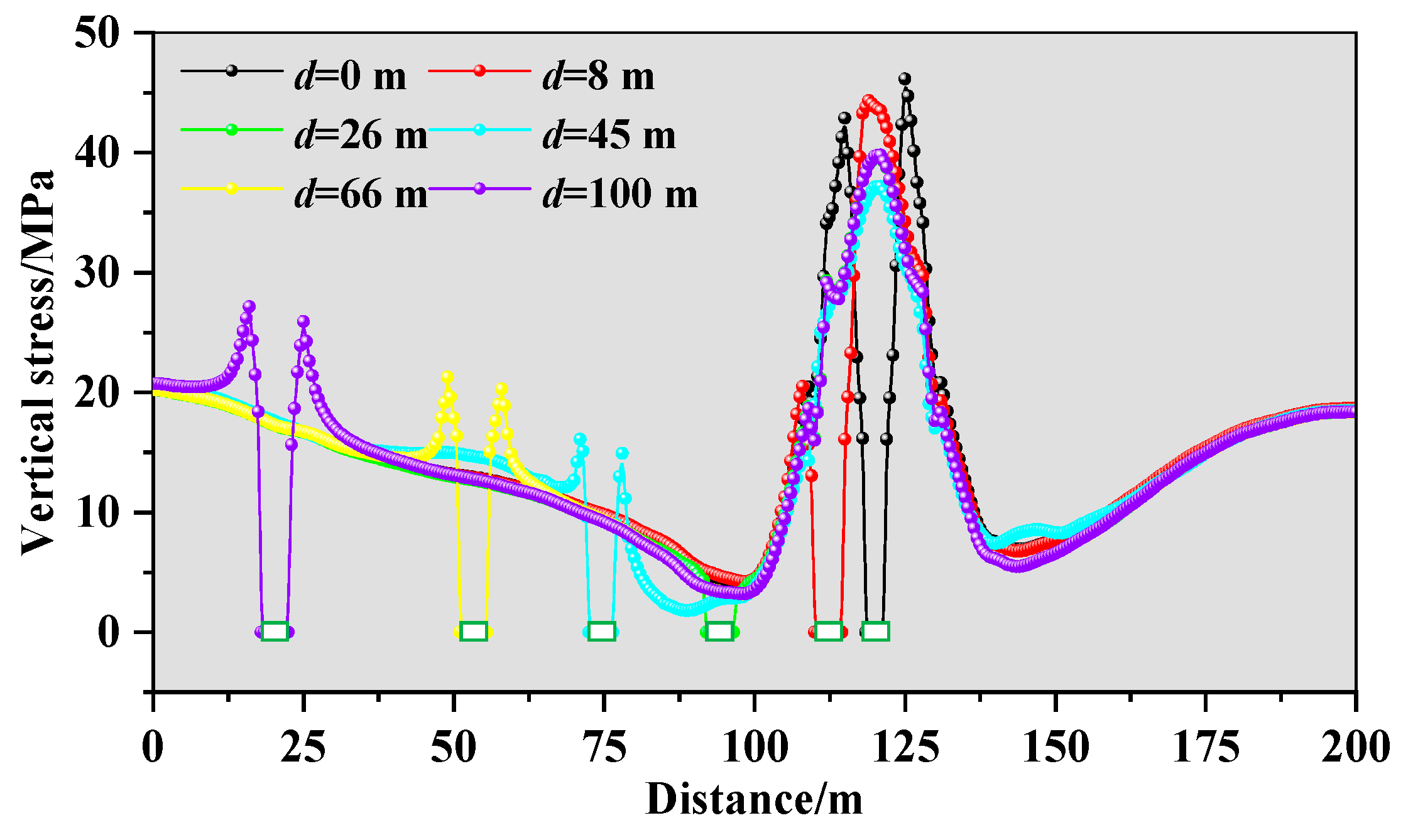
4.2. Stress Distribution Feature of the Goaf Floor after the UCS Mining

The stress distribution of the goaf floor after the UCS mining are shown in Figure 5.
According to the stress distribution feature in Figure 5, after the mining of the UCS panel, due to the 2203 panel excavated before the 2205 panel, resulting in a higher degree of compaction in the goaf of the 2203 panel, its stress level is generally higher than that of the 2205 goaf. For the floor of the 2205 goaf, there are obvious regional features of stress. The floor below the remaining coal pillar area is located in the stress high value zone (Zone A). A large area of stress extremely low zone (Zone B) is formed on the goaf floor near coal pillar. As it gradually moves away from the remaining coal pillar and approaches the deep part of the goaf, the stress in the floor gradually increases, forming a stress rebound zone (Zone C). However, the overall stress level in this zone is not high. Afterwards, as it approaches the middle of the goaf, the degree of goaf compaction gradually increases, and the stress gradually changes from the stress transition zone (Zone D) to the stress recovery zone (Zone E). The stress distribution features under different depths of the floor in each zone have significant differences: the stress in Zone A gradually decreases as the depth of the floor increases, the stress in Zone B gradually increases as the depth of the floor increases, the stress in Zone C gradually increases as the depth of the floor increases, the stress in Zone D gradually decreases as the depth of the floor increases, and the stress in Zone E gradually increases as the depth of the floor increases. In order to explore the stress and failure features of lower mining roadway arranged in different stress zones of the floor, Section 4.3 will conduct numerical simulation response research on the layout of mining roadway in different stress zones of the floor in the near distance goaf. The selection and layout of typical roadway positions within each stress zone are studied in this paper, that is, the distance between the center of the mining roadway and the center of the coal pillar, which are 0 m (d = 0 m, Zone A), 8 m (d = 8 m, Zone A), 26 m (d = 26 m, Zone B), 45 m (d = 45 m, Zone C), 66 m (d = 66 m, Zone D), and 100 m (d = 100 m, Zone E).

4.3. Analysis for the Layout of the GSER below near Distance Goaf

The cloud map and curve of the stress distribution at different positions of the GSER below near distance goaf are shown in Figure 6:
When the center of the roadway is 0 m away from the center of the coal pillar (d = 0 m), the roadway is located in Zone A. The center of the roadway coincides with the center point of the remaining coal pillar, and the roadway ribs are in a state of high concentrated stress. The stress on the left rib reaches 42.9 MPa, and the stress on the right rib reaches 46.1 MPa, with no significant difference in the roadway ribs stress. When the center of the roadway is 8 m away from the center of the coal pillar (d = 8 m), the roadway is located in Zone A. The left rib of the roadway coincides with the left rib of the remaining coal pillar, and the stress distribution of the roadway shows obvious asymmetry. The stress on the right rib of the roadway is in a large area of high stress, with a maximum stress value of 44.3 MPa, while the left rib of the roadway is in a lower stress state, with a maximum stress value of 20.5 MPa. From this, when arranging the roadway in the high stress value zone below the coal pillar, the roadway will be at a high stress level, and the stress level of one rib of the roadway near the center of the coal pillar is significantly higher than the other rib. A higher stress concentration level will not be conducive to the stability of the surrounding rock.
When the center of the roadway is 26 m away from the center of the coal pillar (d = 26 m), the roadway is located in Zone B. Both ribs of the roadway are in a low stress state. The stress on the left rib of the roadway is 4.3 MPa, and the stress on the right rib is 3.1 MPa. The difference in stress on the roadway ribs is not significant. So, when arranging the roadway in the extremely low stress zone, the mechanical properties and bearing capacity of the surrounding rock are poor, and the difficulty of controlling the surrounding rock is high.
When the center of the roadway is 45 m away from the center of the coal pillar (d = 45 m), the roadway is located in Zone C. The stress on both ribs of the roadway increases significantly compared to d = 26 m. The stress on the left rib of the roadway is 16.1 MPa, and the stress on the right rib is 14.9 MPa. The stress on both ribs of the roadway is relatively balanced, and the peak stress is at the level of the original rock stress. So, when arranging the roadway in the stress rebound area, the mechanical properties of the surrounding rock are good, and the stress peak is basically equivalent to the original rock stress, making it less difficult to control the surrounding rock.
When the center of the roadway is 66 m away from the center of the coal pillar (d = 66 m), the roadway is located in Zone D. The stress on both ribs of the roadway increases slightly compared to d = 45 m. The stress on the left rib of the roadway is 21.3 MPa, and the stress on the right rib is 20.3 MPa. The stress on both ribs of the roadway increases to varying degrees, and there is a relatively small degree of stress concentration on the roadway. When the center of the roadway is 100 m away from the center of the coal pillar (d = 100 m), the roadway is located in Zone E. The stress on both ribs of the roadway increases slightly compared to d = 66 m. The stress on the left rib of the roadway is 27.1 MPa, and the stress on the right rib is 25.9 MPa. The stress on both ribs of the roadway increases to varying degrees, and there is a relatively small degree of stress concentration on the roadway.
The summary of stress curves of surrounding rock at different positions of the GSER below near distance goaf are shown in Figure 7.

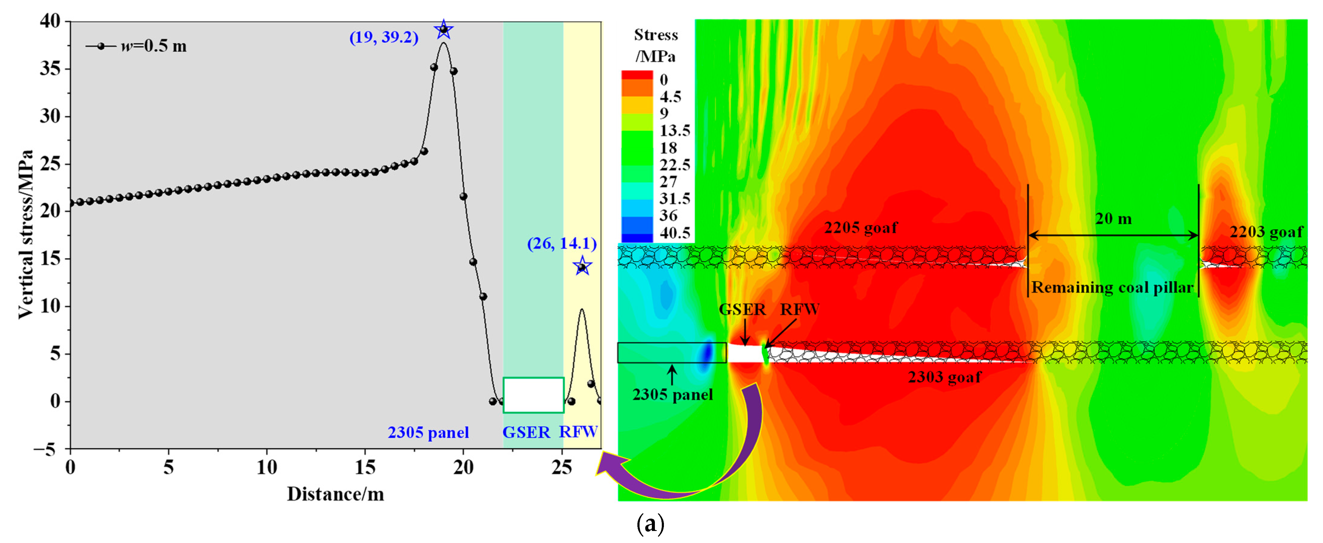
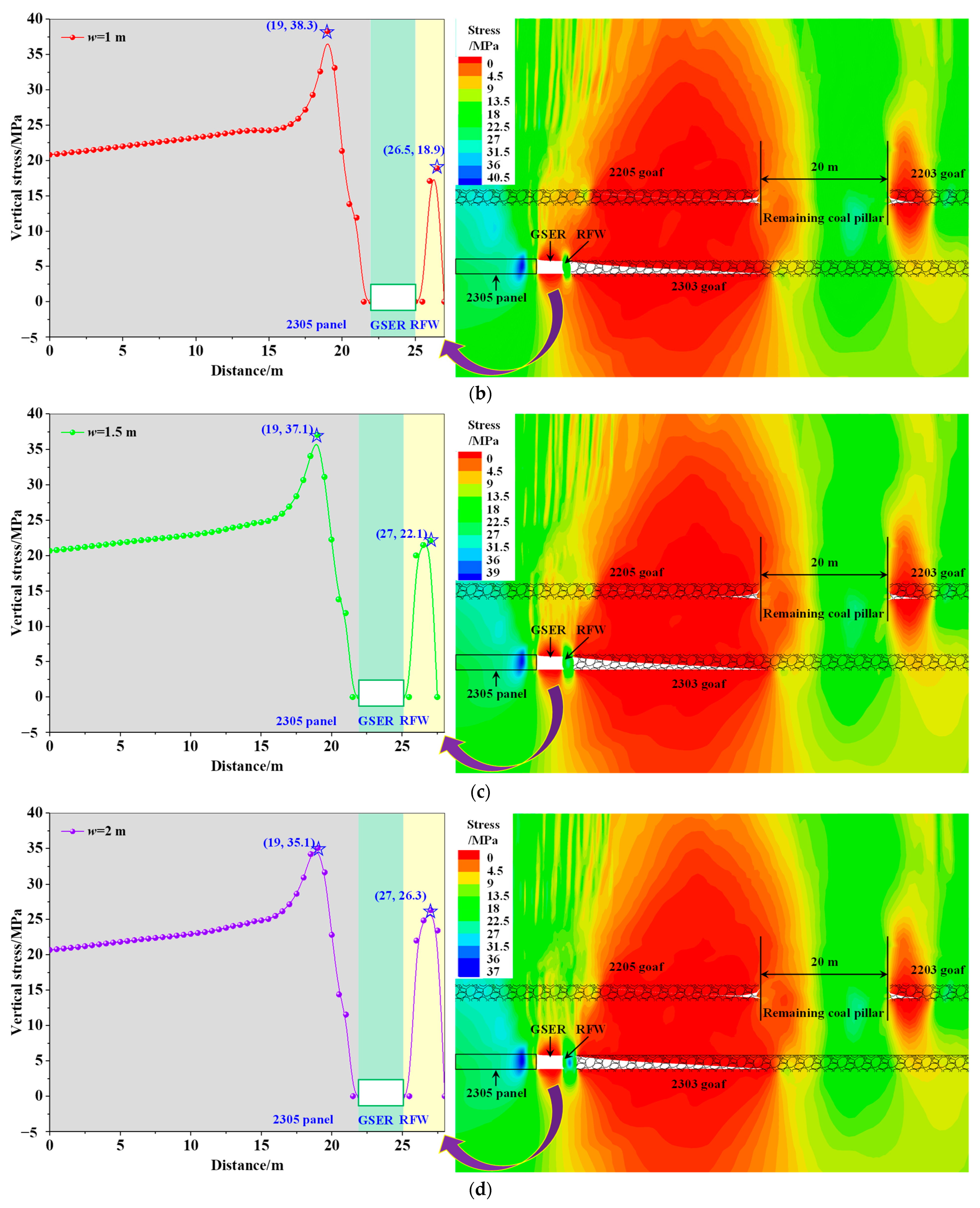
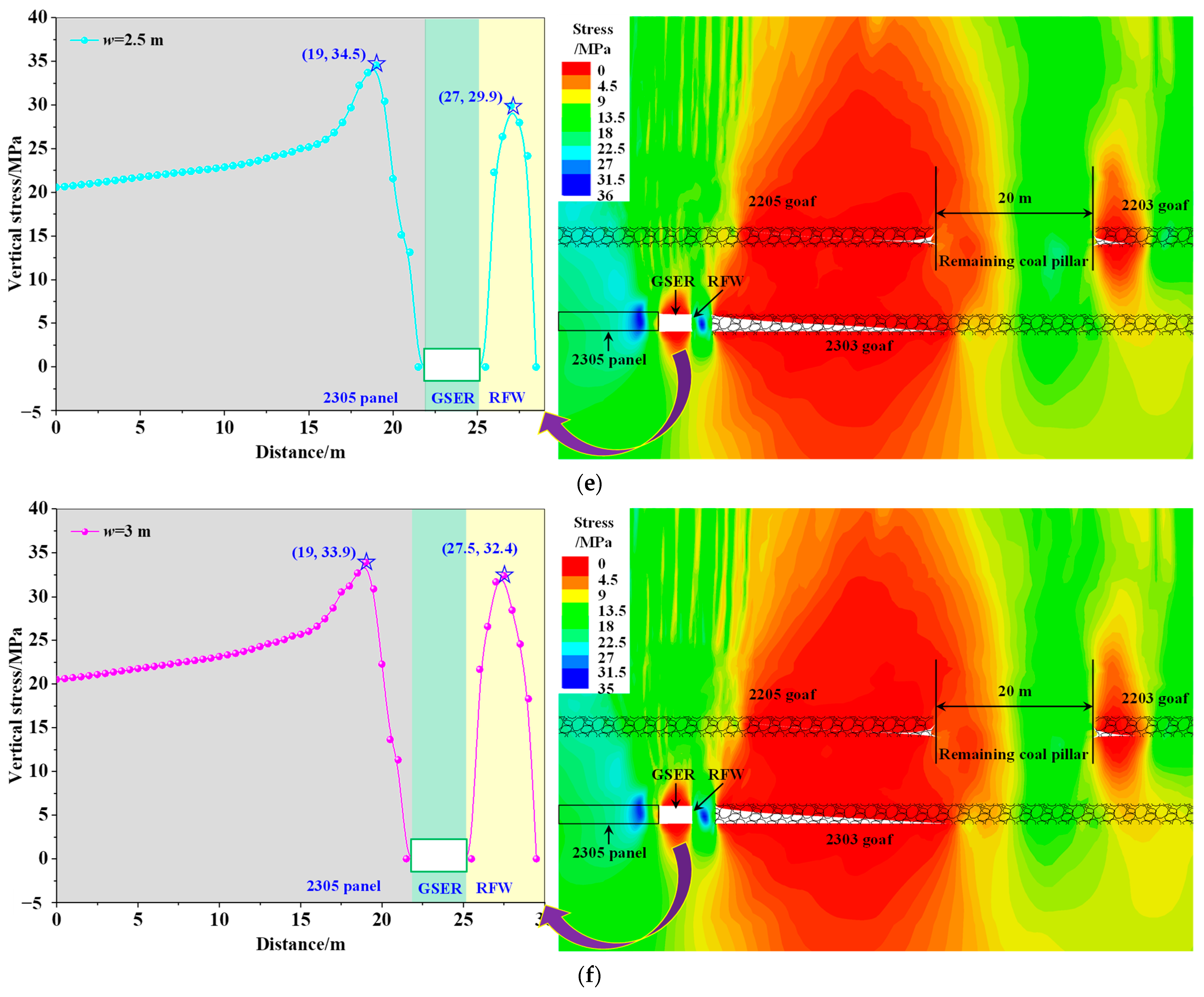
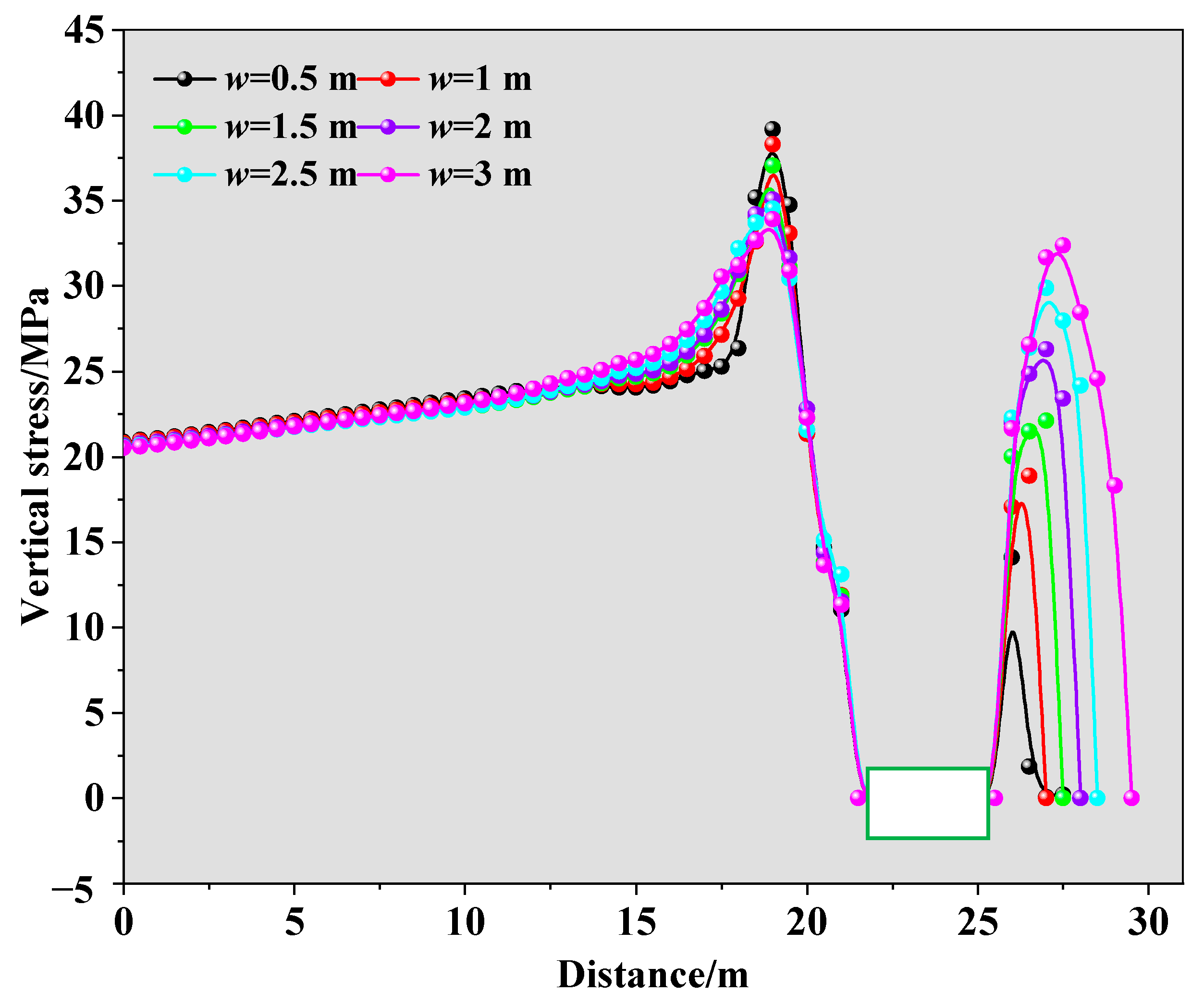
4.4. Analysis for the Width of the RFW below near Distance Goaf

The stress distribution cloud map and curve under different widths of the RFW of GSER below near distance goaf are shown in Figure 8. In this paper, w represents the width of the RFW.
According to Figure 8, the stress state on the GSER roof and floor basically does not change with the width of the RFW. The stress on the roof and floor under different RFW widths is in a wide range of low stress states. However, there are stress peaks on both RFW and the deep part of the solid coal rib under different widths of the RFW, and the stress concentration on the solid coal rib decreases with increasing RFW width, while the stress on the RFW increases with increasing RFW width.
When the width of the RFW increased from 0.5 m to 1 m, the stress value on the solid coal rib decreased from 39.2 MPa to 38.3 MPa, with a stress value decrease of 0.9 MPa. The stress of the RFW increased from 14.1 MPa to 18.9 MPa, with a stress value increase of 4.8 MPa. When the width of the RFW increased from 1 m to 1.5 m, the stress value on the solid coal rib decreased from 38.3 MPa to 37.1 MPa, with a stress value decrease of 1.2 MPa. The stress of the RFW increased from 18.9 MPa to 22.1 MPa, with a stress value increase of 3.2 MPa. When the width of the RFW increased from 1.5 m to 2 m, the stress value on the solid coal rib decreased from 37.1 MPa to 35.1 MPa, with a stress value decrease of 2 MPa. The stress of the RFW increased from 22.1 MPa to 26.3 MPa, with a stress value increase of 4.2 MPa. When the width of the RFW increased from 2 m to 2.5 m, the stress value on the solid coal rib decreased from 35.1 MPa to 34.5 MPa, with a stress value decrease of 0.6 MPa. The stress of the RFW increased from 26.3 MPa to 29.9 MPa, with a stress value increase of 3.6 MPa. When the width of the RFW increased from 2.5 m to 3 m, the stress value on the solid coal rib decreased from 34.5 MPa to 33.9 MPa, with a stress value decrease of 0.6 MPa. The stress of the RFW increased from 29.9 MPa to 32.4 MPa, with a stress value increase of 2.5 MPa.
The summary of stress curves of surrounding rock at different widths of the RFW of GSER below near distance goaf are shown in Figure 9:
When the RFW width is 0.5–1.5 m, the stress concentration phenomenon is more obvious on the solid coal rib, and the overlying rock pressure is mainly borne by the solid coal rib. The RFW is under less stress. Especially when the RFW width is 0.5 m, the bearing capacity is insufficient to support the overlying rock pressure. When the RFW width is 2–3 m, there is stress concentration on both the RFW and the solid coal rib. The RFW is subjected to increased stress, and its bearing capacity is significantly improved compared to 0.5–1.5 m. The RFW contributes to supporting the overlying rock layer. Balancing economic benefits, the RFW width is identified as 2 m.

5. Stability Control Technology of the GSER Surrounding Rock below near Distance Goaf

5.1. Control Ideas of the GSER Surrounding Rock below near Distance Goaf

As shown in Figure 10, control ideas of the GSER surrounding rock below near distance goaf are proposed mainly based on the following five aspects: reasonably arranging of the position of the LCS mining roadway, grouting modification of the coal and rock mass on the GSER roof, establishing a composite anchoring structure formed utilizing bolts (cables); strong support roof and control floor by one beam + three columns, reinforcing the RFW utilizing tie rods pre-tightening; and hydraulic prop protection RFW and bolts (cables) protection roof at roadside.
(1)
Reasonably arranging the position of the LCS mining roadway
The remaining protective coal pillars will generate concentrated stress, which will be transmitted along the floor to the LCS. When the roadway is arranged in the high stress area below the coal pillar, the superposition of high stress below the coal pillar and stress generated by roadway excavation will cause serious ruin to the surrounding rock. At the same time, when the roadway is arranged in the extremely low stress area below the goaf, the surrounding rock stress environment is poor, and its own bearing capacity is weak, which is not conducive to the stability of the roadway. Therefore, the roadway should be placed in a reasonable stress zone, namely the stress rebound zone.
(2)
Grouting modification of coal and rock mass on the GSER roof
Due to the fact that the distance between the 2# and 3# coal seams is only 11.5 m, and influenced by the occurrence of coal seams, the interlayer spacing in some areas is even smaller. When mining the UCS, it will cause multiple mining ruins to the roof of the LCS, and the integrity of the roof will be ruined before mining the LCS. This can easily lead to the fragmentation and collapse of the roof in some areas during the mining of the LCS. Therefore, it is necessary to promptly use hollow grouting anchor cables to modify and reinforce the roof of the roadway, laying the foundation for later support.
(3)
Establishing a composite anchoring structure formed utilizing bolts (cables)
The GSER surrounding rock has undergone multiple mining impacts from NDCS mining, and the ruin range is large. Therefore, it is necessary to provide reasonable active support for the surrounding rock with bolts (cables). By constructing a composite anchoring structure formed utilizing bolts (cables) in the GSER, the loose rock mass overlying the GSER can be supported to avoid further deterioration and deformation of the surrounding rock. The selection of anchor cable length is based on the principle of anchoring to a relatively stable coal rock mass to ensure the effectiveness of anchor cable anchoring. The stability of coal rock mass can be obtained by on-site drilling observation, and the higher the degree of crack development, the more unstable the coal rock mass. This article is based on on-site testing and determines that the length of the rib anchor cable is 4.5 m and the length of the roof anchor cable is 6.5 m.
(4)
Strong support roof and control floor by one beam + three columns
In view of the multiple dynamic pressure features of the GSER in the 2303 panel, relying solely on the active support of bolts (cables) is not reliable. A combination of active and passive forms support should be adopted to reinforce the GSER surrounding rock, thereby improving the overall stability of the GSER surrounding rock. Arranging a strong support system of one beam and three columns in the GSER can not only reinforce the composite load-bearing structure, suppress the bending deformation of the surrounding rock, but also effectively suppress the occurrence of floor heave phenomenon.
(5)
Reinforce the RFW utilizing tie rods pre-tightening, and hydraulic prop protection RFW and bolts (cables) protection roof at roadside
When the RFW width is 2–3 m, the RFW is subjected to increased stress, and its bearing capacity is significantly improved. The RFW contributes to supporting the overlying rock layer. Balancing economic benefits, the RFW width is identified as 2 m. The RFW of 2 m width belongs to the narrow wall, which is the key and difficult point for the reinforcement of the GSER surrounding rock. The RFW should be pre-tightened with a combination of tie rods and anchor plates, supplemented by hydraulic prop and bolts (cables) protection reinforcement technology, to limit the outward deformation of the RFW, effectively bear the load of the roof, and also achieve the effect of controlling the floor.

5.2. Control Mechanism of the GSER Surrounding Rock below near Distance Goaf

(1)
Grouting modification of coal and rock mass on the GSER roof
Due to the close proximity between the 2# and 3# coal seams, the integrity of the roof was ruined before the mining of the LCS. Therefore, it is necessary to promptly use hollow grouting long anchor cables to reinforce the GSER roof, increase the integrity and density of the surrounding rock of the roof, and provide favorable conditions for the functional performance of subsequent support components [28,29,30], ensuring that the anchor cables are firmly anchored and the initial support force of the hydraulic prop meets the standard. Therefore, grouting modification of the GSER roof is the foundation for achieving stability in the GSER.
(2)
Establishing a composite anchoring structure formed utilizing bolts (cables)
The main anchoring bearing structure formed by deep cables support and the secondary anchoring bearing structure formed by shallow bolts support in the GSER (see Figure 11a) are coupled with the surrounding rock to form a composite anchoring bearing structure, effectively controlling the expansion of the surrounding rock loosening zone and avoiding further deterioration of the roadway surrounding rock [31,32].
(3)
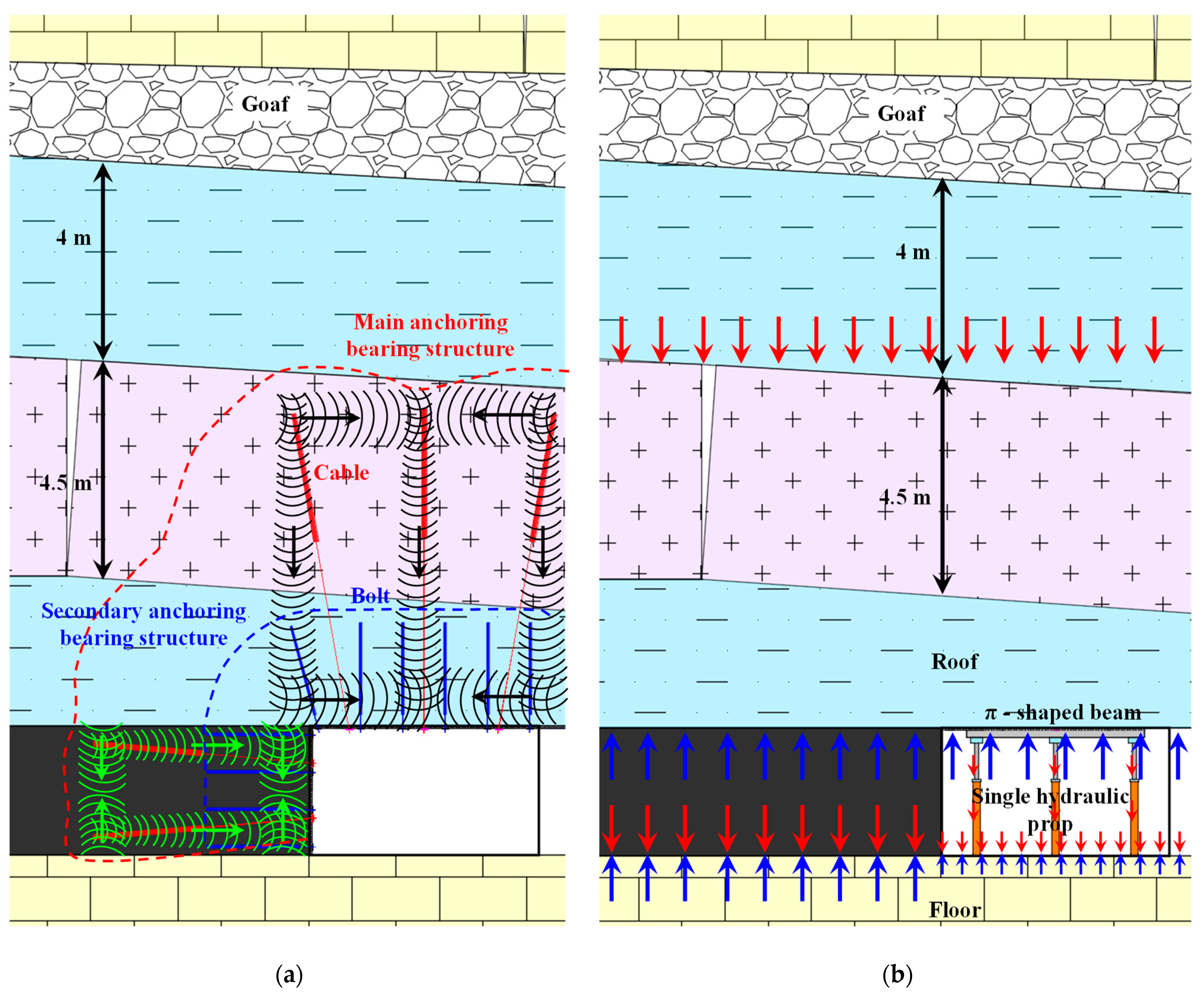
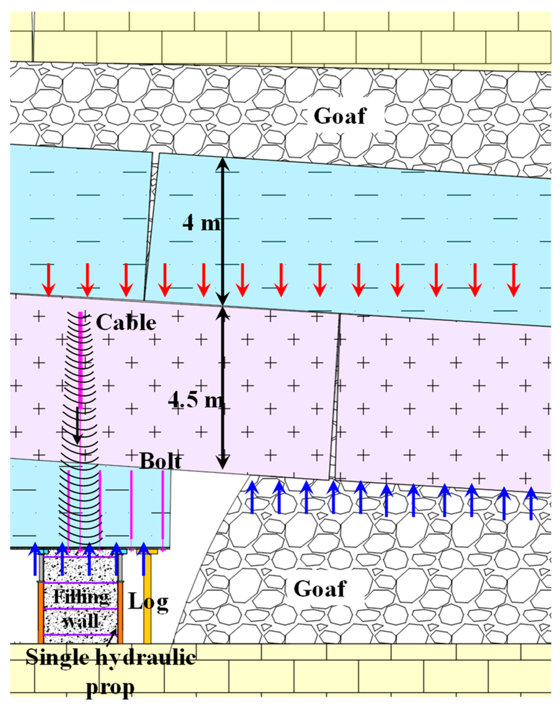
Strong support roof and control floor by one beam + three columns (see Figure 11b)
The application of π-shaped beams ensures uniform stress on the roof and strengthens the stability of the roof composite anchorage bearing structure. High resistance and compressibility hydraulic prop can provide high support resistance and achieve the purpose of span reduction. Hydraulic prop can adapt to deformation, achieving the goal of reducing the load on the roof. On the basis of bearing the load of the roof, the strong hydraulic prop can also serve as a transmission body to transfer the pressure of the roof to the floor and apply reverse restraining force to the floor, improving the support strength of the floor and achieving the effect of controlling the floor.
(4)
Reinforce the RFW utilizing tie rods pre-tightening, and hydraulic prop protection RFW and bolts (cables) protection roof at roadside (see Figure 12)
The combination of tie rods and anchor plates acting on the filling wall can effectively limit the outward extrusion deformation of the RFW, transforming the RFW from the original two-way stress state to a three-way stress state. The stress state inside the RFW is significantly improved, which can significantly enhance the bearing features of the RFW. As a temporary reinforcement support for RFW, the hydraulic prop can not only provide significant support resistance before the RFW is solidified, but also control the floor heave and jointly bear the roof load with the anchor cables applied on it.

5.3. Technology of GSER Support below near Distance Goaf

Based on the above control ideas and mechanisms, a comprehensive control technology for GSER surrounding rock below near distance goaf has been proposed, which includes the grouting modification of coal and rock mass on the GSER roof, establishing a composite anchoring structure formed utilizing bolts (cables); the strong support roof and control floor by one beam + three columns, reinforcing the RFW utilizing tie rods pre-tightening; and the hydraulic prop protection RFW and bolts (cables) protection roof at roadside, as shown in Figure 13.
The specifications of the roof bolts and ribs bolts are Φ 20 × 2200 mm, with a spacing of 850 × 800 mm between the roof bolts and 850 × 800 mm between the ribs bolts. The specifications of the roof cables and the ribs cables are Φ 21.8 × 6500 mm, with a spacing of 1500 × 1600 mm between the roof cables and 1100 × 1600 mm between the ribs cables. Among them, the roof cables adopts hollow grouting cables. The roof support of the GSER adopts the DW31.5–200/100X suspended hydraulic prop combined with a 3.6 m long π-shaped beam to form a “one beam and three columns” shed-style support. The width of the RFW is 2 m, and the spacing between the tie rods in RFW is 700 × 800 mm. In addition, to prevent gas exceeding the limit, a DN100 drainage pipe should be pre-embedded on the RFW every 6 m, 400 mm away from the roof, to extract gas from the goaf.

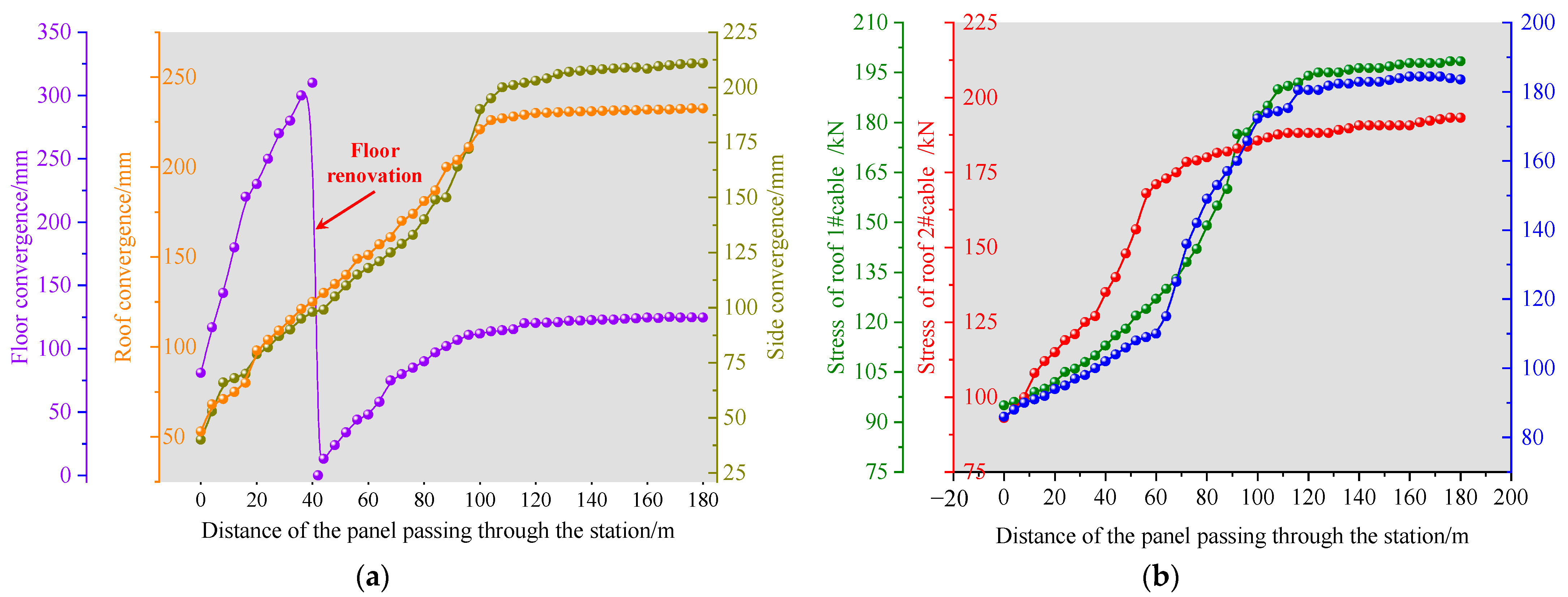
5.4. Effect Analysis for GSER Support below near Distance Goaf

After the completion of 50 m of filling wall construction, the first measuring station will be set up to monitor the deformation of the roadway and the stress on the supporting structure, and then every 30 m, a measuring station will be set up. Monitor the deformation of the surrounding rock and the stress on the anchor cables as the panel gradually moves away from the monitoring station. The manual method is used for mining pressure observation, and mining pressure observation is conducted on-site every 2 days. Due to the limited length of the article, the mining pressure monitoring data under typical monitoring stations is selected, as shown in Figure 14.
When the panel is pushed over 100 m, the deformation of the surrounding rock and the force on the anchor cable tend to stabilize, which is the stable stage of deformation and force on the surrounding rock. At this time, the maximum displacement of the roof and the force on the anchor cable are achieved, with a total displacement of less than 240 mm and an anchor cable force of less than 210 kN. The mining pressure data are in a healthy state.
In order to evaluate the development of internal cracks in the surrounding rock, drilling observations were conducted on the roof and ribs of GSER, which had been pushed over 80 m from the panel, as shown in Figure 15.
There are relatively fragmented areas within a depth range of 2.2 m in the roadway rib. At a depth of 3.2 m, the degree of coal ruin in the roadway rib decreases, but the cracks are still relatively developed. At a depth of 4 m, the coal is relatively intact. The control technology on the roadway rib can effectively limit the development and expansion of the roadway cracks, making the roadway cables to anchor in a relatively stable area. For the GSER roof, the rock mass within a depth range of 3 m is relatively fragmented. At a depth of 5.2 m, there is mild crack development in the rock mass, but the overall integrity of the rock mass is good, and the anchoring effect of the long anchor cable on the roof is good.
It can be seen that the above-mentioned technology effectively limits the collapse and subsidence of the roof and the lateral extrusion deformation of the RFW. The GSER test project has been successful.

6. Conclusions

(1)
The floor below the remaining coal pillar area is located in the stress high value zone (Zone A). A large area of stress extremely low zone (Zone B) is formed on the goaf floor near coal pillar. As it gradually moves away from the remaining coal pillar and approaches the deep part of the goaf, the floor forms a stress rebound zone (Zone C) and the overall stress level in this zone is not high. Afterwards, as it approaches the middle of the goaf, the degree of goaf compaction gradually increases, and the stress gradually changes from the stress transition zone (Zone D) to the stress recovery zone (Zone E). The stress distribution features at different depths of the goaf floor in each zone also have differences.
(2)
Arranging the roadway in Zone A below the coal pillar, the roadway is at high stress levels, which is not conducive to the stability of the surrounding rock. Arranging the roadway in Zone B below the goaf floor, the mechanical properties and bearing capacity of the surrounding rock are poor, making it difficult to control the surrounding rock. Arranging the roadway in Zone C, the mechanical properties of the surrounding rock are good, and the difficulty of controlling the surrounding rock is relatively low. Arranging the roadway in Zone D and Zone E, there is a relatively small degree of stress concentration in the roadway rib.
(3)
When the RFW width is 0.5–1.5 m, the stress concentration phenomenon is more obvious on the solid coal rib, and the overlying rock pressure is mainly borne by the solid coal rib. The RFW is under less stress. Especially when the RFW width is 0.5 m, the bearing capacity is insufficient to support the overlying rock pressure. When the RFW width is 2–3 m, there is stress concentration on both the RFW and the solid coal rib. The RFW is subjected to increased stress, and its bearing capacity is significantly improved compared to 0.5–1.5 m. The RFW contributes to supporting the overlying rock layer. Balancing economic benefits, the RFW width is identified as 2 m.
(4)
A comprehensive control technology for GSER surrounding rock below near distance goaf has been proposed, which includes the grouting modification of coal and rock mass on the GSER roof, establishing a composite anchoring structure formed utilizing bolts (cables); the strong support roof and control floor by one beam + three columns, reinforcing the RFW utilizing tie rods pre-tightening; and the hydraulic prop protection RFW and bolts (cables) protection roof at roadside. On-site practice has proven that this technology effectively maintains the integrity of the GSER cross-section.

Author Contributions

Writing—original draft preparation, Z.J. and L.Z.; writing—review and editing, Z.J. and D.C.; supervision, S.X. and Z.Y.; funding acquisition, S.X and D.C. All authors have read and agreed to the published version of the manuscript.

Funding

This research was supported by the Fundamental Research Funds for the Central Universities (Ph.D. Top Innovative Talents Fund of CUMTB) (No. BBJ2024007) and the National Natural Science Foundation of China (No. 52074296 and 52004286).

Data Availability Statement

The datasets generated or analyzed during the current study are available from the corresponding author on reasonable request.

Acknowledgments

The author team thanks the field technicians for providing the field test conditions and the ground pressure observation conditions.

Conflicts of Interest

Author Zhiqiang Yan was employed by the Shanxi Coking Coal Fenxi Mining Group Co., Ltd. The remaining authors declare that the research was conducted in the absence of any commercial or financial relationships that could be construed as a potential conflict of interest.

References

  1. Peng, N.B.; Zhang, C.L.; Feng, R.M.; Arif, A.; Chen, X.; Zhang, W.D.; Zhang, S.; Feng, M.J. Analysis of dynamic evolution of surrounding rock movement and stress-fracture in the upward and repeated mining of close-distance coal seams. Adv. Civ. Eng. 2024, 2024, 5548837. [Google Scholar] [CrossRef]
  2. Wang, X.F.; Wang, J.Y.; Chen, X.Y.; Chen, Z.C. A roadway in close distance to coal seam in deep mine: Location selection and supporting practice based on creep features of surrounding rocks. Arch. Min. Sci. 2021, 66, 407–419. [Google Scholar]
  3. Cui, F.; Jia, C.; Lai, X.P.; Yang, Y.B.; Dong, S. Study on the law of fracture evolution under repeated mining of close-distance coal seams. Energies 2020, 13, 6064. [Google Scholar] [CrossRef]
  4. Gao, K.; Huang, P.; Liu, Z.G.; Liu, J.; Wang, F.; Shu, C.M. Pressure relief by blasting roof cutting in close seam group mining under thick sandstone to enhance gas extraction for mining safety. Processes 2021, 9, 603. [Google Scholar] [CrossRef]
  5. Chen, D.D.; Wu, Y.Y.; Xie, S.R.; Guo, F.F.; He, F.L.; Liu, R.P. Reasonable location of stopping line in close-distance underlying coal seam and partition support of large cross-section roadway. Int. J. Coal Sci. Technol. 2022, 9, 55. [Google Scholar] [CrossRef]
  6. Chen, D.D.; Ma, X.; Wu, Y.Y.; Xie, S.R.; Li, H.; Jiang, Z.S.; Wang, E.; Guo, F.F.; Guo, W.K.; Ye, Q.C. Failure mechanism and divisional differentiated control of surrounding rock in mining roadway under remaining coal pillar in close-distance coal seam. Energy Sci. Eng. 2023, 11, 1412–1435. [Google Scholar] [CrossRef]
  7. Xie, S.R.; Wu, Y.Y.; Guo, F.F.; Chen, D.D.; Wang, E.; Zhang, X.; Zou, H.; Liu, R.P.; Ma, X.; Li, S.J. Interaction mechanism of the upper and lower main roofs with different properties in close coal seams: A case study. Energies 2022, 15, 5533. [Google Scholar] [CrossRef]
  8. Geng, D.Y.; Fan, L.J.; Du, Y.T.; Zhu, Q.W.; Li, T.C.; Zhao, J.W. Research on the mechanism and control of roof deformation in gob-side entry retaining of close-distance coal seams. Eng. Fail. Anal. 2024, 164, 108682. [Google Scholar] [CrossRef]
  9. Xie, S.R.; Wang, E.; Chen, D.D.; Li, H.; Jiang, Z.S.; Yang, H.Z. Stability analysis and control technology of gob-side entry retaining with double roadways by filling with high-water material in gently inclined coal seam. Int. J. Coal Sci. Technol. 2022, 9, 52. [Google Scholar] [CrossRef]
  10. Xie, S.R.; Pan, H.; Chen, D.D.; Zeng, J.C.; Song, H.Z.; Cheng, Q.; Xiao, H.B.; Yan, Z.Q.; Li, Y.H. Stability analysis of integral load-bearing structure of surrounding rock of gob-side entry retention with flexible concrete formwork. Tunn. Undergr. Space Technol. 2020, 103, 103492. [Google Scholar] [CrossRef]
  11. Nie, B.S.; Zhang, H.; Liu, X.F.; Li, Y.; Deng, B.Z.; He, H.Y.; Liu, P. Experimental study on the mechanical stability and mesoscopic damage characteristics of coal under different mining disturbance rates. Rock Mech. Rock Eng. 2024, 57, 3841–3861. [Google Scholar] [CrossRef]
  12. Liu, W.; Cheng, W.X.; Liu, X.F.; Zhang, Z.Q.; Yue, Z.W.; Yang, L.Y.; Shen, A. Effects of loading rate and notch geometry on dynamic fracture behavior of rocks containing blunt v-notched defects. Rock Mech. Rock Eng. 2024, 57, 2501–2521. [Google Scholar] [CrossRef]
  13. Li, L.W.; Liu, X.F.; Nie, B.S.; Sun, H.T.; Jia, X.Q.; Zhang, C.P. Microstructural alterations of coal induced by interaction with sequestered supercritical carbon dioxide. Energy 2024, 304, 131912. [Google Scholar] [CrossRef]
  14. Wu, X.Y.; Wang, S.; Gao, E.R.; Chang, L.; Ji, C.X.; Ma, S.J. Failure mechanism and stability control of surrounding rock in mining roadway with gentle slope and close distance. Eng. Fail. Anal. 2023, 152, 107489. [Google Scholar] [CrossRef]
  15. Liu, H.Y.; Zuo, J.P.; Zhang, C.W.; Wu, K.J.; Lei, B. Asymmetric deformation mechanism and control technology of roadway under room-pillar group in Huasheng coal mine. J. Cent. South Univ. 2023, 30, 2284–2301. [Google Scholar] [CrossRef]
  16. Yan, H.; Weng, M.Y.; Feng, R.M.; Li, W.K. Layout and support design of a coal roadway in ultra-close multiple-seams. J. Cent. South Univ. 2015, 22, 4385–4395. [Google Scholar] [CrossRef]
  17. Wu, X.Y.; Nan, Z.; Chen, D.D.; Wu, X.W.; Zhou, H. Coupling support technique for coal roadway under double gobs in close coal seams. Energy Sci. Eng. 2024, 12, 2385–2404. [Google Scholar] [CrossRef]
  18. Cao, Y.X.; Zhang, J.P.; Yang, T.; Chu, H.B.; Zhang, X.; Zhang, T. Mechanism and application of prestressed yielding support for large-span roadway in multistress concentration areas. Processes 2023, 11, 1600. [Google Scholar] [CrossRef]
  19. Xiong, Y.; Kong, D.Z.; Cheng, Z.B.; Wen, Z.J.; Ma, Z.Q.; Wu, G.Y.; Liu, Y. Instability control of roadway surrounding rock in close-distance coal seam groups under repeated mining. Energies 2021, 14, 5193. [Google Scholar] [CrossRef]
  20. Hu, C.W.; Yang, X.J.; Li, Q.; Hu, B.; Li, Y.Y.; Jiang, Q.; Sun, F.L. Key parameters of gob-side entry retaining by roof cutting in close-distance seam group. Geomech. Geophys. Geo-Energy Geo-Resour. 2024, 10, 55. [Google Scholar] [CrossRef]
  21. Yin, S.F.; Zheng, X.J.; Wang, E.; Kang, Q.T.; Zhang, X.M. Non-uniform failure and differential pressure relief technology of roadway under irregular goafs in deep close-distance coal seams. Sci. Rep. 2023, 13, 18527. [Google Scholar] [CrossRef] [PubMed]
  22. Lv, K.; He, F.L.; Li, L.; Xu, X.H.; Qin, B.B. Field and simulation study of the rational retracement channel position and control strategy in close-distance coal seams. Energy Sci. Eng. 2022, 10, 2317–2332. [Google Scholar] [CrossRef]
  23. Wang, H.; Shuang, H.; Li, L.; Xiao, S. The stability factors’ sensitivity analysis of key rock b and its engineering application of gob-side entry driving in fully- mechanized caving faces. Adv. Civ. Eng. 2021, 2021, 9963450. [Google Scholar] [CrossRef]
  24. Shang, H.F.; Ning, J.G.; Hu, S.C.; Yang, S.; Qiu, P.Q. Field and numerical investigations of gateroad system failure under an irregular residual coal pillar in close-distance coal seams. Energy Sci. Eng. 2019, 7, 2720–2740. [Google Scholar] [CrossRef]
  25. Yang, S.; Li, Q.; Yue, H.; Kong, D.; Wu, G.; Yang, S.; Liu, F. Study on roof deformation and failure law of NDCS mining based on digital image correlation. Exp. Tech. 2024, 48, 757. [Google Scholar] [CrossRef]
  26. Liu, W.T.; Mu, D.R.; Yang, L.; Li, L.-Y.; Shi, C.-H. Calculation method and main factor sensitivity analysis of inclined coal floor ruin depth. J. China Coal Soc. 2017, 42, 849–859. [Google Scholar]
  27. Lu, H. Stress distribution and failure depths of layered rock mass of mining floor. Chin. J. Rock Mech. Eng. 2014, 33, 2030–2039. [Google Scholar]
  28. Xie, S.R.; Jiang, Z.S.; Chen, D.D.; Wang, E.; Lv, F. A new pressure relief technology by internal hole-making to protect roadway in two sides of deep coal roadway: A case study. Rock Mech. Rock Eng. 2022, 56, 1537–1561. [Google Scholar] [CrossRef]
  29. Chen, D.D.; Jiang, Z.S.; Ma, X.; Xie, S.R.; Wang, E.; Li, H. Evolution law and engineering application on main stress difference for a novel stress relief technology in two ribs on deep coal roadway. J. Cent. South Univ. 2023, 30, 2266–2283. [Google Scholar] [CrossRef]
  30. Li, Y.L.; Yang, R.S.; Fang, S.Z.; Lin, H.; Lu, S.J.; Zhu, Y.; Wang, M.S. Failure analysis and control measures of deep roadway with composite roof: A case study. Int. J. Coal Sci. Technol. 2022, 9, 2. [Google Scholar] [CrossRef]
  31. Yu, W.; Li, K.E.; Zhou, Z. Deformation mechanism and control technology of surrounding rock in the deep-buried large-span chamber. Geofluids 2020, 2020, 8881319. [Google Scholar] [CrossRef]
  32. Zhan, Q.J.; Shahani, N.M.; Zheng, X.G.; Xue, Z.C.; He, Y.Y. Instability mechanism and coupling support technology of full section strong convergence roadway with a depth of 1350 m. Eng. Fail. Anal. 2022, 139, 106374. [Google Scholar] [CrossRef]
Figure 1. Layout of the NDCS panel.
Processes 12 01966 g001
Figure 2. Lithological distribution in the panel area.
Processes 12 01966 g002
Figure 3. Principle diagram of floor sliding failure.
Processes 12 01966 g003
Figure 4. Numerical model.
Processes 12 01966 g004
Figure 5. Stress distribution of goaf floor after UCS mining.
Processes 12 01966 g005
Figure 6. Cloud map and curve of surrounding rock stress at different roadway positions below near distance goaf. (a) d = 0 m, (b) d = 8 m, (c) d = 26 m, (d) d = 45 m, (e) d = 66 m, (f) d = 100 m.
Processes 12 01966 g006aProcesses 12 01966 g006b
Figure 7. Summary of stress curves of surrounding rock at different roadway positions near distance goaf.
Processes 12 01966 g007
Figure 8. Cloud map and curve of surrounding rock stress at different RFW width below near distance goaf. (a) w = 0.5 m, (b) w = 1 m, (c) w = 1.5 m, (d) w = 2 m, (e) w = 2.5 m, (f) w = 2 m.
Processes 12 01966 g008aProcesses 12 01966 g008bProcesses 12 01966 g008c
Figure 9. Summary of stress curves of surrounding rock at different RFW width below near distance goaf.
Processes 12 01966 g009
Figure 10. Control ideas for GSER surrounding rock below near distance goaf.
Processes 12 01966 g010
Figure 11. Composite anchoring structure and one beam and three columns system. (a) Composite anchoring structure, (b) one beam and three columns system.
Processes 12 01966 g011
Figure 12. Roadside filling structure.
Processes 12 01966 g012
Figure 13. Comprehensive control technology for GSER surrounding rock of below near distance goaf. (a) Plan of comprehensive control technology, (b) sectional drawing of comprehensive control technology.
Processes 12 01966 g013
Figure 14. Deformation of surrounding rock and stress on anchor cables of gob-side entry retaining. (a) Deformation of surrounding rock, (b) stress on anchor cables.
Processes 12 01966 g014
Figure 15. Observation results of drilling holes inside the roof and rib of GSER. (a) At a depth of 1.28 m at roadway rib, (b) at a depth of 2.15 m at roadway rib, (c) at a depth of 3.16 m at roadway rib, (d) at a depth of 4 m at roadway rib, (e) at a depth of 1.2 m at roadway roof, (f) at a depth of 3 m at roadway roof, (g) at a depth of 5.2 m at roadway roof, (h) at a depth of 6.2 m at roadway roof.
Processes 12 01966 g015
Table 1. Actual physical and mechanical properties of each stratum.
Rock Stratum D /kg·m−3 K /GPa G /GPa φ m C m /MPa σ tm /MPa
Upper rock layer27206.687.52323.422.41
Sandy mudstone25006.725.13303.112.33
Siltstone26207.336.14343.392.34
Fine sandstone26706.525.37353.712.57
Coal14405.114.49222.311.92
Quartz sandstone22007.255.81302.812.42
Mudstone25406.455.12282.692.28
Lower rock layer27307.416.15333.512.40
σ tm represents the tensile strength, D represents the density, G represents the shear modulus, K represents the bulk modulus, φ m represents the friction angle, C m represents the cohesion.
Disclaimer/Publisher’s Note: The statements, opinions and data contained in all publications are solely those of the individual author(s) and contributor(s) and not of MDPI and/or the editor(s). MDPI and/or the editor(s) disclaim responsibility for any injury to people or property resulting from any ideas, methods, instructions or products referred to in the content.

