Abstract
This study delves into the convective heat transfer phenomena within a square cavity that houses a porous medium, analyzing the effects of Darcy (Da) and Rayleigh (Ra) numbers on the thermal and fluid dynamic behavior within the system. Utilizing a combination of computational fluid dynamics (CFD) and the finite element method (FEM), the research focuses on steady-state, laminar flow conditions in two dimensions. The cavity, which is impermeable at its boundaries, contains a centrally located square region filled with a porous, isotropic material. The thermal environment is controlled with insulated horizontal walls and vertically positioned walls that experience sinusoidal temperature variations. The study examines how variations in the permeability of the porous medium (Da numbers ranging from 10−1 to 10−4) and the buoyancy-driven flow strength (Ra numbers spanning from 102 to 105) influence the velocity fields and heat transfer rates, with results expressed through Nusselt number (Nu) distributions. The findings reveal that higher Ra numbers, particularly at 105, significantly intensify convection within the cavity, thereby boosting local rates of heat transfer, especially in the central vertical section. The research identifies that optimal flow resistance in the porous medium occurs within the Da number range of 10−3 to 10−4. These insights are critical for advancing thermal management techniques, particularly in the natural cooling of electronic devices and improving insulation methods.
1. Introduction
The study of heat transfer (HT) and fluid flow (FF) within porous media (PM) has been the subject of extensive research due to its complex behaviors. Scholars such as Xu et al. [1], Kaviany [2], Tien & Vafai [3], and Vafai & Tien [4] have thoroughly examined these intricate processes, shedding light on the mechanisms that govern thermal and fluid movement in PM.
Investigations by Mekroussi et al. [5] and Walker & Homsy [6] have examined the mixed convection interaction in various cavity configurations. Mekroussi et al. [5] utilized a cavity with a moving lid, wavy walls, and uneven heating to enhance HT. In contrast, Walker & Homsy [6] analyzed convection in cavities with isothermal vertical walls. Their advanced cavity designs and comprehensive approaches have provided valuable insights into HT characteristics within PM. Additionally, Kumar et al. [7] focused on the complex interaction between miscible viscous fingering and PM. Their COMSOL simulations detailed the complexities of FF in uniform PM. Baytas & Pop [8] addressed convection challenges in shallow cavities by applying matched asymptotic expansions to yield solutions suitable for specific geometries. Recent studies, including those by Saidi et al. [9], have investigated how incompressible air behaves in PM, examining the impact of sinusoidal thermal fluctuations on HT. Saeid’s [10]’s study on natural convection with spatial sinusoidal temperature variations further enriched the understanding of HT in porous cavities.
Muyungi [11] demonstrated that incorporating nanofluids into PM significantly enhances convective HT. Their investigation of copper- and alumina-based nanofluids revealed considerable improvements in HT efficiency, particularly in porous pipes subjected to Navier slip conditions. Menni et al. [12] reviewed methods to enhance HT and FF in PM, focusing on turbulators and applications such as heat exchangers. Huang et al. [13] employed flow visualization techniques, HT analysis, and large-eddy simulations to investigate the dynamics within periodically PM. Nabwey et al. [14] examined thermal dynamics in PM using nanofluids and applied various analytical techniques to characterize the fluid movement and thermal behavior across diverse PM. This study also summarizes future research directions and conducts a detailed examination of statistical outcomes derived from reviewed investigations, focusing on factors such as nanofluid types and the geometrical characteristics of the flow domain. In a related study, Douha et al. [15] partitioned a differently heated cavity into two sections: one containing a mixture of Al2O3 and water, and the other containing pure water. A porous conductive wall, characterized by its thickness and thermal conductivity, served as the interface between the two sections. Their findings indicated that increasing the Rayleigh number (Ra), Darcy number (Da), and volume fraction (φ) improved performance on the cold wall of the cavity.
Li et al. [16] performed an in-depth study on improving HT and mass dynamics via convection resonance in compartments filled with various PM. Their study explored a range of parameters across domains dominated by natural, mixed, and forced convection. Key parameters examined included buoyancy ratio, permeability, Richardson number, Reynolds number (Re), enclosure tilt, thermal conductivity, and frequency. The findings revealed that decreasing permeability in a vertical enclosure and increasing the Richardson-to-floating force ratio significantly improved transfer rates. Additionally, the use of dense PM and the balancing of buoyancy forces were found to reduce total entropy production. Continuing in this area, Liu et al. [17] investigated convective HT dynamics in PM using digital rock technology to analyze three-dimensional (3D) pore structures. They proposed an innovative method for determining hydraulic characteristic sizes and explored HT properties under varying pressure drop conditions. Their analysis highlighted distinct inlet behaviors, characterized by the determination of local Nusselt numbers (Nu) and convective HT coefficients.
Through the analysis of various parameters and boundary conditions, these studies collectively enhance the comprehension of HT mechanisms in PM. This progress paves the way for innovative applications in engineering and environmental sciences, as demonstrated by Lauriat & Ghafir [18], Chu et al. [19], and Shenoy [20]. Zhu et al. [21] specifically investigated the role of endothermic hydrocarbon fuels in managing the thermal conditions of hypersonic scramjets. Their goal was to understand the internal flow characteristics of kerosene-fueled scramjet combustors and assess their design performance as a viable alternative for economical scramjets operating at Mach numbers (Ma) between 4 and 8. Employing a two-dimensional (2D) cooling channel simulation with a specialized global chemical kinetic model, the study incorporated PM to explore the expansion of the overall cold source provided by hydrocarbon fuels. The findings indicated that increasing the porosity of the cooling channel could enhance HT and mitigate thermal stratification compared to smooth channels.
The oil and gas industry heavily depends on air-cooled heat exchangers (ACHEs), which have been extensively studied through various analytical techniques. However, many of these methods are constrained by their limited scope or accuracy. Younus et al. [22] proposed an advanced modeling approach for ACHEs that integrates real geometric designs, presenting a more comprehensive method compared to traditional approaches. By incorporating the entire length of the U-shaped tube and PM into their model, they demonstrated that this novel methodology yields significantly more precise predictions of HT performance.
Latent heat storage (LHS) represents a promising technology for capturing renewable and waste energy. Nevertheless, its efficiency is limited by the relatively low reactivity of phase change materials (PCMs) [23]. Research into LHS performance has identified that increasing the inlet temperature notably enhances the melting rate, and the addition of PM results in significant improvements in efficiency.
More recent research has enhanced insights into natural convection in PM through various geometries and models. Grosan et al. [24] employed FEM analysis to show that the Brinkman bidisperse model predicts lower Nu numbers compared to the Darcy and Brinkman monodisperse models, with the influence of key parameters like Da number, Ra number, and thermal conductivity ratio highlighted. Javed & Saha [25] found that a dome-shaped porous chamber with a solid cylinder improved FF and convective HT, stressing the Ra number’s role. Shruti et al. [26] demonstrated that larger porous cylinders and higher Ra and Da numbers enhanced HT, while Aslam et al. [27] explored dual convection in a Y-cavity, emphasizing the Da number’s impact on temperature and concentration distributions. Abderrahmane et al. [28] investigated natural convection in a wavy porous enclosure with magnetic fields, revealing the effects of geometric and magnetic parameters. Al-Waaly et al. [29] found that shorter heated wall lengths in a 2D triangular porous cavity improved HT, whereas Issakhov et al. [30] found that partition distance and porosity significantly affect HT in a square cavity by altering flow patterns and thermal behavior. Charreh et al. [31] found that in a square cavity, increased cylinder spacing led to higher thermal entropy generation, while magnetic fields effectively suppressed temperature and flow fields.
Additionally, foundational analyses by Wan et al. [32] and De Vahl Davis et al. [33], along with investigations by Bilgen & Yedder [34] on sinusoidal temperature profiles and Fenni et al. [35] on fundamental parameters like Da number and porosity, provide comprehensive insights into optimizing natural convection in PM.
Computational Fluid Dynamics (CFD) methods have become increasingly prevalent in the analysis of FF and related phenomena due to their ability to simulate complex physical systems with high precision. However, accurate modeling of the system’s geometry is critical when assessing flow resistance, as even minor deviations can lead to significant discrepancies in the results. This need for precision is highlighted in recent studies, such as Karpenko [36], where the accurate modeling of pipeline and fitting connections was essential for evaluating energy losses and operation delays in aircraft hydraulic systems. By ensuring that the geometric representation of the physical system is as accurate as possible, CFD methods can provide reliable insights into flow resistance and other critical parameters, thereby enhancing the overall effectiveness of fluid dynamics analyses.
This research conducts a finite element analysis of natural convection in the laminar regime within a differentially heated porous cavity, applying the Darcy–Brinkman model. Using CFD, this research investigates the steady-state, 2D motion and natural convection behavior of incompressible air within an cavity characterized by a centrally located square region of isotropic porous material, with thermally insulated horizontal walls and lateral walls experiencing sinusoidal temperature variations.
Furthermore, this research is unique in its approach by exploring the impact of sinusoidal temperature profiles along the vertical walls, insulated horizontal boundaries, and a centrally positioned porous medium, as well as their combined effect on the dynamics within a differentially heated enclosure. This setup, along with a detailed analysis across various Da and Ra numbers, helps to clarify how buoyancy-driven convection interacts with the behavior of PM.
2. Mathematical Modeling
2.1. Problem Definition
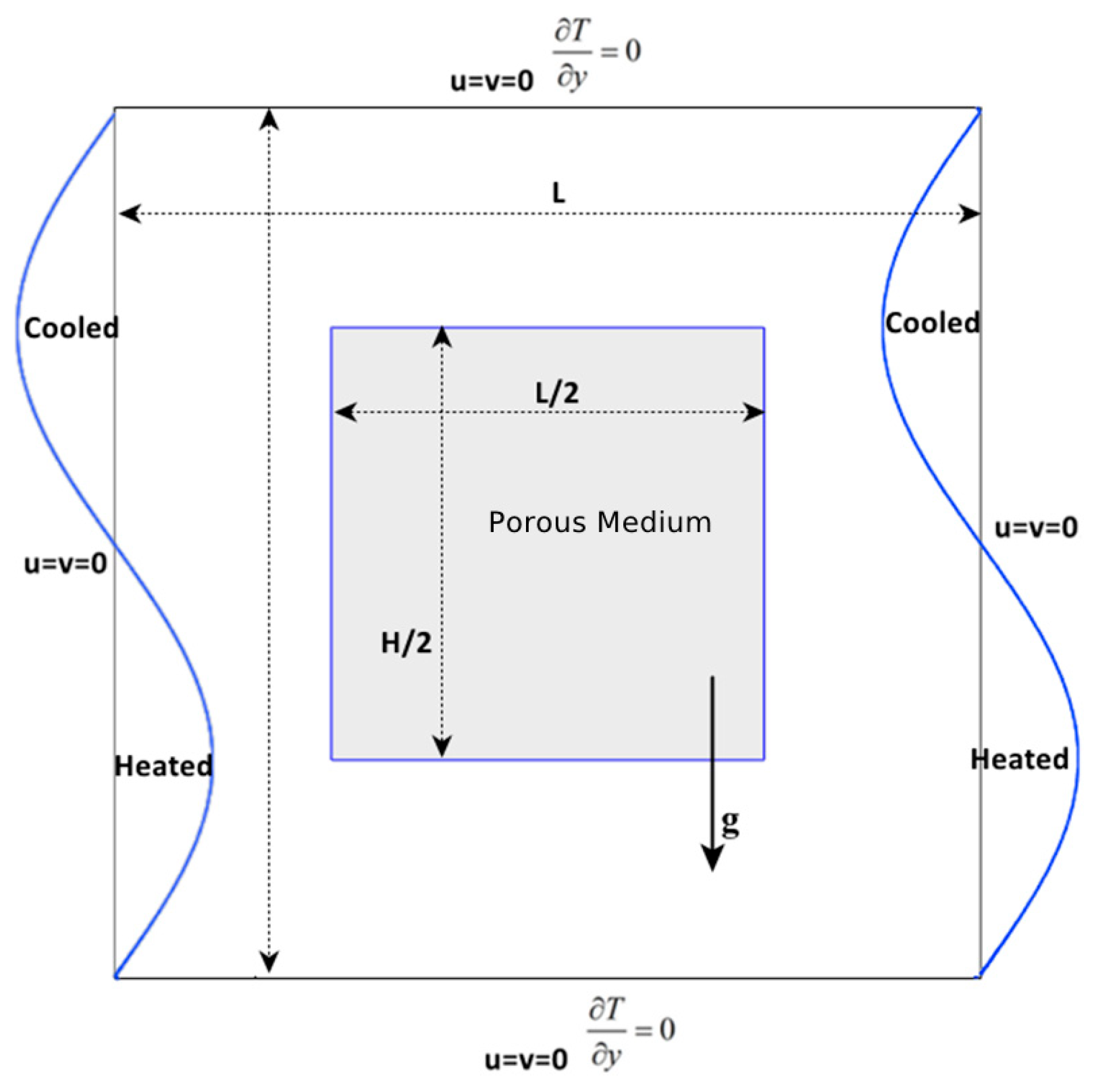
In this study, the method of finite elements (FEM) is used to conduct a detailed analysis of laminar, steady-state, 2D flow situations. The simulation is specifically designed to investigate the behavior of smooth, incompressible airflow within a square cavity. This approach allows for a precise examination of the flow dynamics within the cavity, providing insights into how the air moves and interacts with the boundaries. Figure 1 illustrates the configuration of the square cavity, highlighting its dimensions and the flow pattern under investigation.
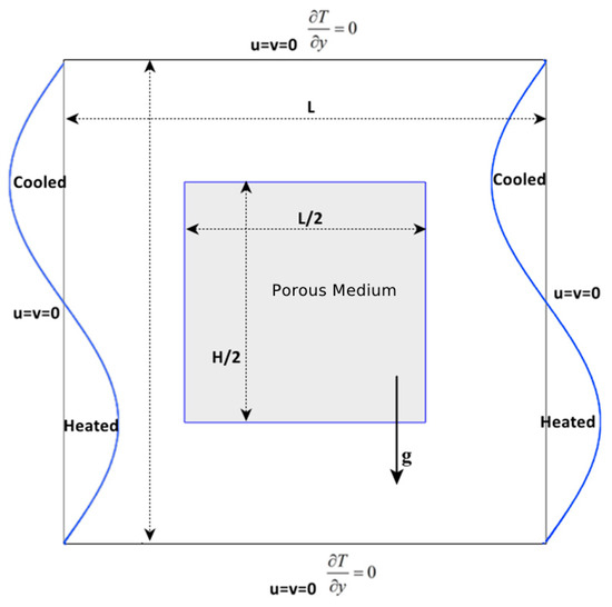
Figure 1.
Physical layout and coordinates.
The cavity under investigation is designed with solid walls encompassing a central square region, which is uniformly filled with a porous medium saturated with fluid. This configuration provides a controlled environment to study the interaction between the fluid and the porous structure.
To simulate the thermal conditions, null Neumann boundary conditions are applied to the horizontal walls, indicating that there is no heat flux across these surfaces. In contrast, the vertical walls experience sinusoidal heating, introducing a periodic temperature variation along their height.
This study is based on the following assumptions:
- -
- Fluid and porous medium properties are assumed constant.
- -
- In the momentum equations, both viscous drag and inertia are considered negligible.
- -
- Thus, it is valid to use the Boussinesq approximation.
- -
- Laws based on the Darcy–Brinkman law are applicable.
2.2. Mathematical Formulation
2.2.1. Porous Domain
In their dimensional form, the porous layer’s governing equations are as:
The continuity:
The equation that characterizes the momentum along the x-axis is as follows:
The equation that characterizes momentum along the y-axis:
The equation of energy:
2.2.2. Fluid Domain
The fluid layer’s dimensional governing equations are:
The continuity:
The equation that characterizes the momentum along the x-axis is as follows:
The equation that characterizes momentum along the y-axis:
The equation of energy:
The following nondimensional parameters were established:
Therefore, the conservation equation, when translated into a dimensionless form, can be similarly articulated for the porous layer.
The continuity:
The equation that characterizes the momentum along the x-axis is as follows:
The equation that characterizes momentum along the y-axis:
The equation of energy:
For fluid layer:
The continuity:
The equation that characterizes the momentum along the x-axis is as follows:
The equation that characterizes momentum along the y-axis:
The equation of energy:
2.3. Specifications of Boundary Conditions
Figure 2 provides a detailed representation of the boundary conditions applied to the system. At the outer limits, all solid surfaces maintained zero velocity, with a zero normal pressure gradient. The temperature gradient was zero at the adiabatic boundaries. A sinusoidal temperature profile was applied to the vertical sides, resulting in heating at the lower section and cooling at the upper section.
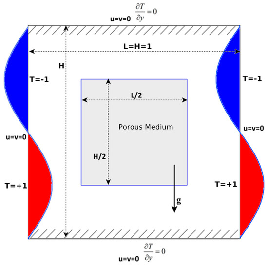
Figure 2.
Diagram showing boundary conditions.
Therefore, in all cavity sides, we apply non-slip conditions:
At and ; :
where, Th represents the amplitude of the dimensionless temperature variation.
At and ; :
2.4. Numerical Method and Validation
2.4.1. Numerical Methodology
Numerical solutions for the governing equations were obtained by applying the FEM within the COMSOL Multiphysics software (version 5.0). To achieve this, the equations were discretized using a scheme that incorporated quadratic shape functions for representing the velocity fields, ensuring a higher degree of accuracy in capturing the variations in velocity across the domain. In contrast, linear shape functions were used for the pressure fields, consistent with the P2 + P1 discretization approach commonly employed in fluid dynamics simulations. The temperature fields were discretized using quadrature Lagrange elements. To enhance convergence, the boundary fluxes were smoothed using an appropriate algorithm.
2.4.2. Mesh Characteristics
An unstructured mesh of triangular elements was used to discretize the computational domain, with quadratic elements introduced at the boundaries. The final mesh configuration comprised approximately 114,468 elements. The assessment of mesh quality revealed the following parameters: the lowest element quality was 0.116, the average element quality was 0.9011, and the element area ratio stood at 0.001092.
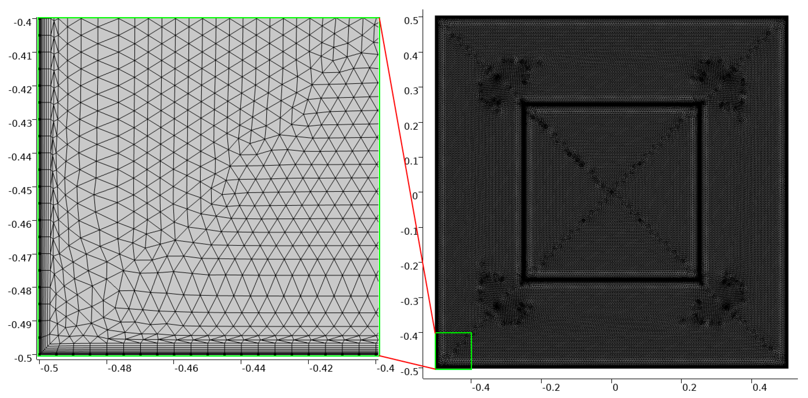
A comprehensive grid refinement study was conducted to ensure grid independence. Regions expected to exhibit significant gradients, particularly adjacent to the walls and the porous medium interface, as illustrated in Figure 3, underwent localized mesh refinement. The best mesh resolution was found when further refinement no longer significantly changed the computational results.
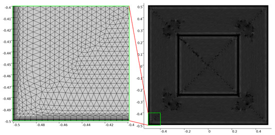
Figure 3.
Triangular and quadratic meshes.
2.4.3. Convergence Criteria
The numerical solution was obtained using a fully coupled stationary solver combined with a direct linear solver system. The nonlinear aspects of the problem were handled using an automatic Newton method, with a minimum damping factor of 10−6 to ensure stability and convergence. Typical simulations converged within approximately 140 iterations. The robustness of the solution was confirmed by the final nonlinear solver error values, which consistently remained below the threshold of 10−7, indicating a high degree of numerical accuracy.
2.4.4. Computational Resources
Simulations used the following high-performance workstation:
- -
- Processor: AMD Ryzen 9 3900X 12-Core, 3.80 GHz.
- -
- Memory: 64 GB RAM.
- -
- Operating system: Windows 10 Pro.
Under these hardware configurations, the average computational time for a representative simulation was approximately 60 min.
2.4.5. Validation
The effectiveness of this approach was validated through the analysis of buoyancy-driven flow within a square enclosure with vertically heated sides. The results showed a close alignment with the observations reported by Wan et al. [32], particularly in relation to the local Nu number on the heated side. This alignment is illustrated in Figure 4, demonstrating that the methodology accurately reflects the thermal dynamics of the system.
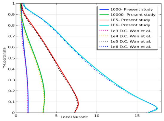
Figure 4.
Variation in local Nu numbers on the heated wall across various Ra numbers [32].
Furthermore, our comparison with the average Nu number findings of Wan et al. [32], De Vahl Davis [33], and Bilgen & Yedder [34] demonstrates a strong agreement, further reinforcing the validity and reliability of our study, as detailed in Table 1.

Table 1.
Nu number averages across different Ra numbers in a cavity subjected to differential heating.
Additionally, Table 2 presents a comprehensive comparison of average Nu numbers at various positions for different Ra numbers, further validating the robustness of our study. This comparison demonstrates consistent agreement with the results documented by De Vahl Davis [33].
Table 2.
Comparative Nu numbers for square cavity with differential heating.
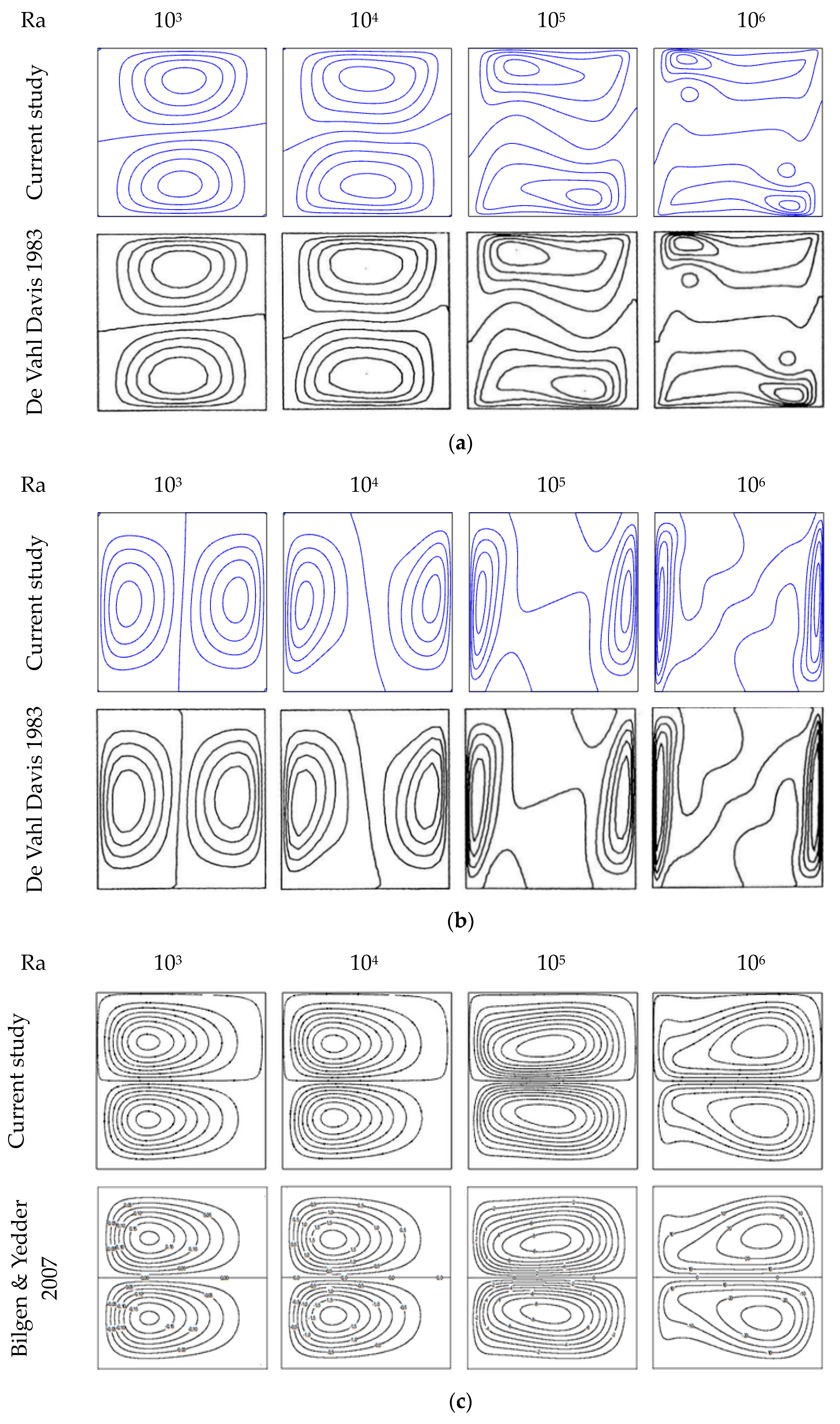
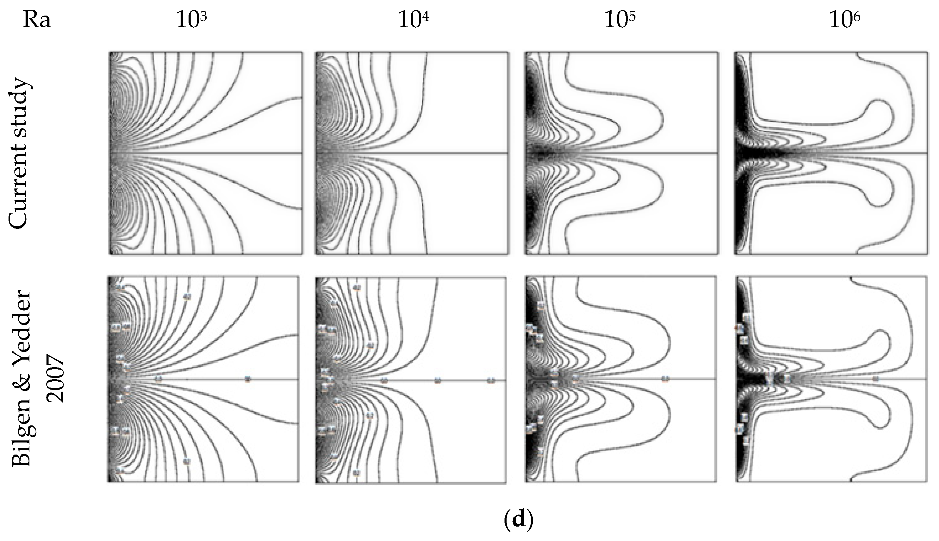
In another comparison, we evaluated the contours of horizontal and vertical velocities from our study, covering Ra numbers from 103 to 106, against those reported by De Vahl Davis [33]. Our analysis revealed that the contours provided the most accurate representation, as shown in Figure 5a,b, further reinforcing the reliability of our findings.
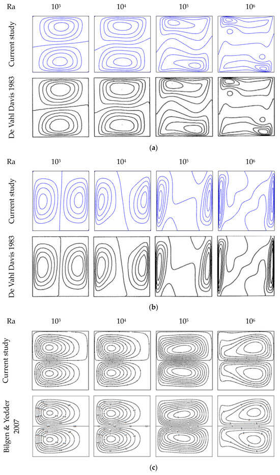
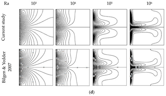
Figure 5.
Comparison of hydrothermal fields in our simulation with literature [33,34] across various Ra numbers. (a) Horizontal velocity (u) contours; (b) Vertical velocity () contours; (c) Flow patterns resulting from a sinusoidal temperature profile on a left vertical wall; (d) Temperature fields from a left vertical wall with a sinusoidal temperature profile.
To further validate our results, we conducted an additional assessment, which demonstrated strong agreement with the work of Bilgen & Yedder [34]. As illustrated in Figure 5c,d, they applied a sinusoidal temperature to the left vertical side of a rectangular enclosure, heating the lower section while cooling the upper section, with the other sides insulated.
3. Results and Discussions
This part provides and examines the outcomes of a non-dimensional FEM simulation investigating natural air circulation within a 2D cavity under steady-state laminar conditions. The simulation focuses on the behavior of incompressible air flow within a cavity characterized by equal height (H = 1) and length (L = 1), with an isotropic porous medium incorporated at its center. This setup allows for a detailed examination of temperature distribution, air circulation patterns, and the impact of sinusoidal heating on flow dynamics. The study covers a range of Ra numbers from 102 to 105 and Da numbers from 10−1 to 10−4.
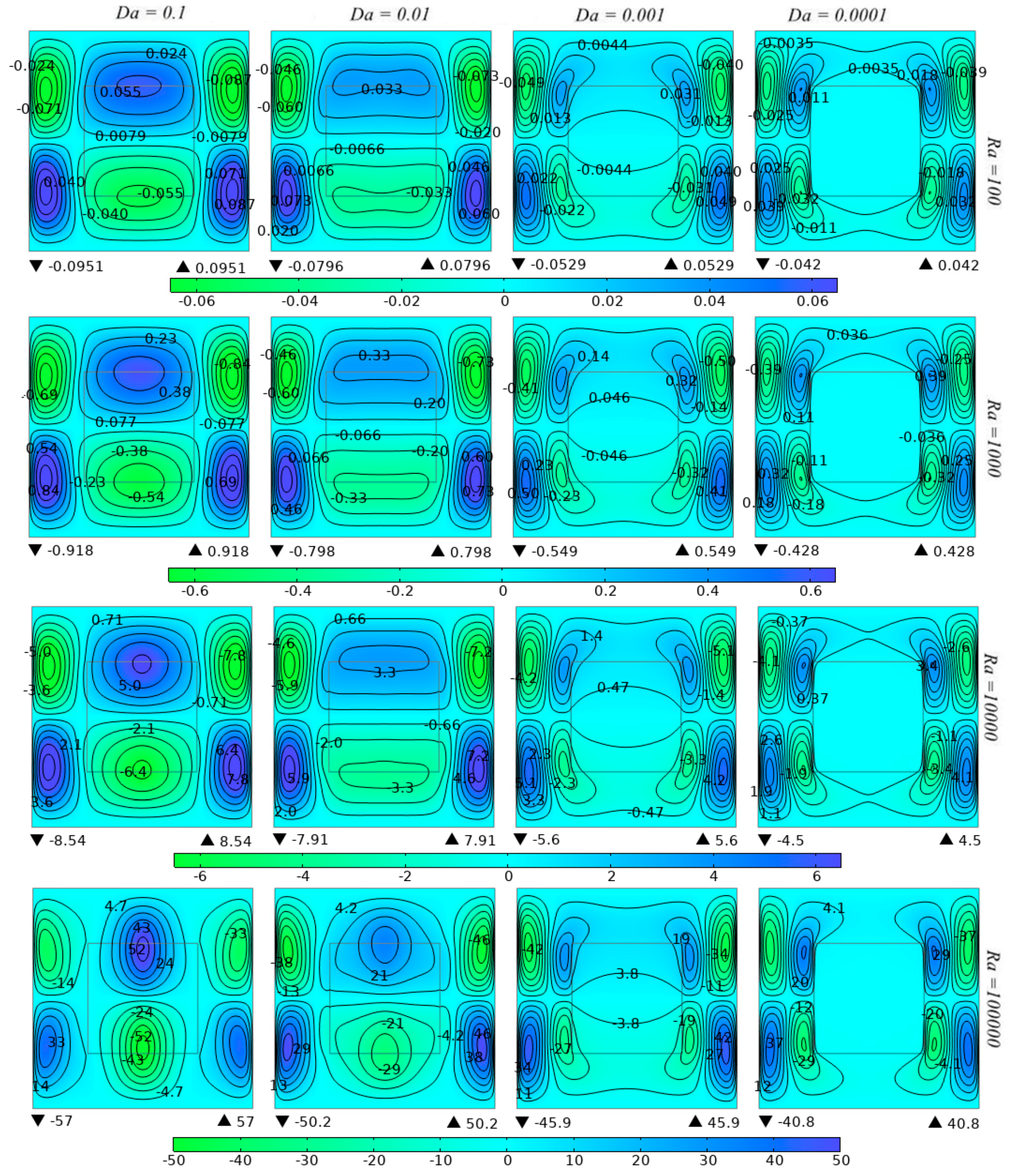
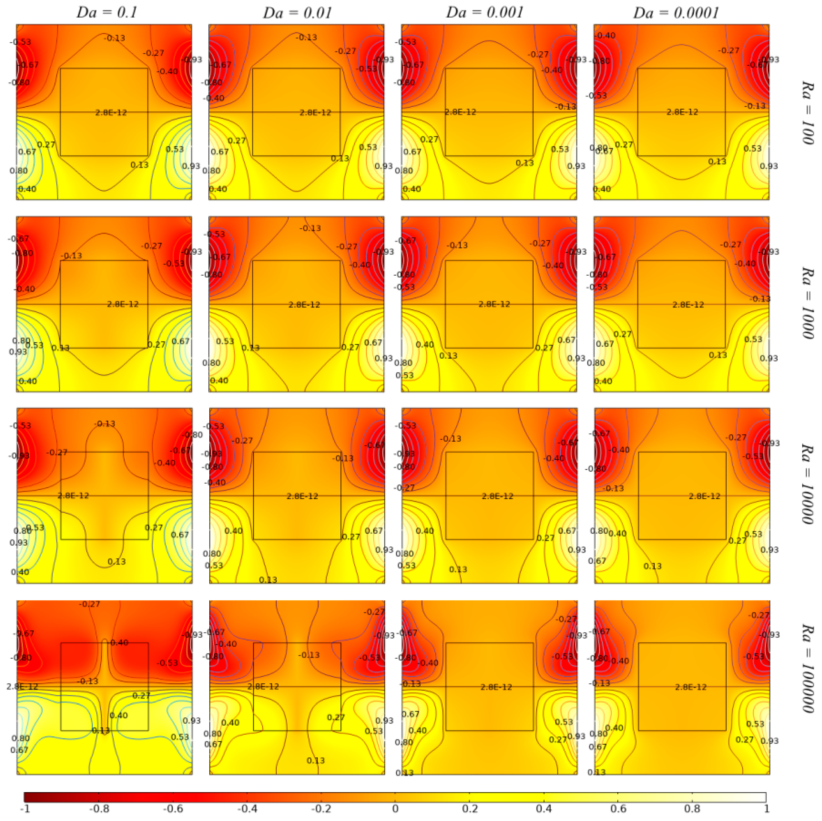
The analysis, depicted in Figure 6, Figure 7, Figure 8, Figure 9, Figure 10, Figure 11 and Figure 12, reveals consistent flow behavior across the studied range of Da and Ra numbers. Notably, when Da values are high and Ra values are low, particularly in the upper left portion of the series, the flow behavior demonstrates a high degree of uniformity and limited circulation.
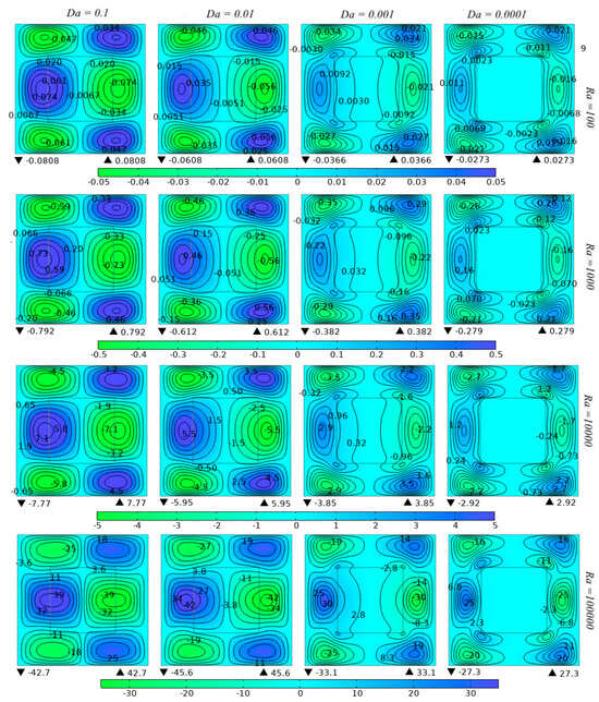
Figure 6.
X-velocity patterns across varying Da and Ra numbers within the studied cavity.
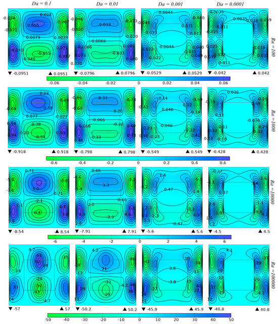
Figure 7.
Visualization of y-velocity fields within the studied cavity across a range of and numbers.
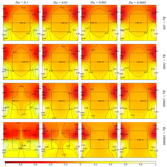
Figure 8.
Surface temperature and isotherms within the studied cavity across a range of and numbers.
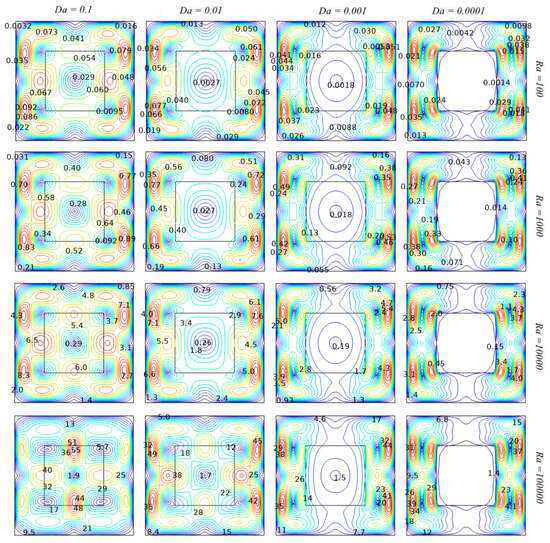
Figure 9.
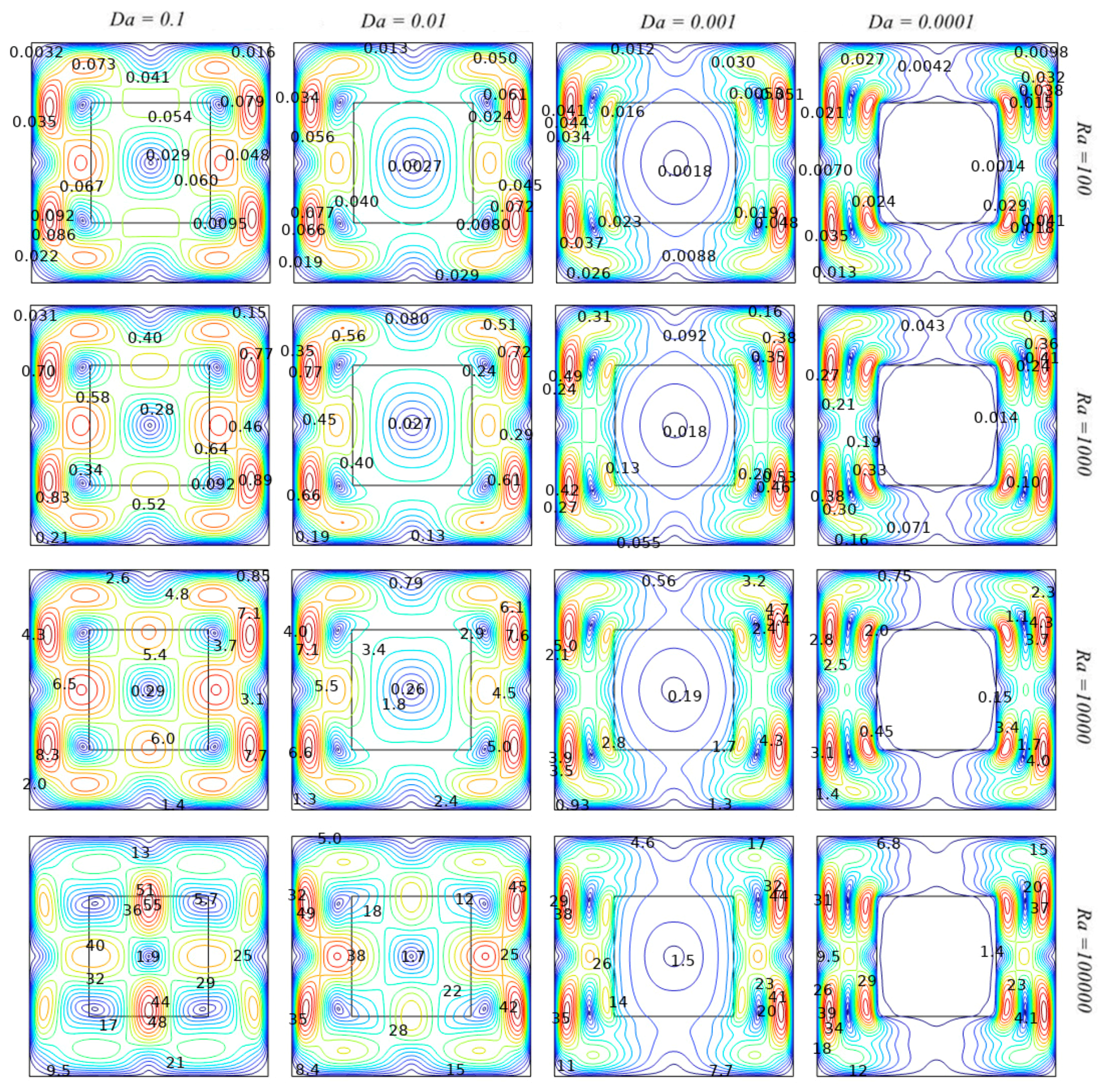
Velocity magnitude fields within the studied cavity across a range of Da and Ra numbers.
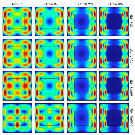
Figure 10.
Representation of surface velocity magnitude fields within the studied cavity across a range of and numbers.
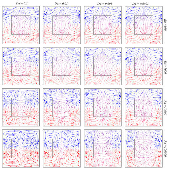
Figure 11.
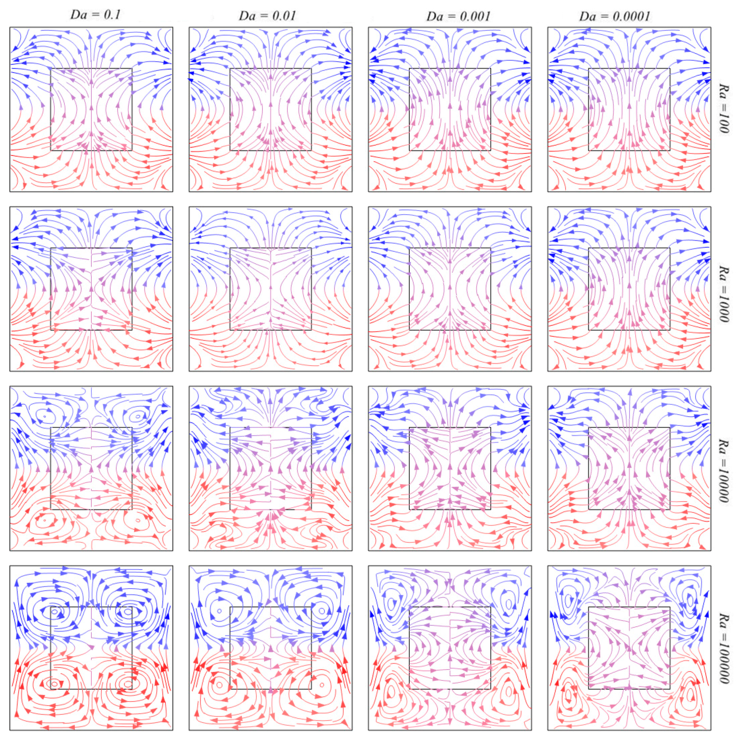
Visualization of heatline patterns within the studied cavity across a range of Da and Ra numbers.
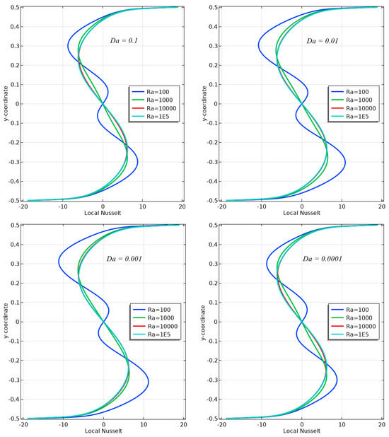
Figure 12.
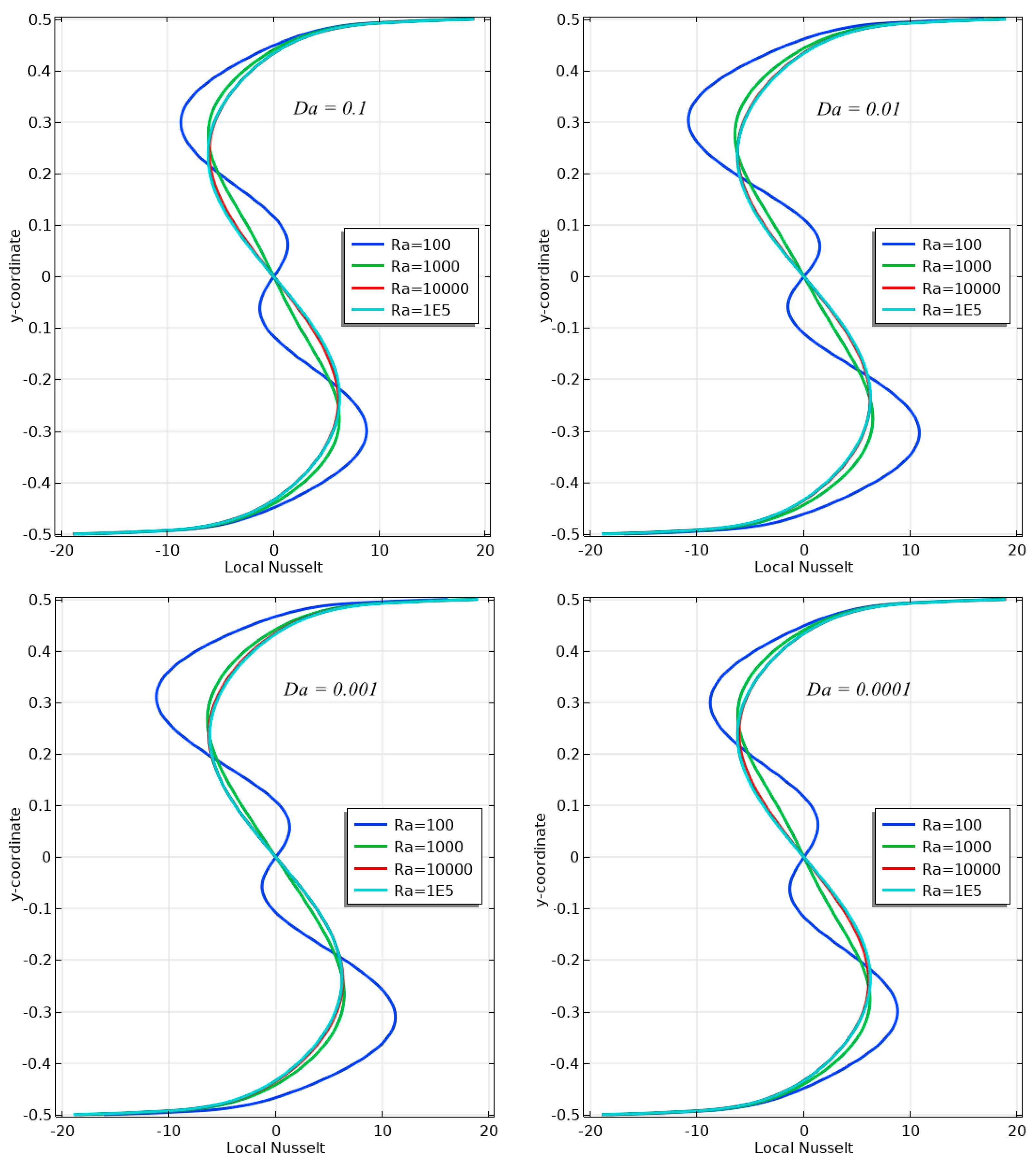
Local Nu number trends along the left boundary for diverse Ra and Da values.
This observation indicates that the fluid moves readily through the porous material due to its high permeability, even with weak buoyant forces driving the flow. However, in the lower right segment, where Da values are lowest and Ra values are highest, situation changes. The velocity contours become tightly packed and more complex, reflecting the presence of vigorous convection currents. These currents are driven by strong buoyant forces that effectively overcome the resistance of the porous medium, as illustrated in Figure 6 and Figure 7. As the Ra number increases, convection becomes increasingly dynamic, characterized by more active convection cells and enhanced circulation. Conversely, lower Da values heighten the medium’s resistance to flow, which is evident from the deviation of contour lines and the reduction in velocity magnitudes. The central porous block is instrumental in influencing the FF behavior, leading to the distortion and splitting of convection cells as they interact with the porous region.
The cavity’s temperature distribution is significantly impacted by the Da number, indicating the porous medium’s permeability, as shown in Figure 8. Higher Da values lead to a more uniform temperature profile, whereas lower Da values result in steeper temperature gradients and reduced uniformity. With increasing Ra number, buoyancy-driven convection increasingly dominates, transitioning the transfer mechanism of heat from being primarily conduction-dominated to convection-dominated. The central porous medium adds complexity to the flow and temperature fields, altering both convection patterns and temperature distribution. The combination of adiabatic horizontal walls and sinusoidal vertical heating creates a distinctive isotherm pattern that is highly sensitive to variations in Da and Ra.
The Da number significantly affects cavity flow: higher Da values ease flow, while lower Da values increase resistance. The central porous block plays a critical role in influencing both the magnitude and direction of the flow, which is pivotal in the overall convection process (see Figure 9 and Figure 10). The interaction between the adiabatic boundaries and sinusoidal heating generates diverse flow regimes, which are crucial for optimizing heat exchangers, enhancing thermal insulation, or cooling electronic devices. The presence of the porous block alters flow patterns and heat distribution, underscoring its importance in fluid movement and HT within the system.
Figure 11 illustrates the heat flow patterns in a square cavity under varying Da and Ra numbers. Red lines represent heat moving away from heated regions, while blue lines depict heat moving towards cooled regions. The central square denotes the porous medium, which significantly influences the heat flow.
At a high Da number (0.1), the heatlines are more dispersed, indicating that the porous medium facilitates HT with minimal resistance. Conversely, at a low Da number (0.0001), the heatlines become concentrated around the heated and cooled walls, reflecting greater resistance to HT.
With a low Ra number (102), the streamlines are relatively simple, showing weak natural convection with limited interaction between hot and cold regions. In contrast, at a high Ra number (105), the patterns become more complex, with closely packed red and blue lines, indicating strong convection and vigorous HT.
Across all scenarios, the centrally placed porous block disrupts the natural heat flow, altering both the direction and density of the heatlines around it. Acting as a barrier, it interrupts straightforward convection patterns, leading to a more complex heat transfer mechanism.
The adiabatic assumption for the horizontal walls ensures that no HT occurs through these boundaries. The sinusoidal temperature variation along the vertical walls, with heating at the bottom and cooling at the top, serves as the main catalyst for convection, as indicated by the initiation and termination points of the heatlines along these boundaries.
Figure 12 depicts HT along the left wall of the porous cavity using local Nu numbers with different Da and Ra numbers. At higher Ra values (105), convective HT is markedly improved, as evidenced by the elevated Nu numbers, indicating stronger buoyancy forces at these Ra values. With decreasing Da from 10−1 to 10−4, the Nu profiles become steeper near the y-axis, suggesting that the medium’s permeability has a notable impact on convective HT.
At the lowest Ra value (102), HT predominantly occurs through conduction, as indicated by the low and consistent Nu numbers. As Ra increases, convective HT improves across all Da values, with the Nu number reaching its peak near the center of the cavity. This peak marks the region where convective HT is most intense near the wall.
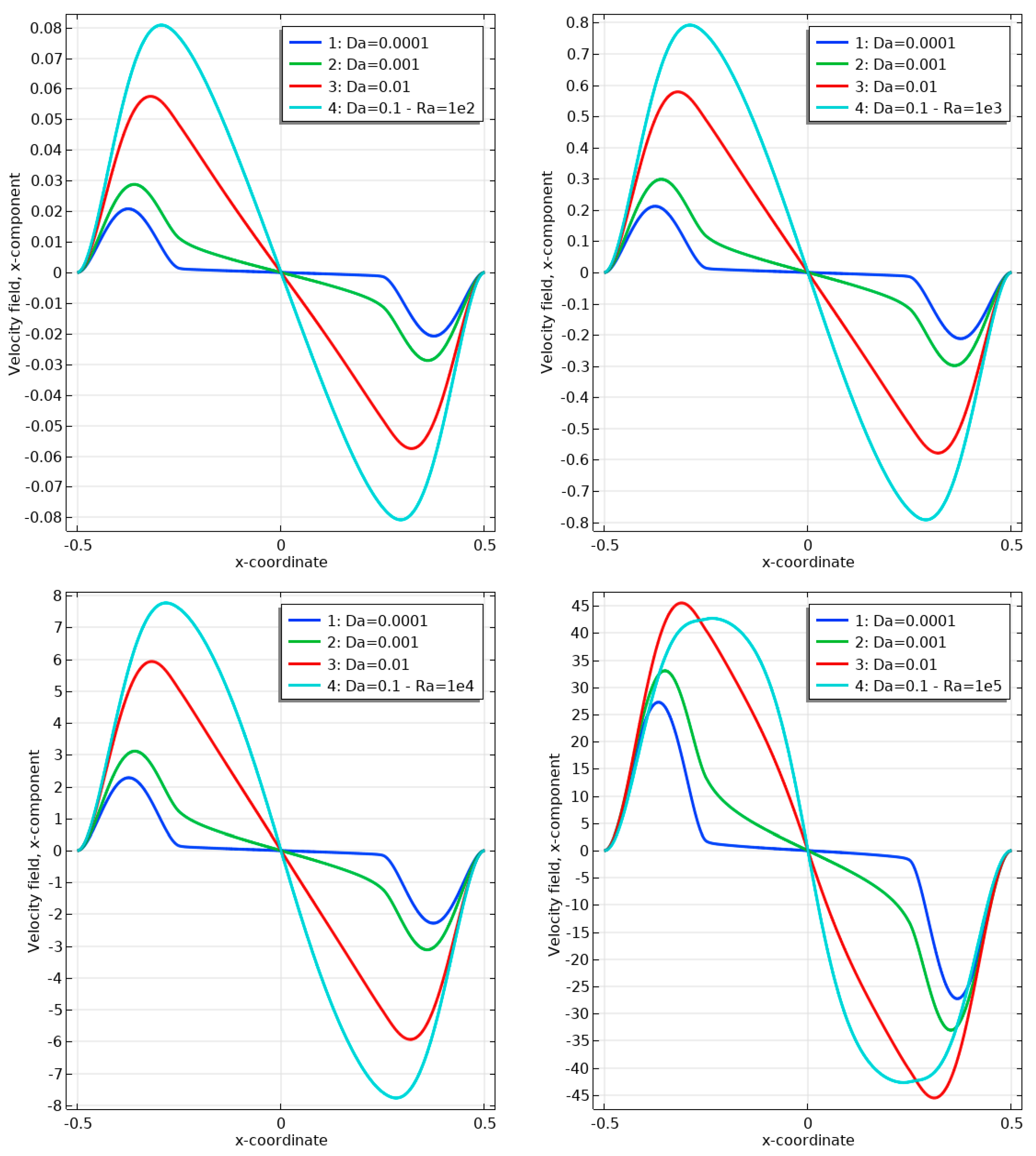
Figure 13 presents line graphs depicting the x-component velocity distribution along the central horizontal line in the studied cavity, for Da and Ra numbers varying from 10−1 to 10−4 and 102 to 105, respectively. As Ra increases, indicating stronger buoyancy-driven flow, the x-component velocity also rises, reflecting more vigorous convection. The highest velocities occur at Ra = 105, signifying significant convective activity. At lower Ra values, the flow is weaker, suggesting that conduction dominates over convection.
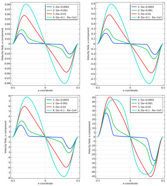
Figure 13.
X-component velocity along the middle horizontal line for different Ra and Da numbers.
The Da number also influences the flow: at Da = 0.1, the flow is more uniform with less resistance from the porous medium. In contrast, at Da = 0.0001, the velocity profiles exhibit higher peaks and steeper gradients, indicating greater resistance and a more pronounced impact of the porous medium. This comparison shows how fluid flow is sensitive to changes in medium permeability and thermal driving forces.
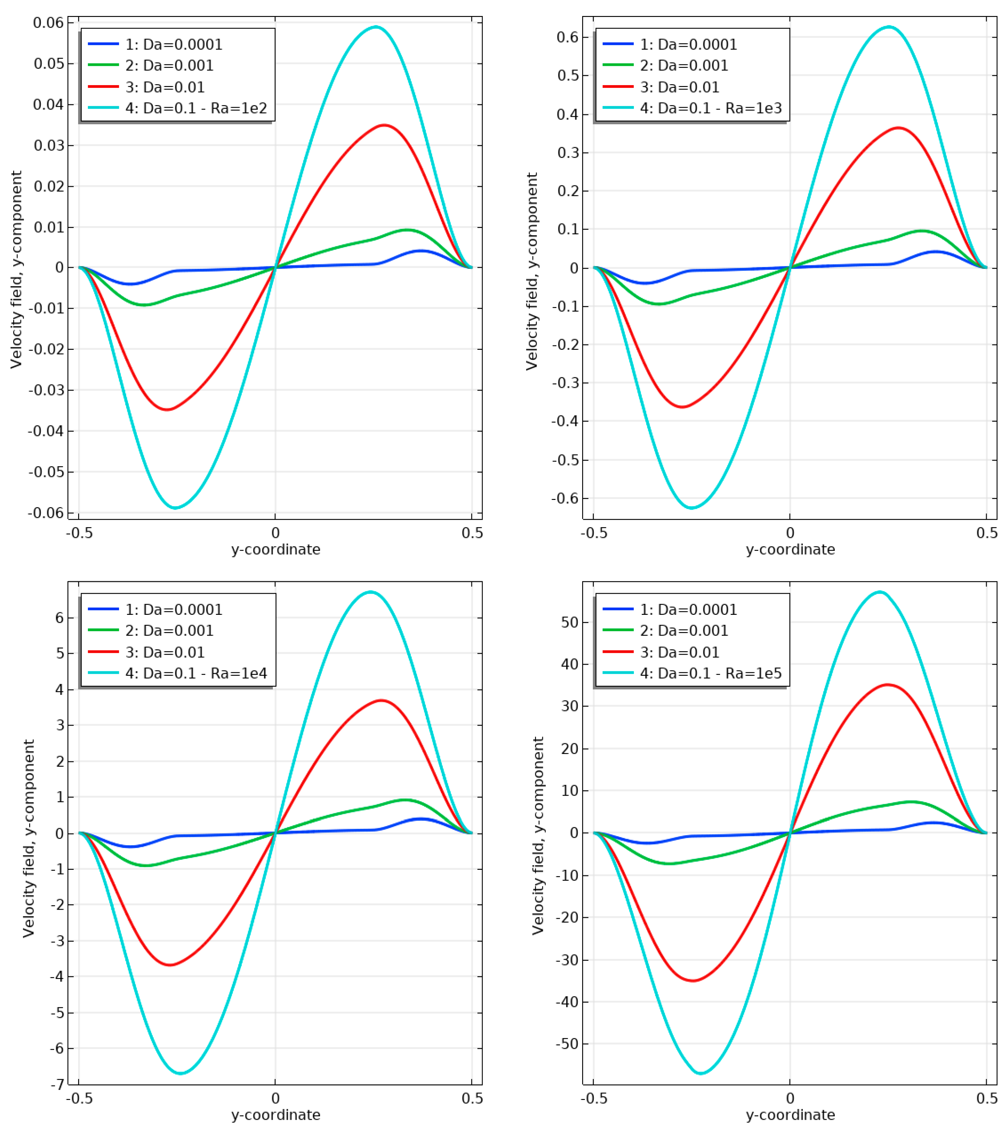
Figure 14 illustrates the y-component velocity profile through the vertical midline of the studied cavity for various Da and Ra numbers. At higher Ra values, the y-component of velocity increases, indicating stronger fluid movement driven by enhanced buoyancy forces. The highest velocities are observed at Ra = 105, reflecting intense convective activity. As Da numbers decrease, the fluid encounters greater resistance due to the reduced permeability of the medium. The variations in velocity profiles with different Da numbers, particularly at higher Ra, highlight the complex relationship between fluid motion and the properties of the medium.
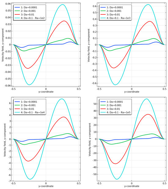
Figure 14.
Visualization of the y-component velocity along the mid-vertical line within the cavity.
4. Conclusions
This study utilized finite element analysis to explore laminar natural convection within a differentially heated porous cavity using the Darcy–Brinkman model. The research focused on a square cavity containing an isotropic porous medium at its center, analyzing the effects of varying Da and Ra numbers. It was found that at low Da values, the porous medium significantly hindered FF, leading to higher velocity gradients and localized HT, while higher Da values facilitated more uniform flow and heat distribution.
Furthermore, the findings of this study demonstrate that, as the Ra number increased from 102 to 105, there was a marked enhancement in local convective HT, transitioning from a conduction-dominated regime to a convection-dominated one, emphasizing the role of buoyancy forces. Consequently, the study observed that higher Ra values led to increased Nu numbers, with the maximum Nu consistently located around the central vertical section of the cavity. Complex flow structures, characterized by multiple convection cells and enhanced circulation, emerged at higher Ra and lower Da numbers, significantly influenced by the central porous block.
In addition to the flow behavior, the temperature distribution analysis revealed that lower Da values resulted in steeper temperature gradients and less uniform profiles. The sinusoidal heating on the vertical walls, along with adiabatic horizontal walls, created distinct isotherm patterns sensitive to changes in Da and Ra. These findings collectively contribute to optimizing thermal management systems in various industries, such as geothermal energy, electronic cooling, and thermal insulation design, enhancing our understanding of HT in porous media.
While this study provides valuable insights, it is important to acknowledge the limitations of the employed 2D model. 3D effects, such as flow variations in the spanwise direction, are not captured in the current analysis and might influence the overall HT behavior, particularly at higher Ra numbers where more complex flow structures could emerge. Moreover, the applicability of Squire’s theorem, which simplifies stability analysis in parallel flows, is limited in this context due to the non-parallel nature of the flow caused by the buoyancy-driven convection and the presence of the porous medium. Therefore, future investigations employing 3D simulations could provide a more comprehensive understanding of these phenomena. Nevertheless, the present 2D study offers a valuable foundation for understanding the fundamental mechanisms at play and provides practical insights relevant to various thermal management applications.
Author Contributions
Conceptualization, B.F., N.K., S.A., Y.M., B.M.A. and L.K.; methodology, B.F., N.K., S.A., Y.M., B.M.A. and L.K.; software, B.F., N.K., S.A., Y.M., B.M.A. and L.K.; validation, B.F., N.K., S.A., Y.M., B.M.A. and L.K.; investigation, B.F., N.K., S.A., Y.M., B.M.A. and L.K.; resources, B.F., N.K., S.A., Y.M., B.M.A. and L.K.; writing—original draft preparation, B.F., N.K., S.A., Y.M., B.M.A. and L.K.; writing—review and editing, B.F., N.K., S.A., Y.M., B.M.A. and L.K.; All authors have read and agreed to the published version of the manuscript.
Funding
This work was supported and funded by the Deanship of Research and Graduate Studies at King Khalid University through Large Research Project, under grant number RGP2/352/45.
Data Availability Statement
The data presented in this study are available upon reasonable request from the corresponding author.
Acknowledgments
The authors extend their appreciation to the Deanship of Research and Graduate Studies at King Khalid University for funding this work through Large Research Project, under grant number RGP2/352/45.
Conflicts of Interest
The authors declare no conflicts of interest.
Nomenclature
| CP | Specific heatat constant pressure (J·kg−1·K −1) |
| Da | Darcy number (Da = κ/L2) |
| g | Gravitational field (m·s−2) |
| H | Cavity height (m) |
| k | Thermal conductivity (W·m−1·K−1) |
| L | Cavity length (m) |
| Nu | Nusselt number |
| p | Pressure (N·m−2) |
| Pr | Prandtl number |
| Ra | Rayleigh number |
| T | Temperature (K) |
| u | Velocity component along x-direction (m·s−1) |
| U | Dimensionless velocity component along x-direction |
| v | Velocity component along y-direction (m·s−1) |
| V | Dimensionless velocity component along y-direction |
| x, y | Cartesian coordinates (m) |
| X, Y | Dimensionless Cartesian coordinates |
| Greek Symbols | |
| β | Thermal expansion coefficient (K−1) |
| Porosity of the porous layer | |
| ν | Kinematic viscosity (m2·s−1) |
| θ | Dimensionless temperature |
| ρ | Density (kg·m−3) |
| κ | Permeability of porous medium (m2) |
| μ | Dynamic viscosity (Pa·s) |
| α | Thermal diffusivity (m2·s−1) |
| Subscripts | |
| eff | Effective |
| f | Fluid |
| h | Hot |
| s | Solid |
| w | Wall |
References
- Xu, J.; Wei, H.; Bao, H. Physics-informed neural networks for studying heat transfer in porous media. Int. J. Heat Mass Transf. 2023, 217, 124671. [Google Scholar] [CrossRef]
- Kaviany, M. Principles of Heat Transfer in Porous Media; Springer Science & Business Media: Berlin, Germany, 2012. [Google Scholar] [CrossRef]
- Tien, C.L.; Vafai, K. Convective and radiative heat transfer in porous media. Adv. Appl. Mech. 1989, 27, 225–281. [Google Scholar] [CrossRef]
- Vafai, K.; Tien, C.L. Boundary and inertia effects on flow and heat transfer in porous media. Int. J. Heat Mass Transf. 1981, 24, 195–203. [Google Scholar] [CrossRef]
- Mekroussi, S.; Kherris, S.; Mebarki, B.; Benchatti, A. Mixed convection in complicated cavity with non-uniform heating on both sidewalls. Int. J. Heat Technol. 2017, 35, 1023–1033. [Google Scholar] [CrossRef]
- Walker, K.L.; Homsy, G.M. Convection in a porous cavity. J. Fluid Mech. 1978, 87, 449–474. [Google Scholar] [CrossRef]
- Kumar, A.; Pramanik, S.; Mishra, M. COMSOL Multiphysics® Modeling in Darcian and Non-Darcian Porous Media. In Proceedings of the 2016 COMSOL Conference, Bangalore, India, 20–21 October 2016; pp. 20–21. [Google Scholar]
- Baytas, A.C.; Pop, I. Free convection in a square porous cavity using a thermal nonequilibrium model. Int. J. Therm. Sci. 2002, 41, 861–870. [Google Scholar] [CrossRef]
- Saidi, L.; Mekroussi, S.; Kherris, S.; Zebbar, D.; Mébarki, B. A numerical investigation of the free flow in a square porous cavity with non-uniform heating on the lower wall. Eng. Technol. Appl. Sci. Res. 2022, 12, 7982–7987. [Google Scholar] [CrossRef]
- Saeid, N.H. Natural convection in porous cavity with sinusoidal bottom wall temperature variation. Int. Commun. Heat Mass Transf. 2005, 32, 454–463. [Google Scholar] [CrossRef]
- Muyungi, W. Effects of Navier Slip and Skin Friction on Nanofluid Flow in a Porous Pipe. Ph.D. Thesis, NM-AIST, Arusha, Tanzania, 2022. [Google Scholar] [CrossRef]
- Menni, Y.; Chamkha, A.J.; Kaid, N.; Ameur, H.; Bensafi, M.; Sahel, D.; Lorenzini, G. Advances of heat transfer in porous media—A review. Spec. Top. Rev. Porous Media Int. J. 2020, 11, 1–18. [Google Scholar] [CrossRef]
- Huang, C.W.; Srikanth, V.; Kuznetsov, A.V. The evolution of turbulent micro-vortices and their effect on convection heat transfer in porous media. J. Fluid Mech. 2022, 942, A16. [Google Scholar] [CrossRef]
- Nabwey, H.A.; Armaghani, T.; Azizimehr, B.; Rashad, A.M.; Chamkha, A.J. A comprehensive review of nanofluid heat transfer in porous media. Nanomaterials 2023, 13, 937. [Google Scholar] [CrossRef] [PubMed]
- Douha, M.; Draoui, B.; Kaid, N.; Ameur, H.; Belkacem, A.; Mohamed, E.; Merabti, A.; Aissani, H. Study of laminar naturel convection in partially porous cavity in the presence of nanofluids. J. Adv. Res. Fluid Mech. Therm. Sci. 2021, 79, 91–110. [Google Scholar] [CrossRef]
- Li, B.; Xu, H.; Song, Y.J.; Zhang, H.L.; Wang, W.W.; Zhao, F.Y. Heat and moisture transports in a slot ventilated enclosure packed with discrete porous media: Mixing convection instability, oscillation and resonance. Int. J. Therm. Sci. 2023, 194, 108603. [Google Scholar] [CrossRef]
- Liu, J.; Yu, P.; Li, Y.; Wan, C.; Du, D. Numerical simulation on convective heat transfer characteristics in porous media based on the digital rock technology. Int. J. Heat Mass Transf. 2022, 196, 123323. [Google Scholar] [CrossRef]
- Lauriat, G.; Ghafir, R. Forced convective heat transfer in porous media. In Handbook of Porous Media; Dekker: New York, NY, USA, 2000; pp. 201–204. [Google Scholar] [CrossRef]
- Chu, X.; Yang, G.; Pandey, S.; Weigand, B. Direct numerical simulation of convective heat transfer in porous media. Int. J. Heat Mass Transf. 2019, 133, 11–20. [Google Scholar] [CrossRef]
- Shenoy, A.V. Non-Newtonian fluid heat transfer in porous media. Adv. Heat Transf. 1994, 24, 101–190. [Google Scholar] [CrossRef]
- Zhu, X.; Pan, D.; Gao, Y.; Guo, Y.; Guan, Y.; Ma, H. Heat transfer enhancement in a regenerative cooling channel using porous media. Chem. Eng. Process. Process Intensif. 2023, 183, 109234. [Google Scholar] [CrossRef]
- Younus, Y.M.; Raheem, H.M.; Al-Hajjar, A.M. Novel approach for modeling a full-sized air-cooled heat exchanger using porous media and iterative processes. Results Eng. 2023, 20, 101459. [Google Scholar] [CrossRef]
- Bazneshin, M.N.; Borji, M.; Gholami, R. Numerical Investigation of phase transition in different latent heat storage systems in the presence of natural convection and porous media. Case Stud. Therm. Eng. 2023, 50, 103450. [Google Scholar] [CrossRef]
- Grosan, T.; Patrulescu, F.O.; Pop, I. Natural convection in a differentially heated cavity filled with a Brinkman bidisperse porous medium. Int. J. Numer. Methods Heat Fluid Flow 2023, 33, 3309–3326. [Google Scholar] [CrossRef]
- Javed, S.; Saha, S. Estimation of comprehensive thermal performance for conjugate natural convection inside a dome-shaped porous chamber holding a solid cylinder. Results Eng. 2023, 17, 100896. [Google Scholar] [CrossRef]
- Shruti, B.; Alam, M.M.; Parkash, A.; Dhinakaran, S. Darcy number influence on natural convection around porous cylinders in an enclosure using Darcy-Brinkman-Forchheimer model: LBM study. Case Stud. Therm. Eng. 2023, 45, 102907. [Google Scholar] [CrossRef]
- Aslam, M.A.; Yao, H.; Al Mesfer, M.K.; Irshad, K.; Chuhan, I.S.; Danish, M.; Hassan, A.M.; Shahzad, H.; Eldin, S.M. Finite element modeling of dual convection in a Y shaped porous cavity containing viscus fluid. Front. Phys. 2023, 11, 1207462. [Google Scholar] [CrossRef]
- Abderrahmane, A.; Manoongam, A.; Alizadeh, A.A.; Younis, O.; Zekri, H.; Isa, S.S.P.M.; Baghaei, S.; Jamshed, W.; Guedri, K. Investigation of the free convection of nanofluid flow in a wavy porous enclosure subjected to a magnetic field using the Galerkin finite element method. J. Magn. Magn. Mater. 2023, 569, 170446. [Google Scholar] [CrossRef]
- Al-Waaly, A.A.; Tumpa, S.A.; Nag, P.; Paul, A.R.; Saha, G.; Saha, S.C. Entropy generation associated with natural convection within a triangular porous cavity containing equidistant cold domains. Front. Energy Res. 2024, 12, 1422256. [Google Scholar] [CrossRef]
- Issakhov, A.; Sabyrkulova, A.; Abylkassymova, A. Study of coupled natural convection in a two-dimensional square cavity with a partition with solid and porosity properties. Int. Commun. Heat Mass Transf. 2024, 155, 107539. [Google Scholar] [CrossRef]
- Charreh, D.; Islam, S.U.; Talib, S.; Saleem, M.; Abbas, M.A.; Ahmad, S. Numerical investigation of entropy generation and Magnetohydronamic natural convection in a porous square cavity with four embedded cylinders. Heliyon 2024, 10, 33897. [Google Scholar] [CrossRef]
- Wan, D.C.; Patnaik, B.S.V.; Wei, G.W. A new benchmark quality solution for the buoyancy-driven cavity by discrete singular convolution. Numer. Heat Transf. Part B Fundam. 2010, 40, 199–228. [Google Scholar] [CrossRef]
- de Vahl Davis, G. Natural convection of air in a square cavity: A bench mark numerical solution. Int. J. Numer. Methods Fluids 1983, 3, 249–264. [Google Scholar] [CrossRef]
- Bilgen, E.; Yedder, R.B. Natural convection in enclosure with heating and cooling by sinusoidal temperature profiles on one side. Int. J. Heat Mass Transf. 2007, 50, 139–150. [Google Scholar] [CrossRef]
- Fenni, M.; Guellal, M.; Hamimid, S. Influence of porosity properties on natural convection heat transfer in porous square cavity. Phys. Fluids 2024, 36, 056108. [Google Scholar] [CrossRef]
- Karpenko, M. Aircraft hydraulic drive energy losses and operation delay associated with the pipeline and fitting connections. Aviation 2024, 28, 1–8. [Google Scholar] [CrossRef]


Disclaimer/Publisher’s Note: The statements, opinions and data contained in all publications are solely those of the individual author(s) and contributor(s) and not of MDPI and/or the editor(s). MDPI and/or the editor(s) disclaim responsibility for any injury to people or property resulting from any ideas, methods, instructions or products referred to in the content. |
© 2024 by the authors. Licensee MDPI, Basel, Switzerland. This article is an open access article distributed under the terms and conditions of the Creative Commons Attribution (CC BY) license (https://creativecommons.org/licenses/by/4.0/).