Article

Study on the Equivalent Density Tool and Depressurisation Mechanism of Suction-Type Depressurisation Cycle

1
CNOOC Research Institute Ltd., Beijing 100028, China
2
State Key Laboratory of Petroleum Resource and Prospecting, China University of Petroleum, Beijing 102249, China
3
College of Petroleum Engineering, Xi’an Shiyou University, Xi’an 710065, China
4
Engineering Research Center of Development & Management for Western Low to Extra-Low Permeability Oilfield, Xi’an Shiyou University, Xi’an 710065, China
*
Author to whom correspondence should be addressed.
Processes 2024, 12(9), 2017; https://doi.org/10.3390/pr12092017
Submission received: 4 July 2024 / Revised: 7 September 2024 / Accepted: 16 September 2024 / Published: 19 September 2024
(This article belongs to the Section Energy Systems)

Abstract

:
In order to further regulate equivalent circulating density (ECD), a novel downhole apparatus for reducing circulating pressure in high-temperature and high-pressure wells, the suction-type ECD reduction tool, was devised. The utilisation of this tool enables the bottomhole pressure of the equivalent circulating density to be attained in close proximity to its hydrostatic pressure, thereby facilitating the attainment of deeper drilling depths. The tool is composed primarily of a screw motor, scroll blades, annular seals, universal joints, and drilling columns. The tool operates by utilising the suction effect and hydraulic energy extracted from the circulating fluid by the screw motor, which is then converted into mechanical energy to create suction and enhance the flow energy of the drilling fluid within the annulus at the bottom of the well, thereby reducing the equivalent circulating density. Furthermore, based on ANSYS-FLUENT analysis simulations, the alteration of pressure drop characteristics in response to varying drilling fluid densities, displacements, and tool sizes was modelled. The simulation results demonstrate that the pressure drop effect is 1.0 MPa when the drilling fluid density is 1.2 g/cm3, 1.7 MPa when the drilling fluid density is 1.5 g/cm3, and 1.9 MPa when the drilling fluid density is 1.8 g/cm3. A pressure drop of approximately 2.3 MPa was observed when the drilling fluid density was 2.0 g/cm3. The maximum pressure drop is achievable with a flow rate ranging from 1500 to 2500 L/min. A maximum pressure drop of 2.3 MPa is observed when the flow rate is within the range of 1500 to 2500 L/min. Two distinct viscosity values (0.02 and 0.06 kg/(m·s)) were employed to assess the impact of viscosity on pressure drop characteristics in a suction-type ECD tool. The results demonstrated that the pressure drop remained largely unaltered, indicating that viscosity had minimal influence on this parameter. The flow rate emerged as the primary factor affecting pressure drop, with viscosity exerting a relatively minor effect.

1. Introduction

The advancement of drilling technology has been a continuous process, with notable improvements observed in the drilling and research of deep oil and gas reservoirs. There has been a surge in research activities pertaining to high-temperature and high-pressure drilling, both domestically and internationally. However, it is notable that the majority of research principles and theories related to high-temperature and high-pressure wells have their origins in the extension of land drilling comparisons. The deepening of offshore exploration and development has led to an increased prevalence of challenging drilling operations in high-temperature and high-pressure environments with narrow pressure windows. This has emerged as a significant obstacle impeding the safe and efficient drilling of offshore oilfields. Ultra-high temperature and high-pressure narrow density window drilling presents a significant challenge due to the high density of the drilling fluid and the high circulating rate, which narrows the operating window during the drilling cycle. This, in turn, increases the difficulty of ECD control and gives rise to other problems. The conventional downhole apparatus designed for the reduction in circulating pressure, including the jet hydraulic circulating pressure reduction tool, pulse jet pressure reduction tool, vortex hydraulic pressure reduction tool, and cyclone hydraulic circulating pressure reduction tool, have been observed to lack a discernible impact on pressure reduction and are unable to adequately address the issue of ECD reduction.
In 2008, Zheng Feng hui et al. [1] employed the developed jet hydraulic pressure reduction simulation tool and its corresponding test rig to conduct an empirical investigation into a jet hydraulic pressure reduction method that effectively reduces the bottomhole pressure under conventional drilling methods. In 2012, Yuan Guang yu et al. [2] provided a comprehensive account of the structural characteristics, pressure reduction effect and research applications of the method. The status of jet pump pressure reduction tools, including the annular jet pump, the jet pressure reduction short section, and the jet pump bit, is as follows. In 2013, Zhu Haiyan et al. [3] proposed a novel annular jet pump structure based on the principle of jet hydraulic pressure reduction technology. In 2016, Dokhani V. et al. [4] developed a simulator for calculating wellbore temperatures and pressures under circulating and static conditions and established a mathematical model for heat transfer in offshore inclined well profiles, which was subsequently validated. In 2016, Erge O. et al. [5] presented a numerical model to accurately estimate the circulating friction pressure loss with and without inner tube rotation. The numerical model was validated using ANSYS software (v15.0). In 2019, Abdelgawad et al. [6] developed an artificial neural network (ANN) and an adaptive neuro-fuzzy inference system (ANFIS). The established ANN and ANFIS models calculate ECD. In 2019, Huang Yi et al. [7] derived a risk evaluation model by applying the generalised stress and strength interference reliability theory based on the probability distributions of formation pressure and ECD. The resulting calculation coincided with the actual risk of occurrence in the field. In 2021, Chen Yuwei et al. [8] employed a transient rock chip transport model to simulate the transient transport process of rock chips in a wellbore and to analyse the effect of rock chips on ECD in conjunction with data from actual wells drilled. In 2021, Huang Wei et al. [9] conducted a study on the calculation method of ECD in the wellbore of a horizontal well in Changning shale gas wells. Additionally, they explored the methods of calculating the equivalent static density and the equivalent circulating density of drilling fluids under different temperature and pressure conditions. In 2022, Duan Hongzhi et al. [10] conducted high-temperature and high-pressure density experiments on oil-based drilling fluids commonly used in the Xinjiang oilfield with the objective of establishing an accurate model for calculating ECD at the bottom of a well. In 2022, Foued B. et al. [11] proposed a new model to predict ECD in both straight and inclined wells, which predicted the rock chip concentration and equivalent circulating density in both types of well. In 2022, Gao Yongde et al. [12] developed a borehole temperature field model for subsea pressurisation in response to the difficult problem of predicting ECD in deepwater high-temperature, high-pressure wells. In 2022, Wei Xiaoqi et al. [13] discussed high-temperature and high-pressure well calibration and control technology. In light of the current situation, the development trend was considered, and the various key points of the ECD calibration and control technology were summarised. In 2023, Li Wentuo et al. [14] employed coupled drilling wells to predict ECD in straight and inclined wells, thereby improving the accuracy of ECD calculation. In 2023, Okonkwo et al. [15] optimised the ECD model using four error indexes: correlation coefficient (R2), mean squared error (MSE), root mean squared error (RMSE), and average absolute percentage error (AAPE). These indexes demonstrated efficacy in optimising the ECD model. The optimised ECD model has been demonstrated to have high prediction accuracy. In 2023, Mohammed et al. [16] developed two new models, ECDeffc.m and MWeffc.m, which have been shown to improve the computational accuracy of ECD. In 2003, Hao Xining et al. [17] examined the impact of key parameters, including wellbore temperature, pressure and rock cutting concentration. A model for calculating the wellbore ECD of double-layer continuous tubing with double-gradient drilling was developed to analyse the influence of factors such as drilling fluid displacement and drilling fluid density on wellbore ECD. This provides an effective solution to address challenges such as the narrow pressure window for deepwater drilling and the propensity for leakage at shallow depths.
This paper presents the use of a novel pressure reduction tool, the suction-type ECD reduction tool, for the reduction in ECD size within the wellbore. Based on ANSYS-FLUENT analysis and simulation, the change in pressure reduction characteristics under different drilling fluid densities, displacements, and tool sizes is modelled. The simulation results demonstrate that the pressure drop effect reaches 2 MPa in the case of a high-density window and up to 2.3 MPa in the case of high-displacement working conditions. The viscosity has a negligible impact on the pressure drop effect and is primarily influenced by the flow rate under equal displacement. Furthermore, the experimental results from a North China oil field substantiate that the pressure reduction effect is in alignment with the field requirements.
In conclusion, the conventional pressure reduction apparatus is constrained in its capacity to reduce pressure, exhibiting minimal efficacy. This renders it unsuitable for addressing the challenges posed by high-temperature and high-pressure narrow pressure window drilling. In contrast, the novel suction-type ECD apparatus proposed in this paper has been validated. The numerical simulation and on-site verification demonstrate that the pressure reduction effect reaches 2 MPa, which effectively addresses the challenge of drilling narrow pressure windows in high-temperature and high-pressure environments. This approach offers a novel solution to the problem of narrow pressure windows in high-temperature and high-pressure drilling.

2. The Structure of the Suction-Type Falling ECD Tool

2.1. Tool Structure and Depressurisation Principle

Conventional pressure reduction is achieved by reducing the mud density; however, in the case of a narrow density window, this may cause complications such as well surges. Therefore, this paper presents a new type of ECD reduction tool, the suction-type ECD reduction tool, which is designed to address this issue. The tool is able to reduce the bottomhole equivalent circulating density without reducing the mud density, thus ensuring the safety of operation under the narrow density window.
The tool primarily employs the suction effect, whereby the screw pump extracts the hydraulic energy of the circulating fluid and converts it into mechanical energy, generating a suction force that increases the flow energy of the drilling fluid in the annulus at the bottom of the well and reduces the equivalent circulating density. The tool is composed primarily of a screw motor, screw vane, annulus seal, and drilling column. The components of the tool, depicted in Figure 1a–d, are the stator, screw vane, universal joint and rotor. The operational principle of the tool is as follows: the rotor, situated within the stator, is driven by the screw motor at the top to rotate the spiral blades. The universal joint connects the rotor and the spiral blades, ensuring that the blades rotate vertically and stably.
The apparatus is equipped with a screw motor situated at the apex of the structure. This motor is responsible for the conversion of hydraulic energy, which is generated by the circulating fluid, into mechanical energy. Subsequently, the screw mechanism drives the helical blades to rotate. The return fluid replenishes the energy and creates the requisite differential pressure within the annulus. Typically, the screw pump is matched to the vanes, thereby obviating the need for speed regulation. The lower section of the suction-type ECD-lowering tool is constituted by an annular seal that ensures the passage of all return fluids and rock chips through the pump. The annular seal is in continuous contact with the casing and is supported on bearings so that it remains stationary relative to the casing as the drill column rotates.

2.2. Parameters of Tools

While field applications have been conducted abroad, there have been fewer instances of such applications in China. Additionally, field applications have been carried out to demonstrate that there is a notable discrepancy in the extent of pressure reduction observed under varying drilling parameter conditions.
The suction-type ECD-lowering tool is a self-activating apparatus that is powered by circulating drilling fluid (Figure 2). The device is automatically activated when the drilling fluid is in circulation and deactivated when circulation ceases. The tool is capable of processing drilling fluids with densities up to 1.8 g/cm3. The current prototype has an outer diameter of 208.3 mm, an inner diameter of 46 mm, and is capable of being lowered into casing sizes ranging from 244.5 mm to 339.7 mm. Its length is approximately 9.15 m, with a connection length of 114.3 cm at the top and bottom. Additionally, it is capable of circulating fluid at a maximum rate of up to 2.27 L/min. The tool is capable of withstanding circulating rates of up to 2.270 L/min.

3. Numerical Simulation

This paper presents the results of numerical simulations conducted to analyse the pressure drop effect produced by the liquid-absorbing ECD tool under a range of conditions. A Solidworks physical model was constructed for the liquid-absorbing ECD tool, and the pressure drop characteristics under different parameters were simulated based on the ANSYS-FLUENT analysis.

3.1. The Simulation Pretreatment of the Liquid-Suction ECD Reduction Tool Model

3.1.1. Computation Module

The equivalent circulating density (ECD) of a drilling fluid can be defined as the sum of the equivalent static density of the drilling fluid and the pressure drop in the annulus caused by the flow of the drilling fluid. The equivalent circulating density expression for the field case is provided in Equation (1) below [18].
ρ ecd = ρ esd + Δ P 0.052 h
In the formula, ρ ecd is the cyclic equivalent density; ρ esd is the equivalent static density; and Δ P is the frictional pressure drop.
The control of downhole pressure is a fundamental aspect of high-temperature and high-pressure drilling. This process is influenced by several key factors, including the density and rheology of the drilling fluid. The equivalent circulating density (ECD) of the drilling fluid plays a crucial role in regulating the bottomhole pressure. The ECD expression for a field scenario is illustrated in Equation (2).
ECD = ρ ( 1 C a ) + ρ s C a + Δ p 0.00981 H
In the formula, ρ is the drilling fluid density; ρ s is the density of rock debris; C a is the concentration of annular cuttings; and Δ p is the annular pressure loss;
The following is a calculation formula for the annulus concentration calculation model (3):
C a = v a 3600 ( v c v a ) ( 1 d 0 2 d 2 )
In the formula, v a is the drilling speed; d 0 is the outer diameter of the drill pipe; d is the inner diameter of the wellbore; v c is the annular return velocity of drilling fluid; and v s is the settling velocity of rock debris.
The annular pressure loss calculation model: when the flow pattern is turbulent, the calculation formula of the pressure loss of the annular section is as follows (4):
Δ P = 2.04 f ρ v c 2 l d d 0
In the formula, Δ P is the annular pressure loss; l is the length of the drill pipe; d 0 is the outer diameter of the drill string; d is the inner diameter of the wellbore; v c is the annular return velocity of drilling fluid; f is the friction coefficient, dimensionless; and ρ is the density of the drilling fluid.

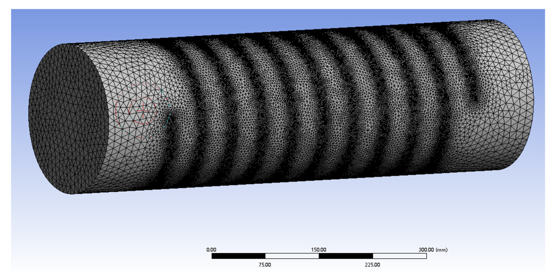
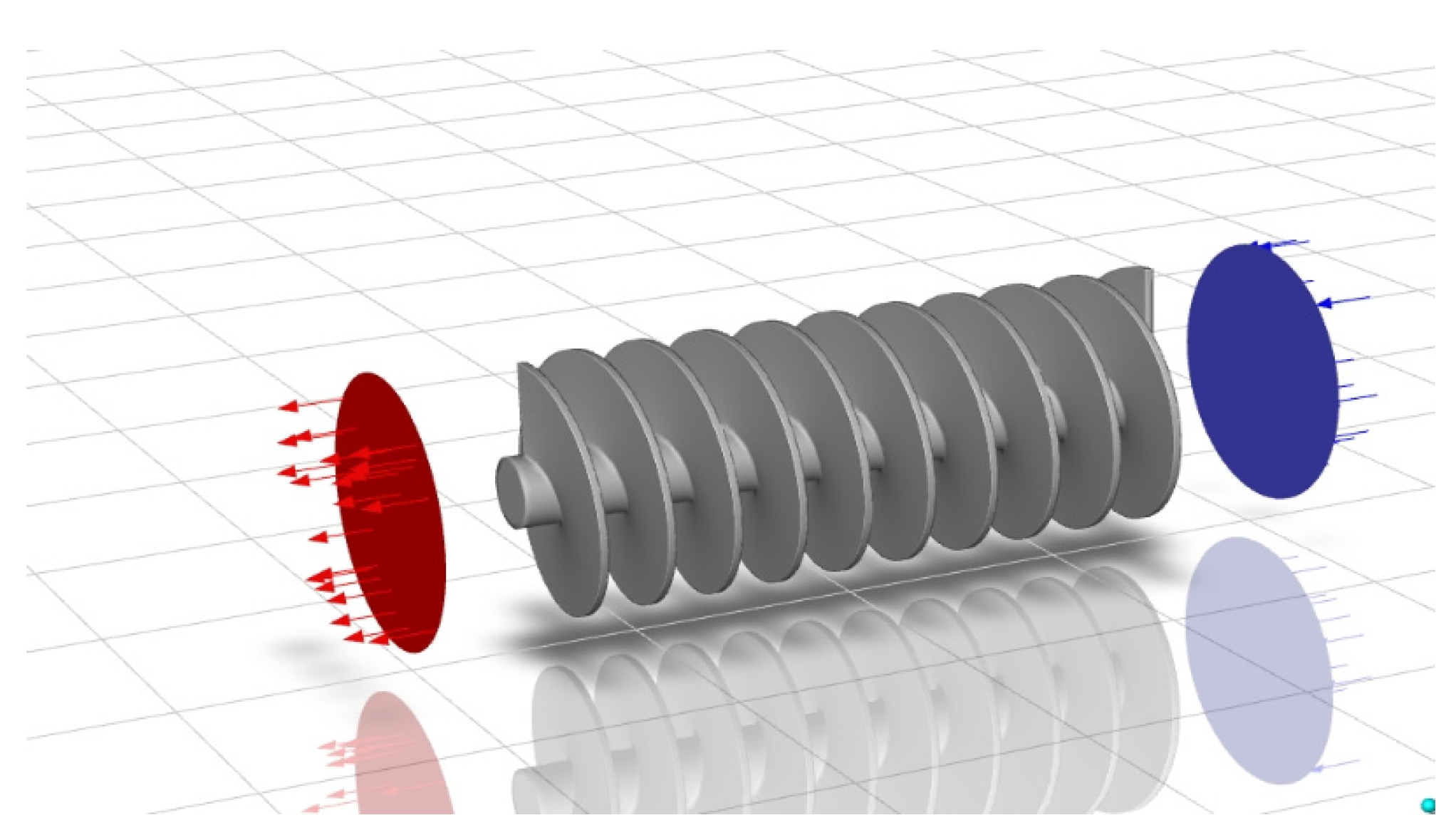
3.1.2. Meshing and Boundary Condition Setting

A physical model of the suction-liquid lowering ECD tool, constructed based on the Solidworks modelling tool 2022 (Dassault Systemes, Waltham, MA, USA), is used to establish a finite element analysis model of the tool by meshing the model. In order to ensure a certain degree of computational accuracy without an excessive computation time due to the large amount of computation, the key part of the tool prone to fatigue damage (the blade) is subjected to a more fine mesh division in order to enhance the accuracy of the calculation, as shown in Figure 3.
In the case of other parts of the structure that are relatively simple and more stable, a relatively coarse mesh is employed in order to enhance computational efficiency, as illustrated in Figure 4.
The boundary condition parameters of the tool are based on ANSYS-FLUENT and set to a well depth of 4275 m. The drilling fluid displacement is set to 1500–2500 L/min, the drilling fluid density is set to 1.2–2.8 g/cm3, and the inner diameter is set to 9–5/8 inches (244.5 mm), and the wellbore diameter is set to 190.5 mm, the starting and stopping drilling speed is set to 0.25 m/s, and the viscosity of the drilling fluid is set to 0.02–0.06. Set tool flow direction simulation (Figure 5).

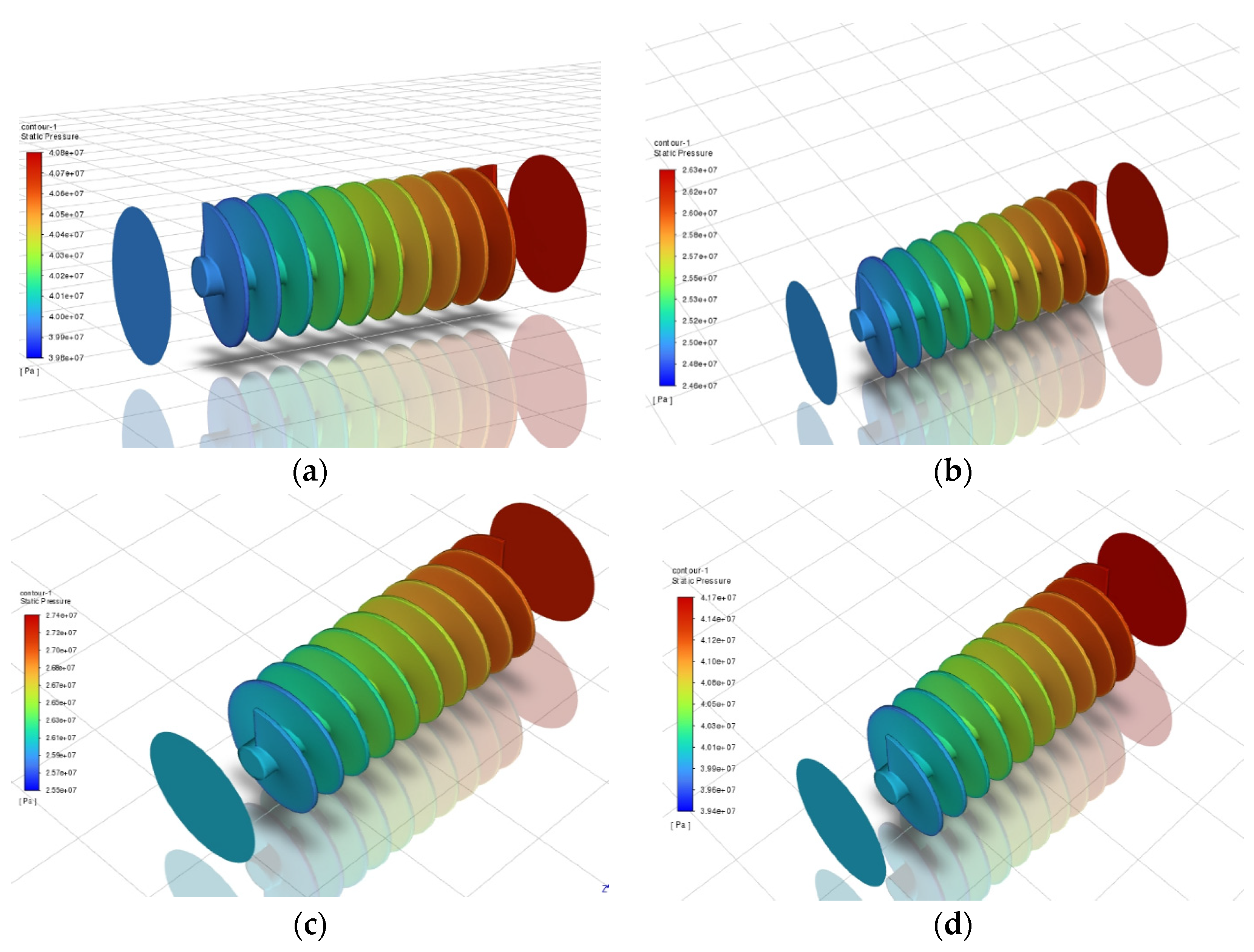
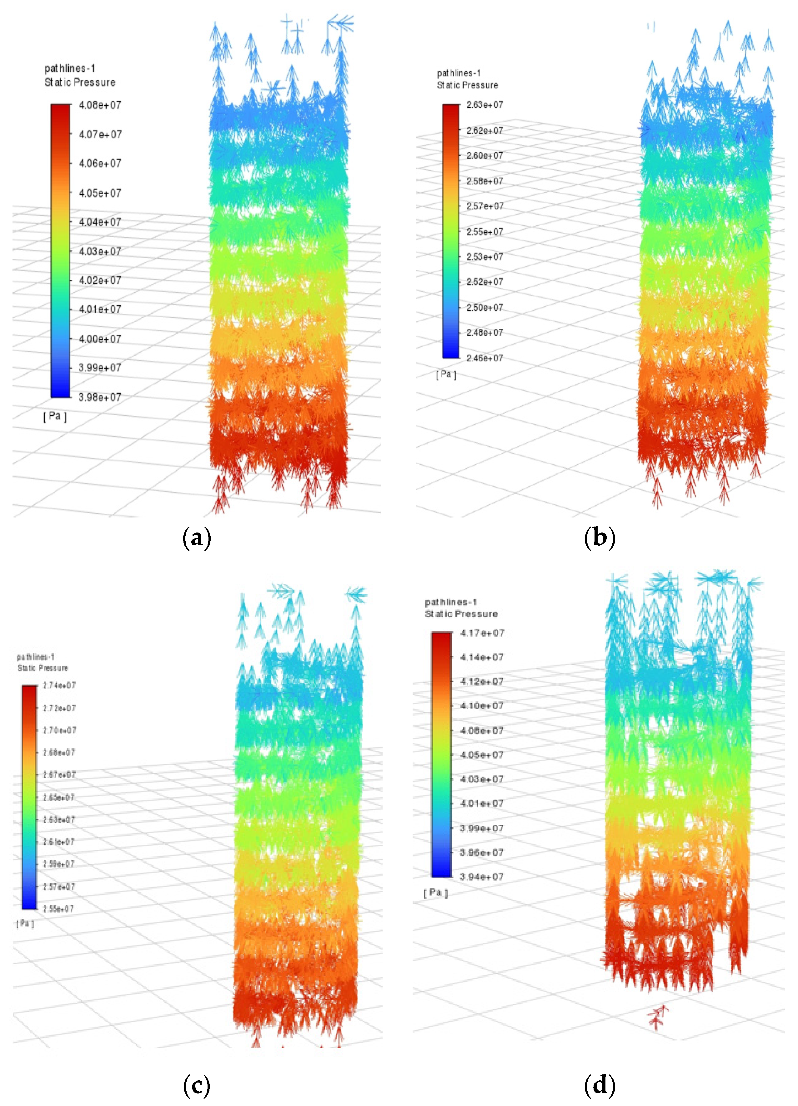
3.2. The Pressure Drop Distribution of the Liquid-Absorbing ECD-Reducing Tool When Drilling Fluid Flows with Different Densities

The pressure drop distribution characteristic maps (Figure 6) were simulated based on ANSYS-FLUENT for different parameters of drilling fluid density (1.2 g/cm3, 1.5 g/cm3, 1.8 g/cm3, 2.0 g/cm3) when flowing through the suction. The ECD-lowering tool of the type in question comprises four parameters of drilling fluid density, namely 1.2 g/cm3, 1.5 g/cm3, 1.8 g/cm3, and 2.0 g/cm3, which are represented by the symbols a, b, c, and d, respectively. The pressure drop distribution characteristic maps for these four parameters are presented in the figures labelled a, b, c, and d.
Figure 6 illustrates that when the drilling fluid density is 1.2 g/cm3, the pressure drop effect is minimal, reaching only 1 MPa. Conversely, when the drilling fluid density is 1.5 g/cm3, the pressure drop effect is more pronounced, with a pressure drop of approximately. A pressure drop of approximately 1.7 MPa was observed when the drilling fluid density was 1.8 g/cm3, while a pressure drop of approximately 1.9 MPa was noted when the drilling fluid density was 2.0 g/cm3. The simulation results demonstrate that an increase in drilling fluid density results in a notable fluctuation in pressure drop values, accompanied by a more pronounced pressure drop effect. However, it is essential to exercise caution and maintain reasonable control over drilling fluid density, as an excessive density may lead to elevated pressure within the wellbore, potentially increasing the risk of tool seal failure.
Figure 7 presents a simulation of four distinct fluid flow distribution characteristics, wherein the densities a, b, c, and d, which correspond to 1.2, 1.5, 1.8, and 2.0 g/cm3, respectively, offer a more intuitive visualisation. The characteristics of the distribution of the pressure drop of the fluid, as well as the direction of the flow, can be observed from the distribution of the fluid flow. It can be seen that, under different density conditions, there is a clear distribution of the pressure drop. However, it is notable that, as the density increases, so too does the pressure drop.

3.3. The Pressure Drop Distribution of the Liquid Absorption ECD Tool at Different Displacements

The pressure drop distribution characteristic plots (Figure 8) were simulated based on ANSYS-FLUENT for three different parameters of flow rate (1500 L/min, 2000 L/min, and 2500 L/min). When the suction-type ECD-lowering tool was in operation, the flow rates were, in order, 1500 L/min, 2000 L/min, and 2500 L/min for the a, b, and c flows, respectively.
A quantitative analysis of Figure 7 reveals that when the drilling fluid displacement is 1500 L/min, the pressure drop is 1.1 MPa; when the drilling fluid displacement is 2000 L/min, the pressure drop is approximately 1.7 MPa; and when the drilling fluid displacement is 2500 L/min, the pressure drop is approximately 2.3 MPa. It is evident that the pressure drop value exhibits considerable fluctuations in conjunction with an increase in drilling fluid displacement, with a particularly pronounced impact on the pressure drop. As the drilling fluid displacement increases, the pressure drop effect is enhanced. When the displacement is minimal, the tool pressure drop and shunt effects are not pronounced. Figure 9 illustrates the pressure drop distribution of the suction-type tool at varying drilling fluid discharges. The simulation outcomes demonstrate that the suction-type pressure drop tool exerts a more pronounced influence on local pressure drop.

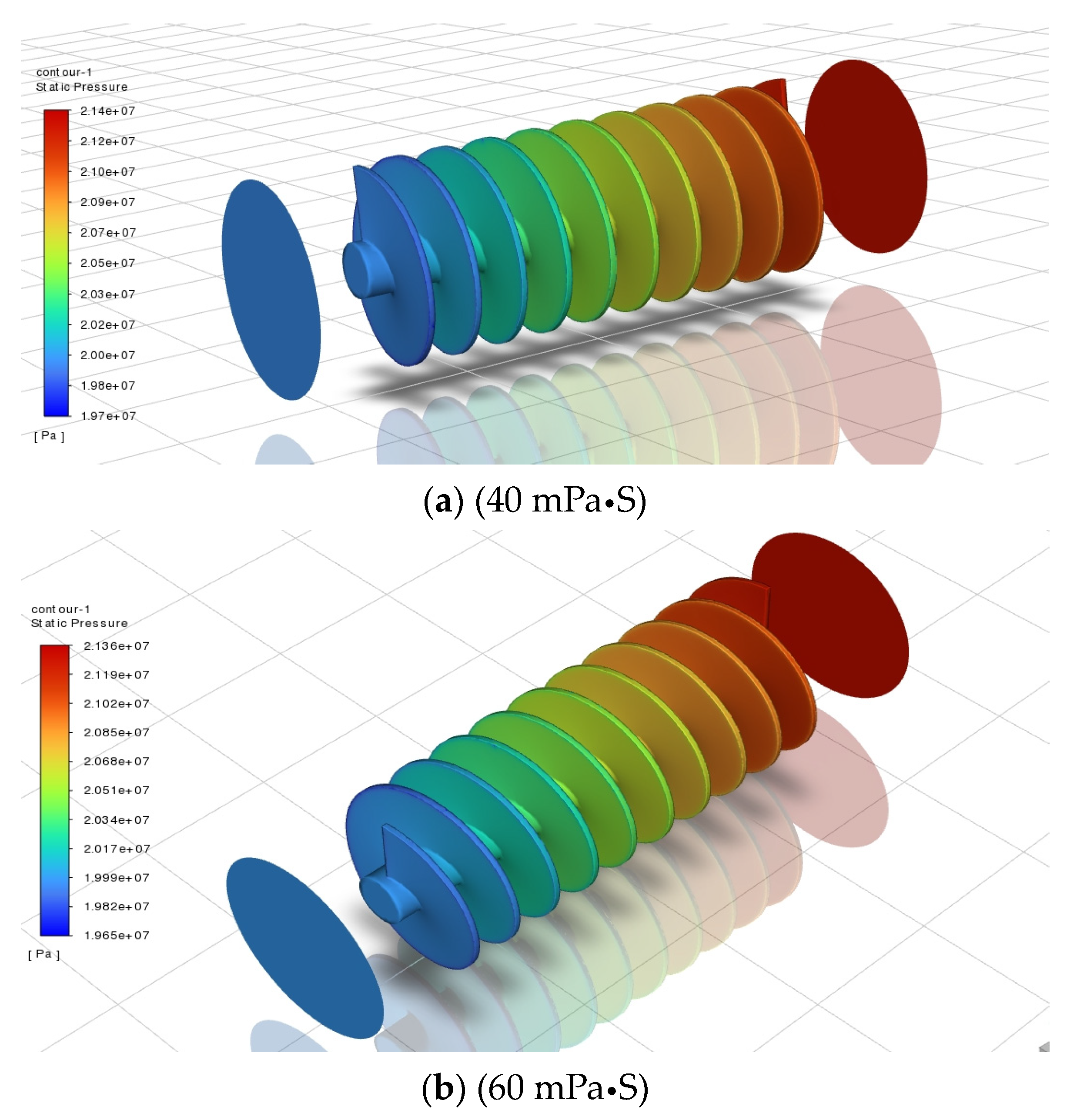
3.4. The Pressure Drop Distribution of the Liquid-Absorbing ECD-Reducing Tool at Different Viscosities

Pressure drop distribution characteristic maps (Figure 10) were simulated for the flow through the suction-type ECD-lowering tool with two different parameters of viscosity (0.04 kg/(m s)) using ANSYS-FLUENT 2022R1 as the basis for the modelling. The viscosity magnitudes, a and b, were in the order of 0.04 kg/(m s) and 0.06 kg/(m s), and two kinds of parameters were used in the pressure drop distribution characteristic diagram.
A quantitative analysis of Figure 10 reveals that the pressure drop is approximately 1.7 MPa for a viscosity of 0.04 kg/(m s) and approximately 1.71 MPa for a viscosity of 0.06 kg/(m s). The pressure drop remains almost unchanged for both conditions, indicating that the viscosity has a minimal effect on the suction-type tool. The effect of viscosity on the pressure drop is almost negligible, with the majority of variation occurring due to changes in flow rate under equal displacement.

4. Field Test

The wellhead injection temperature and pressure are defined as boundary conditions in this context. The data presented in this paper are based on field data from the Caoshe 8 well in the Jiangsu Caoshe Oilfield [8], with testing conducted in the second half of 2023 at the site in question. The measured well depth reaches up to 2600 m, the drilling bit is a 6–1/2′ (165.1 mm) PDC bit, the drilling fluid displacement is 1500 L/min–2000 L/min, and the casing OD is 9–5/8′ (244.5 mm). The drilling rod section length was 10 m, the wellbore diameter was 260.5 mm, the starting and stopping drilling speeds were 0.25 m/s, the drilling fluid viscosity was 0.04, the friction coefficient was 0.029, the surface temperature was 288.15 K, and the ground temperature gradient was 0.03 K/m [19].
The test tool is selected to have an inner diameter of 7.5 inches (190.5 mm) and an outer diameter of 9.5 inches (244.5 mm). The drilling fluid density is 1. The tool was in-stalled at a distance of 800 metres from the wellhead. Following the field test, the pressure reduction effect of the tool was found to be approximately 2 MPa, which was in line with the desired target pressure reduction value. For further details, please refer to Table 1, which contains the pressure change table for the pressure reduction tool.
As illustrated in Figure 11, the pressure value of the wellbore containing the pres-sure-reducing tool exhibits a notable fluctuation, with a reduction of approximately 1.7 MPa, which aligns with the specifications for pressure reduction in field construction.

5. Conclusions

A series of simulations conducted using ANSYS-FLUENT enabled the following conclusions to be drawn with regard to the pressure drop characteristics under different parameters.
(1)
The conventional approach proved inadequate for addressing the challenges associated with the efficient and rapid drilling of wells with narrow density windows and other complex scenarios. There is a clear need for a fundamental improvement in the existing methodology, necessitating a shift towards more sophisticated equipment and drilling techniques to effectively address the complexities inherent to the drilling process.
(2)
The density of the drilling fluid gradually increases (1.2–2.0 g/cm3) and its pressure reduction effect also increases gradually. The pressure reduction value reaches 2.3 MPa, and the density can be reasonably controlled. However, if the density is too high, the pressure in the wellbore will also be too high, which will increase the risk of tool seal failure.
(3)
As the volume of drilling fluid displaced gradually increases (1500–2500 L/in), the pressure drop value fluctuates significantly, and the pressure drop effect is more pronounced, reaching approximately 2 MPa. With the increase in drilling fluid displacement, the pressure drop effect is enhanced, and when the displacement is minimal, the tool pressure drop and shunt effects are not discernible.
(4)
At a viscosity of 0.04 kg/(m·s), the pressure drop is approximately 1.7 MPa. At a viscosity of 0.06 kg/(m·s), the pressure drop is approximately 1.71 MPa. The pressure drop remains almost unchanged at 1.71 MPa in both working conditions, indicating that the viscosity has minimal impact on the suction-type tool’s pressure drop. Instead, the flow rate ap-pears to be the primary factor influencing the pressure drop, particularly when the dis-placement is equal.
(5)
The majority of traditional pressure-relief tools require ground equipment to pro-vide the necessary power to drive the pressure-relief tool to rotate. The cost of the input equipment is considerable, and the pressure-relief effect is minimal. This paper proposes a new type of suction-type pressure-relief tool that does not require power equipment.
(6)
This paper proposes a new type of suction-type pressure-relief tool that does not require power equipment. Instead, it converts the hydraulic energy generated by circulating fluid into mechanical energy, which drives the pressure-relief tool to rotate. The pressure-relief effect reaches 2 MPa, which has an evident impact on pressure relief. Furthermore, it provides an innovative direction for addressing the challenge of high-temperature and high-pressure drilling with a narrow pressure window.
(7)
The new suction-type pressure-relief tool employs a single screw pump as the power component. The potential failure modes of the single screw pump are numerous and complex, making it challenging to accurately assess the failure risk using conventional assessment methods. Without a comprehensive risk assessment model, it is difficult to implement targeted risk reduction measures.

Author Contributions

M.R. put forward innovative ideas and grasped the research direction; X.Z. is responsible for the analysis of the step-down algorithm; R.X. is responsible for the software simulation of the step-down tool; J.W. is responsible for the construction of the physical model of the step-down tool; Z.Z. is responsible for the physical construction of the depressurisation tools; X.C. is responsible for the test site of the depressurisation tools; and L.D. provided financial assistance. All authors have read and agreed to the published version of the manuscript.

Funding

This study was funded by Dou Liangbin, funded projects: Shaanxi Province Key Research and Development Plan, project number: 2024GX-YBXM-503.

Data Availability Statement

As the project is in the development stage, the data are temporarily confidential.

Conflicts of Interest

Authors Meipeng Ren, Xingquan Zhang, Renjun Xie and Junyan Wang were employed by the company CNOOC Research Institute Ltd. The remaining authors declare that the research was conducted in the absence of any commercial or financial relationships that could be construed as a potential conflict of interest. The CNOOC Research Institute Ltd. had no role in the design of the study; in the collection, analyses, or interpretation of data; in the writing of the manuscript, or in the decision to publish the results.

References

  1. Zheng, F.; Yu, S.; Li, G.; Luo, H.; Huang, Z. Jet hydraulic depressurization experimental study. Pet. Mach. 2008, 36, 4. [Google Scholar]
  2. Yuan, G. Research Status and Performance Analysis of Jet Pump Tool for Reducing Bottom Hole Pressure Difference. Oil Drill. Technol. 2012, 40, 76–80. [Google Scholar]
  3. Zhu, H.; Deng, J.; He, Y. Hydraulic jet technology to reduce bottom hole pressure difference. J. China Univ. Pet. Nat. Sci. Ed. 2013, 37, 50–56. [Google Scholar]
  4. Dokhani, V.; Ma, Y.; Yu, M. Determination of equivalent circulating density of drilling fluids in deepwater drilling. J. Nat. Gas Sci. Eng. 2016, 34, 1096–1105. [Google Scholar] [CrossRef]
  5. Erge, O.; Ozbayoglu, E.M.; Miska, S.Z.; Yu, M.; Takach, N.; Saasen, A.; May, R. Equivalent circulating density modeling of Yield Power Law fluids validated with CFD approach. J. Pet. Sci. Eng. 2016, 140, 16–27. [Google Scholar] [CrossRef]
  6. Abdelgawad, K.Z.; Elzenary, M.; Elkatatny, S.; Mahmoud, M.; Abdulraheem, A.; Patil, S. New approach to evaluate the equivalent circulating density (ECD) using artificial intelligence techniques. J. Pet. Explor. Prod. Technol. 2019, 9, 1569–1578. [Google Scholar] [CrossRef]
  7. Huang, Y.; Yang, J.; Sheng, Y.; Guan, Z.; Luo, M. Quantitative risk assessment method for high temperature and high pressure drilling engineering in Yingqiong Basin. Offshore Oil Gas China 2019, 31, 119–124. [Google Scholar]
  8. Chen, Y.; Zhang, F.; Wu, T.; Wang, Y.; Wang, Q. Extended reach well hole cleaning and ECD control. China Sci. Technol. Pap. 2021, 16, 1017–1022. [Google Scholar]
  9. Huang, W. Study on ECD Calculation Method of Changning Shale Gas Horizontal Well. Master’s Thesis, China University of Petroleum, Beijing, China, 2021. [Google Scholar]
  10. Duan, H. Study on the Calculation Method of High Temperature and High Pressure ECD of Oil-Based Drilling Fluid in Xinjiang Oilfield. Master’s Thesis, China University of Petroleum, Beijing, China, 2022. [Google Scholar]
  11. Foued, B.; Vamegh, R.; Nidhal, B. Impact of hole cleaning and drilling performanceon the equivalent circulating density. J. Pet. Sci. Eng. 2022, 211, 110150. [Google Scholar]
  12. Gao, Y.; Dong, H.; Hu, Y.; Chen, C.; Cheng, L. Prediction model and application of drilling fluid equivalent circulation density in deepwater HTHP wells. Spec. Oil Gas Reserv. 2022, 29, 38–143. [Google Scholar]
  13. Wei, X. Key points of ECD check and control technology for high temperature and high pressure wells. Chem. Manag. 2022, 18, 157–160. [Google Scholar]
  14. Li, W.; Luo, M.; Huang, H.; Li, J.; Xiao, P. Annular ECD comprehensive calculation model of high temperature and high pressure slim hole horizontal well. Pet. Drill. Prod. Technol. 2023, 45, 259–268. [Google Scholar]
  15. Okonkwo, F.I.S.; Joel, F.O. Modelling the Effects of Temperature and Pressure on Equivalent Circulating Density (ECD) During Drilling Operations Using Artificial Neural Networks. J. Eng. Res. Rep. 2023, 25, 70–82. [Google Scholar] [CrossRef]
  16. Al-Rubaii, M.; Al-Shargabi, M.; Aldahlawi, B.; Al-Shehri, D.; Minaev, K.M. A Developed Robust Model and Artificial Intelligence Techniques to Predict Drilling Fluid Density and Equivalent Circulation Density in Real Time. Sensors 2023, 23, 6594. [Google Scholar] [CrossRef] [PubMed]
  17. Hao, X.; He, Y.; Cheng, B. Characteristics of drilling fluid equivalent circulating density distribution in double-gradient drilling wellbore with double-layer continuous tubing. Oil Drill. Process 2023, 45, 418–423. [Google Scholar]
  18. Liang, X.; Wei, K.; Fang, Q. Density calculation model and influence analysis of high temperature and high pressure oil-based drilling fluid. Petrochem. Appl. 2023, 42, 64–69. [Google Scholar]
  19. Zhang, Y.; Tang, R. Study of distribution of wellbore pressure and temperature of CO2 injection well. Offshore Oil 2007, 27, 59–64. [Google Scholar]
Figure 1. A schematic diagram of the structure of the components of the suction-type ECD-lowering tool. The components of the tool are the stator (a), screw vane (b), universal joint (c) and rotor (d).
Processes 12 02017 g001
Figure 2. The overall structure of the suction-type ECD-lowering tool. 1: Shaft inlet; 2: import of depressurisation tools; 3: rotating blades; 4: tool jacket; 5: universal axis; 6: prevent the assembly; 7: sealing ring; 8: screw rotor; 9: screw stator; 10: tool export; 11: shaft outlet.
Processes 12 02017 g002
Figure 3. Grid division.
Processes 12 02017 g003
Figure 4. Tool grid partition section diagram.
Processes 12 02017 g004
Figure 5. Tool simulation flow direction.
Processes 12 02017 g005
Figure 6. Pressure drop distribution of different drilling fluid density.
Processes 12 02017 g006
Figure 7. Fluid flow direction.
Processes 12 02017 g007
Figure 8. Pressure drop distribution characteristics and fluid flow distribution characteristics at different displacement.
Processes 12 02017 g008
Figure 9. Pressure drop distribution of suction tool under different drilling fluid displacement.
Processes 12 02017 g009
Figure 10. Pressure drop distribution characteristics of different viscosities.
Processes 12 02017 g010
Figure 11. Wellbore pressure with depressurisation tool.
Processes 12 02017 g011
Table 1. Pressure change table of depressurisation tool.
Well Depth/mNormal Drilling Pressure/MPaPressure Relief Tool Pressure/MPaDepressurisation Value/MPa
80011.7610.081.68
100014.7012.961.74
120017.6415.981.66
140020.5818.811.77
160023.5221.701.82
180026.4624.871.59
200029.4027.481.92
220032.3430.322.02
240035.2833.391.89
260038.2236.231.99
Disclaimer/Publisher’s Note: The statements, opinions and data contained in all publications are solely those of the individual author(s) and contributor(s) and not of MDPI and/or the editor(s). MDPI and/or the editor(s) disclaim responsibility for any injury to people or property resulting from any ideas, methods, instructions or products referred to in the content.

