Abstract
The research presented in this work explores two methods for synthesizing supported metal catalysts: wet impregnation method (IM) and sol–gel auto-combustion method (AC). These techniques were used to create a series of magnesium oxide (MgO)-based materials, including pure MgO and MgO-supported chromia catalysts, CrMgX, varying the weight percentage of chromium. The specific materials synthesized are unmodified MgO; MgO loaded with 1, 3, and 5 wt% CrO3 via impregnation; and counterparts prepared with the same loadings using Cr (NO3)3 via sol–gel auto-combustion method. After synthesis, various characterization techniques were utilized to analyze the samples comprehensively. These methods encompass FTIR, Raman spectroscopy, XRD, SEM, and BET surface area analysis. The investigation revealed a clear distinction between the two synthesis methods. While the impregnation method resulted in a greater degree of interaction between the metal oxides, the sol–gel auto-combustion approach yielded materials with superior textural and morphological properties. Significantly, the BET analysis demonstrated that all the MgO and CrMgX catalysts possessed high surface areas. In particular, the CrMg 3 (AC) catalysts synthesized via sol–gel auto-combustion exhibited an exceptional surface area of 72 m2 g−1, which is the highest value reported for such materials in the existing literature. This remarkable surface area directly translates to enhanced catalytic activity, making these materials strong contenders for various industrial applications. The research effectively highlights the potential of sol–gel auto-combustion as a method for producing catalysts with outstanding textural properties, a crucial factor for developing high-performance catalysts for industrial processes.
1. Introduction
Chromium stands out among the 3D transition metals due to its diverse oxidation states, coordination numbers, and molecular structures. Understanding the behavior of chromium species on inorganic oxide surfaces is crucial for gaining insights into its environmental interactions, its colloid behavior, and its roles as a component in chromium-based heterogeneous catalysts. In nature, chromium is commonly found in minerals and geochemical deposits, where it can exist as surface species or be released into the environment through processes such as erosion and weathering. In industrial settings, chromium compounds are extensively used in activities like leather tanning, electroplating, and pigment production, resulting in their presence in solid wastes and wastewater. Chromium oxides exhibit high solubility and reactivity, undergoing redox reactions and various transformations at the interface between solids and water [1,2,3]. In natural environments, magnesium oxides play the role of oxidizing Cr3+, while organic constituents in soils contribute to the reduction of mobile Cr6+ to the less mobile Cr3+.
Chromium-based catalysts are pivotal in various industrial processes, featuring chromium oxides supported on inorganic substrates like silica, alumina, and molecular sieves. They serve essential roles across industries, including polymerization, hydrogenation, alcohol dehydration, hydrocarbon dehydrogenation, paraffin dehydrocyclization, water–gas shift reaction, and the treatment of chlorinated volatile compounds through decomposition and fluorination. These catalysts are integral due to their versatility and efficiency in catalyzing crucial chemical transformations in industrial settings [4,5].
Chromium displays a diverse array of coordination numbers, ranging from 2 to 6, and exhibits various oxidation states, spanning from Cr2+ to Cr6+. Among these, Cr3+ is notably the most stable and extensively researched. In contrast, Cr6+ typically forms tetrahedral polyoxoanions but is less prevalent than Cr3+ in practical applications due to its high oxidation potential. Cr5+ and Cr4+ are comparatively unstable, with Cr5+ prone to disproportionation into Cr3+ and Cr2+, in which Cr2+, characterized by its strong reducing nature, remains stable under anaerobic conditions but reacts vigorously in the presence of oxygen. In aqueous solutions, the predominant oxidation states of chromium are Cr6+, Cr3+, and Cr2+. Chromium oxides exhibit a wide variety depending on environmental conditions such as pH, concentration, and redox potential. For instance, chromium oxides like CrO3, CrO2, and Cr2O3, as well as intermediate species such as Cr3O8, Cr2O5, and Cr5O12, illustrate the complex chemistry of chromium. CrO3, structured with chains of CrO4 tetrahedra, undergoes thermal decomposition, losing oxygen to yield Cr2O3, which adopts a stable spinel structure. CrO2, forming during the transformation of CrO3 to Cr2O3, possesses a rutile structure, highlighting its role in chromium oxide chemistry [6,7].
Upon heating in air, a freshly prepared catalyst undergoes significant transformations. Initially, water molecules that are adsorbed on the catalyst support and around chromium are desorbed. Concurrently, any Cr3+ ions present are oxidized to Cr6+. This oxidation process leads to the formation of dehydrated chromium oxide species. At lower chromium loadings, these species bind to the support through esterification with hydroxyl groups present on the inorganic oxide surface, thereby forming surface-bound Cr species. Under hydrated conditions, the catalyst’s amorphous oxide surface becomes coated with a thin film of water. The density of hydroxyl groups on this surface is influenced by the pH of the surrounding environment. Commercially available chromium oxide catalysts typically consist of chromium oxide particles dispersed on a porous support. These catalysts often incorporate dopants that help manage deactivation and enhance selectivity in various chemical processes [8,9,10]. Research attention has historically focused on chromium oxide systems supported by materials such as MgO. Studies have shown that magnesium and chromium oxides can react at elevated temperatures to produce a spinel structure. Investigations into the effects of different chromium concentrations on the transformation of MgO and Cr2O3 have also been conducted.
Furthermore, chromia supported on MgF2 catalysts have been tested for applications such as CO oxidation at room temperature and in the dehydrogenation of cyclohexane to synthesize benzene. Impregnation and co-precipitation are commonly employed methods for synthesizing MgO-supported chromia catalysts. Deposition of aqueous precursors on oxide supports is generally achieved by the impregnation method. This involves contacting the solution containing the catalyst precursor with the solid support. If the solution volume equals or is less than the support volume, it is called incipient wetness. For weak interactions between the active precursor and the support, incipient wetness impregnation, followed by drying, can achieve high precursor loadings, limited by precursor solubility. Higher weight loadings require higher concentrations, which may lower the solution pH and disrupt the support. In the absence of strong interaction, drying can cause redistribution of the impregnated species, leading to a homogenous cover of the active material on the final catalyst [11,12,13,14].
Precipitate formation from a homogeneous solution can be achieved by changing the temperature or solvent, via solvent evaporation, or through chemical processes. This involves two main steps: nucleation, the formation of the smallest stable particles; and growth, where these particles agglomerate. Secondary processes, like Ostwald ripening and colloidal particle agglomeration due to Brownian motion, can alter the precipitate’s properties. Ostwald ripening causes smaller particles to dissolve and larger ones to grow. Nano-scale MgO can be synthesized through solid-phase, gas-phase, or liquid-phase techniques [15,16,17]. The solid-phase approach, encompassing mechanical methods and solid-state reactions, typically fails to produce particles uniformly smaller than 100 nm. In contrast, the gas-phase method, involving physical and chemical vapor deposition, offers precise control over grain size. However, challenges such as complex product retrieval and environmental concerns are associated with this method. Each synthesis route presents distinct advantages and limitations, influencing the choice of method based on specific application requirements and environmental considerations [18,19,20].
The liquid-phase method, commonly used, includes direct-precipitation, co-precipitation, and sol–gel techniques. Direct precipitation results in large, unevenly sized grains. Co-precipitation produces uniform, easy-to-filter precipitates with small particle sizes but low production rates. The sol–gel method, which uses metal–organic or inorganic materials, allows better control of the microstructure and particle size. Recently, sol–gel combined with auto-combustion, a thermally induced redox reaction, has been effective in synthesizing nano-scale oxides, producing fluffy powders upon combustion. This investigation focuses on synthesizing magnesium-supported chromium catalysts using impregnation and sol–gel auto-combustion methods and characterizing their structural features.
2. Materials and Methods
2.1. Materials
Citric acid, chromium oxide, chromium nitrate, and magnesium nitrate were acquired from Daejung Chemicals Co., Ltd., Siheung-si, Republic of Korea. Ammonium hydroxide was procured from Sigma-Aldrich, Seoul, Republic of Korea. All chemicals were utilized without further purification.
2.1.1. A One-Step Technique for Magnesium Oxide Production: Sol–Gel Auto-Combustion
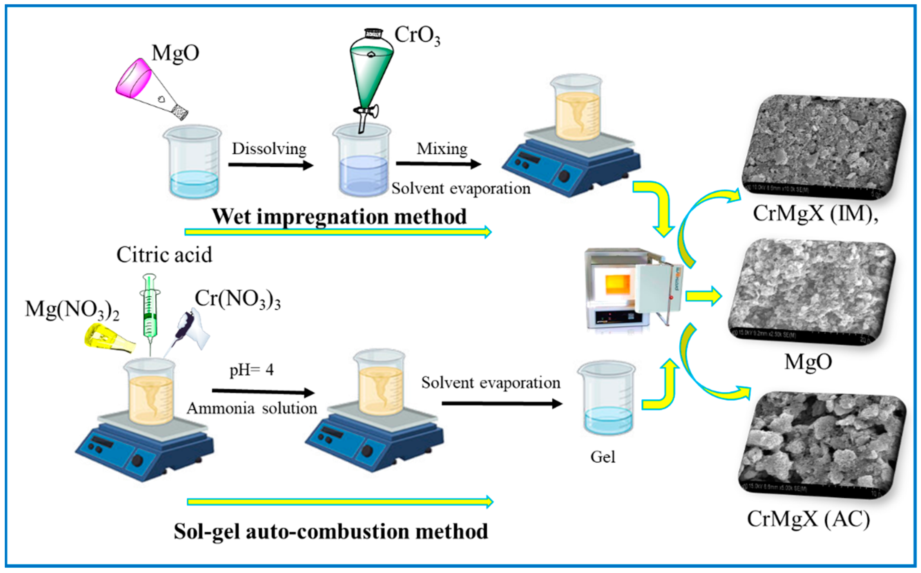
Magnesium oxide (MgO) was synthesized via the sol–gel auto-combustion method. In the first step, citric acid was added to a 0.4 mol/L solution of magnesium nitrate Mg(NO3)2 in a molar ratio of 4:1. Subsequently, ammonia was introduced to adjust the pH of the solution to approximately neutral. The solution was then evaporated at 80 °C, using a thermostatic water bath, until it formed a more concentrated gel-like substance. The resulting gel was dried at 120 °C in a vacuum oven to remove all traces of water, resulting in the formation of a dry gel. Following this, the dry gel underwent a two-step calcination process. Initially, it was pre-calcined at 150 °C for 1.5 h to initiate combustion and eliminate any remaining organic components. This step prepared the material for the final transformation. The pre-calcined gel was then subjected to a final calcination at 600 °C for 3 h to promote the complete conversion to pure magnesium oxide. This method ensures the controlled formation of MgO with high purity, leveraging the sol–gel approach for precise control over the chemical composition and morphology of the final product. The sequential steps of citric acid addition, pH adjustment, gel formation, drying, and calcination at progressively higher temperatures facilitate the transformation from precursor chemicals to the desired oxide phase. The resulting MgO product is suitable for various applications, including catalysis, ceramics, and electronic materials, owing to its purity and controlled particle size achieved through this meticulous synthesis process.
2.1.2. Synthesis of CrOx/MgO by Impregnation Method
The synthesis of CrOx/MgO composites containing 1% chromium by weight was carried out using the impregnation method. Initially, a solution was prepared by dissolving 0.1 g of CrO3 in 25 mL of water. To this solution, 0.9 g of MgO, previously synthesized via the sol–gel auto-combustion (SGAC) technique, was added. The mixture was then stirred and heated to 80 °C until the solvent evaporated, yielding a dried composite. Subsequently, the dried sample was subjected to overnight drying in an air oven at 120 °C. Finally, calcination was performed at 600 °C for 3 h. The resulting materials were designated as CrMgX (IM), where ‘X’ denotes the chromium weight percentage in the composite and ‘IM’ denotes the impregnation method.
2.1.3. Synthesis of CrOx/MgO by Sol–Gel Auto-Combustion Method
The synthesis of CrOx/MgO via the sol–gel auto-combustion method begins with the preparation of a 1 wt% CrOx/MgO composite. Initially, 84.15 mL of a 0.04753 M Mg(NO3)2 solution was diluted to 100 mL. To this solution, 30.72 g of citric acid and 3.2042 g of Cr(NO3)3 were added, and the pH was carefully adjusted to approximately 4 using small amounts of ammonia. The resulting mixture was then subjected to evaporation at 80 °C in a thermostatic water bath until a dry gel was formed. Subsequently, the gel was dried further at 120 °C in a vacuum oven. Following drying, the gel undergoes pre-calcination at 150 °C for 1.5 h, followed by a calcination process at 600 °C for 3 h. The samples obtained from this process are denoted as CrMgX (AC), where ‘X’ denotes the chromium weight percentage, and ‘AC’ denotes the sol–gel auto-combustion method. This meticulous procedure ensures the formation of the desired CrOx/MgO composite with controlled properties suitable for various applications in catalysis and materials science.
2.2. Characterization
2.2.1. Fourier-Transform Infrared Spectroscopy (FTIR)
For the infrared absorption spectra of both untreated and plasma-treated PTFE samples, a PerkinElmer MB3000 ATR FTIR spectrometer (Waltham, MA, USA) was employed. The device covered a spectral range from 500 to 4000 cm−1. To maintain consistency in the data, spectra were obtained from three different spots on each PTFE sample and placed on the sample disc.
2.2.2. Raman Spectroscopy
Raman spectroscopy was conducted using a Horiba XploRA Micro-Raman spectrophotometer in Palaiseau, France. This method examines the vibrational modes of molecules, offering complementary data to FTIR. The Raman spectra ranged from 500 to 4000 cm−1, allowing for the investigation of similar functional groups as FTIR, but with potentially different selection rules.
2.2.3. X-ray Diffraction (XRD)
X-ray diffraction (XRD) analysis was carried out using a PANalytical X’Pert3 MRD diffractometer, Panalytical (Xpert Pro), with monochromatized Cu Kα radiation. The scans, covering angles from 10 to 90° (2θ), revealed details about the crystalline structure and phase composition of the samples.
2.2.4. Electron Microscopy
Field Emission Scanning Electron Microscopy (FESEM), Hitachi (S-4800), Tokyo, Japan, with energy-dispersive X-ray spectroscopy (EDS) provided high-resolution surface images at various magnifications (from 1000× to 10,000×). The EDS component facilitated the elemental analysis at specific points on the sample surface. The FESEM operated at an accelerating voltage of 10 kV and maintained a working distance of approximately 8–9 mm.
2.2.5. BET Analysis
Surface area, pore size, and pore volume were assessed through nitrogen adsorption–desorption isotherms at −197 °C, using a Micromeritics ASAP 2000 instrument, Micromeritics (3-FLEX), Norcross, GA, USA. Samples were pre-treated by drying at 120 °C and evacuated in flowing argon at 140 °C before the measurements.
3. Results and Discussions
3.1. Fourier-Transform Infrared (FTIR) Spectroscopy Analysis
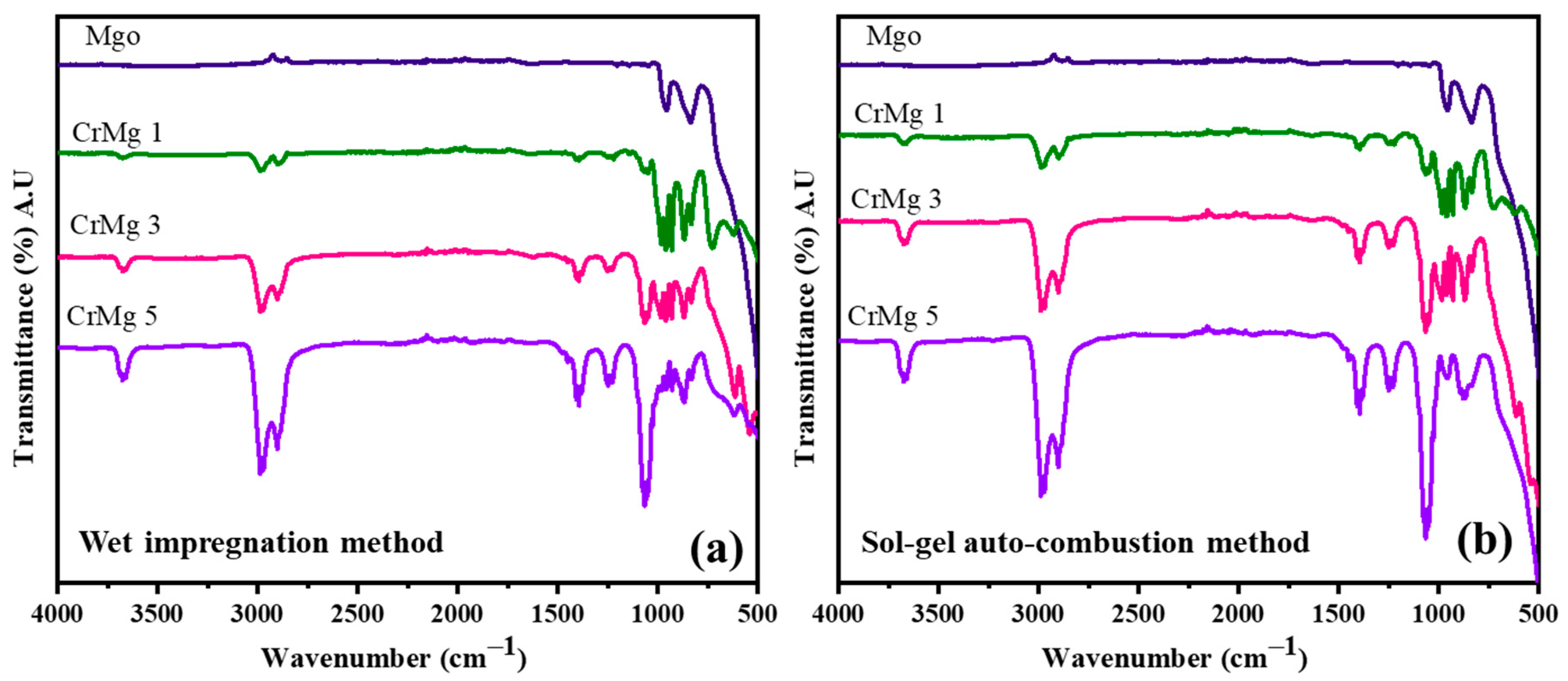
The synthesis of MgO, CrMgX (IM), and CrMgX (AC) by the wet impregnation and sol–gel auto-combustion methods is depicted in Scheme 1. Fourier-Transform Infrared (FTIR) spectroscopy was employed to analyze the synthesized samples: MgO, CrMgX (IM), and CrMgX (AC). Figure 1a,b display the spectra of the synthesized materials, revealing significant information about their chemical compositions and structural properties. An examination of these spectra collectively identifies distinct absorption bands indicative of various functional groups and chemical interactions within the samples. Beginning with MgO sample, the broad peak around 500 cm−1 represents the characteristic bending modes of surface hydroxyl groups on MgO and the vibrations of the Mg-O group. It is a general observation that MgO is susceptible to hydroxyl and carbonyl adsorption on its surface. The additional peaks around 850 cm−1 correspond to the carbonyl species adsorbed on the surface of MgO. Interestingly, the absence of a broad absorption peak around 3600 cm−1, corresponding to the acidic hydroxyl group of citric acid (used in the synthesis process), indicates that the final product is pure MgO and does not contain any residues of citric acid [3,6,20]. When moving to the FTIR spectra of CrMgX (IM) and CrMgX (AC), it is evident that both the wet impregnation and sol–gel auto-combustion methods did not show any appreciable difference between them. A small absorption peak centered at 3620 cm−1 was observed, attributed to the surface adsorbed hydroxyl (-OH) groups, whose intensity increases with the increased loading of chromium. Furthermore, additional bands were observed at 1416 and 1269 cm−1, which are assigned to the symmetric and asymmetric stretching vibrational modes of the carbonyl group, respectively. Obviously, the intensity of the peaks also becomes increased with the additional loading of chromium, meaning that more carbonyl groups are adsorbed on the CrMgX surface with increased chromium loading.
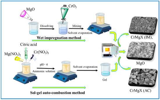
Scheme 1.
Synthesis of MgO, CrMgX (IM), and CrMgX (AC).

Figure 1.
FTIR spectrum: (a) CrMgX (IM) and (b) CrMgX (AC).
A further analysis of these spectra reveals distinct bands at 915, 1002, and 1075 cm−1, which correspond to specific chromium species. The increased intensity of these bands indicates a reduction in Cr6+ species, possibly due to an increase in Cr3+ species as the chromia content exceeds the support’s dispersion capacity. This observation underscores the influence of chromia content on the oxidation states of chromium within the material. Introducing chromia into CrMg 1 results in the appearance of new bands at 550 cm−1 and an alteration in the band at 500 cm−1. With a higher chromia content, both in CrMg 3 and CrMg 5, there is a noticeable reduction in the intensity of the band at 500 cm−1. This suggests that surface hydroxyl groups on MgO are consumed during the esterification process involving the chromia phase, while the band at 550 cm−1 likely corresponds to bending modes of hydroxyl groups within the free chromia phase [9,14,21]. Overall, FTIR spectroscopy has provided valuable insights into the structural changes and chemical interactions occurring within MgO, CrMg (IM), and CrMg (AC) samples. The presence and consumption of hydroxyl groups, as well as variations in chromium oxidation states, are crucial findings for understanding the dynamic interactions between chromia and the MgO support in these materials. These observations contribute significantly to the broader understanding of catalyst synthesis and performance in various chemical processes.
3.2. Raman Spectroscopy
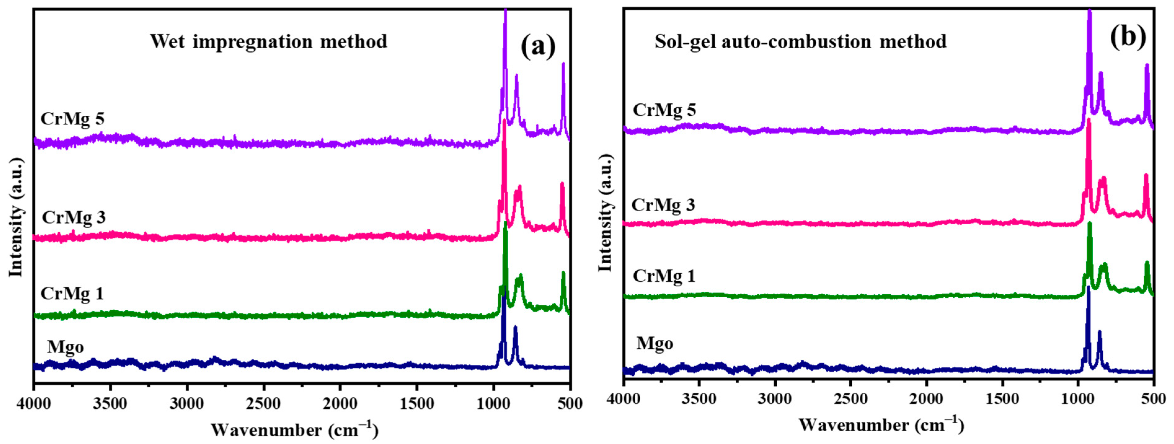
Raman spectroscopic analyses were employed to investigate CrMgX samples synthesized using two distinct methods: sol–gel auto-combustion (AC) and impregnation (IM). The spectra corresponding to these samples are depicted in Figure 2a,b. In the case of CrMg 3 and CrMg 5 (IM), notable shifts in all bands compared to CrMg 1 (IM) were observed, attributed to enhanced interaction between oxygen from chromate ions and the support, particularly with increased chromium content [8,10]. For instance, bands at 844 and 852 cm−1, associated with polymeric chromium species, exhibited increased intensity relative to CrMg 1 (IM), indicating a higher presence of such species with higher chromium loading. Similarly, bands at 953 and 966 cm−1, corresponding to νss(CrO2) vibrations of stabilized tetrameric chromium species, also showed higher intensity in CrMg 3 (IM) and CrMg 5 (IM). This contrasted with CrMg 1 (IM), where these bands were less pronounced, suggesting a greater abundance of tetrameric species in the sample with increased chromium loading. Interestingly, the ratio of intensities between the 852 and 871 cm−1 band remained consistent for all the samples, indicating uniform stabilization of monochromate species on the MgO support, while additional chromium stabilized as polychromate species in CrMg 3 (IM) and CrMg 5 (IM). Moreover, bands at 920 and 841 cm−1 in the spectra indicated the presence of Cr-O-Cr stretching modes, further confirming the stabilization of polychromate species [22,23]. The higher intensity ratio of the bands at 841 cm−1 to the bands at 920 cm−1 in CrMg 3 (IM) and CrMg 5 (IM) underscored the increased stabilization of polychromate species in this sample, implying a consistent amount of mononuclear chromyl species stabilized on the MgO surface across different chromium contents in CrMg X (IM) samples [13,14,15,16]. This highlighted a strong interaction between the acidic hydroxyl groups of CrO3 precursor and the basic hydroxyl groups of MgO.
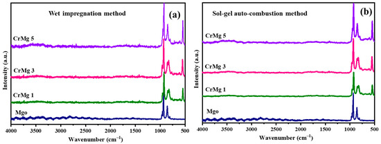
Figure 2.
Raman spectrum: (a) CrMgX (IM) and (b) CrMgX (AC).
In contrast, for CrMg 3 (AC) and CrMg 5 (AC), similar slight shifts were observed in all bands relative to CrMg 1 (AC), attributed to increased interaction between oxygen from chromate ions and the support at higher loading. Intense bands observed in the region between 800 and 960 cm−1 in CrMg 3 (AC) and CrMg 5 (AC) indicated the presence of Cr-O-Cr groups, suggesting the presence of tri- and tetrameric chromium species. Conversely, fewer bands were observed in CrMg 1 (AC), suggesting a lower amount of polychromate species that increased with chromium loading. Bands around 987 and 976 cm−1 were attributed to symmetric side bands of peroxo species, indicating the formation of coordinately unsaturated chromium sites due to dehydroxylation at 600 °C, possibly occurring between surface hydroxyl groups of the support or between active chromium and support phases, resulting in dehydrated surface Cr=O species. Additionally, a prominent band at 907 cm−1 was observed in all the CrMgX (AC) samples, corresponding to the stretching mode of the Cr6+=O group [14], confirming the presence of Cr(VI) state, which was consistent with the yellowish coloration of the samples. In contrast, CrMgX (IM) samples tended towards greenish hues, indicating a lesser stabilization of Cr6+ on impregnated samples. The absence of bands at 1048 cm−1 with a weak shoulder at 1041 cm−1 in CrMg 3 (AC) and CrMg 5 (AC) suggested a decrease in mononuclear chromyl species with increased chromium loading, potentially due to the formation of polychromate species. A comparative analysis of Raman profiles between CrMg 1 (AC) and CrMg 1 (IM) revealed a higher intensity of the 871 cm−1 band, characteristic of monomeric chromium oxo species, in CrMg 1 (AC), highlighting the superior performance of the sol–gel auto-combustion method over impregnation in stabilizing such species. Similarly, our comparison between CrMg 3 (AC), CrMg 5 (AC) and CrMg 1 (IM) suggested a lack of stabilization of monomeric chromium species on the support surface in the former. Bands at 1006, 1014, and 1035 cm−1 were associated with mono-oxo chromyl species with a chromium oxidation state near +5 [8,13,24].
Overall, the Raman profiles of CrMg 1 (AC) indicated the stabilization of mononuclear chromyl species, whereas CrMg 3 (AC) and CrMg 5 (AC) stabilized polymeric chromyl species, possibly due to interactions between Cr(NO3)2 and Mg(NO3)2, which reduced basic sites on the support surface and promoted polymer chain growth. This interaction correlated with a relatively lower hydroxyl density in samples prepared via the sol–gel auto-combustion route, highlighting distinct spectroscopic signatures influenced by the synthesis method and chromium loading.
3.3. X-ray Diffraction Studies
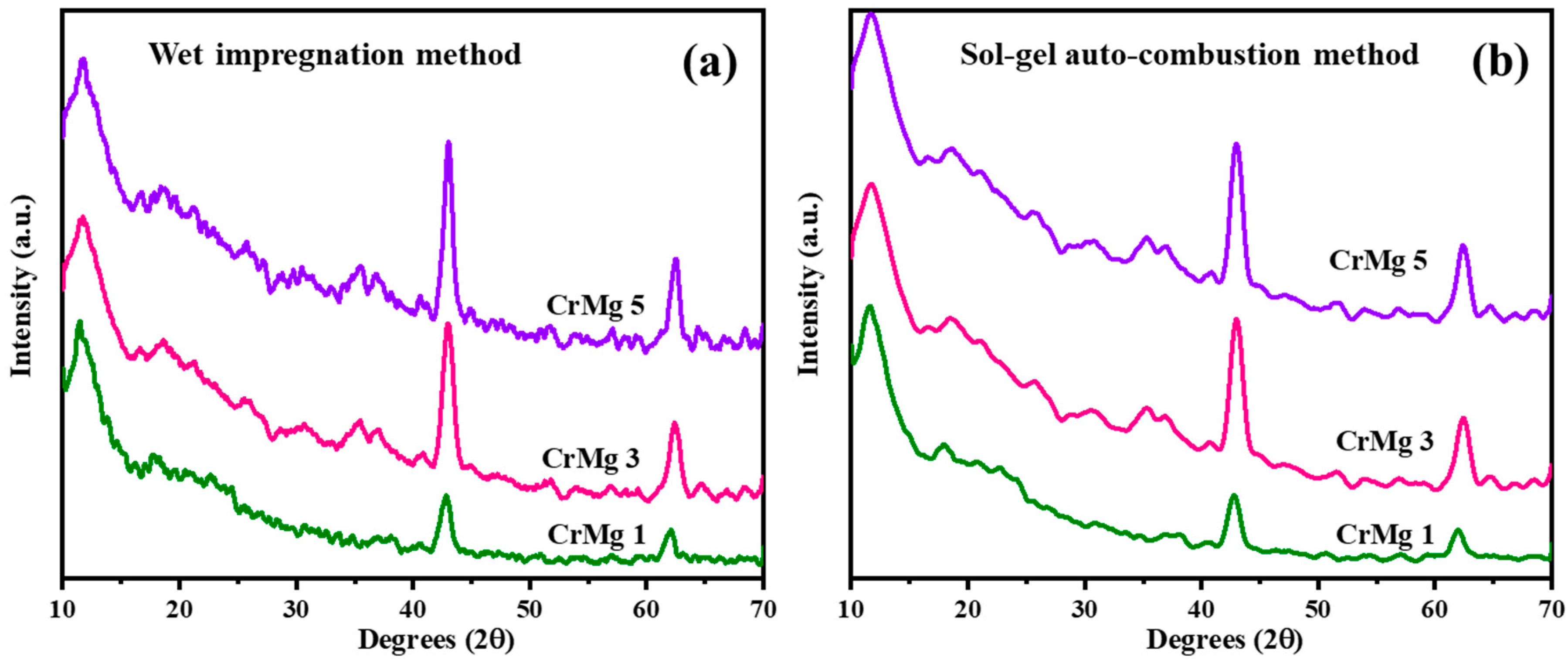
X-ray diffraction (XRD) measurements were conducted for CrMgX (IM) and CrMgX (AC), with the results shown in Figure 3a,b. When comparing 1, 3, and 5 wt% CrMg samples prepared via the impregnation method, it is observed that the intensity of MgO peaks at 2θ = 42° and 62°, corresponding to the [200] and [220] planes, increases. Additionally, a diffraction peak at 2θ = 11.7°, with a d-spacing value of 7.55 Å, becomes more prominent with higher chromia loading, indicating a chromia-related phase. For CrMg samples prepared using the sol–gel auto-combustion method, the MgO peaks are less intense.

Figure 3.
XRD spectrum: (a) CrMgX (IM) and (b) CrMgX (AC).
Comparing the diffraction patterns of CrMgX (IM) and CrMgX (AC) samples reveals notable findings. All CrMg samples, irrespective of their preparation method, display a characteristic peak with a d-spacing value of 7.7 Å as their most intense peak. CrMg 1 (IM), CrMg 3 (IM), and CrMg 5 (IM) show diffraction patterns with a peak with a d-spacing value of 4.8130 Å, consistent with the formation of CrMg2O4, according to standard data. In addition to it, the crystallite size calculated using the Scherrer equation was found to be 7.3 nm for CrMg 3 (IM) and 9.04 nm for CrMg 3 (AC). Furthermore, the lattice strain calculated using the Williamson–Hall method was found to be 13.27 × 10⁻³ for CrMg 3 (IM) and 15.19 × 10⁻³ for CrMg 3 (AC). Conversely, the CrMg samples prepared via the sol–gel auto-combustion method do not show evidence of CrMg2O4 spinel formation, implying that, under the given preparation conditions, chromia remains as a surface coating on the support [15,22,25]. This suppression of solid-state reaction is advantageous in this context.
3.4. SEM Analysis
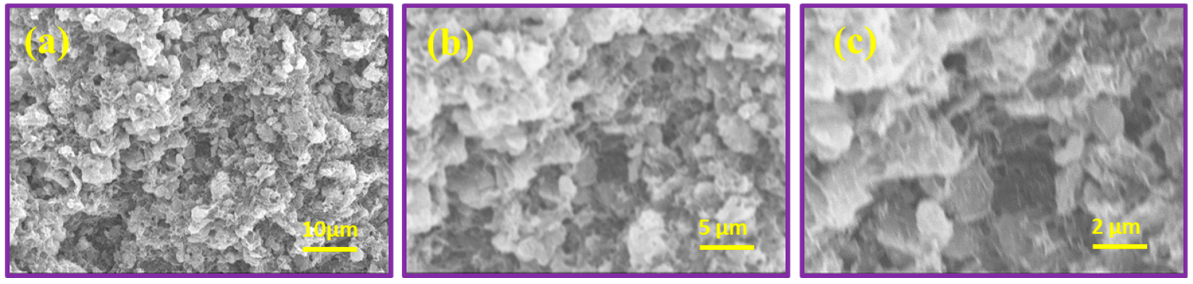
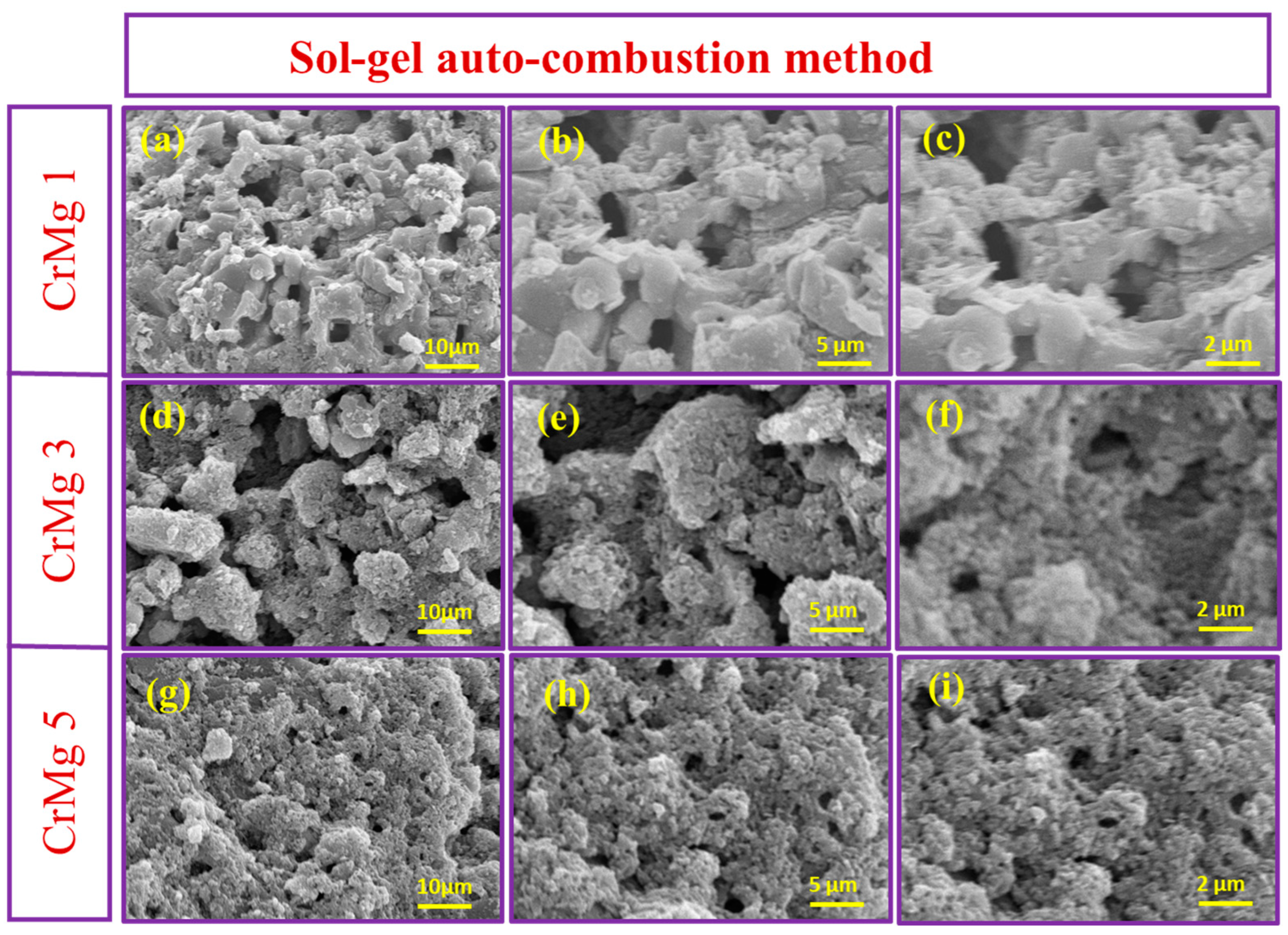
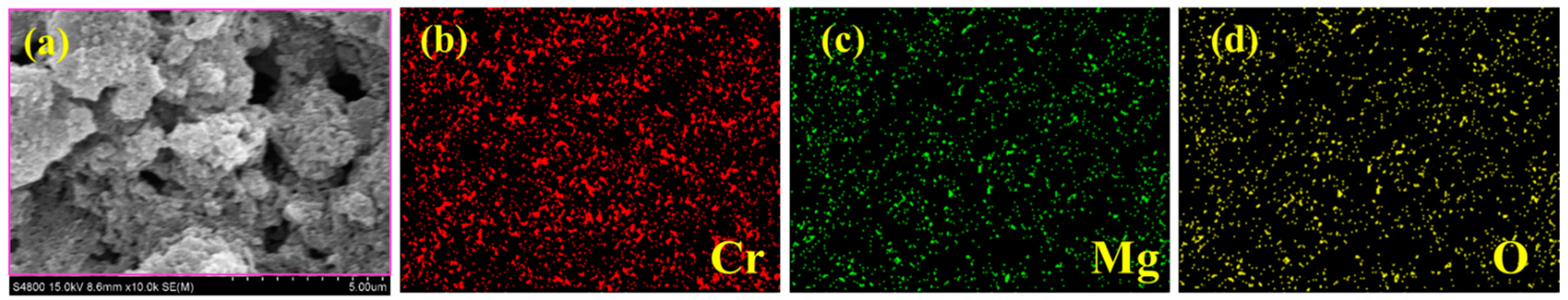
The surface morphology of MgO, CrMgX (IM), and CrMgX (AC) samples was analyzed using SEM. Figure 4 displays the SEM images of MgO at different magnifications. It is evident that MgO possesses a porous morphology obtained via the sol–gel process. This porous morphology unambiguously increased the surface area of MgO to 112 m2 g−1, as evident from the BET analysis. Figure 5 and Figure 6 display the SEM images of CrMgX (IM) and CrMgX (AC) catalysts. As could be observed, the surface morphology of MgO was completely modified upon loading with chromium. The CrMgX catalysts synthesized from both the wet impregnation and sol–gel auto-combustion methods exhibit a completely different morphology from both of these methods, owing to different precursors and methodologies, and from pure MgO. The CrMgX (IM) catalysts derived from the wet impregnation method display a spongy morphology, which leads to agglomeration at a higher loading of chromium (5 wt%). Interestingly, the sol–gel auto-combustion method creates a proper morphology for CrMgX (AC) catalysts, where uniform coating and dispersion of chromium over MgO support could be visualized. And, also, 3 wt% loading of chromium in both the CrMg 3 (IM) and CrMg 3 (AC) catalysts resulted in proper morphology when compared with the other loading. The presence of these elements is further confirmed by elemental mapping (Figure 7).
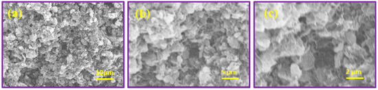
Figure 4.
SEM images of MgO at different magnifications at different magnifications (a–c).
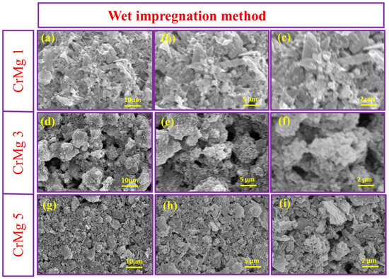
Figure 5.
SEM images of (a–c) CrMg 1, (d–f) CrMg 3 and (g–i) CrMg 5 at different magnifications.
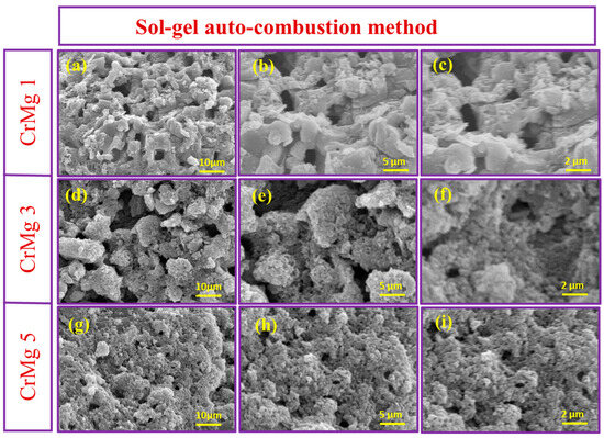
Figure 6.
SEM images of (a–c) CrMg 1, (d–f) CrMg 3 and (g–i) CrMg 5 at different magnifications.
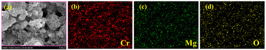
Figure 7.
(a) SEM image and (b–d) elemental mapping CrMg3 (AC).
3.5. BET Studies
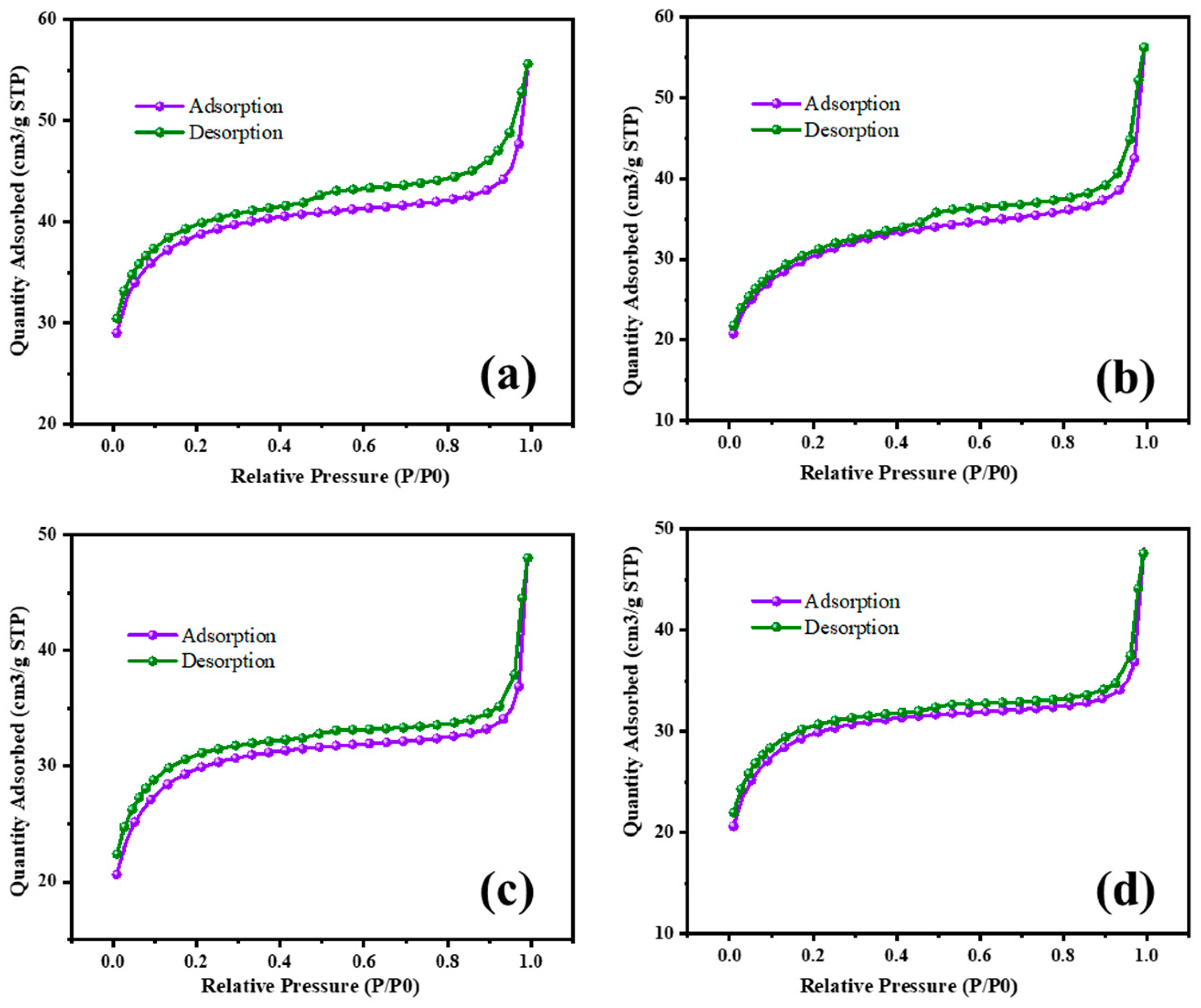
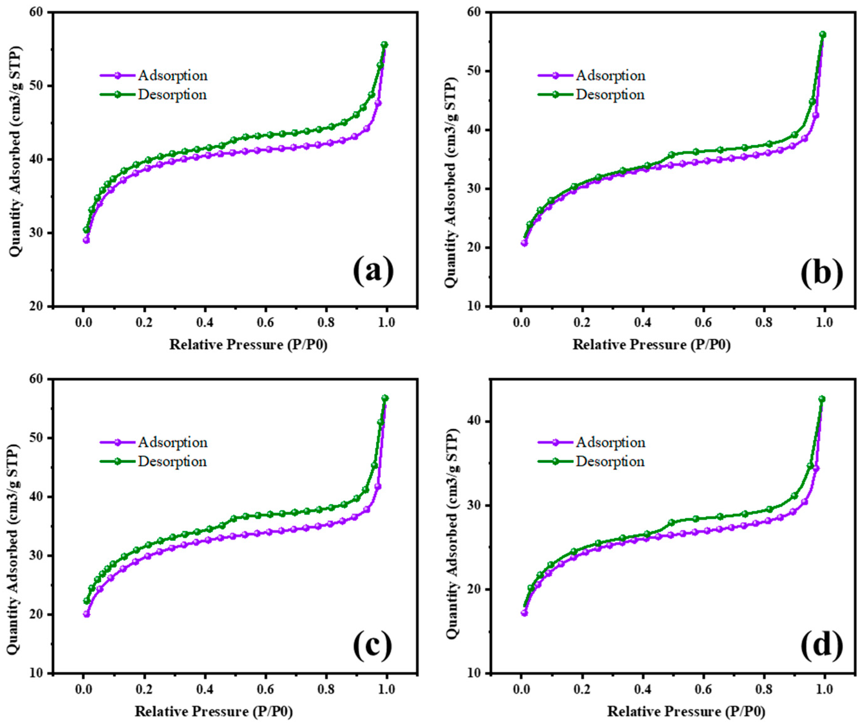
The surface area characterization of MgO and MgO supported with chromia (CrMgX), using different preparation methods, reveals significant insights into their textural properties and potential applications in catalysis. Figure 8 and Figure 9 display the N2 adsorption–desorption isotherms of the MgO and CrMgX samples. MgO synthesized via the sol–gel auto-combustion method exhibited a surface area of 112 m2 g−1, whereas MgO supported with chromia prepared via the impregnation method showed a surface area of 75 m2 g−1 for CrMg 1 (IM), 61 m2 g−1 for CrMg 3 (IM) and 56 m2 g−1 for CrMg 5 (IM). This discrepancy suggests that the presence of chromia may lead to pore blockage or the formation of CrMg2O4 spinel, impacting the porosity of the material, as indicated by the X-ray diffraction analysis. Interestingly, when MgO supported with chromia was synthesized using the sol–gel auto-combustion method, a significant increase in surface area was observed, reaching 101 m2 g−1 for CrMg 1 (AC), 115 m2 g−1 for CrMg 3 (AC), and 98 m2 g−1 for CrMg 5 (AC). This notable enhancement underscores the critical role of the preparation method in determining the textural characteristics of the materials [26,27,28]. The higher surface area of the CrMg 3 (AC) composite obtained via sol–gel auto-combustion implies improved porosity, which is crucial for catalytic activities reliant on the surface area and accessibility of active sites. The pore volume, average pore size, size of the micropore, and mesopore were found to be 0.05216 cm3g−1, 10–26 Å, 0.2–1.1 nm, and 8–13 nm, respectively, for CrMg 3 (IM); and 0.080515 cm3g−1, 17–30 Å, 0.5–1.5 nm, and 10–25 nm, respectively, for CrMg 3 (AC).
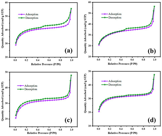
Figure 8.
BET isotherm of (a) MgO, (b) CrMg 1, (c) CrMg 3, and (d) CrMg 5 by IM method.
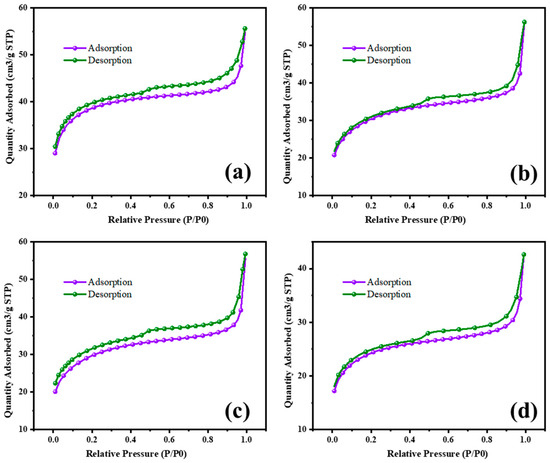
Figure 9.
BET isotherm of (a) MgO, (b) CrMg 1, (c) CrMg 3, and (d) CrMg 5 by AC method.
Comparisons with the literature data highlight that both MgO and CrMg 3 (AC) materials in this study exhibit relatively higher BET surface areas compared to previous reports. Notably, the preparation of CrMgX catalysts via the sol–gel auto-combustion route, as reported in this study, appears to be novel, as no prior studies have documented such preparations. This novel approach not only contributes to the scientific understanding of material synthesis but also underscores the potential for developing catalysts with enhanced textural properties. The overview of this study provides significant findings regarding the surface area characterization of MgO and CrMgX materials synthesized through different methods. The results not only underscore the influence of preparation techniques on material porosity but also establish a foundation for further exploration and optimization of catalysts for various industrial applications [29,30,31]. Future research may delve deeper into understanding the specific mechanisms underlying the observed textural properties and their implications for catalytic performance.
The sol–gel method allows for better control of the microstructure and particle size, stabilizing the mononuclear chromyl species. In addition, this method creates proper morphology with uniform coating and dispersion of chromium over MgO support.
4. Conclusions
Pure MgO and MgO-supported chromium oxide catalysts, CrMgX, were successfully synthesized from wet impregnation and sol–gel auto-combustion methods. Among the two methods, sol–gel auto-combustion was found to be suitable for synthesizing CrMgX catalysts. Moreover, the chromium loading of 3 wt% was found to be effective for both methods, as indicated by SEM images; the morphological study represents an improper surface for 1 wt% loading of chromia and agglomerated surface for 5 wt% loading of chromia, whereas 3 wt% loading of chromia created a uniform surface with complete coverage of chromia upon MgO. The sol–gel auto-combustion method was effective in creating MgO and CrMgX catalysts with a higher surface area. The surface area, as observed from the BET analysis, shows an enhanced surface area for CrMg 3 (AC) of about 115 m2 g−1 when compared with CrMg 3 (IM) (61 m2 g−1). This shows the effectiveness of the sol–gel auto-combustion method over wet-impregnation method. This reduced surface area of CrMgX (IM) relative to pure MgO (112 m2 g−1) is likely due to pore blockage by the chromia phase and the formation of the CrMg2O4 spinel. In contrast, CrMgX (AC) samples, synthesized through the sol–gel auto-combustion method, did not show spinel formation under identical conditions. Generally, the CrMgX (IM) samples demonstrated stronger interactions between the chromia and magnesia surfaces, leading to the stabilization of monochromate species on the surface. On the other hand, the CrMgX (AC) samples exhibited superior textural properties, along with a high surface area. These differences might be attributed to the variations in the chromia precursors used in each method. Further research is needed to fully understand the effects of impregnating Cr(NO3)2 onto MgO (AC). At higher chromium loading of 3 and 5 wt%, the CrMg 3 (AC) and CrMg 5 (AC) samples primarily stabilized polychromate species, whereas the CrMgX (IM) samples maintained monochromate stabilization. MgO-supported chromia catalysts prepared via the sol–gel auto-combustion method displayed robust textural and morphological properties, while those prepared by impregnation showed stronger oxide–oxide interactions. Modifying the sol–gel auto-combustion method by using Cr(NO3)2 instead of CrO3 could potentially enhance the surface, textural, and morphological properties, enabling the preparation of supported chromia catalysts with higher loadings without the undesirable formation of spinel structures.
Author Contributions
Conceptualization, T.P., S.P.A. and J.L.; methodology, S.P.A. and T.P.; software, S.P.A. and T.P.; validation, S.P.A., T.P. and J.L.; formal analysis, S.P.A. and T.P.; investigation, S.P.A. and T.P., resources, S.P.A.; data curation, S.P.A. and T.P.; writing—original draft preparation, S.P.A. and T.P.; writing—review and editing, S.P.A., T.P. and J.L.; visualization, S.P.A.; supervision, J.L.; project administration, J.L.; funding acquisition, J.L. All authors have read and agreed to the published version of the manuscript.
Funding
This research received no external funding.
Data Availability Statement
The original contributions presented in the study are included in the article, further inquiries can be directed to the corresponding author.
Conflicts of Interest
The authors declare no conflicts of interest.
References
- Aouani, H.; Wenger, J.; Gérard, D.; Rigneault, H.; Devaux, E.; Ebbesen, T.W.; Mahdavi, F.; Xu, T.; Blair, S. Crucial Role of the Adhesion Layer on the Plasmonic Fluorescence Enhancement. ACS Nano 2009, 3, 2043–2048. [Google Scholar] [CrossRef] [PubMed]
- Kurashige, W.; Kumazawa, R.; Ishii, D.; Hayashi, R.; Niihori, Y.; Hossain, S.; Nair, L.V.; Takayama, T.; Iwase, A.; Yamazoe, S.; et al. Au25-Loaded BaLa4Ti4O15 Water-Splitting Photocatalyst with Enhanced Activity and Durability Produced Using New Chromium Oxide Shell Formation Method. J. Phys. Chem. C 2018, 122, 13669–13681. [Google Scholar] [CrossRef]
- Ali, N.; Bashir, S.; Umm-i-Kalsoom; Begum, N.; Rafique, M.S.; Husinsky, W. Effect of Liquid Environment on the Titanium Surface Modification by Laser Ablation. Appl. Surf. Sci. 2017, 405, 298–307. [Google Scholar] [CrossRef]
- Zuñiga-Ibarra, V.A.; Shaji, S.; Krishnan, B.; Johny, J.; Sharma Kanakkillam, S.; Avellaneda, D.A.; Martinez, J.A.A.; Roy, T.K.D.; Ramos-Delgado, N.A. Synthesis and Characterization of Black TiO2 Nanoparticles by Pulsed Laser Irradiation in Liquid. Appl. Surf. Sci. 2019, 483, 156–164. [Google Scholar] [CrossRef]
- Riu, D.H.; Kong, Y.M.; Kim, H.E. Effect of Cr2O3 Addition on Microstructural Evolution and Mechanical Properties of Al2O3. J. Eur. Ceram. Soc. 2000, 20, 1475–1481. [Google Scholar] [CrossRef]
- Song, B.Y.; Zhang, X.F.; Huang, J.; Cheng, X.L.; Deng, Z.P.; Xu, Y.M.; Huo, L.H.; Gao, S. Porous Cr2O3 Architecture Assembled by Nano-Sized Cylinders/Ellipsoids for Enhanced Sensing to Trace H2S Gas. ACS Appl. Mater. Interfaces 2022, 14, 22302–22312. [Google Scholar] [CrossRef]
- Zhang, N.; Qian, Y.; Toyao, T.; Shimizu, K. Continuous Unsteady-State De-NOx System via Tandem Water–Gas Shift, NH3 Synthesis, and NH3–SCR under Periodic Lean/Rich Conditions. Environ. Sci. Technol. 2023, 57, 19584–19593. [Google Scholar] [CrossRef] [PubMed]
- Sartinska, L.L.; Barchikovski, S.; Wagenda, N.; Rud’, B.M.; Timofeeva, I.I. Laser Induced Modification of Surface Structures. Appl. Surf. Sci. 2007, 253, 4295–4299. [Google Scholar] [CrossRef]
- Yang, L.; Wang, Y.; Sui, C.; Liu, Z.; Liu, Y.; Li, Y.; Bai, J.; Liu, F.; Lu, G. Highly Selective and Humidity-Resistant Triethylamine Sensors Based on Pt and Cr2O3 Nanoparticles. ACS Appl. Nano Mater. 2022, 5, 15053–15061. [Google Scholar] [CrossRef]
- Vlasova, M.; Aguilar, P.A.M.; Kakazey, M.; Reséndiz-González, M.C.; Bykov, A.; Ragulya, A.; Tomila, T. Modification of a SiC-Cr5Si3 Ceramic Surface by Laser Irradiation. Ceram. Int. 2007, 33, 433–437. [Google Scholar] [CrossRef]
- Lodesani, A.; Picone, A.; Brambilla, A.; Giannotti, D.; Jagadeesh, M.S.; Calloni, A.; Bussetti, G.; Berti, G.; Zani, M.; Finazzi, M.; et al. Graphene as an Ideal Buffer Layer for the Growth of High-Quality Ultrathin Cr2O3 Layers on Ni(111). ACS Nano 2019, 13, 4361–4367. [Google Scholar] [CrossRef] [PubMed]
- Simeonidis, K.; Kalaitzidou, K.; Asimakidou, T.; Martinez-Boubeta, C.; Makridis, A.; Haeussler, A.; Vourlias, G.; Balcells, L. Tin Oxide Nanoparticles via Solar Vapor Deposition for Hexavalent Chromium Remediation. ACS Appl. Nano Mater. 2023, 6, 13902–13911. [Google Scholar] [CrossRef] [PubMed]
- Rittidech, A.; Portia, L.; Bongkarn, T. The Relationship between Microstructure and Mechanical Properties of Al2O3-MgO Ceramics. Mater. Sci. Eng. A 2006, 438–440, 395–398. [Google Scholar] [CrossRef]
- Biesinger, M.C.; Payne, B.P.; Grosvenor, A.P.; Lau, L.W.M.; Gerson, A.R.; Smart, R.S.C. Resolving Surface Chemical States in XPS Analysis of First Row Transition Metals, Oxides and Hydroxides: Cr, Mn, Fe, Co and Ni. Appl. Surf. Sci. 2011, 257, 2717–2730. [Google Scholar] [CrossRef]
- Pourdelan, H.; Alavi, S.M.; Rezaei, M.; Akbari, E.; Klyamkin, S. Production of Pure Hydrogen through Thermocatalytic Methane Decomposition Using NiO-MgO Catalysts Promoted by Chromium and Copper Prepared via Mechanochemical Method. Int. J. Energy Res. 2023, 2023, 5132640. [Google Scholar] [CrossRef]
- Zhang, H.; Wang, M.; Jia, Q.; Zhang, Z.; Lei, L.; Chen, L. Corrosion Mechanism of Reactive MgO-Bonded Cr2O3-Bearing Castables in CaO–Al2O3–Fe2O3–SiO2-Based Steel-Making Slag. J. Am. Ceram. Soc. 2024, 107, 1232–1248. [Google Scholar] [CrossRef]
- Choi, D.; Park, Y. Structural Modification of Salt-Promoted MgO Sorbents for Intermediate Temperature CO2 Capture. Nanoscale Adv. 2022, 4, 3083–3090. [Google Scholar] [CrossRef]
- Guzmán, K.d.C.M.; Shaji, S.; Das Roy, T.K.; Krishnan, B.; Avellaneda, D.A.; Aguilar Martinez, J.A.; Valdes, J.J.R. Surface Modification of Sintered Magnesium Oxide (MgO) with Chromium Oxide (Cr2O3) by Pulsed Laser Irradiation in Air and Liquids. Ceram. Int. 2021, 47, 21625–21632. [Google Scholar] [CrossRef]
- Hu, Y.; Guo, Y.; Sun, J.; Li, H.; Liu, W. Progress in MgO Sorbents for Cyclic CO2 Capture: A Comprehensive Review. J. Mater. Chem. A 2019, 7, 20103–20120. [Google Scholar] [CrossRef]
- Stolz, B.; Backes, G.; Gillner, A.; Kreutz, E.W. Selective Surface Modification of Ceramics with Laser Radiation. Appl. Surf. Sci. 1997, 109–110, 242–248. [Google Scholar] [CrossRef]
- García-Quiñonez, L.V.; Mendivil-Palma, M.I.; Roy, T.K.D.; Castillo-Rodríguez, G.A.; Gómez-Rodríguez, C.; Fernández-González, D.; Shaji, S. Effects of Irradiation Energy and Nanoparticle Concentrations on the Structure and Morphology of Laser Sintered Magnesia with Alumina and Iron Oxide Nanoparticles. Ceram. Int. 2020, 46, 7850–7860. [Google Scholar] [CrossRef]
- Xu, X.; Hu, S.; Pan, Q.; Huang, Y.; Zhang, J.; Chen, Y.; Wang, H.; Zheng, F.; Li, Q. Enhancing Structure Stability by Mg/Cr Co-Doped for High-Voltage Sodium-Ion Batteries. Small 2024, 20, 2307377. [Google Scholar] [CrossRef] [PubMed]
- Ouraipryvan, P.; Sreethawong, T.; Chavadej, S. Synthesis of Crystalline MgO Nanoparticle with Mesoporous-Assembled Structure via a Surfactant-Modified Sol-Gel Process. Mater. Lett. 2009, 63, 1862–1865. [Google Scholar] [CrossRef]
- Ding, J.; Ming, J.; Lu, D.; Wu, W.; Liu, M.; Zhao, X.; Li, C.; Yang, M.; Fang, P. Study of the Enhanced Visible-Light-Sensitive Photocatalytic Activity of Cr2O3-Loaded Titanate Nanosheets for Cr(VI) Degradation and H2 Generation. Catal. Sci. Technol. 2017, 7, 2283–2297. [Google Scholar] [CrossRef]
- Jan, F.; Zhi, S.; Sun, X.Y.; Li, B. Enhancing Catalytic Activity of Cr2O3 in CO2-Assisted Propane Dehydrogenation with Effective Dopant Engineering: A DFT-Based Microkinetic Simulation. Phys. Chem. Chem. Phys. 2024, 26, 9708–9721. [Google Scholar] [CrossRef]
- Lamberti, C.; Zecchina, A.; Groppo, E.; Bordiga, S. Probing the Surfaces of Heterogeneous Catalysts by in Situ IR Spectroscopy. Chem. Soc. Rev. 2010, 39, 4951–5001. [Google Scholar] [CrossRef] [PubMed]
- Mori, K.; Fujita, T.; Yamashita, H. Boosting the Activity of PdAg Alloy Nanoparticles during H2 Production from Formic Acid Induced by CrOx as an Inorganic Interface Modifier. EES Catal. 2023, 1, 84–93. [Google Scholar] [CrossRef]
- Mansoor, M.A.; Munawar, K.; Naeem, R.; Sarih, N.M.; Asghar, M.A.; Haider, A.; Zubir, M.N.M.; Zaharinie, T. Aerosol-Assisted Facile Fabrication of Bimetallic Cr2O3-Mn2O3 Thin Films for Photoelectrochemical Water Splitting. New J. Chem. 2023, 47, 8347–8354. [Google Scholar] [CrossRef]
- Bhateja, Y.; Ghosh, R.; Sponer, J.; Majumdar, S.; Cassone, G. A Cr2O3-Doped Graphene Sensor for Early Diagnosis of Liver Cirrhosis: A First-Principles Study. Phys. Chem. Chem. Phys. 2022, 24, 21372–21380. [Google Scholar] [CrossRef]
- Li, S.; Zhan, S.; Sun, J.; Yao, L.; Zhu, J.; Feng, J.; Xiong, Y.; Tian, S. Enhanced Ozonation of Pollutants by MgO Nanoclusters/Sewage Sludge-Derived Hierarchical Porous Carbon: Experimental and Theoretical Study. Environ. Sci. Nano 2021, 8, 2569–2583. [Google Scholar] [CrossRef]
- Herdiech, M.W.; Zhu, X.; Morales-Acosta, M.D.; Walker, F.J.; Altman, E.I. The Modification of Ferroelectric LiNbO3(0001) Surfaces Using Chromium Oxide Thin Films. Phys. Chem. Chem. Phys. 2015, 17, 9488–9498. [Google Scholar] [CrossRef] [PubMed]

Disclaimer/Publisher’s Note: The statements, opinions and data contained in all publications are solely those of the individual author(s) and contributor(s) and not of MDPI and/or the editor(s). MDPI and/or the editor(s) disclaim responsibility for any injury to people or property resulting from any ideas, methods, instructions or products referred to in the content. |
© 2024 by the authors. Licensee MDPI, Basel, Switzerland. This article is an open access article distributed under the terms and conditions of the Creative Commons Attribution (CC BY) license (https://creativecommons.org/licenses/by/4.0/).