Article

Design of Oil Mist and Volatile-Organic-Compound Treatment Equipment in the Manufacturing Plant

1
School of Mechanical Engineering, Guizhou University of Engineering Science, Bijie 551700, China
2
School of Electrical and Mechanical Engineering, Henan Institute of Science and Technology, Xinxiang 453000, China
3
School of Biological Engineering, Xinxiang University, Xinxiang 453000, China
4
Xinxiang Same Far Electric Co., Ltd., Xinxiang 453000, China
5
School of Mathematics and Statistics, Ningxia University, Yinchuan 750021, China
*
Author to whom correspondence should be addressed.
Processes 2024, 12(9), 2050; https://doi.org/10.3390/pr12092050
Submission received: 15 August 2024 / Revised: 15 September 2024 / Accepted: 21 September 2024 / Published: 23 September 2024
(This article belongs to the Special Issue New Research on Adsorbent Materials in Environmental Protection)

Abstract

:
To effectively confront the acute challenge of global warming, at the present stage, the Chinese government has designated carbon reduction as the core objective to accomplish the coordinated control of greenhouse gas and pollutant emissions. As China is a major manufacturing country, with the continuous improvement of air emission standards, it is particularly necessary to carry out the design of more efficient volatile organic pollutant emission devices. This study takes a treatment system with a waste gas ventilation volume of 6 × 10⁴ m3·h−1 as an example, adopts the end treatment approach of adsorption and catalytic combustion coupling, and designs a purification device composed of multistage oil-mist recovery, electrostatic adsorption, dry filtration, activated-carbon adsorption and desorption, catalytic combustion, etc. It also employs the fuzzy proportional-integral-derivative fine temperature control algorithm, and the temperature overshoot was decreased by 85%. The average emission concentration of volatile organic compounds at the equipment outlet is 6.56 mg·m−3, and the average removal rate is 93.99%, far surpassing the national emission standards. The device operates efficiently and stably, confirming that the end-coupled treatment system based on the adaptive fuzzy proportional-integral-derivative temperature control strategy can effectively handle volatile organic compounds with oil mist and holds significant promotion and research value.

1. Introduction

Volatile organic compounds (VOCs for brevity) are organic substances whose boiling points fall within the range of 50 to 260 °C at normal temperature. They chiefly encompass non-methane hydrocarbons (such as alkanes, alkenes, alkynes, and aromatic hydrocarbons), oxygen-containing organic compounds (such as aldehydes, ketones, alcohols, ethers, etc.), halogenated hydrocarbons, nitrogen- and sulfur-containing organic substances, and so on. These substances possess the traits of intense toxicity, pronounced pollution, and potent irritation [1,2,3,4]. In the manufacturing sector, within manufacturing workshops (such as paint spraying workshops and metal rolling workshops), during the operation of various production machinery and the production processes, a wide array of organic solvents, such as various lubricants, are extensively utilized. These organic solvents will generate VOCs with oil mist when exposed to high temperatures [5]. In recent years, the Chinese government has put forward numerous measures aimed at accelerating the synergy of “pollution reduction and carbon reduction” and the comprehensive rectification of VOCs to address environmental pollution. It is demanded to enhance the efficiency of equipment governance, guarantee that the total emissions of VOCs are reduced by more than 10% during the “14th Five-Year Plan” period, and fully wage the battle of environmental-pollution prevention and control [6,7,8]. Developed countries such as Europe and the United States are also actively exploring VOC-emission control strategies [9]. Currently, in the emission standards of the existing manufacturing industry in China, the removal rate of VOCs has risen from 70% to 80%, and even to 90% in some regions, which has presented arduous challenges to the design and development of treatment equipment [10].
To govern the VOCs accompanied by oil mist in manufacturing enterprises more efficaciously, efficient and non-secondary pollution terminal treatment modalities have emerged as the research emphasis [11,12]. The waste gas is predominantly addressed through the forms of recovery, destruction, and their combination [13,14]. Presently, substantial progress has been attained in the research of related technologies, such as membrane separation, condensation recovery, catalytic combustion, plasma treatment, and photocatalysis [15,16,17,18,19]. Nonetheless, during the actual process of treating VOCs with oil mist in the manufacturing sector, on account of the particularity of gas content, the treatment approaches need to deviate from those of VOCs in other industries. A solitary terminal treatment method is no longer competent to fulfill the requirements of standard discharge, presenting substantial challenges to the realization of standard discharge of VOCs for manufacturing enterprises. The principal problems lie herein: there exists a multiplicity of technical combination methods of recovery and destruction, and the matching degree with the types of VOCs with oil mist in manufacturing enterprises is inadequate; the temperature control accuracy of the destruction methods is subpar, and the temperature lag reaction gives rise to the insufficiency of timeliness in intermittent treatment, etc. [20,21].
Therefore, the design of the coupling treatment method and the refined temperature control hold extremely crucial engineering significance for the pollution-emission control of VOCs with oil mist in manufacturing enterprises, such as ultraviolet (UV) photolysis purification + activated-carbon adsorption, UV photolysis purification + solvent absorption, low-temperature plasma treatment + activated-carbon adsorption, etc. However, the treatment efficiencies of these combinations are relatively low (38%, 63%, and 60%, respectively), and the treated components are also comparatively scarce (33, 6, and 29, respectively) [22]. Consequently, multi-component and high-efficiency terminal coupling treatment methods require further exploration and research.
In manufacturing factories, the emissions of VOCs combined with oil mist demand separate treatment for both oil mist and VOCs. In recent years, within manufacturing enterprises, to achieve more effective removal of oil mist, a significant number of studies have proffered additional measures, primarily encompassing membrane separation, adsorption, and electrostatic deposition methods. Membrane separation is extensively utilized. Nonetheless, for fine oil mist, the treatment effectiveness is inadequate, and it is susceptible to causing membrane contamination. The key aspect of the adsorption method lies in the employment of specific adsorbents for adsorbing or dissolving oil mist particles, but it may potentially induce secondary pollution [23]. Electrostatic deposition entails charging the small molecule particles of oil mist under the influence of electric field force for collection. The effect is relatively pronounced; however, the surface of the separation structure will adhere to the oil mist, thereby reducing the removal efficiency [24]. Consequently, treating oil mist in exhaust gas constitutes a crucial and challenging endeavor.
A plethora of terminal treatment methods for VOCs exist, which can primarily be categorized into two major classes: recovery and destruction. The adsorption method within the recovery category is the most commonly utilized approach for treating industrial VOCs. Its equipment boasts a simplistic structure, high adsorption efficiency, and strong adaptability. The adsorption method not only enables effective collection and separation of VOCs but also permits the reuse of adsorption materials through thermal desorption or vacuum desorption. Nonetheless, if the adsorbent is mishandled, it is susceptible to causing secondary pollution [25]. The selection of the adsorbent constitutes the crux of the adsorption method, directly influencing the investment cost and safety. For this very reason, numerous researchers have focused their efforts on the development and optimization of adsorbents [26,27,28]. Catalytic combustion within the destruction category reduces the reaction activation energy using catalysts, facilitating the oxidation of VOCs into CO2, H2O, and other compounds with relatively lower hazardousness at a relatively low temperature (250~500 °C), thereby achieving the innocuous treatment of VOCs. This method enjoys the advantages of low energy consumption, high safety, a straightforward process operation, and the absence of secondary pollution. However, VOCs need to undergo pretreatment to attain the concentration requisite for combustion [29,30]. Currently, the catalysts in use are mainly classified as noble metal oxide catalysts, non-noble metal oxide catalysts, and composite metal catalysts [31,32]. Hence, the correct selection of adsorbents in the adsorption process and the judicious choice of catalysts in the catalytic combustion process are of utmost significance.
Fine-grained control and management of temperature can enhance the energy utilization rate and lower the operation costs, etc. Concerning the temperature control and management strategies in process control, researchers have formulated diverse controllers, such as proportional-integral (PI) control, proportional-integral-derivative (PID) control, and fuzzy control, to address the variations in conditions such as temperature, pressure, and liquid flow [33,34]. PID control features a simple structure, is convenient for operation, and exhibits strong robustness. Nevertheless, its control capability and accuracy are deficient. Especially for complex control objects, the control effect is unsatisfactory, and it relies on an accurate mathematical model. The fuzzy control method examines the system operation by utilizing if–then rules, and these rules have distinct degrees of matching under given operating conditions [35]. Fuzzy control is capable of handling ambiguous situations and generating solutions related to language variables. However, both PID control and fuzzy control encounter difficulties in responding to changes in operating conditions [36], which necessitates the development of superior controller models.
The aforementioned research findings primarily focused on the investigation of diverse terminal treatment modalities for VOCs and temperature control algorithms. The research team took the VOCs with oil mist with a total exhaust gas volume of 6 × 10⁴ m3·h−1 as an example and proposed a multistage oil-mist recovery + electrostatic adsorption + dry filtration + activated-carbon adsorption and desorption + catalytic combustion process. Combined with the fuzzy proportion-integration-derivative (PID) temperature control strategy and adopting the quantitative loading technology, the nano-precious-metal active components and various activating and stabilizing auxiliaries were loaded onto the honeycomb ceramics, enabling the oil mist and VOCs to undergo electrostatic adsorption for oil mist removal, dry filtration, activated-carbon adsorption and desorption, and catalytic combustion. Moreover, this method and device were applied to the copper tube production line of a certain company in China to deal with the large-flow and intermittent VOCs with oil mist existing in the company to verify the feasibility of the process, with the expectation of providing a reference for the emission treatment of VOCs with oil mist in manufacturing factories.

2. Materials and Methods

2.1. Design Scheme and Working Principle

The entire equipment is stipulated to possess a simplistic structure and be capable of accomplishing functions, such as high-efficiency dust elimination, oil removal, and purification. The gas after undergoing processing by this equipment is requisite to conform to relevant standards such as the “Emission Standard of Air Pollutants for Industrial Furnaces and Kilns” (DB41/1066-2020) [37] and the “Comprehensive Emission Standard of Air Pollutants” (GB16297-1996) [38] in China. This set of apparatuses is primarily composed of components, such as honeycomb electrostatic towers, activated-carbon boxes, catalytic combustion chambers, and ventilation ducts. The overall structure diagram is depicted in Figure 1. The process is mainly partitioned into the following steps.

2.1.1. Electrostatic Adsorption of Oil Mist

The exhaust gas is drawn into the multistage oil mist adsorber by the fan. Herein, the larger oil mist droplets and oil pollution particles are captured and collected due to mechanical collision and retention when passing through the spoiler. When the collected gas enters the high-voltage electrostatic field, under the effect of the high-voltage electric field, the oil mist gas is ionized and charged, with the majority of it being degraded and carbonized. A small number of minute oil particles move towards the positive and negative plates of the electric field under the concurrent action of the electric field force of the adsorption electric field and the airflow, are collected on the plates, and subsequently, flow to the oil collection tray under the influence of automatic gravity. Concurrently, under the action of the high-voltage generator, the ozone and hydroxyl radicals generated in the air within the electric field can effectively oxidize and decompose the organic pollutants in the exhaust gas, thereby reducing the concentrations of VOCs and ozone in the exhaust gas.

2.1.2. Activated-Carbon Adsorption

Following the preliminary treatments of dust removal, oil removal, and drying, the relatively pure organic waste gas enters the activated-carbon adsorption box for adsorption and purification processing. Organic substances are adsorbed within the micropores of the activated carbon, and the clean gas is discharged into the atmosphere via the chimney. After a certain period of adsorption, the activated carbon attains a saturated state. At this juncture, the organic matter has been concentrated within the activated carbon, and the adsorption ceases. Following the programmable logic controllers (PLC) automatic control program, the saturated activated-carbon box and the desorbed and standby activated-carbon box are alternately swapped. The fan conveys hot air into the activated-carbon box to raise the temperature of the carbon layer and, subsequently, “evaporates” the organic matter out of the activated carbon. The analyzed waste gas exhibits the characteristics of high concentration, small air volume, and high temperature. Catalytic combustion is employed for the desorption and regeneration of the saturated activated carbon for reutilization. The adsorption box adopts a multi-adsorption and one-desorption design for cyclic utilization.

2.1.3. Catalytic Combustion

The catalyst is utilized to oxidize and break down the combustible components in organic waste gas into CO2 and H2O at a relatively low temperature. This chemical reaction is represented as follows:
C n H m + ( n + m 4 ) O 2 n C O 2 + m 2 H 2 O + Q t
where CnHm is the volatile organic compounds containing hydrocarbon elements, and Qt is the release of a considerable amount of reaction heat.
The desorption procedure of the saturated honeycomb activated carbon is delineated as follows: Initiate the heating tubes and the desorption fan to enter the internal circulation stage. When the temperature of the hot gas source attains the boiling point of the organic matter, it infiltrates the activated-carbon box via the flame arrester, and the desorption operation of the activated-carbon box commences at this juncture. The organic waste gas characterized by high concentration and small air volume that is parsed out by the activated carbon enters the catalytic combustion chamber through the desorption pipeline. During the catalytic combustion process of the organic waste gas, it is decomposed into CO2 and H2O, and a substantial amount of heat is liberated. When the heat can reach the threshold where the organic waste gas undergoes spontaneous combustion, the heating unit is deactivated. After multiple cycles, the organic waste gas is comprehensively decomposed and discharged through the discharge pipeline to the chimney.

2.2. Critical Equipment Design

2.2.1. Cellular Electrostatic Tower

This unit is designed in line with the principle of electrostatic adsorption and mainly constitutes the equipment body, fire control system, automatic cleaning system, etc. The equipment body primarily encompasses the 304 stainless steel main frame, high-voltage generator, honeycomb tubes featuring the barb structure design, oil–water separator, and the like. The fire control system is capable of attaining the following: when the fire alarm probe detects the fire source or the system receives the fire alarm signal, the fire control system initiates instantaneously, the tower-type electrostatic discontinues power supply, and the fire pump operates, issues an alarm, and delays the shutdown of the fan. The automatic cleaning device can undertake regular automatic cleaning of the front filter screen, tower-type electrostatic unit, and other components along with the box body. It adopts a standard flange connection, and the equipment is upgradable. The main parameters are presented in Table 1.

2.2.2. Dry Filter Box

The dry filter box is a purification apparatus that segregates and captures solid and liquid particles within the gas through a porous filtering medium (filter material), and it adopts a box-frame structure fabricated from 45# steel. To preclude impurities such as dust in the treated gas from infiltrating the activated-carbon adsorption purification device system, a dry filter box is incorporated before the activated-carbon adsorption treatment to guarantee that the gas source cleanliness of the adsorption treatment system is ≥99% and the humidity is ≤80%.
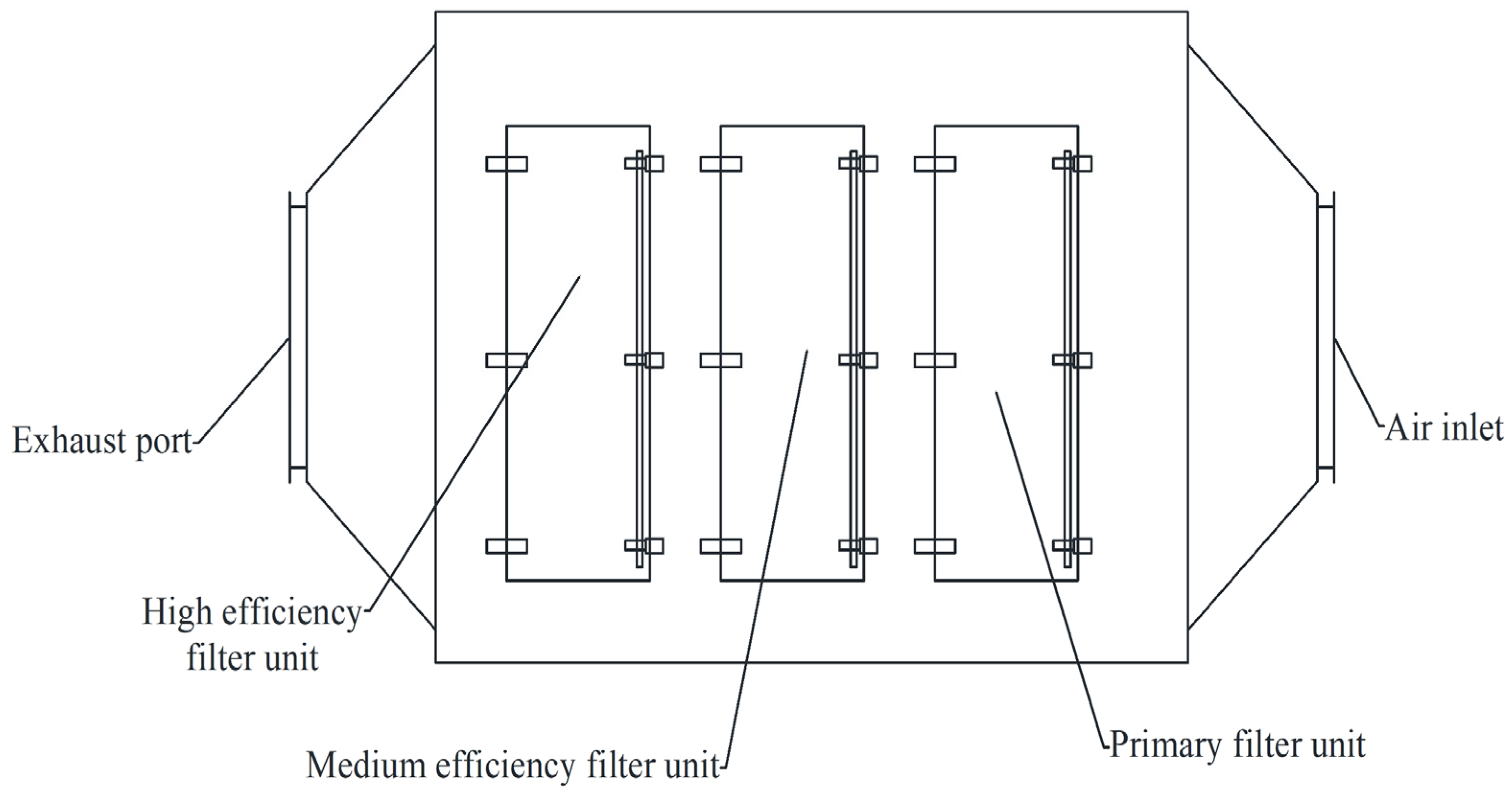
Figure 2 presents a schematic diagram of the structure of the dry filter box implementing a three-level treatment device. The filtration system adopts a modular design. Each level of the filter is outfitted with an access door for facilitating maintenance. The filter media are all composed of ultra-fine synthetic fibers incorporating electrostatic fibers, and the frames are all fabricated from G1401 aluminum alloy. The filter media and the frames are fixed through hot melt, augmenting the strength, airtightness, and bonding strength of the filter screen. The dry filter box is provisioned with a pressure gauge. When the pressure indicated by the filtration system exceeds a certain value, the control system will emit an alarm, and the operator is obligated to replace the filter media promptly. A differential pressure gauge (pointer type) is installed on the filtration section. When the differential pressure within the equipment surpasses the stipulated pressure, the filter cotton requires cleaning or replacement. After particles above 1 μm undergo filtration through the three levels of primary efficiency G4, medium efficiency F7, and high efficiency F9, the filtration efficiencies attain 45%, 85%, and 95%, respectively. The main parameters of the dry filter box are presented in Table 2.

2.2.3. Activated-Carbon Box

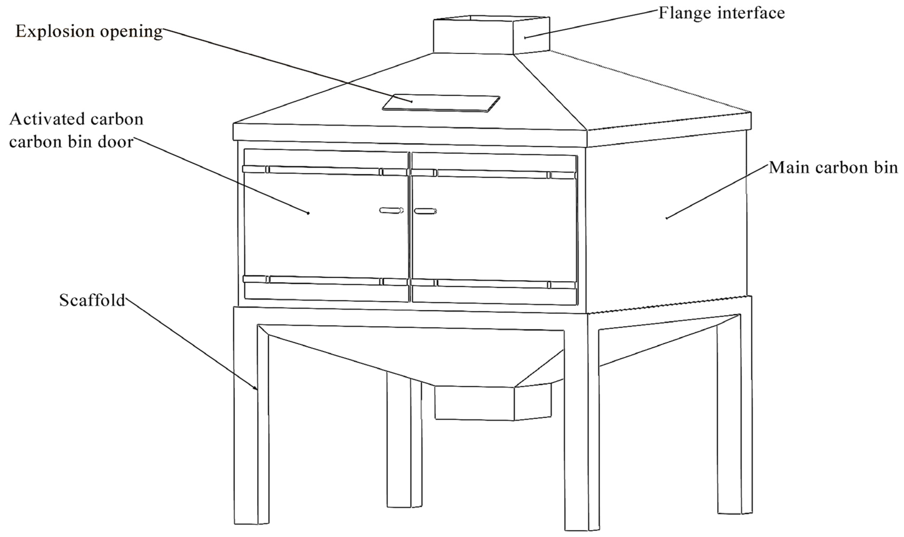
This component adopts the activated-carbon adsorption method for adsorption, the working mode is three adsorption and one desorption. The structure diagram is shown in Figure 3, and the structure is mainly composed of the main carbon bin, bracket, thermocouple, and spray.
The adsorption rate of activated carbon, the wind speed entering the activated-carbon box (the temporal span during which the gas interfaces with the activated carbon), and the quality of the activated carbon are salient indicators for the design [39]. It is discerned from the literature [40] that the gas flow rate impinges upon the time when the gas interfaces with the activated carbon and, thereby, exerts an influence on the adsorption effect. Scholarly studies have manifested that when employing honeycomb-shaped adsorbents for fixed adsorption, the gas flow rate ought to be lower than 1.2 m·s−1. This design is computed at 1.0 m·s−1. The size of the activated-carbon box is depicted in Table 3.
In terms of the safety design of the activated-carbon box. Firstly, the temperature within the main chamber of the activated-carbon box is monitored in real time, and a thermocouple (WRN-230K type) is utilized to monitor the temperature of the activated-carbon box. The temperature of the activated-carbon box must not exceed 40 °C during adsorption and 120 °C during desorption. Secondly, a water spray device is incorporated inside the activated-carbon box. When the temperature in the carbon bin rises abnormally, the electric control valve is opened under the control of the PLC for water spraying and cooling purposes.

2.2.4. Catalytic Combustion Chamber Design

The catalytic combustion chamber uses electric heat pipes, a catalyst, a thermocouple, a heat-exchange unit, an explosion-proof port, a high-temperature pressure fan, and a supplementary cooling fan. The detailed parameters can be found in Table 4.
(1)
Catalyst selection
The honeycomb ceramic composed of aluminosilicate is selected and coated with γ-Al2O3 as the carrier, and the high-performance catalyst (BH-300T/VOC) with precious metals Pt and Pd as the principal active components. When the temperature is approximately 250 °C and the space velocity is 20,000 h−1, the catalytic combustion efficiency of organic waste gas by this catalyst can attain 97%. This purification efficiency can comply with the requirements of relevant Chinese standards [41,42]. The carrier carrying the catalyst has a specification of 100 × 100 × 50 mm and is placed within the catalytic combustion chamber.
(2)
Heat-exchange unit
The designed desorption air volume is 2000 m3·h−1. The D25 × 2 × 800 mm 304 stainless steel pipes are used for heat-exchange arrangement, with a heat-exchange area of 25 m2. The calculation formula for the tubular heat transfer area is:
N = S π × D × L
where S is the heat transfer area, m2; D is the diameter of the heat-exchange tube, mm; L is the length of the heat-exchange tube, mm; N is the number of tubes, pcs.
(3)
Heating unit design
The designed desorption air volume is 2000 m3·h−1 and is expected to increase the temperature by 200 °C in 30 min. The specific heat capacity of the air is 1 kJ·(kg·°C)−1, and the air density is 1.293 kg·m−3. Therefore, the required power can be calculated as follows:
Q = C × M × ( t 0 t 1 ) 3600
where C is the specific heat capacity of the substance in the formula, kJ·(kg·°C)−1; M is the mass of the substance, kg; t 0 , t 1 stands for ambient temperature, °C.
Figure 4 depicts a schematic illustration of the structure of the catalytic combustion chamber. The temperature monitoring of the combustion chamber utilizes a distributed installation modality. Three thermocouples with a measurement range of 0~1200 °C are employed to measure the temperature within this zone, which is conducive to conserving electrical energy. Simultaneously, insulation cotton is affixed to the inner surface of the combustion chamber shell to diminish heat dissipation, and the explosion-proof valve positioned at the top offers a guarantee for the safety of the equipment.

2.3. Control System Design

Main System Control Flow

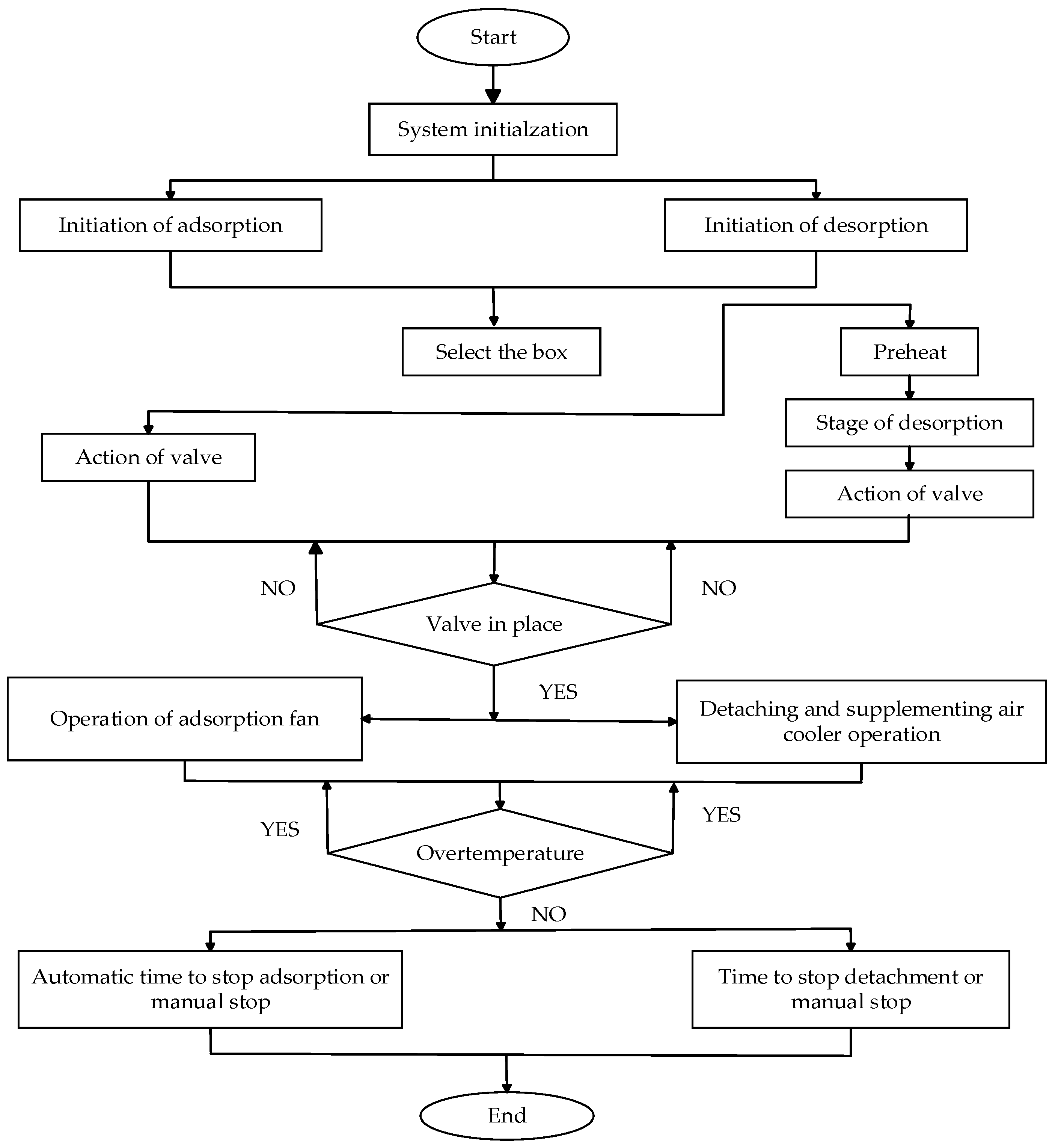
The schematic diagram of the program control flow is shown in Figure 5.
Upon the initiation of the system, the automatic initialization is performed initially. The startup program of the activated-carbon box is actuated, the activated-carbon box that requires opening is selected, and the valve position is examined to ascertain whether it is precisely executed. Subsequently, the fan is initiated, and the system enters the normal adsorption stage. Concurrently, the temperature of the entire system demands monitoring to avert abnormal (over-temperature) circumstances.
When the adsorption of the activated-carbon box attains saturation, the adsorption terminates. The adsorption valve is closed, the desorption valve is opened, and the activated-carbon box in the saturated state is preheated. When the desorption temperature is reached, the desorption fan and the cooling makeup fan commence operation and enter the normal desorption stage. The cessation of the desorption stage is categorized into two states: automatic and manual. When the desorption is accomplished, the desorption valve is closed, and the desorption fan and the cooling makeup fan are also deactivated. Hence, the work process concludes.

2.4. System Temperature Control Design

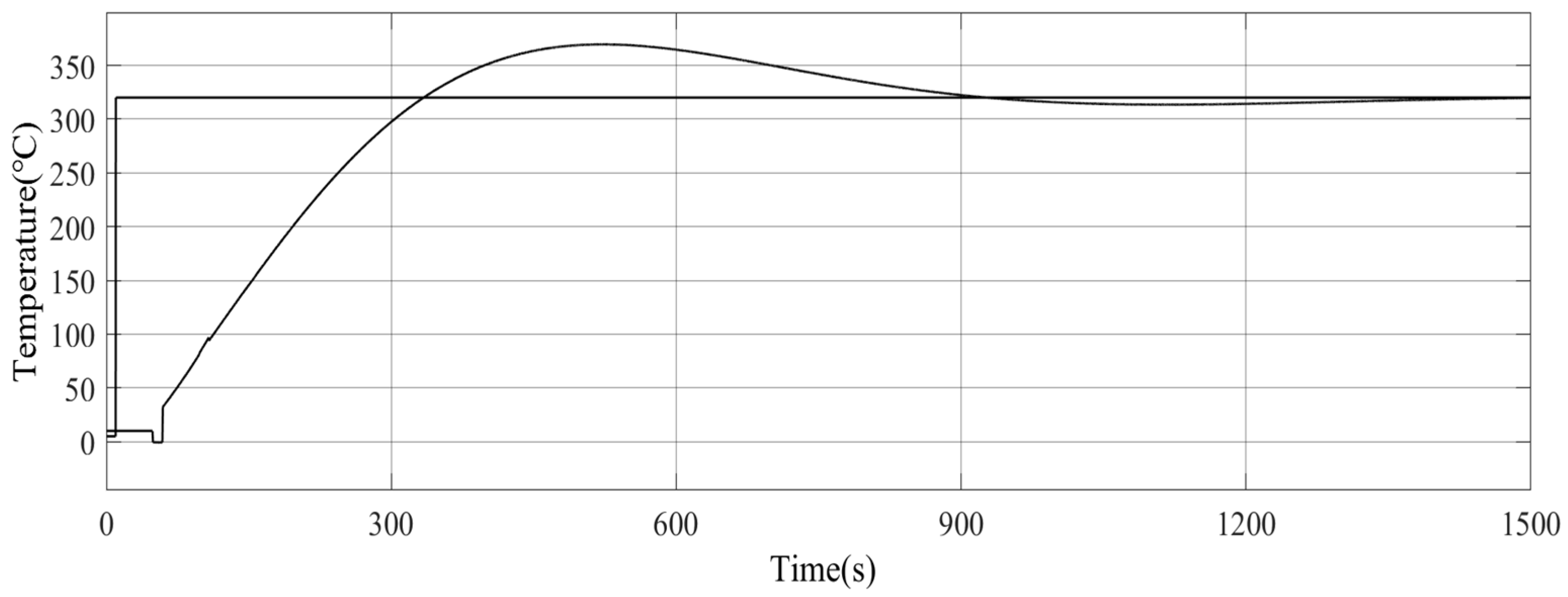
To facilitate real-time temperature monitoring and adjustment, this project aims to develop a temperature-adaptive control algorithm. The catalyst within the catalytic combustion chamber operates optimally at a standard temperature of 320 °C. When the actual temperature, as detected by the sensor, deviates from the set temperature, the system employs a fuzzy PID control algorithm to activate or deactivate the electric heater for effective temperature regulation.

2.4.1. Fuzzy PID Controller Design

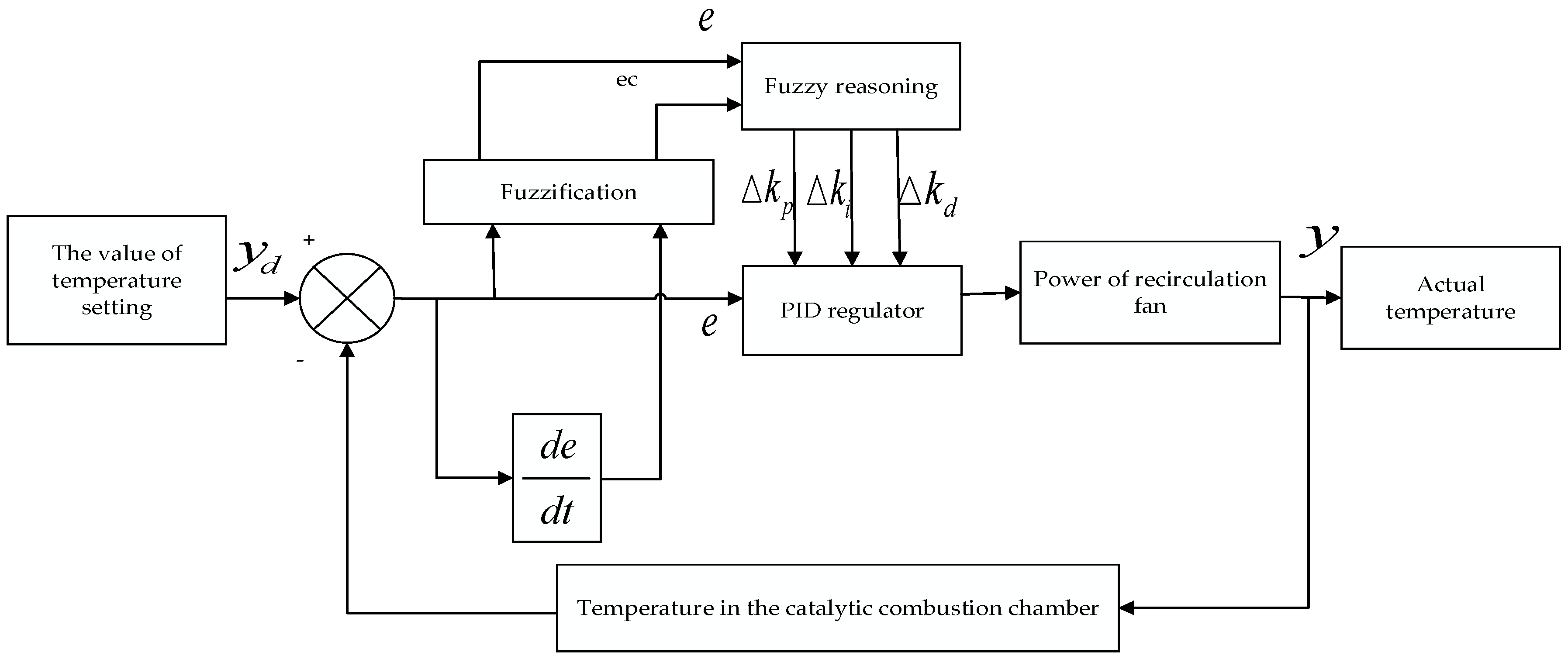
The logic principle of the fuzzy PID control algorithm is shown in Figure 6.
The fuzzy PID control algorithm performs real-time adjustment of the parameters of PID by specific fuzzy control rules, thereby overcoming the drawback that the parameters of traditional PID cannot be adjusted in real time [43]. Based on the temperature requirements within the catalytic combustion chamber in the system, the basic domains of the temperature deviation e and the temperature change rate ec of the combustion chamber are, respectively, determined to be {−6, 6} and {−3, 3}. After reasoning via fuzzy theory, the basic domains of the output proportional coefficient Vkp, integral coefficient Vki, and differential coefficient Vkd are, respectively, {0, 3}, {0, 3}, and {0, 100}. The fuzzy variable domain is set at 7 grades, and the corresponding fuzzy language variables are {NB, NM, NS, ZO, PS, PM, PB}, with the membership function adopting the trimf shape.
Based on extensive practical experience, fuzzy control rules are formulated to input into a fuzzy PID controller for systematic reasoning, thus enabling the determination of actual parameters for kp, ki, and kd for online tuning. The PID controller algorithm utilizes incremental calculation [44], with the following calculation method: k i = k i 0 + Δ k i , k p = k p 0 + Δ k p , k d = k d 0 + Δ k d .The proportional coefficient (kp0), integral coefficient (ki0), and differential coefficient (kd0) are assigned original values grounded in practical experience. The corresponding rules of the fuzzy control table are detailed in Table 5.

2.4.2. Mathematical Model of Temperature

The temperature within the catalytic combustion chamber is regulated using electric heating, and a first-order inertial lagging link is utilized to describe the mathematical model of the temperature environment [45,46,47], where its transfer function is:
G ( S ) = K e τ s T 0 + 1
where Κ is the proportional gain, denoting the extent of the self-balancing capacity of the catalytic combustion chamber. T0 is the pure lag time constant, embodying the inertia of heating inside the catalytic combustion chamber, precisely the capability of the catalytic combustion chamber to attain a new equilibrium state after being disrupted. τ is the pure lag constant.
During the heating and warming process of the catalytic combustion chamber, it is difficult to establish an idealized mathematical model of the combustion chamber due to the thermal conductivity of the internal workpieces and the change in airflow in the desorption process. In this paper, the two-point modeling method is used to determine the mathematical model of the temperature of the catalytic combustion chamber, given that the input step signal is 390 °C, and the temperature value is collected once every 120 s. The collected data are shown in Table 6.
The project used the two-point method to identify the parameters of the temperature transfer function [48,49]. The parameters of the transfer function were identified by sampling points (650, 0.4y (∞)) and (1491, 0.9y (∞)),the catalytic combustion chamber inputs were tested with a step signal, and the transfer function was:
U ( S ) = 320 S
It can be firmly established that the step response of its first-order inertial delay element is:
Y ( S ) = G ( S ) U ( S ) = 320 K e τ s s ( T 0 s + 1 )
The inverse Laplace change in Equation (6) gives the original function of time T0 as:
Y ( t ) = L 1 [ Y ( S ) ] = 320 K ( 1 e ( t τ ) T 0 )
Using the response steady-state values, the system gains can be found to be:
y ( ) = lim t y ( t ) = 320 K 1
Formula (8) gives K1 = 0.82
T = 1 L k = 1 L 2 ( t k + 1 t k ) , τ = 1 L k = 1 L = ( 2 t k t k + 1 )
According to mathematical Formula (9) in the literature [50], T = 238.5 and τ = 49.54 were obtained, and the two-point method was used to model the system. Thus, the model of the transfer function for heating the catalytic combustor was determined as follows:
G ( S ) = 0.82 e 49.54 s 238.5 s + 1

2.4.3. Traditional Control Algorithm

Employing the visualization simulation software Simulink within the software MATLAB (trial version of R2022a), the temperature structure diagram of the catalytic combustion chamber regulated by the PID algorithm is established. The temperature within the combustion chamber (T0) is selected as the control parameter. The three parameters of the PID controller in the temperature control system are, respectively: Kp = 1.2, Ki = 0.011, and Kd = 30. The simulation structure diagram based on the traditional PID control algorithm is illustrated in Figure 7, and the simulation analysis control curve is presented in Figure 8. The overshoot of the step function attains the maximum of 17.2% at approximately 520 s and descends to less than 2% at around 861 s. The traditional PID possesses the disadvantages of considerable overshoot and inadequate dynamic performance of the system in the temperature control model.

2.4.4. Fuzzy PID Control Algorithm

The fuzzy PID control algorithm for regulating the temperature of the catalytic combustion chamber is established via Simulink. The algorithm structure is presented in Figure 9, and the corresponding simulation analysis curve graph is illustrated in Figure 10. It can be inferred from the simulation model that the overshoot of the adaptive fuzzy control PID algorithm is merely 2.5%. The overshoot attains the maximum of 2% at approximately 190 s and becomes 0% after roughly 310 s. The overshoot of this approach is reduced by 85% compared to the traditional PID control algorithm. Through comparison, it is revealed that, although the traditional PID controller algorithm is straightforward and practical and holds good control effect and robustness, it is incapable of adjusting parameters online in line with the on-site circumstances. On the contrary, the fuzzy PID controller exhibits stronger adaptive capability, and its control accuracy, anti-interference ability, and robustness are more remarkable.

3. Results

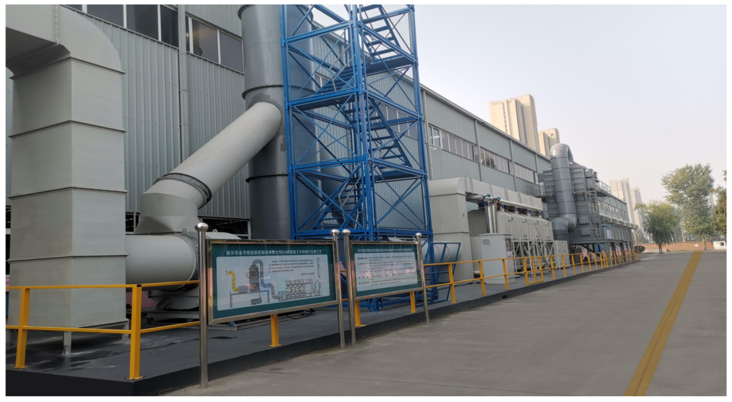
The verification of the device for the treatment of oil-mist VOCs based on the adsorption + catalytic combustion design methodology is carried out. The equipment is installed within Xinxiang Golden Dragon Precision Copper Tube Manufacturing Co., Ltd., in Xinxiang City, Henan Province, China. as illustrated in Figure 11. The relevant tests are executed by Henan Hengke Environmental Testing Co., Ltd. in Xinxiang City, Henan Province, China.

3.1. Testing Equipment

The emission gas of this set of equipment is collected by making use of the vacuum sampling box (manufactured by Qingdao Xin’ao Environmental Protection Technology Co., Ltd. in Qingdao City, Shandong Province, China.) and the various indicators of the gas are detected using the gas chromatograph (V5000) (from Changzhou Pannuo Instrument Co., Ltd. in Changzhou City, Jiangsu Province, China), the MH3300 gas and dust particle concentration tester (provided by Qingdao Minghua Electronic Instrument Co., Ltd. in Qingdao City, Shandong Province, China), and the TW-3200D low-concentration dust (gas) tester (supplied by Qingdao Tuowei Intelligent Instrument Co., Ltd. in Qingdao City, Shandong Province, China).

3.2. Test Standard

The exhaust gas is subjected to testing by the pertinent national standards [51,52], and the detection points are established based on the measurement technical requirements [53]. The detection points are, respectively, positioned at the inlet of the adsorption box pipeline and the exhaust gas outlet after the treatment by the catalytic combustion equipment, as depicted in Figure 1.
After the treatment of the exhaust gas, it is requisite to conform to the emission limits stipulated in the “Emission Standard of Air Pollutants for Industrial Furnaces and Kilns” DB41/1066-2020 [38] and the local “Notice on the Suggested Emission Values in the Special Governance Work of Volatile Organic Compounds in Industrial Enterprises in the Province” [54]; namely, the organized emission mass concentration of VOCs is less than 80 mg·m−3, and the removal rate of VOCs is greater than 70%. Some key industries mandate an effective removal rate of over 80% [55].
The treatment efficiency of VOCs ( η ) is given in Equation (11).
η = ( C i n C out ) C in × 100 %
where η is the removal rate of VOCs, %; Cin is the concentration at the air inlet of VOCs, mg·m−3; Cout is the outlet concentration of VOCs, mg·m−3.

3.3. Test Run Results

3.3.1. System Operation Test

This set of equipment entered the normal working state following a series of commissioning processes, encompassing parameters (such as temperature, fan speed, time, etc.), setting, line verification, single-point commissioning, continuous no-load, and load operation commissioning.
During the actual operation of the system, no faults or delays emerged in other related operations, such as the fan, heating control, and sensor data transmission display of the equipment. The actions of each valve were executed precisely, and there was no leakage at the main pipes, trunk pipes, or branch pipes themselves, as well as flange connections. The functions of the entire set of equipment operated impeccably. The results demonstrate that the design of this equipment is facile to operate, the method is practical and highly reliable, and it conforms to the actual requirements of the user enterprises.

3.3.2. System Operating Costs

After qualifying the overall operation of the equipment, the cost of the equipment includes the initial investment cost of the equipment of CNY 980,000, the annual operating cost of CNY 152,964.2, mainly including electricity, as well as the replacement cost of the filter cotton, the replacement cost of the activated carbon, and the replacement cost of the catalyst, as shown in Table 7.

3.3.3. VOC Treatment Effect

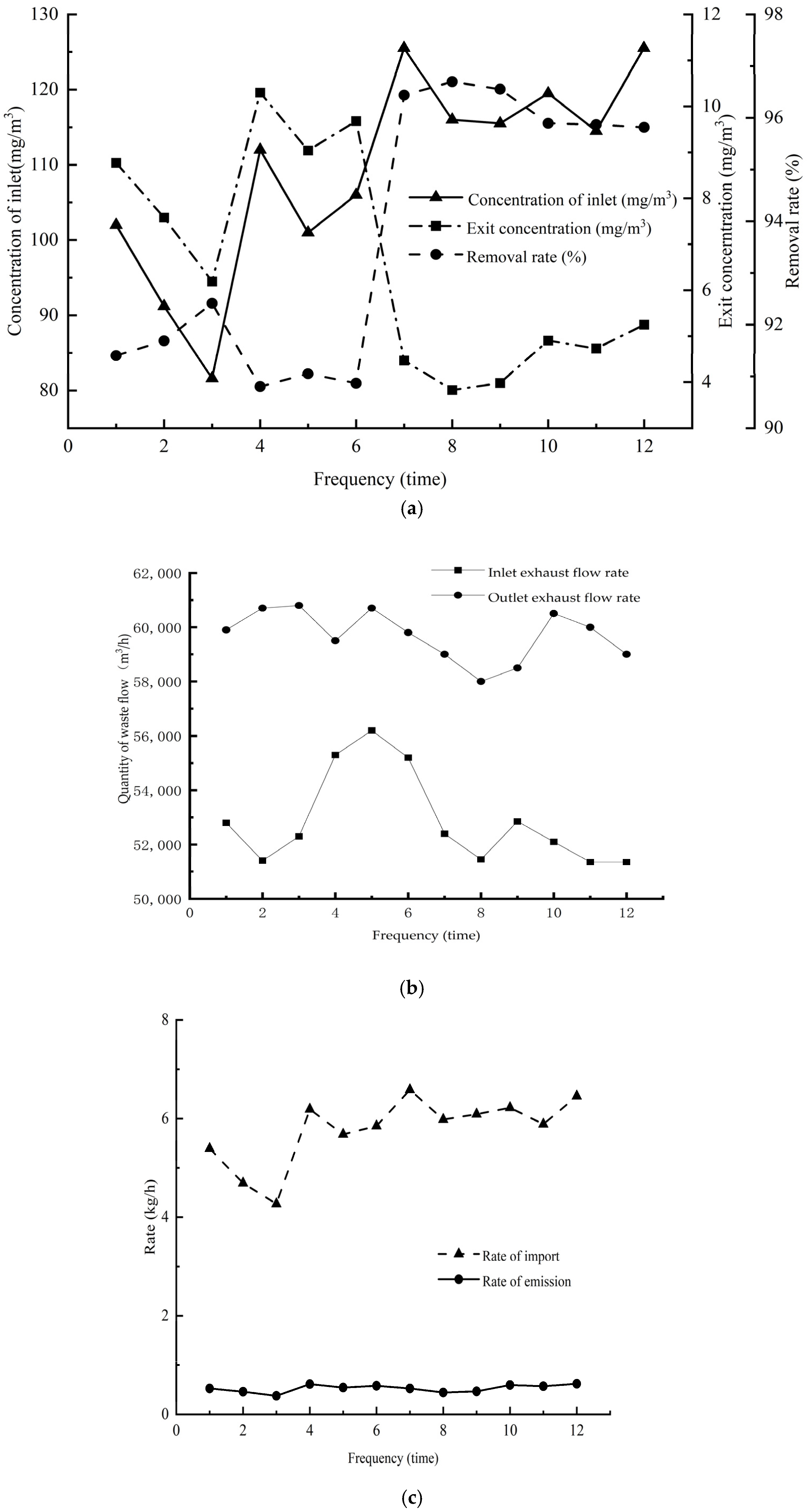
On the day of exhaust gas monitoring, the outdoor temperature fluctuated within the range of 5.2 °C to 8.3 °C, the air pressure stood at 101 kPa, and the wind speed was within the interval of 1.47 to 2.16 m·s−1. The initial emission mass concentration of the gas discharged from the online annealing process of copper tubes varied from 0 to 300 mg·m−3, and the exhaust gas flow rate fluctuated between 0 and 6 × 10⁴ m3·h−1. Once the equipment operated normally, the test results were recorded every three hours, and a total of 12 sets of test data were selected for analysis. The mass concentration, rate, and exhaust gas flow rate at the inlet and outlet during different periods were compared, and the outcomes are presented in Figure 12.
The flow rate at the inlet of the exhaust gas was within the range of 5.13 × 10⁴ to 5.62 × 10⁴ m3·h−1, and the outlet flow rate ranged from 5.8 × 10⁴ to 6.08 × 10⁴ m3·h−1. The flow rate at the outlet of the exhaust gas was profoundly influenced by the fluctuations of the inlet flow rate. The inlet mass concentration of the equipment ranged from 81.6 to 125.5 mg·m−3, and the outlet mass concentration was from 6.19 to 10.3 mg·m−3. The difference in the inlet mass concentration of the equipment was approximately 40 mg·m−3, and the difference in the outlet mass concentration was approximately 4 mg·m−3. The concentration change at the equipment’s outlet was relatively stable. It was computed that the rate of VOCs at the inlet of the equipment was from 4.27 to 6.46 kg·h−1, and the rate at the outlet was from 0.37 to 0.62 kg·h−1. The fluctuations in the emission rate were conspicuously affected by the fluctuations in the inlet rate and increased accordingly.

4. Discussion

4.1. Analysis of Processing Capacity and Processing Efficiency

In terms of processing capacity, the mass concentration of VOCs at the gas outlet is conspicuously lower than the emission limit of 80 mg·m−3. The fuzzy PID controller makes use of fuzzy logic and optimizes the PID parameters in real time by fuzzy rules, surmounting the deficiency that traditional PID parameters cannot be adjusted in real time. This set of equipment is competent to automatically regulate the heating tubes in the catalytic combustion chamber, maintaining the stable temperature of the combustion chamber, economically and efficiently addressing the stability issue of emission treatment caused by intermittent production cessation and enhancing the robustness of the exhaust gas treatment equipment.
In terms of processing efficiency, when the mass concentration of VOCs at the inlet ranges from 81.6 to 106 mg·m−3, the removal rate of VOCs varies from 90.80% to 92.41%. When the mass concentration of VOCs at the inlet ranges from 114.5 to 125.5 mg·m−3, the removal rate of VOCs ranges from 95.82% to 96.7%. Calculatedly, the comprehensive removal rate of VOC treatment exceeds 90%. Referring to the literature [56], when the concentration is below 89 mg·m−3, the removal rate is below 90%, but the removal rate of this experiment is all above 90%, which might be ascribed to the precise control of the temperature of the catalytic combustion chamber by the fuzzy PID controller. Additionally, the literature mentions that when the mass concentration reaches 1000 mg·m−3, the removal rate exceeds 98%. However, constrained by this project, such a high mass concentration was not attained, and the verification of this type of high mass concentration was not conducted. Meanwhile, the literature indicates that the higher the mass concentration, the more conducive it is to the improvement of the removal rate, which has been verified in this project. In conclusion, the treatment method based on adsorption + catalytic combustion is reasonable and practical, and the treatment is highly efficient and stable.

4.2. Innovation and Advantage

Table 8 consolidates the treatment efficacies of diverse VOC treatment technologies [22]. As can be discerned from Table 8, the average treatment efficiency of UV photolysis purification + activated-carbon adsorption can reach 38%, and among the 123 components of VOCs, the effectively treated ones amount to 33. The average treatment efficiency of direct combustion amounts to 85%, and the effective components treated are merely nine. The average treatment efficiency of activated-carbon adsorption + catalytic combustion is 90%, and the types of components that can be processed total 44. The average treatment efficiency of catalytic combustion is 78%, and the effective components treated come to 53 groups. Nevertheless, for single catalytic combustion, the exhaust gas necessitates pretreatment before catalytic combustion. The authors of [57,58] disclosed that the treatment efficiency of spray + low-temperature plasma for benzene, toluene, and xylene is approximately 75%, yet the treated components still demand further exploration. The authors of [55] stipulated that the VOC removal rate in key industries is not less than 80%, and some enterprises require it to be elevated to more than 90%. Hence, the treatment modality based on adsorption + catalytic combustion for processing VOCs holds substantial advantages.
Table 9 depicts the application scenarios of some currently predominant volatile-organic-compound (VOC) treatment technologies. Research findings suggest that activated-carbon adsorption–catalytic combustion technology is extensively employed in practice. Additionally, in some machining workshops, axial flow fans or high and low side fans are introduced to disperse the air above the workshop for the purpose of handling oil mist [59,60]. Although the air quality in the workshop has been improved to a certain extent, pollution still persists in the overall air content.
This study employs a multistage oil-mist recovery + honeycomb electrostatic adsorption + dry filtration + activated-carbon adsorption and desorption + catalytic combustion process to handle oil-mist-containing VOCs. The oil mist is addressed via the electrostatic adsorption tower, VOCs are adsorbed by the activated-carbon box, and desorption is executed after the activated-carbon box becomes saturated. The desorbed high-concentration VOCs are subsequently subjected to catalytic combustion treatment. The heat released by combustion can be utilized for air pretreatment or adsorbent desorption and recycling for energy conservation and environmental protection. This method has been verified on-site. The results demonstrate that the average removal rate of oil-mist-containing VOCs can attain 93.99%, the emission mass concentration is 6.56 mg·m−3, the treatment efficiency is high, the application scope is extensive, and there is no secondary pollution. Additionally, for industrial application scenarios, such as stretch forming machines, painting workshops, and CNC processing workshops with the same treatment air volume, it should be noted that there may be considerable differences in different industrial application scenarios, and some parameters of the system might need to be modified to ensure that the exhaust gas emissions after treatment comply with China’s emission requirements.
In the field of temperature control, the refined temperature control of equipment in process control is of paramount importance, as it can significantly affect key indicators, such as equipment removal rate and operating cost. The fuzzy PID control algorithm utilized in this study presents numerous advantages. Firstly, this algorithm is characterized by high control precision and can achieve accurate temperature control by dynamically adjusting parameters. Secondly, in response to temperature changes, this algorithm can respond rapidly, thereby effectively reducing fluctuation time. At the same time, it can automatically adjust parameters and exhibits excellent performance in anti-interference and noise suppression, firmly maintaining the stable state of the system. Additionally, this algorithm successfully combines the merits of fuzzy control and traditional PID control and is relatively easy to implement. It can be improved and optimized on the basis of the existing control system without the need for extensive transformation of the system, and its computational complexity is relatively low.

4.3. Environmentally Friendly Materials

The framework and casing of the entire equipment are composed of ASTM (American Society of Testing Materials) A283-C and 304 metal materials. The surface coating is required to utilize non-toxic water-based paint. All plastic components employ environmentally certified materials (such as polyethylene, PE). Catalysts, activated carbon, and filter materials all conform to environmental protection requirements. None of the components contain POPs (persistent organic pollutants) or volatile organic compounds (VOCs).

4.4. Application Prospects and Potential Challenges

The design approach of adsorption + catalytic combustion for the process of treating oil-mist-containing VOCs has been validated in enterprises. Presently, the designed processing air volume of the equipment amounts to 6 × 10⁴ m3·h−1. For various processing air volume demands, the number of certain equipment or the frequency of the fan can be adjusted in line with the actual situation to enhance the processing capacity of the equipment.
Moreover, considering that the emission concentration after the overall processing of the equipment is conspicuously lower than the emission limit, when multiple sets of equipment are operating in adjacent areas of the same factory zone, it can be contemplated to consolidate the chimneys of several sets of equipment into a single location, which can reduce the establishment of gas emission points and the input cost of the equipment. Additionally, the current equipment operation has not incorporated a digital twin system, precluding the prediction of failures in some parts of the equipment and the implementation of predictive maintenance. Personnel are obligated to conduct regular inspections. Concerning this issue, there are the following two solutions:
(1)
Optimize the control system of the equipment and integrate the management of the equipment with the Internet of Things to facilitate personnel to view it via the Internet of Things at any time.
(2)
Develop an APP mini-program to transfer the alarm records of the equipment to the mobile phones of relevant personnel in real time through the mini-program, enabling the prompt discovery and handling of equipment failures and ensuring the normal and stable operation of the equipment.

4.5. Balance and Traceability of Pollutants

The pollutants of the entire apparatus are primarily distributed in the following locations: the exhaust gas laden with oil mist discharged from the workshop is situated at the air inlet. After undergoing treatment by the electrostatic honeycomb tower, the waste oil is collected by the oil-receiving box. Additionally, pollutants are present at the filter cotton in the dry filter box, the activated carbon containing trace amounts of volatile organic compounds (VOCs) in the activated-carbon box, and the catalyst in the catalytic combustion chamber. The gas emitted from the chimney complies with the standards. The waste oil, waste activated carbon, and waste catalyst are stored separately and then transferred to units with corresponding recycling qualifications for recycling treatment, ensuring the absence of secondary pollution. Currently, in the treatment industry field, waste activated carbon is mainly processed by methods, such as combustion and microbial degradation. Given that the relevant technologies are relatively mature, this is not the focus of this paper.
The relevant data, such as wind speed flow, mass concentration, and rate of volatile organic compounds at the inlet and outlet of the equipment, were detected. After relevant calculations, it was found that the removal rate of the mass concentration of volatile organic compounds (VOCs) by the equipment can reach more than 99%, fully demonstrating the good balance of the equipment in dealing with pollutants.
In terms of traceability, in accordance with the relevant national regulations on pollutant discharge, the equipment must possess online display and data-recording functions and report online to the database platform of local and superior environmental protection departments. The system is equipped on site with multiple temperature sensors, buzzers, warning lights, and so on. By using a programmable logic controller (PLC) to collect data and with the assistance of configured program software, functions such as data management, historical data display and extraction, and parameter setting are realized. The equipment fully meets the mandatory requirements of relevant national regulations and has certain data analysis functions and automated management functions, thereby having data traceability. In addition, regarding the reversibility in the processing process of this device, the processing technologies employed in this paper are all mature processes and are not reversible. Due to space limitations, some conventional contents are not elaborated in the paper.

5. Conclusions

This study is dedicated to addressing volatile organic compounds (VOCs) accompanied by oil mist in production enterprises through the integrated design of activated-carbon adsorption and catalytic combustion as terminal treatment technologies. Taking the total waste gas volume containing oil-mist VOCs reaching 6 × 10⁴ m3·h−1 as an exemplification, a set of treatment processes encompassing multistage oil-mist recovery, electrostatic adsorption, dry filtration, activated-carbon adsorption and desorption, and catalytic combustion was introduced. Through the meticulous design of each process unit and the implementation of process verification within enterprises, the treated waste gas adhered to the emission standards. The overall commissioning and operation of the equipment were in an optimal state, and all functionalities met the stipulated requirements. Its characteristics are delineated as follows:
(1)
The coupled treatment of oil-mist VOCs generated during the production process of the enterprise was successfully achieved. The entire process not only retrieved and eliminated the oil mist but also executed adsorption and desorption as well as catalytic combustion treatment of VOCs. The gas at the inlet and outlet of the equipment was collected for detection, and the data, such as gas mass concentration, rate, and air volume, were analyzed and computed. The results manifested that the VOC emission mass concentration at the equipment outlet was 6.36 mg·m−3, and the average removal efficiency of the equipment treatment reached 93.99%, which was significantly higher than the 70% standard stipulated in China.
(2)
In the equipment control system, the fuzzy PID control algorithm was utilized to achieve precise temperature control. This algorithm exhibits certain advantages in terms of control accuracy, response time, and dynamic response. The temperature overshoot was reduced by 85%, which could curtail energy consumption and actively comply with China’s energy conservation and emission-reduction policies.
In summary, the combined design method of adsorption and catalysis can satisfy China’s emission requirements through the multistage treatment of oil-mist VOCs. Concurrently, the adoption of the fuzzy PID control strategy can mitigate equipment energy consumption, reduce certain economic expenditures, and augment the economic benefits of enterprises. The equipment operates efficiently and stably and meets the demands of the market. Due to the limited emission mass concentration of enterprises, the removal rate for mass concentrations higher than 300 mg·m−3 has not been verified, and this will be rectified in subsequent experiments. Additionally, remote control of the equipment constitutes a key focus for future research endeavors.

Author Contributions

Conceptualization, W.H., C.F. and H.Y.; methodology, W.H., C.F. and H.L.; software, W.H. and H.L.; validation, W.H., C.F., T.C. and M.Y.; formal analysis, W.H., Y.L. and C.F.; investigation, W.H. and H.Y.; resources, H.Y., Y.W. and C.F.; data curation, W.H., T.C. and Q.W.; writing—original draft preparation, W.H.; writing—review and editing, H.Y., C.F. and H.L.; visualization, W.H. and H.L.; supervision, Y.W., M.Y. and Q.W.; project administration, C.F. and H.Y.; funding acquisition, M.Y., Y.Z. and C.F. All authors have read and agreed to the published version of the manuscript.

Funding

This research was funded by Science and Technology Project of Henan Province (Grant No. 242102320150) and Joint Funds of the National Natural Science Foundation of China (Grant No. 52301205).

Data Availability Statement

Data for this study are available on request from the authors.

Acknowledgments

We express our profound gratitude to all the editors and experts who have made contributions and offered valuable suggestions for this article.

Conflicts of Interest

Author Ming Yu was employed by the company Xinxiang Same Far Electric Co., Ltd. The remaining authors declare that the research was conducted in the absence of any commercial or financial relationships that could be construed as a potential conflict of interest.

References

  1. Wu, X.Q.; Han, R.; Liu, Q.L.; Yun, S.; Lu, S.C.; Yang, L.Z.; Song, C.F.; Ji, N.; Ma, D.G.; Lu, X.B. A review of confined-structure catalysts in the catalytic oxidation of VOCs: Synthesis, characterization, and applications. Catal. Sci. Technol. 2021, 11, 5374–5387. [Google Scholar] [CrossRef]
  2. Buss, W.; Mašek, O.; Graham, M.; Wüst, D. Inherent organic compounds in biochar–their content, composition and potential toxic effects. J. Environ. Manag. 2015, 156, 150–157. [Google Scholar] [CrossRef] [PubMed]
  3. Niu, H.; Mo, Z.W.; Shao, M.; Lu, S.H.; Xie, S.D. Screening the emission sources of volatile organic compounds (VOCs) in China by multi-effects evaluation. Front. Environ. Sci. Eng. 2016, 10, 25–35. [Google Scholar] [CrossRef]
  4. Hussain, M.S.; Gupta, G.; Mishra, R.; Patel, N.; Gupta, S.; Alzarea, S.I.; Kazmi, I.; Kumbhar, P.; Disouza, J.; Dureja, H.; et al. Unlocking the secrets: Volatile organic compounds (VOCs) and their devastating effects on lung cancer. Pathol. Res. Pract. 2024, 255, 155157. [Google Scholar] [CrossRef]
  5. Zhong, M.F.; Li, Z.B.; Huang, H.M.; Ye, D.Q. Research on the emission characteristics and reduction potential of volatile organic compounds from industrial sources under the background of “Carbon Peak and Carbon Neutrality. Acta Sci. Circumst. 2022, 42, 12–25. [Google Scholar] [CrossRef]
  6. Mcdonald, B.C.; Gouw, J.A.D.; Gilman, J.B.; Jathar, S.H.; Akherati, A.; Cappa, C.D.; Jimenez, J.L.; Lee-taylor, J.; Hayes, P.L.; McKeen, S.A. Volatile chemical products emerging as largest petrochemical source of urban organic emissions. Science 2018, 359, 760–764. [Google Scholar] [CrossRef]
  7. The Central People’s Government of the People’s Republic of China, Further Lay The heavy Weather to Eliminate Pollution, Ozone Pollution Prevention and Diesel Cargo Vehicle Pollution Control Battle Action. Available online: https://www.gov.cn/zhengce/zhengceku/2022-11/17/content_5727605.htm (accessed on 10 November 2022).
  8. Ministry of Ecology and Environment of the People’s Republic of China, Ecological Environment in February Held a Regular Press Conference. Available online: https://www.mee.gov.cn/xxgk2018/xxgk/xxgk15/202102/t20210225_822424.html (accessed on 25 February 2021).
  9. Simon, H.; Hogrefe, C.; Whitehill, A.; Foley, K.M.; Liljegren, J.; Possiel, N.; Wells, B.; Henderson, B.H.; Valin, L.C.; Tonnesen, G.; et al. Revisiting day-of-week ozone patterns in an era of evolving US air quality. Atmos. Chem. Phys. 2024, 24, 1855–1871. [Google Scholar] [CrossRef]
  10. Liu, F.; Liu, W.; Long, Z.W.; Zhang, T.F. Evolution of particle size distribution and water content for oily particles in machining workshops. J. Build. 2024, 84, 108542. [Google Scholar] [CrossRef]
  11. Pui, W.K.; Yusoff, R.; Aroua, M.K. A review on activated carbon adsorption for volatile organic compounds (VOCs). Rev. Chem. Eng. 2019, 35, 649–668. [Google Scholar] [CrossRef]
  12. Li, K.; Luo, X. Research Progress on catalytic combustion of volatile organic compounds in industrial waste gas. Catalysts 2023, 13, 268. [Google Scholar] [CrossRef]
  13. Qu, M.M.; Cheng, Z.W.; Sun, Z.R.; Chen, D.Z.; Yu, J.M.; Chen, J.M. Non-thermal plasma coupled with catalysis for VOCs abatement: A review. Process Saf. Environ. Prot. 2021, 153, 139–158. [Google Scholar] [CrossRef]
  14. Tian, J.; Shi, Z.C.; Wan, Y.M.; He, H.X.; Li, T.; Ren, B.Z. Research progress of terminal treatment technology of volatile organic compounds. Appl. Chem. Ind. 2019, 48, 1433–1439. [Google Scholar] [CrossRef]
  15. Ozturk, B.; Kuru, C.; Aykac, H.; Kaya, S. VOC separation using immobilized liquid membranes impregnated with oils. Sep. Purif. Technol. 2015, 153, 1–6. [Google Scholar] [CrossRef]
  16. Zhang, X.L.; Ju, F.; Luan, H.; Xiu, G.L.; Ling, H. Dynamic adsorption behavior of light hydrocarbon VOCs on activated carbon. Environ. Prot. Chem. Ind. 2018, 38, 437–444. [Google Scholar]
  17. Mista, W.; Kacprzyk, R. Decomposition of toluene using non-thermal plasma reactor at room temperature. Catal. Today 2008, 137, 345–349. [Google Scholar] [CrossRef]
  18. Li, X.; Ma, J.; Ling, X. Design and dynamic behavior investigation of a novel VOC recovery system based on a deep condensation process. Cryogenics 2020, 107, 103060. [Google Scholar] [CrossRef]
  19. Yang, C.; Miao, G.; Pi, Y.H.; Xia, Q.B.; Wu, J.L.; Li, Z.; Xiao, J. Abatement of various types of VOCs by adsorption/catalytic oxidation: A review. Chem. Eng. J. 2019, 370, 1128–1153. [Google Scholar] [CrossRef]
  20. Zhao, H.M.; He, S.; Du, W.W.; Kong, X.Q.; Liu, Q.K. Common problems and countermeasures of VOCs exhaust gas terminal treatment measures in equipment manufacturing industry clusters. Mod. Chem. Ind. 2024, 44, 1–5. [Google Scholar]
  21. Liu, G. Practical Application of Activated Carbon Adsorption Concentration + Catalytic Combustion Technology. Chem. Eng. Manag. 2022, 2022, 99–101+125. [Google Scholar] [CrossRef]
  22. Ke, Y.T. Characteristics and control technology of volatile organic compounds emission from solvent use sources. South China Univ. Technol. 2020, 6, 9. [Google Scholar] [CrossRef]
  23. Zhou, L.J.; Xu, Z.Y. Ultralight, highly compressible, hydrophobic and anisotropic lamellar carbon aerogels from graphene/polyvinyl alcohol/cellulose nanofiber aerogel as oil removing absorbents. J. Hazard. 2020, 388, 121804. [Google Scholar] [CrossRef] [PubMed]
  24. Wu, H.; Yang, C.Z.; Dong, L.; Zhao, J. Discharge Characteristic of RS Barbed Electrodes in Wire-plate Electrostatic Precipitator in Air Environment. Energy Sci. Technol. 2020, 18, 42–48. [Google Scholar]
  25. Kujawa, J.; Zieba, M.; Zieba, W.; Al-gharabli, S.; Kujawski, W.; Terzyk, A.P. Hedgehog-like structure, PVDF-carbon nanohorn hybrid membranes for improved removal of VOCs from water. Chem. Eng. J. 2022, 438, 135574. [Google Scholar] [CrossRef]
  26. Li, D.; Chen, X.; Shu, C.Z.; Huang, Y.; Zhang, P.C.; Xiao, B.B.; Zhou, D. Ca-decorated MoBOH as a promising adsorbent for CH2O, C6H6, C3H6O, and C2HCl3 removal at room temperature: A first principle study. Appl. Surf. Sci. 2021, 563, 150233. [Google Scholar] [CrossRef]
  27. Wu, L.; Zhu, Y.; Yuan, J.; Guo, X.Z.; Zhang, Q.F. Advances in adsorption, absorption, and catalytic materials for VOCs generated in typical industries. Energies 2024, 17, 1861. [Google Scholar] [CrossRef]
  28. Liu, H.J.; Xu, B.W.; Wei, K.Y.; Yu, Y.S.; Long, C. Adsorption of low-concentration VOCs on various adsorbents: Correlating partition coefficient with surface energy of adsorbent. Sci. Total Environ. 2020, 733, 139376. [Google Scholar] [CrossRef]
  29. He, C.; Cheng, J.; Zhang, X.; Douthwaite, M.; Pattisson, S.; Hao, Z.P. Recent advances in the catalytic oxidation of volatile organic compounds: A review based on pollutant sorts and sources. Chem. Rev. 2019, 119, 4471–4568. [Google Scholar] [CrossRef]
  30. Chen, Z.; Li, J.; Cheng, Z.; Zuo, S.F. Well-defined and highly stable AlNi composite pillared clay supported PdOx nanocrystal catalysts for catalytic combustion of benzene. Appl. Clay Sci. 2018, 163, 227–234. [Google Scholar] [CrossRef]
  31. Kim, H.S.; Kim, H.J.; Kim, J.H.; Kim, J.H.; Kang, S.H.; Ryu, J.H.; Park, N.K.; Yun, D.S.; Bae, J.W. Noble-metal-based catalytic oxidation technology trends for volatile organic compound (VOC) removal. Catalysts 2022, 12, 63. [Google Scholar] [CrossRef]
  32. Kim, J.; Yu, J.L.; Lee, S.; A Tahmasebi, R.; Jeon, C.H.; Lucas, J. Advances in catalytic hydrogen combustion research: Catalysts, mechanism, kinetics, and reactor designs. Int. J. Hydrogen Energy 2021, 46, 40073–40104. [Google Scholar] [CrossRef]
  33. Deepa, S.; Anipriya, N.; Subbulakshmy, R. Design of controllers for continuous stirred tank reactor. IJPEDS Int. J. Power Electron. Drive Syst. 2015, 5, 576. [Google Scholar] [CrossRef]
  34. Arman, J.; Nader, N.; Jamali, A. Evolutionary design of marginally robust multivariable PID controller. Eng. Appl. Artif. Intel. 2023, 121, 105938. [Google Scholar] [CrossRef]
  35. Roy, K.; Mukherjee, A.; Jana, D.K. Prediction of maximum oil yield from almond seed in the chemical industry: A novel type-2 fuzzy logic approach. S. Afr. J. Chem. Eng. 2019, 29, 1–9. [Google Scholar] [CrossRef]
  36. Neugebauer, M.; Akdeniz, C.; Demir, V.; Yurdem, H. Fuzzy logic control for watering system. Sci. Rep. 2023, 13, 18485. [Google Scholar] [CrossRef] [PubMed]
  37. Ministry of Ecology and Environment of the People’s Republic of China. Notice on the Issuance of ‘Emission Standard of Air Pollutants for Industrial Kiln and Furnace’. Available online: https://www.mee.gov.cn/xxgk2018/xxgk/xxgk03/201907/t20190712_709309.html (accessed on 1 July 2019).
  38. Ministry of Ecology and Environment of the People’s Republic of China, ‘Integrated Emission Standard of Air Pollutants’ (GB3095-1966). Available online: https://www.mee.gov.cn/ywgz/fgbz/bz/bzwb/dqhjbh/dqgdwrywrwpfbz/199701/t19970101_67504.shtml (accessed on 1 January 1997).
  39. Egedy, A.; Gyurik, L.; Ulbert, Z.; Rado, A. CFD modeling and environmental assessment of a VOC removal silo. Int. J. Environ. Sci. Technol. 2021, 18, 141–150. [Google Scholar] [CrossRef]
  40. Ministry of Ecology and Environment of the Peoples’s Republic of China, Technical Specifications of Adsorption Method for Industrial Organic Emissions Treatment Project (Ecological Environment Standard HJ 2026-2013). Available online: https://www.mee.gov.cn/ywgz/fgbz/bz/bzwb/other/hjbhgc/201304/t20130403_250331.htm (accessed on 1 July 2013).
  41. Huangfu, C.Y.; Yao, L.L.; Ma, Y.Y.; Guo, S.S.; Wang, Z.T.; Wu, S.C.; Jin, K.; Jiang, X.Y.; Zhao, W.R. Influence of application scenarios on the performance of noble metal catalysts for catalytic combustion. Environ. Poll. Control. 2023, 45, 1047–1054. [Google Scholar] [CrossRef]
  42. Huang, L. Research on the joint application of ‘activated carbon adsorption catalytic combustion’ process in VOCs treatment. Mod. Chem. Res. 2023, 2023, 167–169. [Google Scholar] [CrossRef]
  43. Chu, C.W.; Zhu, Z.C.; Bian, H.T.; Jiang, J.C. Design of self-heating test platform for sulfide corrosion and oxidation based on fuzzy PID temperature control system. Meas. Control. 2021, 54, 1082–1096. [Google Scholar] [CrossRef]
  44. Wang, Z.H.; Zhang, J. Incremental PID controller-based learning rate scheduler for stochastic gradient descent. IEEE Trans. Neural Netw. Learn. Syst. 2024, 35, 7060–7071. [Google Scholar] [CrossRef]
  45. Yang, K.L.; Xu, Y.Y. Research on PID control optimization simulation of humanoid robot. Chin. J. Constr. Mach. 2022, 20, 542–546. [Google Scholar] [CrossRef]
  46. Zhang, S.Y.; Ma, T.B.; Luo, S.S.; Wang, C. Based on the fuzzy adaptive PID temperature control in vacuum chamber study. Autom. Manuf. Technol. 2019, 11, 92–95. [Google Scholar] [CrossRef]
  47. Hashemi, E.M.; Gelin, P.; Maisto, A.; Gardeniers, H.; Malsche, W.D. Enhanced performance of an acoustofluidic device by integrating temperature control. Micromachines 2024, 15, 191. [Google Scholar] [CrossRef] [PubMed]
  48. Gao, L.T.; Dai, S.H.; Xu, X.M.; Zhou, J.; Li, M. Greenhouse temperature and humidity coupling control method research. J. Agric. Mech. Res. 2021, 43, 2430. [Google Scholar] [CrossRef]
  49. Liu, H. The heating furnace control system is based on an adaptive fuzzy PID design. Autom. Appl. 2024, 65, 91–94. [Google Scholar] [CrossRef]
  50. Ding, F.; Xu, L.; Liu, X.M. Transfer function identification (1): Step response two-point method and three-point method. Qingdao Univ. Sci. Technol. 2018, 39, 1–14. [Google Scholar] [CrossRef]
  51. Ministry of Ecology and Environment of the People’s Republic of China, Stationary Source Emission-Determination of Total Hydrocarbons, Methane and Nonmethane Hydrocarbons Gas Chromatography. Available online: https://www.mee.gov.cn/ywgz/fgbz/bz/bzwb/jcffbz/201801/t20180108_429313.shtml (accessed on 1 April 2018).
  52. Ministry of Ecology and Environment of the People’s Republic of China, Specifications for Continuous Emissions Monitoring of SO2, NOX, and Particulate Matter in the Flue Gas Emitted from Stationary Sources (HJ 75-2017). Available online: https://www.mee.gov.cn/ywgz/fgbz/bz/bzwb/jcffbz/201801/t20180108_429327.shtml (accessed on 1 March 2018).
  53. Ministry of Ecology and Environment of the People’s Republic of China, Technical Specifications for Emission Monitoring of Stationary Source. Available online: https://www.mee.gov.cn/ywgz/fgbz/bz/bzwb/jcffbz/200712/t20071213_114278.htm (accessed on 1 March 2018).
  54. Henan Provincial Environmental Pollution Prevention and Control Leading Group Office of the People’s Republic of China, Notice on the Recommended Emission Value in the Special Treatment of Volatile Organic Compounds in Industrial Enterprises in the Province. Available online: https://www.doc88.com/p-71847759631018.html (accessed on 2 June 2017).
  55. Ministry of Ecology and Environment of the People’s Republic of China, Notice on the issuance of the Comprehensive Treatment Plan for Volatile Organic Compounds in Key Industries. Available online: https://www.mee.gov.cn/xxgk2018/xxgk/xxgk03/201907/t20190703_708395.html (accessed on 26 June 2019).
  56. Lu, P.W.; Liu, Z.P.; Li, D.G.; Sun, Q.L.; Zhao, S.P.; Chen, L.J. Treatment and application of multi-effect heat recovery catalytic combustion process to intermittent VOCs in pharmaceutical enterprises. Chin. J. Environ. Eng. 2023, 17, 1274–1282. [Google Scholar] [CrossRef]
  57. Zhu, L.H. Treatment of simulated waste gas from painting by micro-nano bubble spray and low-temperature plasma. Yangzhou Univ. 2020, 6, 11. [Google Scholar] [CrossRef]
  58. Chang, Z.; Wang, C.; Zhang, G. Progress in degradation of volatile organic compounds based on low-temperature plasma technology. Plasma Process. Polym. 2020, 17, 900131. [Google Scholar] [CrossRef]
  59. Li, Y.L.; Zong, S.J.; Jing, H.W.; Gao, N.; Ye, H.P.; Chen, J.B. The influence of ventilation modes on oil mist particles diffusion in a machining workshop. Heliyon 2024, 10, e26963. [Google Scholar] [CrossRef]
  60. Yang, Y.; Chen, H.; Cao, Q.F.; Qiao, M.D.; Wang, Y.; Fan, J.N.; Yang, C.H.; Pan, B.; Wang, X.; Wang, F.; et al. Purification technology of oil mist in industrial buildings: A review. Build. Environ. 2023, 235, 110229. [Google Scholar] [CrossRef]
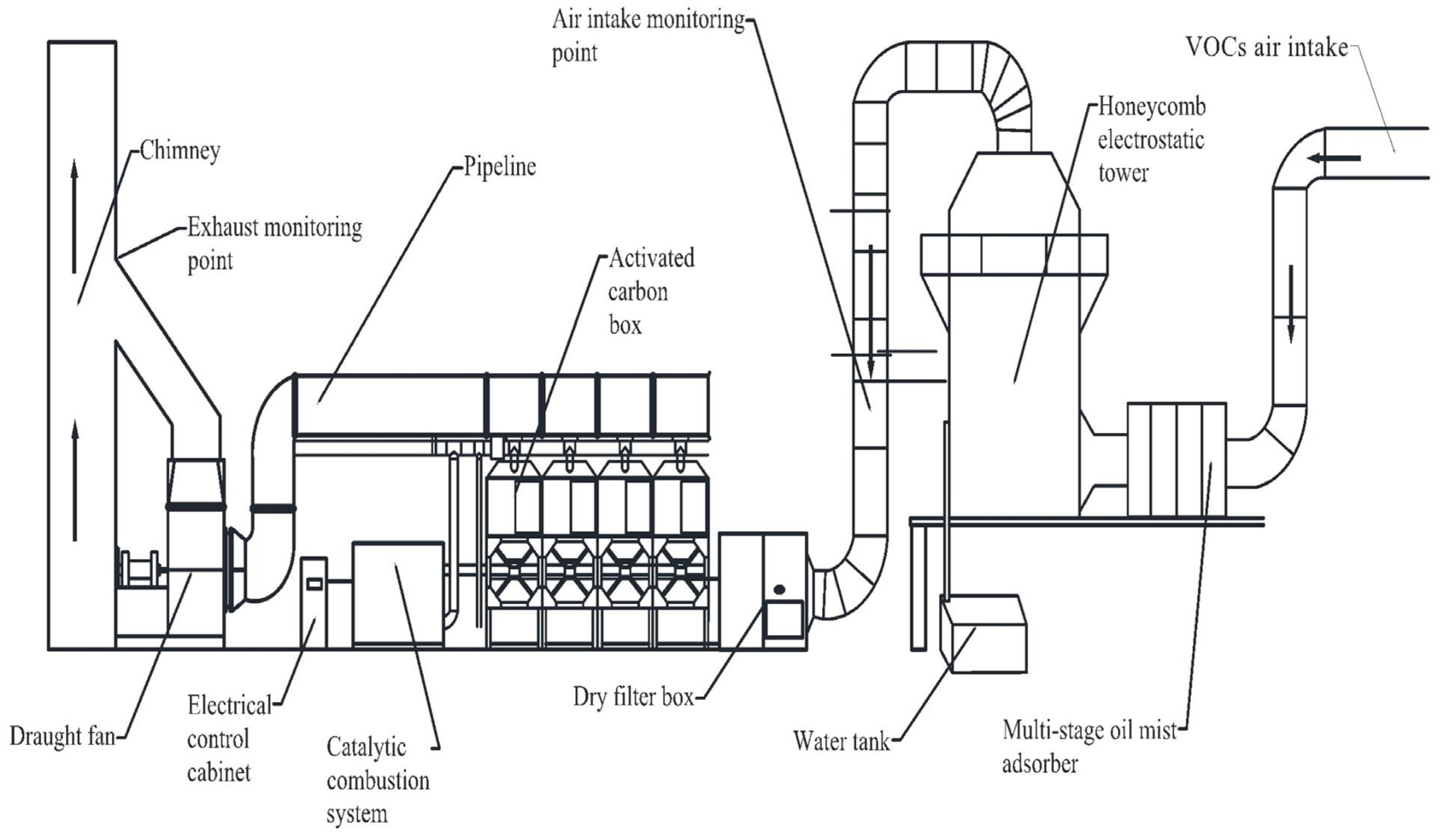
Figure 1. Overall structure diagram.
Processes 12 02050 g001
Figure 2. Schematic diagram of dry filter box.
Processes 12 02050 g002
Figure 3. Structure diagram of activated-carbon box.
Processes 12 02050 g003
Figure 4. Schematic diagram of the catalytic combustion chamber structure.
Processes 12 02050 g004
Figure 5. Schematic diagram of the program control flow.
Processes 12 02050 g005
Figure 6. Logic schematic diagram based on fuzzy PID control scheme.
Processes 12 02050 g006
Figure 7. Schematic diagram of the PID simulation structure.
Processes 12 02050 g007
Figure 8. Response curve of PID control system.
Processes 12 02050 g008
Figure 9. Fuzzy PID control system frame diagram.
Processes 12 02050 g009
Figure 10. Response curve of fuzzy PID system.
Processes 12 02050 g010
Figure 11. Equipment installation site.
Processes 12 02050 g011
Figure 12. Gas detection result: (a) comparison of VOCs concentration, (b) air volume comparison diagram, (c) VOCs rate comparison diagram.
Processes 12 02050 g012
Table 1. Main parameters of the adsorption unit.
Designation ItemParameterUnits
High-voltage generator maximum power20kW
Honeycomb tube sizeΦ159 × 4000mm
Number of honeycomb tubes in the power plant280pcs
Table 2. Main equipment parameters of TY-GL-20K dry filter box.
Designation ItemParameterUnits
G4 initial filter resistance<85Pa
F7 medium filter resistance<100Pa
F9 high-efficiency tilter resistance<130Pa
Equipment wall thickness2mm
Table 3. Main parameters of activated-carbon box.
Designation ItemParameterUnits
Air volume20,000m3·h−1
Activated-carbon box size (single)2000 × 2000 × 2600mm
Single activated-carbon fiber filling amount150kg
Table 4. Main parameters of catalytic combustion equipment.
SectionDesignation ItemParameterUnits
Heat
exchange
unit
Material and thicknessQ235A cold-rolling sheet steel (t = 2.0)mm
Heat transfer area25m2
Number of heat-exchanger tubes420pcs
Electric heating unitCabinet600 × 800 × 690mm
Power72kW
Amount36pcs
OtherBoundary dimension1500 × 900 × 1500mm
Outline borderQ235 sheet steel (t = 3)mm
FaceplateQ235 sheet steel (t = 1.5)mm
Table 5. Fuzzy rule control table.
ece
NBNMNSZOPSPMPB
NBPB/NB/PSPB/NB/NSPM/NM/NBPM/NM/NBPS/NS/NBZO/ZO/NMZO/ZO/PS
NMPB/NB/PSPB/NB/NSPM/NM/NBPS/NS/NMPS/NS/NMZO/ZO/NSNS/ZO/ZO
NSPM/NB/ZOPM/NM/NSPM/NS/NMPS/NS/NMZO/ZO/NSNS/PS/NSNS/PS/ZO
ZOPM/NM/ZOPM/NM/NSPS/NS/NSZO/ZO/NSNS/PS/NSNM/PM/NSNM/PM/ZO
PSPS/NM/ZOPS/NS/ZOZO/ZO/ZONS/PS/ZONS/PS/ZONM/PM/ZONM/PB/ZO
PMPS/ZO/PBZO/ZO/NSNS/PS/PSNM/PS/PSNM/PB/PSNM/PB/PSNB/PB/PB
PBZO/ZO/PBNS/ZO/PMNS/PS/PMNM/PM/PMNM/PB/PMNB/PB/PBNB/PB/PB
Table 6. Temperature acquisition data.
Numerical OrderTime
(s)
Temperature
(°C)
Numerical OrderTime
(s)
Temperature
(°C)
1059960183.30
212027.53101080205.28
324049.99111200227.18
436072.38121320249.02
548094.71131440270.79
6600116.96141560292.49
7720139.14151680314.13
8840161.26161800335.69
Table 7. Main costs of the year operation.
Designation ItemParameterAnnual Operating Expenses (CNY)Comment
Cost of replacement of filter cotton40 m29600Replace every 30 days, 12 times per year, the unit price is 20 CNY/m2
Electricity charge of system fan40 kW96,000Working hours are 10 h/day, 300 days/year
Desorption fan2.5 kW2064Working hours are 6 h/day, 172 times/year
Cost of replacement of activated carbon4.6 m319,0089600 CNY/m3 to replace once/3 years
Catalytic bed72 kW16,842.2The working time is 4 h/time, 43 times/box/year 4 boxes
Catalyst0.15 m39450210,000 CNY/m3 to replace once/3 years
Total annual cost 152,964.2
Table 8. Comparison of different VOC treatment technologies.
Technical NameGovernance Efficiency RangeGovernance Efficiency AverageNumber of Governance Components
Activated-carbon adsorption−182~86%31%33
Direct combustion85%85%9
Catalytic combustion50~93%78%53
UV photolysis purification34~53%44%18
Activated-carbon adsorption + catalytic combustion85~97%90%44
Low-temperature plasma + activated carbon27~81%60%29
UV light purification + activated-carbon adsorption−24~76%38%33
UV light purification + solvent adsorption25~87%63%6
Note: Due to the position of the adsorption box, it will be subjected to high temperature, resulting in desorption, so the measurement value will be negative.
Table 9. Comparison of the application of different treatment techniques.
Technical NameApplicable Concentration (mg·h−1)Core EquipmentMerit and Demerit
Activated-carbon adsorption2000–10,000Adsorption bedThe adsorption range is wide, and the treatment degree is controllable. It is difficult to regenerate and easy to produce secondary pollution
Direct combustion3000–1/4LELIncineratorHigh-efficiency, simple maintenance; the processing temperature is high, the fuel cost is high, and the equipment cost is high
Catalytic combustion1000–1/4LELCatalytic combustorWide application range, high purification efficiency, no secondary pollution; the catalyst is toxic and needs pretreatment
UV photolysis purification<500Photodissociation catalytic reactorChemicals are not required, but the reaction rate is slow
Low-temperature plasma<500Plasma reactorRequires high-pressure equipment, covers a large area, but the reaction rate is faster
Low-temperature plasma–UV light purification20–1000Plasma reactor, photodissociation catalytic reactorLow energy consumption, fewer by-products, fast reaction rate; the mechanism is complex and needs further study
UV light purification + activated-carbon adsorption200–2000Adsorption bed, photodissociation catalytic reactorSmall footprint, mild reaction conditions, low energy consumption, high safety; it is greatly affected by gas flow
Activated-carbon adsorption + catalytic combustion300–1000Adsorption bed, catalytic combustorWide range of application, good economic benefits, no secondary pollution, energy saving, and environmental protection; the process conditions are strict, and the safety is limited
Note: LEL is the lower explosive limit for VOC components.
Disclaimer/Publisher’s Note: The statements, opinions and data contained in all publications are solely those of the individual author(s) and contributor(s) and not of MDPI and/or the editor(s). MDPI and/or the editor(s) disclaim responsibility for any injury to people or property resulting from any ideas, methods, instructions or products referred to in the content.