Article

Numerical Study to Optimize the Operating Parameters of a Real-Sized Industrial-Scale Micron Air Classifier Used for Manufacturing Fine Quartz Powder and a Comparison with the Prototype Model

by
Nang Xuan Ho
1,*,
Hoi Thi Dinh
1,2,* and
Nhu The Dau
2
1
Faculty of Vehicle and Energy Engineering, Phenikaa University, Yen Nghia, Ha Dong, Hanoi 12116, Vietnam
2
Vietnam Institute of Agricultural Engineering and Post-Harvest Technology, No. 60 Trung Kinh, Trung Hoa, Cau Giay, Hanoi 11350, Vietnam
*
Authors to whom correspondence should be addressed.
Processes 2025, 13(1), 106; https://doi.org/10.3390/pr13010106
Submission received: 15 November 2024 / Revised: 26 December 2024 / Accepted: 1 January 2025 / Published: 3 January 2025
(This article belongs to the Section Separation Processes)

Abstract

:
In this study, we successfully captured and compared the gas−particle flow field in a real-sized industrial-scale micron air classifier and in a prototype. All simulation calculations were performed using high-performance computing (HPC) systems and 3D transient simulations with the TWC-RSM–DPM (Two-Way Coupling–Reynolds Stress Model–Discrete Phase Model) in ANSYS Fluent (version 2022 R2). The following objectives were achieved: (i) a comparison of the simulation results was made between a real-size industrial-scale micron air classifier and a prototype model (scaled-down model) to show the differences between them and highlight the necessity of a simulation study on a real-size industrial-scale model for optimization purposes; (ii) a detailed analysis of the effects of the multiple vortices inside both the main and secondary classification zones provided a deeper understanding of the classification mechanism of the real-sized industrial-scale micron air classifier; and (iii) on the basis of the classifier’s key performance indicators (KPIs: d50, K, η) and the constrained condition (i.e., the know-how particle size distribution curve (KHC) of quartz fine powder material of 0–45 µm) applied in manufacturing engineering stone, the relationship between the operating parameters and classification performance was addressed, and the optimal set of operating parameters for the production of quartz fine powder material (0–45 µm) was selected. The simulation results will be validated using experimental results at the Vicostone Plant, Phenikaa Group.

1. Introduction

Air classifiers play a significant role in powder processing and are the deciding factor for the material dimensions used [1]. Many air classifiers have been developed for better classification and tackle specific industrial challenges in two ways: optimizing the process parameters and optimizing the configuration [2]. An overview of classification technologies and devices was provided in our previous research [3], and here we give an overview of previous studies related to the operating parameters of air classifiers. Generally, flow fields inside centrifugal air classifiers are sensitive to the particle load, air velocity, and rotor speed [4]. To decrease the effect of excessive turbulence, a high rotor speed must be matched with a large inlet velocity [5]. For turbo air classifiers, as the inlet velocity is invariable, a critical rotor speed must be activated to smoothen the flow field created between the blades, resulting in the expected classification performance. The cut size is significantly affected by both rotor speed and air inlet velocity. The cut size decreases when the rotor speed increases, and increases with an increase in the air inlet velocity [5,6,7,8,9]. Similarly, Xia et al. [10] studied the effects of various rotor speeds on cut size in classifying ultrafine powder made of silicon dioxide. It has been reported that the higher the rotary speed of the classification wheel, the smaller the cut size. For dynamic air classifiers, an increase in the rotation speed of the rotor cage causes the increase of pressure drop, thus, the energy consumption is increased accordingly. In producing sand, Lagad et al. [1] investigated the effects of rotor speed on the separation level and found the optimal rotary speed for the classification of sand. Besides single-factor studies, there have been attempts to optimize several operating parameters for classifiers with different structures. For the vertical turbo air classifier, Zeng et al. [6] optimized two operating parameters (the rotor cage’s rotational speed and air inlet velocity) to produce ultrafine powder of iron ore and barite, basing the approach on steady one-way coupling simulation results. It was discovered that if the airflow velocity is too low, the material particles may become clogged. On the contrary, if the airflow velocity is too high, the classification function of the grading wheel may be invalidated, resulting in the transfer of coarse particles into the fine product. When the rotor speed is excessive, the classification performance is directly affected by the uneven distribution of the turbulent flow field. Therefore, it is very important to match these operating parameters to achieve the best classification performance for each specific case. By using the experimental method on a turbo air classifier, Denmud et al. [11] also determined the optimal operating parameters of the rotor speed, feed rate, and inlet air velocity for the classification of SAC305 powder. The authors found that the cut size is significantly affected by both rotor speed and inlet airflow velocity, but the feed rate has weaker effects on it. Similarly, very recently, Peng et al. [12] addressed the problems of the rotor speed, feed rate, and inlet air volume of a lab-scale rotor classifier for calcined petroleum coke classification using the experimental method. The relationship between the process parameters and classification performance was determined through a single-factor experiment. These experimental results showed that classification performance is significantly influenced by the rotor speed and inlet air volume, but the impact of feed rate is relatively weak. However, these experiment studies have been implemented on scaled-down models.
As mentioned above, the impact of factors such as rotation speed, airflow velocity, and feed rate on classification performance has been examined by scholars. There are a number of studies on the effects of secondary air resources on classification performance. In 2016, Sun et al. [13] found that the centrifugal air reclassifier’s classification accuracy was improved by the secondary air resource to classify fine particles from coarse products. When the ratio of the secondary inlet air velocity to the primary inlet velocity is approximately 0.2, the classifier’s classification efficiency is the highest. The fishhook effect can be minimized by ensuring a sufficient ratio of secondary air and primary air volumes [14]. When the ratio between the secondary air volume and primary air volume was 0.168, the classification accuracy of the classifier was found to be the most accurate [15]. In 2024, Zhao et al. [16] reported an investigation into the effects of secondary air volume on the flow field of a lab-scale NGZF classifier for calcined petroleum coke classification. The simulation results using one-way coupling show that an increase in secondary air volume leads to the appropriate distribution of the overall flow field. However, if the secondary air velocity is too high, it may generate turbulence in the guide cone region, which is not beneficial for classification efficiency. The literature review reveals that no studies have been carried out on the effects of secondary air resources on the quartz classification performance of micron air classifiers of real industrial size.
We can find many studies in the literature for optimizing the process parameters of air classifiers [6,12]. However, the effects of the solid phase on the gas phase are ignored when describing two-phase gas–solid flow field aerodynamics inside classifiers, and the computation and experimental models of previous studies have been applied in scaled-down models in which their configuration structure is simplified as possible. Saving computational time and resources were done by using a one-way coupling model for steady-state simulations [17,18,19]. Moreover, the complex flow in a real-sized model cannot be accurately captured by a scaled-down model because it is so difficult to achieve good similarity in geometry, kinematics, and dynamics [19]. Ho et al. [3], based on the results yielded by a four-way coupled CFD-DPM model (in comparison with those yielded by one-way and two-way couplings), reported that the presence of solid material particles has significant effects on the classification performance and flow field inside a micron air classifier at a real-size industrial-scale.
Based on the above review, this study will involve the use of both a prototype model (scaled-down model) and an industrial micron air classifier of actual structural configuration and size to study the dynamic properties of the two-phase flow inside these devices. The research focuses on the following objectives: (i) conducting a comparison of the simulation results between an industrial-scale air classifier and its prototype model (scaled-down model) to show the differences between them and highlight the necessity of a simulation study on a real-sized industrial-scale model for optimization purposes; (ii) conducting a detailed analysis of the effects of multiple vortices inside both the main and secondary classification zones to provide a deeper understanding of the classification mechanism of the real-sized industrial-scale micron air classifier; and (iii) on the basis of the classifier’s KPIs (d50, K, η) (with KPIs representing key performance indicators) and the constrained condition (i.e., the know-how particle size distribution curve (KHC) of quartz fine powder material of 0–45 µm) applied in manufacturing engineering stone, to address the relationship between classification performance and operating parameters and to select the optimal set of operating parameters for producing fine quartz powder with a size range of 0–45 µm. The simulation results will be validated using the experimental data collected at the Vicostone Plant of the Phenikaa Group.

2. Establishment of Computational Model

As mentioned by Ho et al. [3], the fully scaled industrial micron air classifier has a complex structure. The complex gas–solid flow field featuring various 3D vortices is directly influenced by the operating parameters as well as the device geometry. Figure 1a shows the primary components of the fully scaled industrial micron air classifier. It has an inverted cone rotor cage (the most important component of the classifier) consisting of 24 non-radial blades uniformly distributed around the classifier circumference. To harden the blade, we coated it with a 2-mm alumina layer. Each blade measured 610 mm × 106 mm × 10 mm. This structural configuration and the working materials differ from those mentioned in previous studies (as discussed in Section 1). Such a difference could cause the behavior of flow and particle fields in the present study to be much different from those reported in the literature. The classification chamber is where the material particles are mainly sorted. In addition, the coarse material cone along with the guide cone also play as secondary separation zones for classifying materials. Unlike lab-scale air classifiers with simple structures, the industrial classifier has a secondary air inlet. This auxiliary air source performs two functions: (1) balancing the pressure between the secondary zones, and (2) providing additional classification in the cone collecting coarse materials. As mentioned in our previous study [3], guide cones applied in lab-scale models (small size) have received some attention. However, due to the different structure and different classified materials, the guide cone of industrial-scale air classifiers is different from those of lab-scale models. By using its internal surface, the guide cone of the industrial micron air classifier in this study directs the flow within the classifier and causes large-sized material particles to fall downward (as shown in Figure 1). This function of the present guide cone is also different from that of the guide cone of the classifiers with new rotor types outlined above [17,18] (i.e., the former guide cone hanging under the rotor cage bottom uses its outer surface to drive the flow in the classification chamber). The guide cone of the industrial micron air classifier in this study uses its inner surface to direct the flow within the classifier, returning large-sized material particles downward. Figure 1b presents the geometric dimensions of the classifier.
In this study, we used the ANSYS Fluent software (version 2022 R2) (Advanced Technology Joint Stock Company, Hanoi, Vietnam) to configure and mesh the computational model of the industrial-scale air classifier. We chose the center of the classification chamber’s top surface to be the origin of the coordinate system. Because of the rotation of the rotor cage, the rotor cage in the entire computational domain was separated from the remaining domain and handled by a multiple reference frame approach. We used the poly-hexcore grids for the computational domain. To find a reasonably fine grid resolution with acceptable accuracy and minimal time consumption, we performed a grid study. This grid study helped us to have 6.906 million elements for meshing the model of our industrial classifier (as shown in Figure 1c). The computations were done with a time step of 1 × 10⁻⁴ s. In addition, when the residuals dropped below 1 × 10⁻⁴, the solution for the RSM reached convergence.
The optimal problem is addressed by partially optimizing the operating parameters (secondary inlet airflow velocity, rotor speed, and outlet mass airflow rate) as variables in numerical simulations, and from that, gradually narrowing the optimal region and selecting the optimal mode of operation. The optimal operating parameter set for the industrial-scale micron classifier for quartz classification was obtained through an evaluation of the KPIs and the constrained condition KHC. The optimal operating parameter set was verified through experiments. The KPIs included the cut size (d50), classification sharpness index (K), and Newton efficiency (η). In a classification process, d50 serves as the primary distinction between fine and coarse particles, which corresponds to the particle size that represents 50% of the partial classification efficiency (Tromp) curve [3,12]. K is a measure of the classifier’s capacity to distinguish between coarse particles (just above d50) and fine particles (just below d50), which is determined according to the expression (K = d75/d25) [3]. Newton efficiency (η) represents the degree of classification and is used to quantify the effectiveness of the classification, which is determined as follows:
η = η c + η f 1
where ηc is the coarse product recovery rate defined as the ratio of the total mass of coarse particles (d > d50) in the coarse product to the total mass of coarse particles in the feed material; and ηf is the fine product recovery rate defined as the ratio of the total mass of fine particles (d < d50) in the fine product to the total mass of fine particles in the feed material. The KHC known as the know-how curve is the particle size distribution curve, which was defined from the actual requirements of engineering stone production of Phenikaa Group. The KHC is used for manufacturing quartz-based engineering stone to ensure the required product properties and production stability.

3. Mathematical Formulation

3.1. Discrete-Phase Model

We tracked the trajectory of each particle, and the governing equation for its motion is given as [20]:
d u p d t = u u p τ r + 1 ρ / ρ p g + F / m p
In Equation (2), the fluid velocity is denoted as u, while up represents the particle velocity. The densities of the fluid and particle are denoted as ρ and ρp, respectively, with g representing gravitational acceleration. The particle relaxation time is τr. The mass of the particle is mp and F is another force term. t is time.

3.2. Continuous-Phase Model

According to the former studies [3,6,16,17,18] the fluid inside the classifiers was considered incompressible. Therefore, we herein assume the fluid to be incompressible. The motion of the fluid is governed by the following equations:
· u = 0
ρ t u + ρ u · u = p + μ 2 u + · ( ρ u u ¯ ) + F   .
In Equation (4), I is the unit tensor and subscript T denotes the transpose. p and μ are the pressure and viscosity, respectively, while the fluctuating velocity is denoted by u′. p and μ are the pressure and viscosity, respectively, while the fluctuating velocity is denoted by u′. F is the coupling force between the particle and the gas phase. To calculate F, the solver first calculates the drag force acting on a particle in a fluid control volume and then takes the sum of all drag forces on all particles available in this control volume. Because of turbulence, we have the Reynolds stress term, defined as ρ u u ¯ , is introduced into Equation (4). This term is solved by the Reynolds Stress Model (RSM). In addition, we also consider turbulence caused by the presence of particles. The transport equations for the Reynolds stresses can be given as follows [20]:
ρ t u i u j ¯ + ρ x k u k u i u j ¯ = D i j + D L , i j + P i j + G i j + ϕ i j + ε i j + F i j + S u s e r
In Equation (5), Cij is the convection; Dij and DL,ij are, respectively, the turbulent diffusion and the molecular diffusion; Pij is the stress generation term and Gij denotes the buoyancy production term; ϕij and εij represent the pressure strain term and the dissipation, respectively; Fij is the production by system rotation and Suser is the user-defined source. Subscripts i, j, and k represent the directions. With the assumption of incompressibility, we have Gij = 0, neglecting the molecular diffusion (i.e., DL,ij = 0) and the production by system rotation (i.e., Fij = 0). The other terms are defined as:
D i j = x k ρ u i u j u k ¯ + ρ δ k j u i + δ i k u j ¯ μ x k u i u j ¯
P i j = ρ u i u k ¯ u j x k + u j u k ¯ u i x k
ϕ i j = p u i x i + u j x i ¯
ε i j = 2 μ u i x k u j x k ¯
where xk refers to the positional length, where xk refers to the positional length. To complete the RSM model, we apply the following empirical parameters: TDR Prandtl number = 1.3, TKE Prandtl number = 1.0, Prandtl number = 0.82, Cε1 = 1.44, Cε2 = 1.92, Cµ = 0.09, C1 = 0.5, C1 = 1.8, C2′ = 0.3, C2 = 0.6 and δε= 1.0.

3.3. Boundary and Initial Conditions

Ho et al. [3] confirmed that simulating the industrial-scale classifier can be handled by a two-way coupled CFD-DPM approach. Accordingly, this coupling method implemented in ANSYS 2022 R2 (provided by Advanced Technology Joint Stock Company, Hanoi, Vietnam) was adopted in this study for three-dimensional transient simulations. The multiple reference frame model (MRF) was used to simulate the rotational motion of the rotor cage, and the rotation direction was clockwise. For air classifiers that have high swirling flows and turbulence, RSM is the most precise model [3,18]. Accordingly, the turbulence in this study was handled by RSM. Coupling of the pressure and velocity was achieved using SIMPLEC, and we used the QUICK scheme for discretizing the convective terms. The no-slip boundary conditions were applied to the wall boundaries. The surface near the wall was handled by standard wall functions. We also used the condition “wall” for the coarse material outlet. The secondary air inlet was 50% open to the air. Accordingly, the “wall” condition was used for a half (closed) of the secondary air inlet, and the remaining half (open to the air) of the secondary air inlet was set with a zero-inlet pressure. The inlet pressure was set to zero for the primary air inlet. Unlike our previous work [3], in this work, the gas flow carrying the material particles (assumed to be spherical) ranging from 5 µm to 600 µm in size was introduced at the inlet. The preliminary assessment of the feeding capacity of the feeding unit (ball mill) is based on actual production conditions; thus, the feeding material mixture for the classifier is fixed according to Table 1. In all computations, we set the time step to be 1 × 10⁻⁴ s. The solution reaches convergence as the residuals dropped below 1 × 10⁻⁴ [3].
The simulation parameter sets are chosen as follows:
  • Structural parameters: In this study, the structural parameters of the device were fixed according to the dimensions shown in Figure 1b.
  • According to [12,16], the results of previous studies related to the assessment of the effects of operating parameters on the classification performance of air classifiers show that classification performance is significantly influenced by the rotor speed, inlet air volume, and secondary air volume, but the impact of feed rate is relatively weak. Therefore, the rotor speed, inlet air volume, and secondary air volume were chosen, in this study, as the main factors influencing the industrial classifier’s the classification performance, and the feed rate was selected from the actual requirement of production.
  • To partially optimize the outlet mass airflow rate for producing quartz fine powder (0–45 μm), the operating parameters including 2.44 kg/s for the feed flow rate, 290 rpm for the rotor speed, and the range of outlet mass airflow rate from 5.104 kg/s to 6.125 kg/s were set for the simulation (as shown in Table 2). These parameters were selected based on the partial optimization results [3] and the actual working conditions of quartz-based engineering stone production at the Vicostone Plant.
  • Simulation parameters for investigating the influence of rotor speed: based on the results of the partial optimization of the outlet mass airflow rate and the actual working condition limits of the system, the operating parameters selected for studying the influence of rotor speed on the separation efficiency of the micron air classifier are shown in Table 3.
  • Selecting simulation parameters for the study of the inlet secondary air velocity: The partial optimization results for outlet mass airflow rate and rotor speed were selected as input parameters. The secondary air velocity range was selected for the simulation based on the ratio of the secondary airflow volume to the primary airflow volume: 1:9, 2:8, 3:7, 4:6, and 5:5, respectively. The valve of the secondary inlet is 50% open (called “fresh air”), which was also considered in this study. The operating parameters selected for studying the influence of secondary inlet airflow velocity on the separation efficiency of the micron air classifier are shown in Table 4. In all computations, the densities of the particles and gas are, respectively, 2560 kg/m3 and 1.225 kg/m3 with the fixed particle–wall restitution coefficient (equal to 0.5).

4. Simulation Results

Due to the large number of calculations, only representative flow field results are shown in the case studies.

4.1. Investigation of the Real-Sized Industrial Classifier and the Scaled-Down Classifier

This section investigates the flow fields within the real-sized industrial classifier and the scaled-down classifier (prototype). The real-sized industrial model and prototype are geometrically similar with a scale ratio of 3:1. Regarding the kinematic and dynamic similarity, according to the literature [21,22], we chose suitable outlet mass airflow rates to ensure that the Stokes number matched in these two models. The simulation conditions for the real-sized industrial model included an outlet mass airflow rate of 5.615 kg/s, a rotor speed of 290 rpm, fresh air for the secondary air resource, and a feed rate of 2.44 kg/s. The simulation conditions were set for the prototype as follows: (i) the rotor speed was set to generate a centrifugal field similar to that of the industrial model; (ii) the feed rate was set to achieve a volume fraction of particles similar to that of the industrial model. As a result, for the prototype, the operating parameters’ values were a rotor speed of 502 rpm; an outlet mass airflow rate of 0.21 kg/s; and a feed rate of 0.813 kg/s. In both models, we fed quartz particles with the same size range (i.e., 0–600 µm) at the inlet.
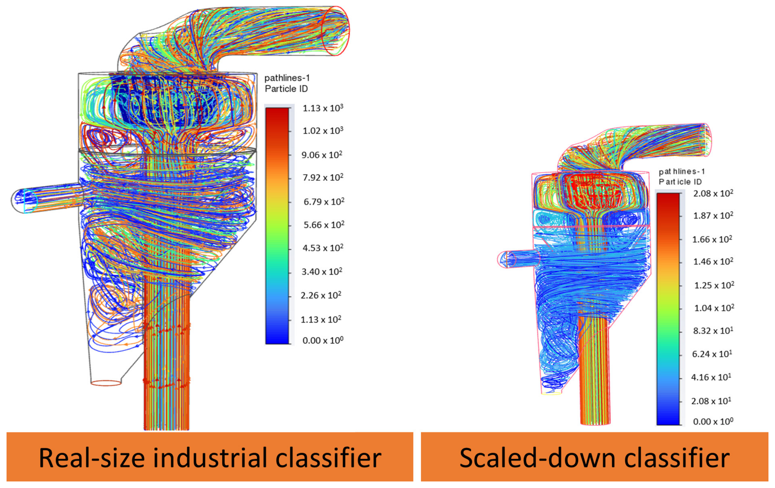
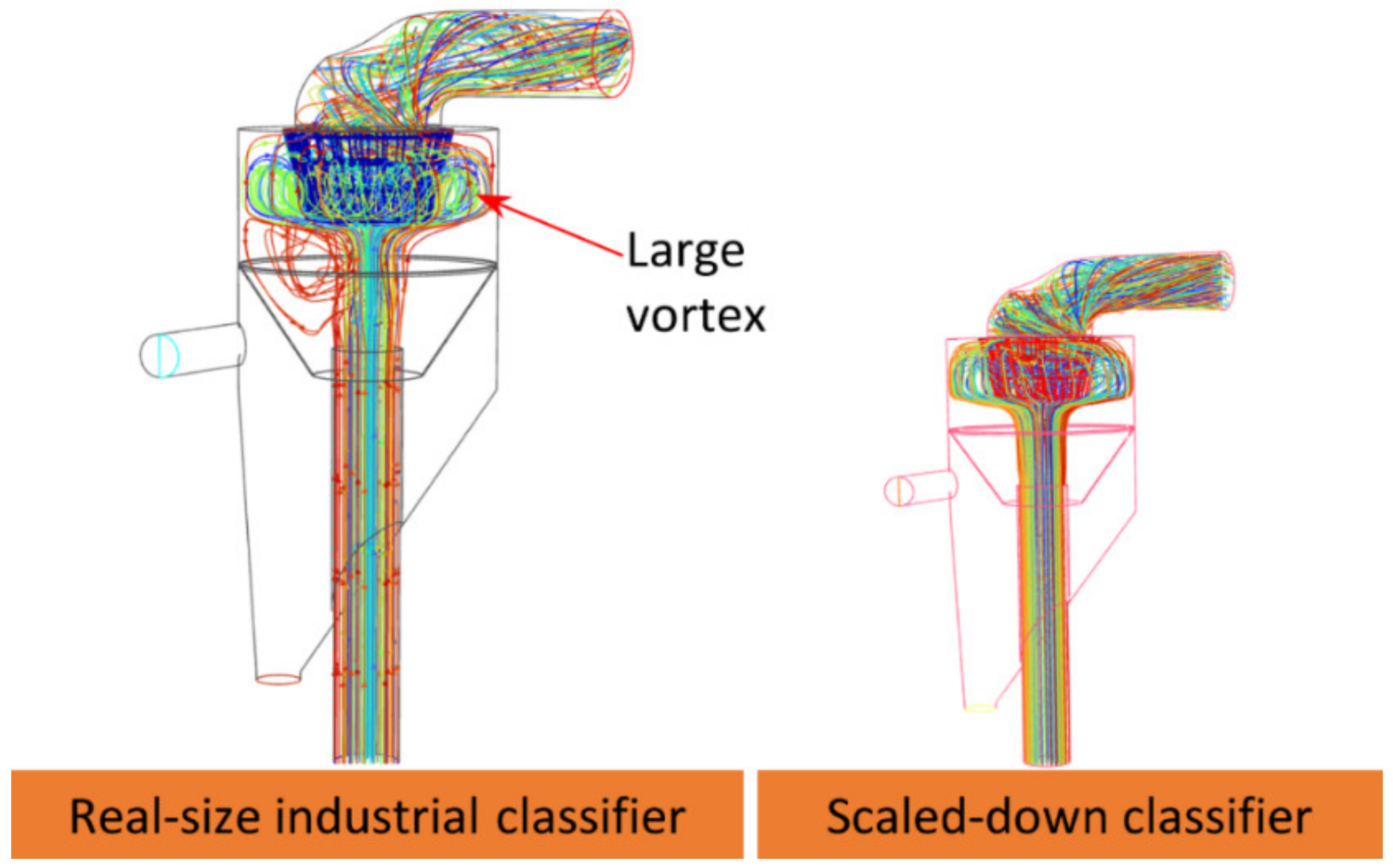
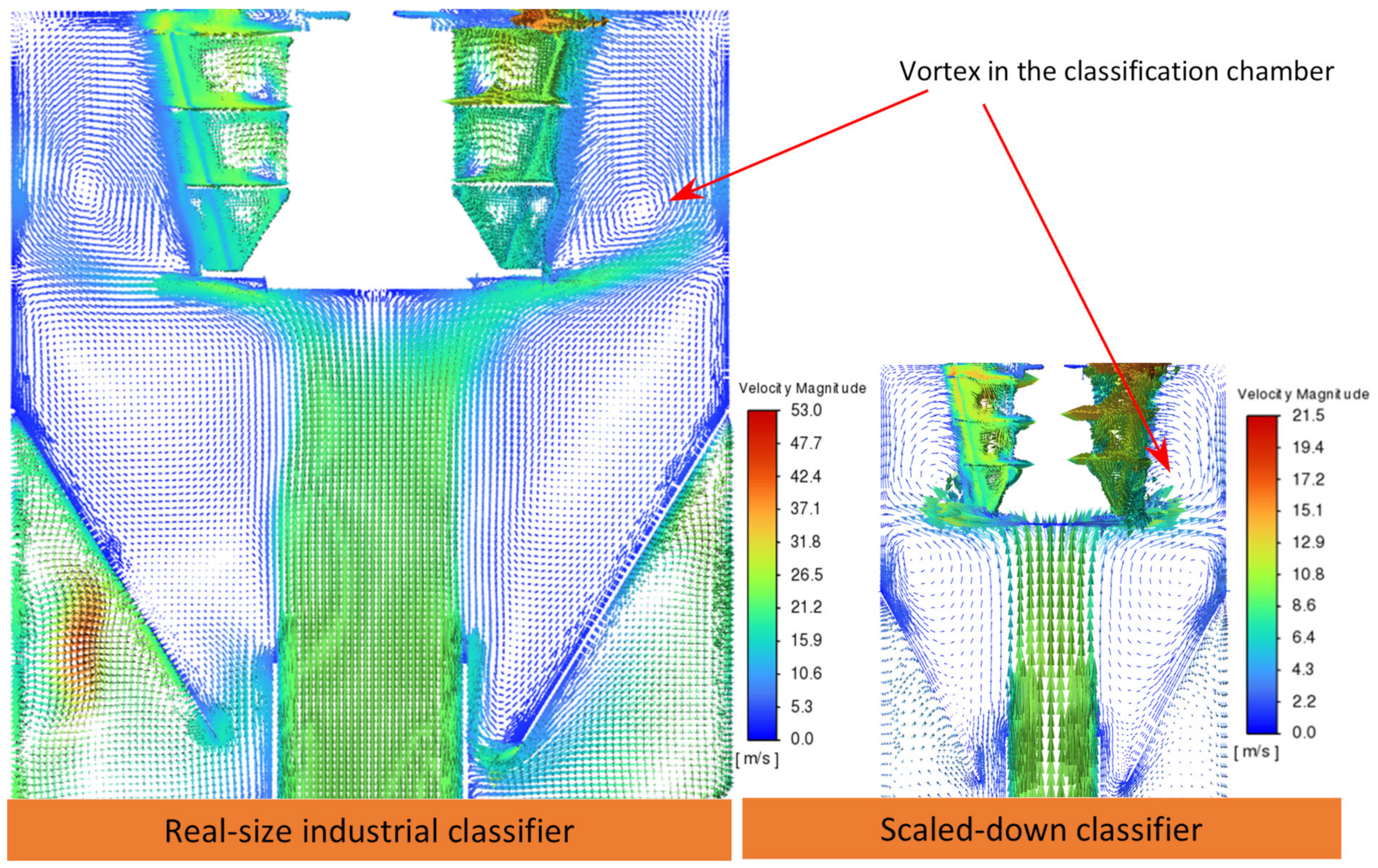
The flow field distributions within the real-sized industrial model and the prototype are illustrated in Figure 2. In both cases, after passing the impact plate, the primary airflow is divided into two parts flowing in different directions. After leaving the impact plate, the primary airflow is initially directed towards the wall and then proceeds upwards along the wall. Both the real-sized industrial model and prototype have large vortices in the guide cones. However, the locations and behaviors of the vortices forming in the classification chambers of the two models are different. These differences are more clearly presented in Figure 3 and Figure 4.
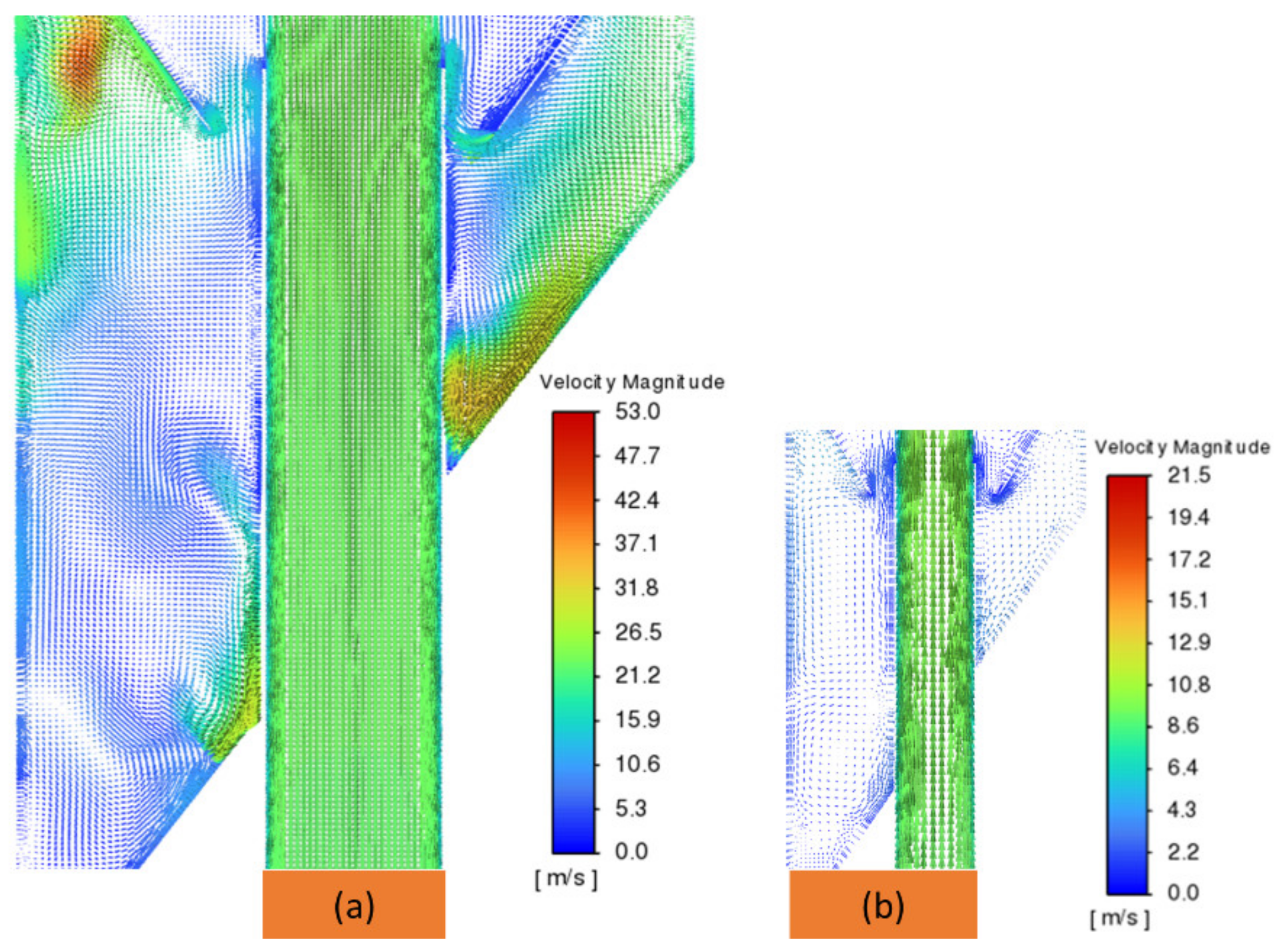
As illustrated in Figure 3 and Figure 4, the flow field inside the classification chamber of the prototype was different from the one inside the industrial model. A larger vortex was created in the classification chamber of the real-size industrial classifier. Additionally, the vortices forming in the prototype’s coarse material cone were different from those of the industrial model in terms of number, position, size, shape, and rotational direction (as shown in Figure 5).
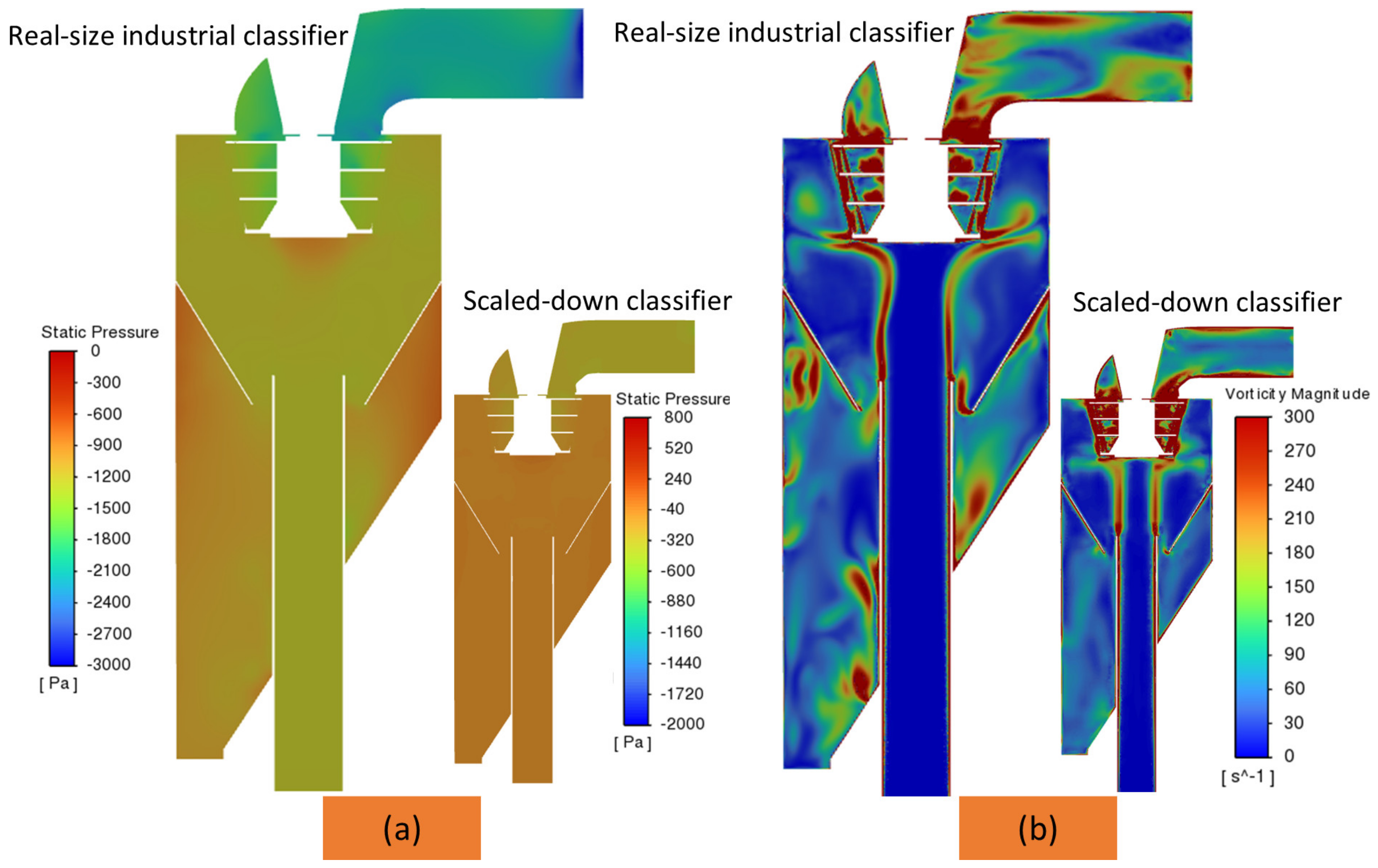
As illustrated in Figure 6a, the pressure distribution inside the prototype was different from the one inside the industrial model. The pressure inside the prototype was more uniform than that in the industrial one. The uneven pressure distribution in the coarse material cone of the industrial classifier may be the cause of the formation of many vortices of different sizes, shapes and locations in this region. This phenomenon does not appear in the prototype model. It becomes more noticeable when comparing the vorticity magnitude distribution of the industrial classifier model to the prototype (Figure 6b). It can be seen from Figure 6b that there are more and bigger vortices forming in the coarse material cone of the industrial classifier than those inside the prototype. Additionally, in comparison with the industrial one, there is stronger turbulence inside the rotor cage of the prototype because of its small size. This turbulence significantly affects the classification ability of the prototype.
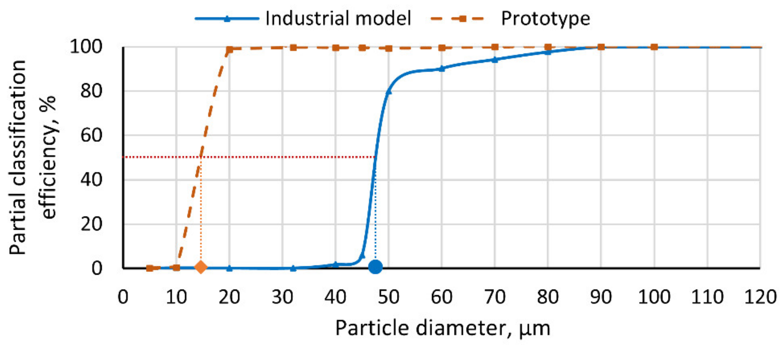
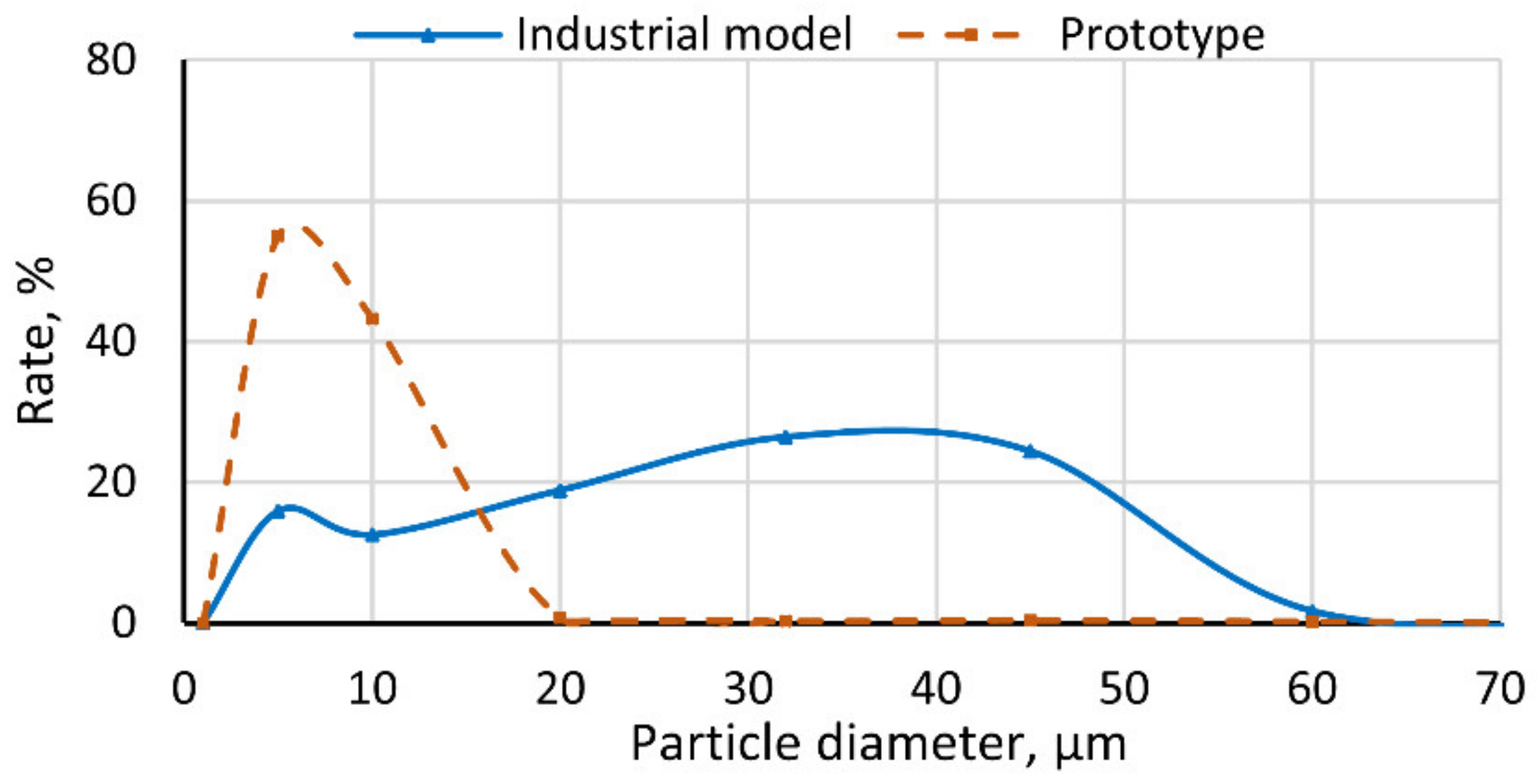
According to the results of the flow field distributions mentioned above, the flow field inside the prototype model was not as fully represented as that occurring in the real-sized industrial model. These differences are more clearly presented in the investigation of their efficiency. As depicted in Figure 7, the Tromp curves of the real-sized industrial classifier and prototype exhibited different trends. The Tromp curves for the industrial classifier and the prototype significantly decreased for particle sizes less than 45 μm and 20 μm, respectively. As a result, the prototype provided a d50 of 15 μm, whereas the industrial classifier provided a d50 of 47 μm. The industrial classifier achieved 91.79% Newton efficiency and 7059 kg/h productivity, while the prototype achieved 99.2% Newton efficiency and 680 kg/h productivity. This result shows that the size of the industrial classifier is three times bigger than the prototype, but the productivity of the industrial classifier is 10.4 times higher than that of the prototype. Additionally, these two models exhibited different article size distributions of the final products (as shown in Figure 8).
The investigation results for both the real-sized industrial model and the prototype show that the scaled-down model helps to save computational resources and time and is useful for preliminary investigations of the flow fields of air classifiers or simple models. However, it still has considerable issues in using the results of the simulation of the solid–gas two-phase flow field inside a scaled-down model to apply in real-size industrial models of classifiers. The parameters selected for models should ensure similarity not only in geometry but also in kinematics and dynamics, which is a challenging task for researchers. The above analysis indicates that despite the large computational resources and various risks involved during the calculation process, the use of an industrial air classifier model for numerical studies enables us to obtain more accurate and real flow-field characteristics. Therefore, with the aid of HPC (high-performance computing) systems, the real-sized industrial model of the classifier was chosen for continuous simulations in this study.

4.2. Influence of Outlet Mass Airflow Rate

4.2.1. Influence of Outlet Mass Airflow Rate on Flow Field Within the Classifier

Figure 9 shows the flow field, in terms of its two-dimensional velocity vectors, formed in the industrial classifier. By taking into account the influence of quartz particles on the continuous phase with two-way coupled RSM-DPM, the flow behaviors with numerous vortices in the industrial-scale real-sized classifier are thoroughly described. The classification chamber of each of the four simulation cases contains a large vortex that prevents airflow entry and reduces the rotor cage’s effective classification height. It can be seen from the figure that it has different positions under different outlet mass airflow rate conditions, denoted by M. Therefore, the rotor cage’s classification abilities under different values of M (i.e., M = M1 = 5.104 kg/s, M = M2 = 5.615 kg/s, M = M3 = 6.125 kg/s) are different. Clearly, a higher M results in a lower position of the vortex in the classification chamber when M increases in the range of 5.104–6.125 kg/s. The rotor cage’s airflow entry is facilitated by the lowest position of the vortex formed under M3, which allows more particles to enter. M3 is considered the most effective condition for the classification efficiency of the classifier.
Additionally, the guide cone and coarse material zones have a number of vortices with different rotation directions and positions, depending on the outlet mass airflow rates, thus affecting the secondary classification abilities in these zones. Unlike the remaining cases, a vortex forms just below the recirculation gap under M3, and another vortex appears just above the gap. These vortices can facilitate or hinder the recovery ability of coarse material particles and the transport of fine particles upward to the classification chamber after secondary separation. These differences in the vortices under different values of M directly influence the classification performance of the classifier. In this study, the complex multiple-phase flow field was successfully captured with the real-size industrial classifier. It is notable that it was not entirely captured in prior simulations using laboratory-scale models.
By studying the complex flow field within the real-sized industrial classifier, which features multiple vortices, one can gain a comprehensive understanding of the classification mechanism. In the subsequent sections, we will examine the impact of M on classification performance.

4.2.2. Influence of Outlet Mass Airflow Rate on Classification Efficiency

Numerical simulations give insight into the particles that escape or are trapped. To determine the degree of separation associated with varying outlet mass airflow rates, we built an efficiency curve based on the percentage of trapped particles within the total mass of the feed particles of the same size, as depicted in Figure 10.
Different trends were observed in the Tromp curves, as demonstrated in Figure 10. Particle sizes smaller than 45 µm led to a significant decrease in classification efficiency under M1 or M2. However, with the flow rate equal to M3, a significant decrease in classification efficiency occurred for particle sizes less than 80 µm. Conversely, it can be seen from Figure 10 that outlet mass airflow rates from M1 to M3 led to lower yields for coarse products due to higher airflow rates, while the opposite was true for fine products. The reason for these behaviors is the differing particle terminal velocities; more large particles were present in the fine product when the airflow rates were higher, as their terminal velocity was exceeded. However, increasing the outlet mass airflow rate resulted in an increase in d50 from 44 µm to 64 µm. We also found a similar trend in the literature, e.g., in refs. [3,23,24]. Specifically, at M1, M2, and M3, the micron air classifier achieved Newton efficiencies of 76.15%, 91.79%, and 94.8%, respectively. In addition, the flow rate equal to M1, M2, and M3 yielded K values equal to 1.41, 1.09, and 1.14, respectively. These K values are excellent [6]. The values of these indices demonstrate that the flow rate set at M3 provides the highest classification efficiency.

4.2.3. Influence of Outlet Mass Airflow Rate on Particle Size Distribution

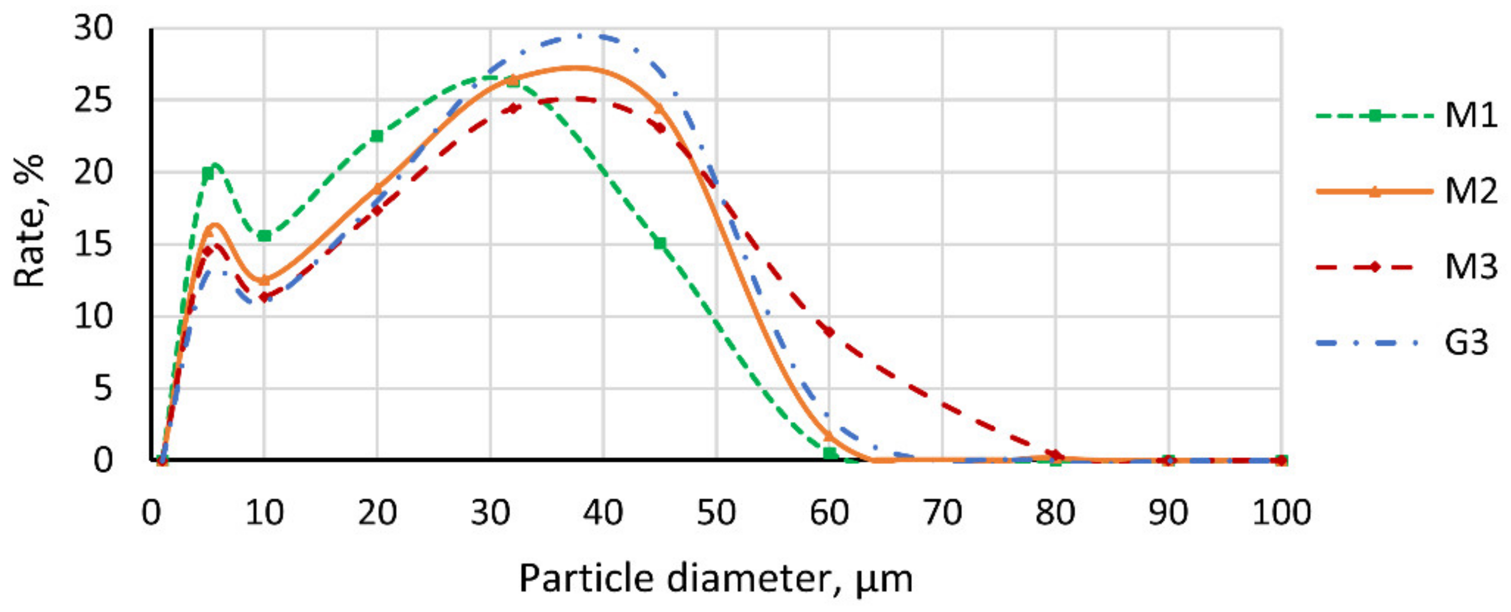
Figure 11 illustrates that the final products’ particle size distributions differed considerably. A comparison between the cases shows that both M1 and M2 provided distribution curves that satisfy KHC (G3), while M3 did not. However, the classification efficiency of the classifier at M2 was higher than that at M1 (as mentioned in Section 4.2.2). A higher outlet mass airflow rate leads to a wider particle size range in the classification product. In addition, the present simulation results suggest that we can achieve higher productivity by increasing the mass rate of airflow at the outlet. For instance, the productivity increased from 5637 kg/h to 7652 kg/h by increasing this mass airflow rate from M1 to M3.
Our aforementioned analysis reveals that the classification performance (evaluated by key performance indicators: d50, K, η) and the flow behaviors are strongly influenced by the outlet mass flow rate. In particular, we observed higher yields of fine products and lower yields of coarse products with higher airflow rate values. The flow rate of 5.104 kg/s yielded a classification sharpness index of 1.09, while the flow rate of 6.125 kg/s resulted in K = 1.41. This confirms the good accuracy of the classification. In addition, increasing this flow rate also led to an increase in the cut size. The evaluation of the classification performance based on these indices shows that M3 provides the highest classification efficiency, but the highest cut size. The size distribution of the final product particles under M3 did not satisfy KHC. Conversely, both M1 and M2 provided distribution curves satisfying KHC (G3), but the classification efficiency of the classifier at M2 was higher than that at M1. Moreover, M2 provided the highest classification accuracy at K = 1.09. Therefore, M2 was the best outlet mass airflow rate for the classifier to achieve the highest classification efficiency possible under the constrained condition of KHC in producing fine powder (0–45 μm). M2 (5.615 kg/s) was also chosen as the input data for the next simulation.

4.3. Influence of Rotor Speed

4.3.1. Influence of Rotor Speed on the Flow Field Within the Classifier

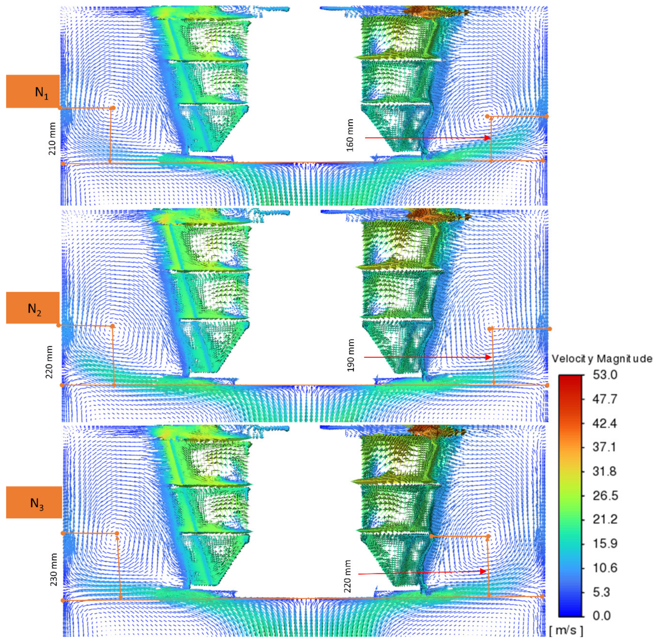
Figure 12 presents 2D vector graphs of the airflow velocity field at different rotor speeds, denoted as N. The rotor speed is set at different values: N = N1 = 290 rpm, N = N2 = 310 rpm, N = N3 = 330 rpm. A large vortex forms near the lower part of the rotor cage in the classification chamber. The airflow is prevented from entering the rotor cage by this vortex, which reduces the effective classification height of the rotor cage. Figure 12 that the vortex on the right side and that on the left side is asymmetrical in all cases of different speeds of rotor. Using N1 as an example, the vortex’s position on the right side is lower than on the left side of the classification chamber. However, the positions of the vortices in the classification chamber are different under different rotor speeds. N1 provides the vortex with the lowest position in the classification chamber. As mentioned above, as this vortex is located at a lower position, the material particle separation process is more favorable, resulting in a smoother entry of the particles to the rotor cage. Therefore, it is predicted that the classifier achieves the highest classification efficiency under N1 in comparison to the remaining cases. The effects of rotor speeds on the classification performance of the classifier are further analyzed in subsequent sections.

4.3.2. Influence of Rotor Speed on Classification Efficiency

It can be seen from Figure 13 that there is no fish-hook effect. The rotor speed of 290 rpm (N1) yields a Tromp curve with a gradual decrease and then a sharp decrease as the particle size decreases below 50 µm (the triangle/solid line in Figure 13). Similar behaviors but with particle sizes below 45 µm and 40 µm are observed, respectively, for the rotor speed equal to 310 rpm (N2) and 330 rpm (N3) (see the dashed line for N2 and the dotted line for N3 in Figure 13). The Tromp curve moves to the left as N increases from 290 to 330 rpm. It can be seen that the degree of separation is determined by varying rotor speeds. Therefore, according to the Tromp curves, we can roughly estimate the classification sharpness index as well as the cut size when varying the rotor speed. When the rotor speed increases from 290 rpm to 330 rpm, Newton’s efficiency gradually decreases from 91.79% to 81.11%, and d50 decreases by 29.8%. It is clear that the higher the rotor speed, the lower the d50. The rotor speed of 290 rpm provides the smallest K, while the 310 rpm rotor speed provides the highest. Analyzing the results yielded by different rotor speeds shows that the N1 with the rotor speed of 290 rpm gives the highest classification efficiency (91.79%) and achieves the best classification accuracy with K = 1.087. This demonstrates that rotor speeds have significant effects on the classification efficiency of the classifier.

4.3.3. Influence of Rotor Speed on Particle Size Distribution

Figure 14 confirms that there is clearly a difference in the particle size distributions of the final products under the three different rotor speeds. Each rotor speed provides different particle size distributions. In the technology of producing quartz-based engineering stone, each product pattern has its own formula that needs a specific quartz powder particle size distribution curve. The abovementioned results indicate that the control of the rotor speed can be a good solution to achieve the desired separation quality with different types of products. In terms of the objective of this study, only a rotor speed of 290 rpm (N1) can provide the distribution curves that satisfy the KHC (G3). Additionally, N1 provides the highest classification efficiency and the highest classification accuracy with K = 1.09. Therefore, N1 (290 rpm) is the best rotor speed for the classifier to achieve the highest classification efficiency under the constrained condition of the KHC in the production of fine powder (0–45 μm). The rotor speed of 290 rpm was chosen as the input data for the next simulation.

4.4. Influence of Secondary Inlet’s Airflow Velocity

Considering the partial optimization for the outlet mass airflow rate and rotor speed and the actual working condition limits, five secondary inlet airflow velocities (denoted as V) were set: V1 = 14 m/s; V2 = 22 m/s; V3 = 29 m/s; V4 = 36 m/s; and V5, where the secondary inlet valve was open to allow fresh air in.

4.4.1. Influence of Secondary Inlet’s Airflow Velocity on the Flow Field Within the Classifier

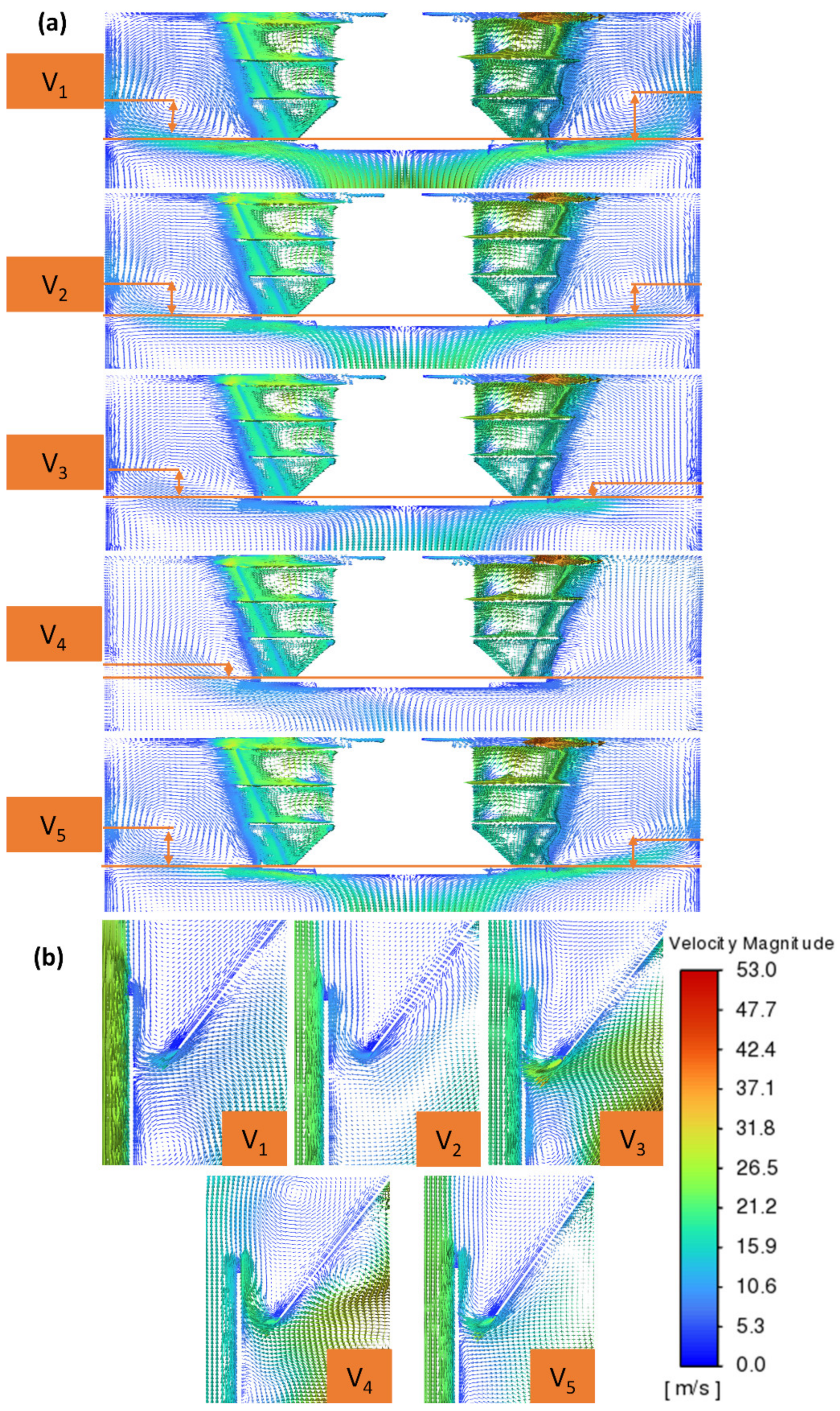
Figure 15 shows that the secondary inlet’s airflow velocity significantly affected the complex flow field within the industrial classifier. When V increased from 14 m/s to 36 m/s, the vortex with its shape, size, and position behaved very differently in the classification chamber. This vortex under V4 also differed from those under V1, V2, V3, and V5. It can be seen from Figure 15a that the higher the secondary inlet airflow velocity, the lower the position of the vortex and the closer the rotor cage surface, which is more favorable for the material particle separation process, as the gas–particle flow enters the rotor cage more smoothly. The vortex that formed under V4 was at the lowest position and very close to the bottom outer surface of the rotor cage. Therefore, the airflow directly entered the rotor cage without being directed toward the wall. It can be inferred that the classification process may become more efficient when V increases.
The abovementioned analysis shows that the auxiliary air source performs two functions: (1) balancing the pressure between the secondary zones, and (2) providing additional classification in the coarse particle cone. Figure 15b shows that the secondary inlet airflow velocity also has a strong influence on the flow field in the secondary classification zones (the coarse particle cone zone and the guide cone zone). In particular, the vortices forming just below or above the recirculation gap under different secondary inlet airflow velocities are entirely different, resulting in different secondary abilities in these secondary classification regions. These effects of the secondary inlet airflow velocity have not been reported in past studies using one-way coupling steady simulation for lab-scale models of classifiers. Additionally, the effects of secondary inlet airflow velocity are more clearly illustrated when observing the airflow path line shown in Figure 16, Figure 17 and Figure 18.
The flow field distribution within the industrial air classifier is depicted in Figure 16. The airflow movement route is created by the combination of primary and secondary air. The primary air stream comes from the bottom of the primary air inlet. It continues moving upward to the classification chamber after passing the impact plate. The horizontal cross of the classification abruptly increases, leading to a decrease in the primary airflow velocity. After passing the impact plate, the primary airflow is divided into two parts in two different directions. After first leaving the impact plate and then being directed towards the wall, the main part of the primary airflow rises upwards along the wall. This flow turns to enter the rotor after hitting the classification chamber’s upper surface. Most of the airflow moves into the rotor in the diagonal direction, deflects into the rotating rotor cage, and flows out through the fine product outlet. For the remaining primary airflow, after leaving the impact plate, it flows downward, thereby driving the coarse particles to enter the coarse material cone. It can be seen that the primary airflow and the secondary airflow inside the industrial classifier are controlled independently. The primary airflow mainly occupies the main regions (as shown in Figure 17), while the secondary airflow mainly occupies the secondary classification regions (as shown in Figure 18). The secondary airflow arrives from the secondary air inlet, which can re-clean the material particles in these secondary classification regions. However, variations in the secondary inlet airflow velocity significantly affect the flow field in both the main and secondary classification zones. It can be seen that the flow field, characterized by turbulence with multiple vortices, is different under different secondary inlet airflow velocities. To prevent mutual interference between the primary and secondary airflows, it is necessary to control the primary airflow volume and secondary airflow velocity separately. The respective flow field within the industrial micron air classifier could be realized in this way. The effects of secondary inlet airflow velocity on the classification performance will be more thoroughly analyzed in the next section.

4.4.2. Influence of Secondary Inlet’s Airflow Velocity on Classification Efficiency

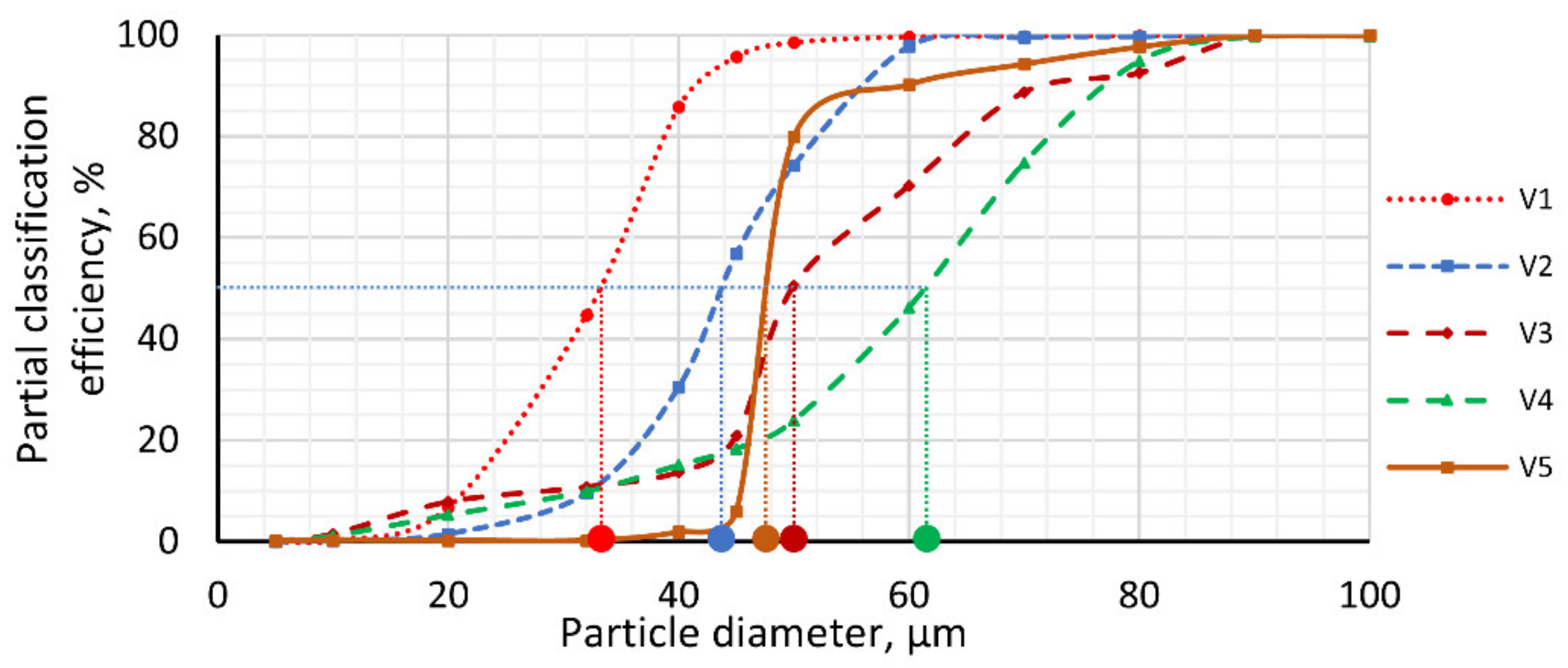
As shown in Figure 19, the Tromp curves differ under different secondary inlet air velocities. The classification efficiency experiences a sharp decrease for particle sizes below 45 µm under V1, below 50 µm under V5, below 60 µm under V2, and below 80 µm under V3 or V4. Notably, there is no fish-hook effect in any of the five simulation cases. However, it can be seen from Figure 19 that the Tromp curve under V5 has the steepest slope. Therefore, the classifier achieves the highest classification efficiency under V5. However, when V increases, η increases from 76.04% to 91.79%, and K decreases from 1.42 to 1.09. The values of d50 corresponding to V1, V2, V3, V4, and V5 are 33, 43.5, 50, 64.3, and 47 μm, respectively. This analysis demonstrates the best classification performance corresponding to the secondary inlet air velocity of V5.

4.4.3. Influence of Secondary Inlet’s Airflow Velocity on Particle Size Distribution

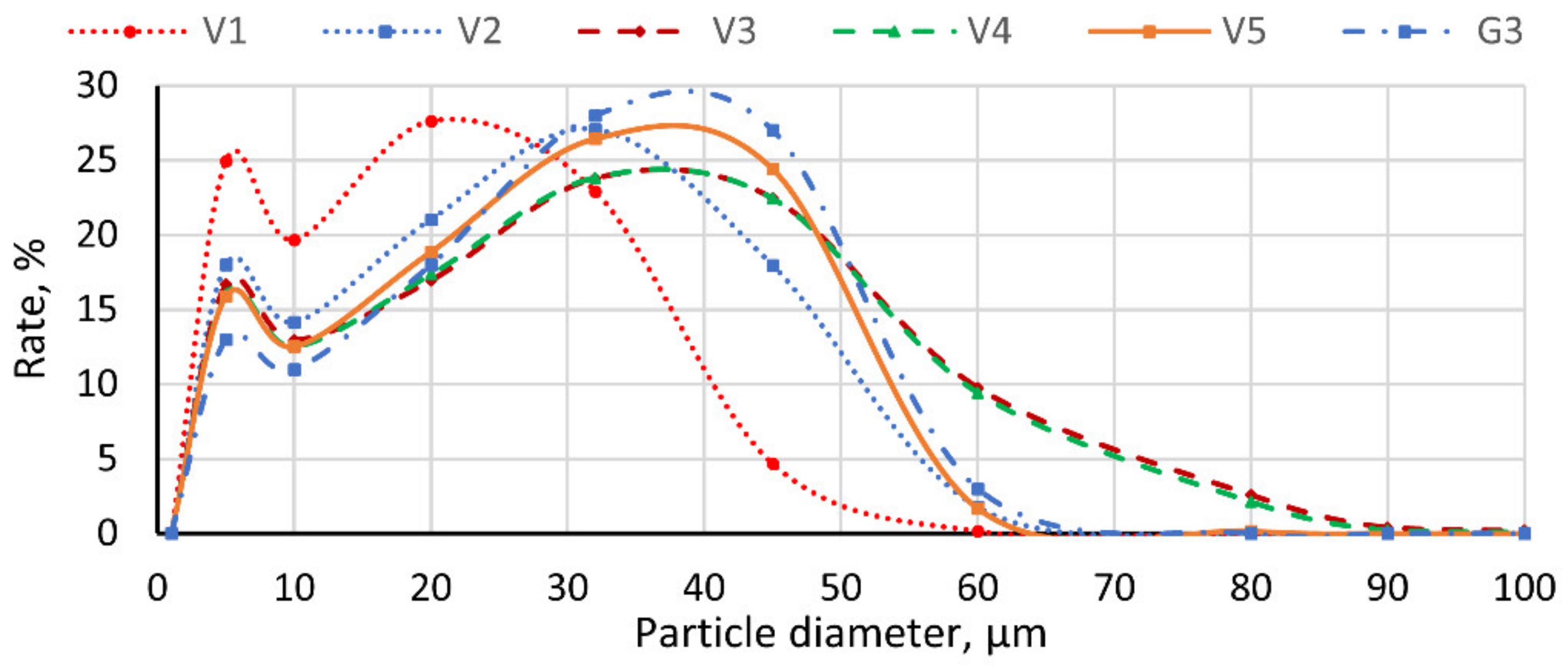
Figure 20 shows that the particle size distributions of the final products depend on the secondary inlet air velocities. In particular, when V is 14 m/s, the product particle size distribution is in a narrower size range (0–50 μm) and differs from the remaining cases. Therefore, if a fine powder size of less than 50 μm is the production goal, the separation mode with a secondary air velocity of 14 m/s should be prioritized. However, this gives low classification efficiency (76.05%). Our goal is to determine the classifier’s optimal process parameters to achieve the highest possible efficiency for classifying particle products applied for quartz-based engineering stones. Simultaneously, the approach must satisfy constrained conditions such as the KHC for the fine powder (0–45 μm) used in quartz-based engineering stone. Figure 20 illustrates that the particle size distribution curve under V5 is closest to G3. Moreover, the highest classification efficiency (η) is achieved under V5. Therefore, the classifier may achieve the best classification performance with V5.

4.5. Relationships Between Operating Parameters, Classification Performance, and Optimal Parameters

It can be seen from Section 4.4 that the classifier achieves the highest classification efficiency (η) under V5. When V increases, η increases from 76.04% to 91.79% and K decreases from 1.42 to 1.09. The values of d50 corresponding to V1, V2, V3, V4, and V5 are 33, 43.5, 50, 64.3, and 47 μm, respectively. Therefore, the most suitable secondary inlet airflow velocity (V5) was chosen for analyzing the relationships between the operating parameters and classification performance.
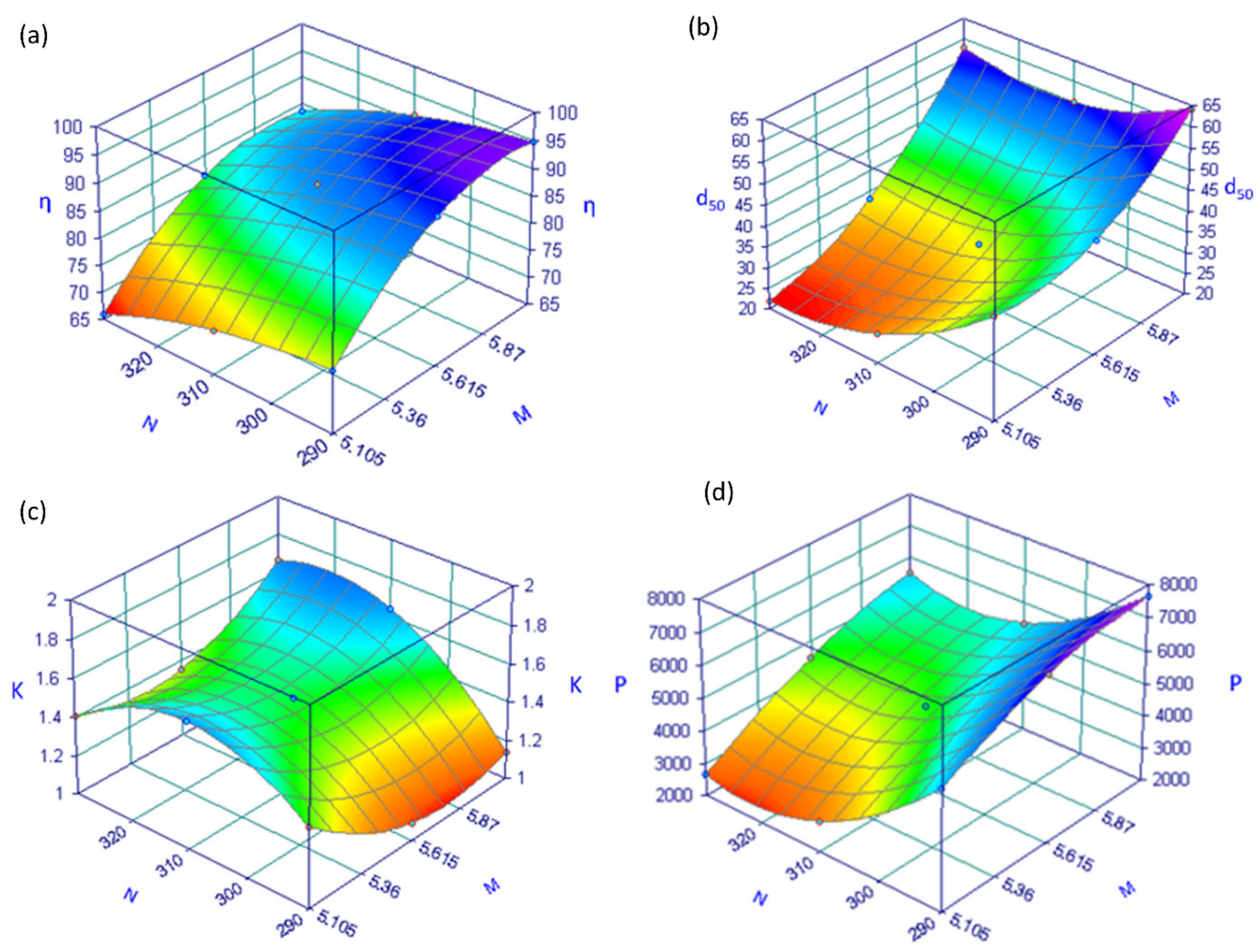
Figure 21 shows 3D surface plots of Newton’s classification efficiency (η), cut size (d50), classification sharpness index (K), and fine powder productivity (P), illustrating the effects of two varying operational parameters (N, M) on η when the other operating conditions (Qp-feed rate and V-secondary inlet airflow velocity) remained constant. It can be seen from Figure 21 that a higher airflow rate results in higher yields for fine products and Newton classification efficiency, and vice versa for rotor speed: when N increases, both η and P decrease. Similarly, when the outlet mass airflow rate increases, d50 also increases. However, d50 decreases when N increases. Additionally, when the classification accuracy increases, K decreases correspondingly, and then decreases when M increases. Analyzing the classification performance based on these indices shows that M3 provides the highest cut size with the highest classification efficiency. Moreover, the particle size distribution of the final product under M3 does not satisfy the KHC. Conversely, both M1 and M2 provide distribution curves that satisfy the KHC, but the classification efficiency of the classifier at M2 is higher than that at M1. Moreover, M2 provides the highest classification accuracy. However, the particle size distributions of the final product are different at different rotor speeds, indicating that controlling the rotor speed can be a good solution to achieve the desired separation quality with different types of products. Only a rotor speed of 290 rpm provides distribution curves that satisfy the KHC.
Our goal was to find out the classifier’s optimal process parameters to obtain the best classification performance, as evaluated via classification indices such as cut size (d50), classification sharpness index (K), and the Newton classification efficiency (η) under the constrained conditions of the KHC (G3) of quartz fine powder (0–45 μm). Based on these indices, the classifier achieves the highest classification efficiency (91.79%) under the KHC (G3) constrained condition for quartz fine powder (0–45 μm) at the optimal set of operating parameters as the following: the rotor speed of 290 rpm, the outlet mass airflow rate of 5.615 kg/s, the feed rate of 2.44 kg/s, and the setting condition of fresh air at the secondary inlet.

5. Experiment

5.1. Experimental Setup

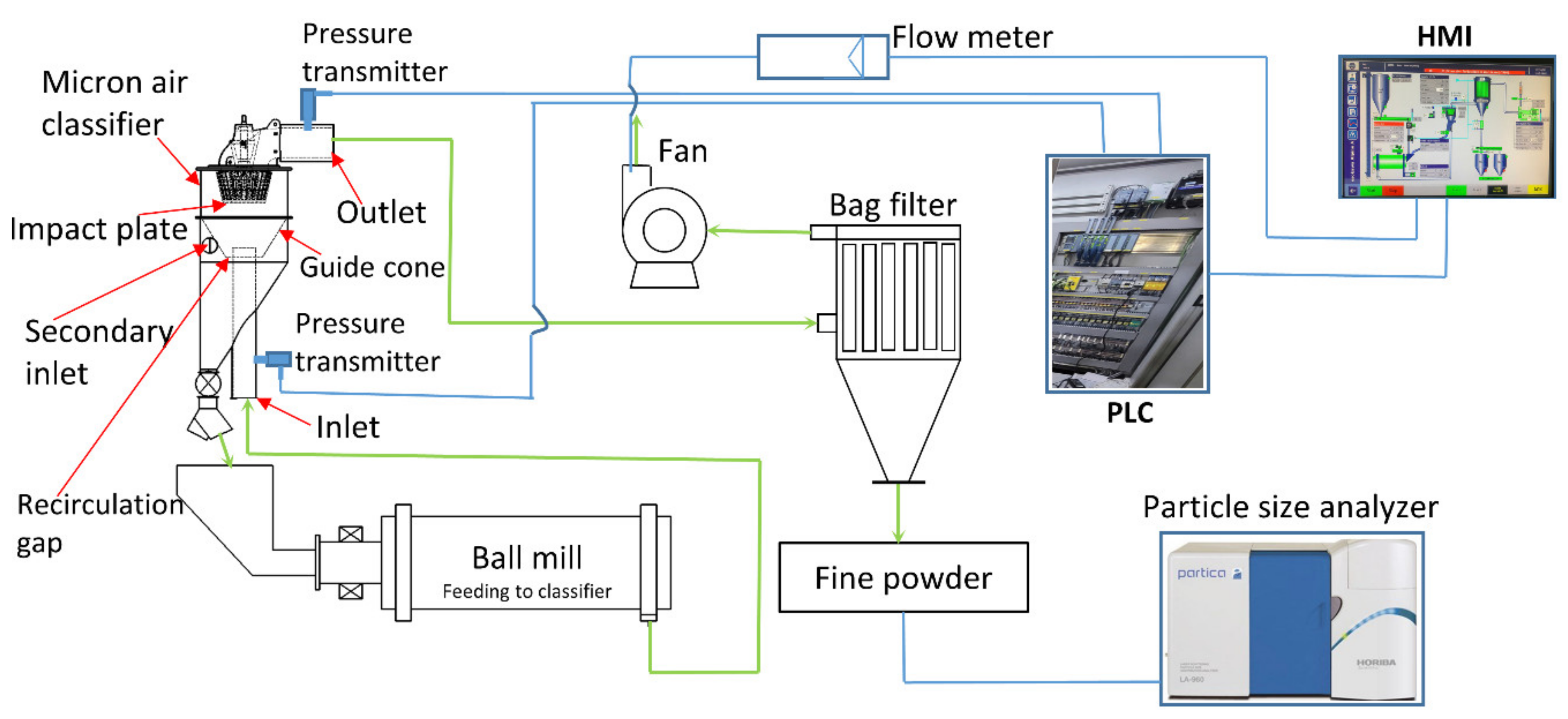
The simulation results (particle size distribution, pressure drop, classification productivity) were compared with the corresponding experimental data. The experiment was conducted at the Vicostone Plant. All measurements were done using sensors and equipment certified by CE (Conformité Européenne). The scheme of the experimental setup is shown in Figure 22 with the industrial classification and measuring systems shown in Figure 23. Firstly, the particle size distribution curves were compared to the KHC (as shown in Figure 11, Figure 14 and Figure 20). The KHC was achieved based on the production process carried out for a few decades at the Vicostone Plant of the Phenikaa Group
To ensure the reliability of the simulation results, the predicted particle size distribution curves were verified using the experiment curves obtained under the same operating conditions with the optimal operating parameters (i.e., a rotor speed of 290 rpm (N1), a feed rate of 2.44 kg/s, an outlet mass airflow rate of 5.615 kg/s (M2), and setting condition of fresh air at the secondary inlet) and particle sizes ranging from 0 to 600 μm. The particle size of the quartz powder was measured using an Alpine Air Jet sieve (e200 LS (Hosokawa, Augsburg, Germany)) and a particle size analyzer LA-960 (HORIBA, Kyoto, Japan). The drop in pressure, defined as the change in the average static pressure from the inlet to the outlet, was also used to confirm the accuracy of the computational calculations. These pressures were measured using pressure transmitters (STS ATM 1000634 (STS Sensor Technik Sirnach AG, Sirnach, Switzerland)). In addition, a flow meter (FC 01-Flow vision GmbH Im Erlet 6 90518 Altdorf, Germany), and a human–machine interface (HMI) screen (Etop 515 (Exor)) were used in this study.

5.2. Experiment Results and Analysis

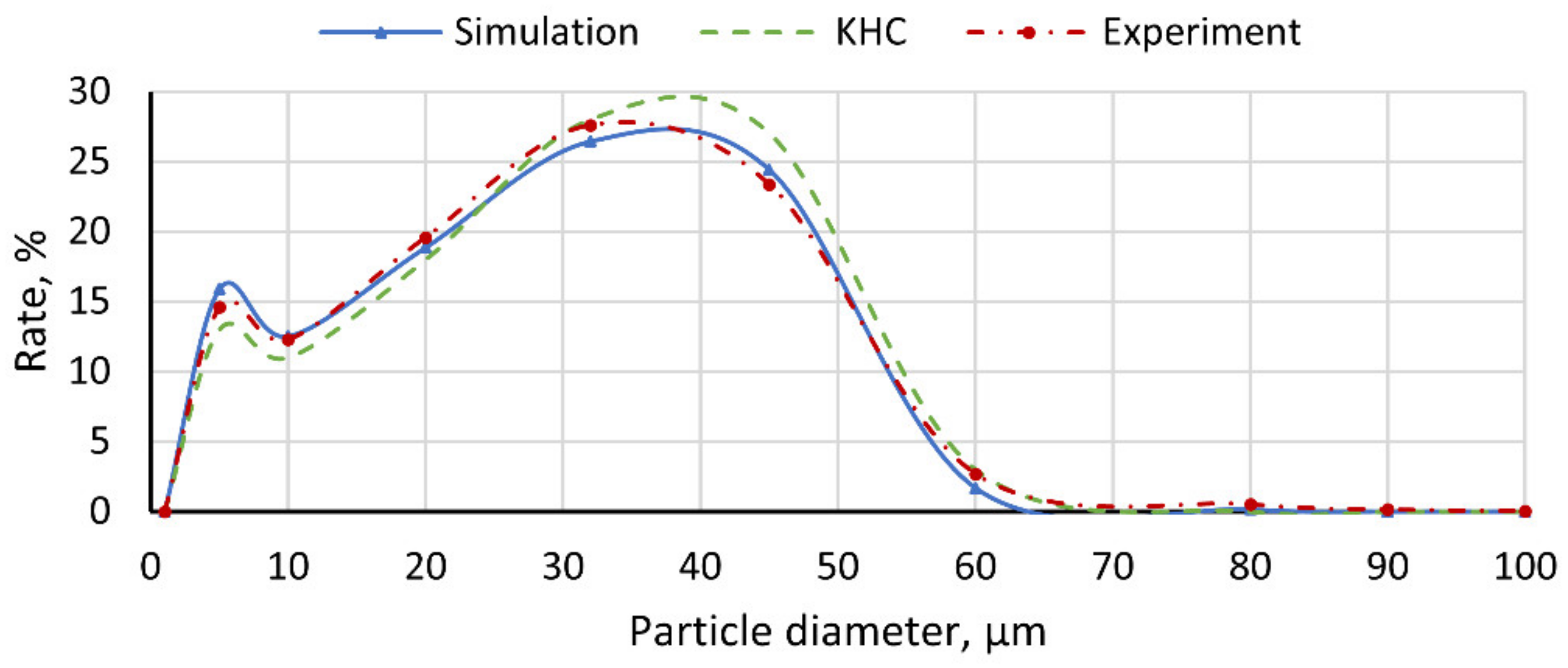
The comparison between the particle size distribution curve of the current simulation and the experimental results from the Vicostone Plant (as shown in Figure 24) illustrates that the predicted particle size distribution curve according to the simulation is close to that obtained from the experiment and satisfies the KHC for quartz fine powder (0–45 μm). This fine powder is currently being used to manufacture quartz-based engineering stone at the Vicostone Plant of the Phenikaa Group.
The data in Table 5 show slight differences (8.2% for productivity and 8.5% for pressure drop) between the experiment conducted at the Vicostone Plant and the simulation. This confirms the good agreement between the experiment and the simulation, supporting the accuracy of our calculations.

6. Conclusions

We have presented the three-dimensional simulation results for both a prototype model and its real-sized industrial-scale classifier. All calculations were done using TWC-RSM-DPM implemented in the commercial software named ANSYS Fluent (version 2022 R2) running on the HPC system at Phenikaa University. By such a calculation method in the present study, we considered the two-way interactions between the gas phase and particles. These results help to develop an understanding of the main factors that impact on the flow field and the classification mechanism of an actual-sized industrial classifier. The accuracy of the simulation was confirmed by comparing the experimental data with the corresponding simulation results. The following conclusions were obtained:
  • The structure of the multiphase flow field within the industrial-scale micron gas classifier under different operating parameters was successfully identified and thoroughly analyzed. The results showed that the structure of the flow field, in terms of turbulence and the behaviors of the vortices, directly influences the classifier’s classification performance. There were significant differences in the flow field between the real-sized industrial-scale classifier and the prototype, highlighting the necessity of simulation studies on a real-size industrial-scale model for optimization purposes (as outlined in Section 4.1).
  • The relationship between operating parameters and classification performance was addressed through partial optimization, and then the optimal set of operating parameters was examined and selected (as described in Section 4.5). The analysis showed that (i) an increase in the airflow rate results in higher yields for fine products; (ii) the higher the rotor speed, the higher the classification accuracy, but the lower the yields for fine products; and (iii) the higher the secondary inlet airflow velocity, the higher the Newton efficiency.
  • Each operating parameter set had its own size distribution curve of particles. Each production process (of quartz-based engineering stone) may require a specific size distribution of particles, and thus one can choose a particular set to achieve the best corresponding classification performance.
  • The experimental results, as measured using equipment and sensors certified by CE, showed good agreement with the simulated result, indicating the reliability of our computations.

Author Contributions

Formal analysis, N.X.H. and H.T.D.; investigation, N.X.H. and H.T.D.; methodology, N.X.H. and H.T.D.; supervision, N.X.H. and N.T.D.; validation, H.T.D.; visualization, N.T.D.; writing—original draft, N.X.H. and H.T.D.; writing—review and editing, N.X.H. and H.T.D. All authors have read and agreed to the published version of the manuscript.

Funding

This research received no external funding.

Data Availability Statement

The data that support the findings of this study are available within the article.

Acknowledgments

The authors are grateful to Phenikaa University, the Vicostone Plant, the Phenikaa Group, and the Advanced Technology Joint Stock Company for supporting this work. The calculations in this work were performed using HPC systems at Phenikaa University.

Conflicts of Interest

The authors declare that this research was conducted in the absence of any commercial or financial relationships that could be construed as potential conflicts of interest.

Abbreviations

The following abbreviations and mathematical symbols are used in this manuscript:
CFDComputational Fluid Dynamics
CHLGuide Cone
DPMDiscrete-Phase Model
HPCHigh-Performance Computing
KHCKnow-How Curve
KPIsKey Performance Indicators
PSDCParticle Size Distribution Curve
QUICKQuadratic Upwind Interpolation of Convective Kinematics
RSMReynolds Stress Model
SIMPLECSemi-Implicit Method for Pressure-Linked Equations Consistent
TWCTwo-Way Coupling
d50Cut Size
gGravitational Acceleration
KClassification Sharpness Index
mpParticle Mass
pPressure
tTime
uAverage Fluid Velocity
u′Fluctuating Fluid Velocity
upParticle Velocity
τrRelaxation time
εVolume Fraction Locally Occupied by Fluid
ηNewton Classification Efficiency
ρFluid Density
ρπParticle Density

References

  1. Lagad, N.R.; Jadhav, S.M. Investigation into Effect of Rotor RPM on Degree of Separation in Air Classifier. Int. J. Sci. Res. (IJSR) 2015, 6, 539–544. [Google Scholar]
  2. Johansson, R. Air Classification of Fine Aggregates; Doktorsavhandlingar vid Chalmers Tekniska Högskola; Chalmers Univ. of Technology: Göteborg, Sweden, 2014; ISBN 978-91-7597-136-0. [Google Scholar]
  3. Ho, N.X.; Dinh, H.T.; Dau, N.T.; Nguyen, B.H. A Numerical Study on the Flow Field and Classification Performance of an Industrial-Scale Micron Air Classifier under Various Outlet Mass Airflow Rates. Processes 2024, 12, 2035. [Google Scholar] [CrossRef]
  4. Johansen, S.T.; Anderson, N.M.; De Silva, S.R. A two-phase model for particle local equilibrium applied to air classification of powders. Powder Technol. 1990, 63, 121–132. [Google Scholar] [CrossRef]
  5. Yang, Q.L.; Liu, J.X.; Zhou, Y.B. Flow Field Characteristic Analyses of a Turbo Air Classifier’s Rotor Cage and Its Structurally Improved Counterpart. AMR 2008, 58, 59–67. [Google Scholar] [CrossRef]
  6. Zeng, Y.; Zhang, S.; Zhou, Y.; Li, M. Numerical Simulation of a Flow Field in a Turbo Air Classifier and Optimization of the Process Parameters. Processes 2020, 8, 237. [Google Scholar] [CrossRef]
  7. Guo, L.; Liu, J.; Liu, S.; Wang, J. Velocity Measurements and Flow Field Characteristic Analyses in a Turbo Air Classifier. Powder Technol. 2007, 178, 10–16. [Google Scholar] [CrossRef]
  8. Yu, Y.; Ren, W.; Liu, J. A New Volute Design Method for the Turbo Air Classifier. Powder Technol. 2019, 348, 65–69. [Google Scholar] [CrossRef]
  9. Sun, Z.; Sun, G.; Liu, J.; Yang, X. CFD Simulation and Optimization of the Flow Field in Horizontal Turbo Air Classifiers. Adv. Powder Technol. 2017, 28, 1474–1485. [Google Scholar] [CrossRef]
  10. Xia, B.; Chen, Y.; Chen, B. Numerical Simulation Analysis of Ultrafine Powder Centrifugal Classifier. In Proceedings of the 5th International Conference on Information Engineering for Mechanics and Materials, Hohhot, China, 25–26 July 2015; Atlantis Press: Paris, France, 2015; pp. 216–221. [Google Scholar]
  11. Denmud, N.; Baite, K.; Plookphol, T.; Janudom, S. Effects of Operating Parameters on the Cut Size of Turbo Air Classifier for Particle Size Classification of SAC305 Lead-Free Solder Powder. Processes 2019, 7, 427. [Google Scholar] [CrossRef]
  12. Peng, J.; Hui, C.; Zhao, Z.; Fang, Y. Research and Optimization of Operating Parameters of a Rotor Classifier for Calcined Petroleum Coke. Processes 2024, 12, 603. [Google Scholar] [CrossRef]
  13. Sun, Z.; Sun, G.; Yang, X.; Yuan, Y.; Wang, Q.; Liu, J. Effects of Fine Particle Outlet on Performance and Flow Field of a Centrifugal Air Classifier. Chem. Eng. Res. Des. 2017, 117, 139–148. [Google Scholar] [CrossRef]
  14. Braun, R.M.; Kolacz, J.; Hoyer, D.I. Fine Dry Comminution of Calcium Carbonate in a Hicom Mill with an Inprosys Air Classifier. Miner. Eng. 2002, 15, 123–129. [Google Scholar] [CrossRef]
  15. Zeng, C.; Liu, C.H.; Chen, H.Y.; Zhang, M.; Fu, Y.; Wang, X. Effects of secondary air on the classification performances of LNJ-36A air classifier. Chem. Ind. Eng. Prog. 2015, 11, 3859–3863. [Google Scholar] [CrossRef]
  16. Zhao, Z.; Hui, C.; Peng, J.; Fang, Y. Influence of Secondary Air on the Flow Field of NGZF Classifier. Therm. Sci. 2024, 28, 4637–4653. [Google Scholar] [CrossRef]
  17. Jia, F.; Mou, X.; Fang, Y.; Chen, C. A new rotor-type dynamic classifier: Structural optimization and industrial applications. Processes 2021, 9, 1033. [Google Scholar] [CrossRef]
  18. Li, Q.; Mou, X.; Fang, Y. Effects of a Guide Cone on the Flow Field and Performance of a New Dynamic Air Classifier. Processes 2022, 10, 874. [Google Scholar] [CrossRef]
  19. Kesseler, M.; Heller, V.; Turnbull, B. A Laboratory-Numerical Approach for Modelling Scale Effects in Dry Granular Slides. Landslides 2018, 15, 2145–2159. [Google Scholar] [CrossRef]
  20. Ahmad, T.; Plee, S.L.; Myers, J.P. Fluent Theory Guide; ANSYS: Canonsburg, PA, USA, 2021. [Google Scholar]
  21. Büttner, H. Dimensionless Representation of Particle Separation Characteristic of Cyclones. J. Aerosol Sci. 1999, 30, 1291–1302. [Google Scholar] [CrossRef]
  22. Frank, M.W. Fluid Mechanics, 7th ed.; McGraw-Hill: New York, NY, USA, 2011. [Google Scholar]
  23. Pant, K.; Crowe, C.T.; Irving, P. On the Design of Miniature Cyclones for the Collection of Bioaerosols. Powder Technol. 2002, 125, 260–265. [Google Scholar] [CrossRef]
  24. Galletti, C.; Rum, A.; Turchi, V.; Nicolella, C. Numerical Analysis of Flow Field and Particle Motion in a Dynamic Cyclonic Selector. Adv. Powder Technol. 2020, 31, 1264–1273. [Google Scholar] [CrossRef]
Figure 1. The air classifier with (a) some main components, (b) its structural dimensions, and (c) its grid illustration (c). The unit for the values in (b) is mm.
Processes 13 00106 g001
Figure 2. Flow path lines available in the real-sized industrial classifier and the scaled-down classifier.
Processes 13 00106 g002
Figure 3. Primary airflow path lines in the real-sized industrial classifier and the scaled-down classifier.
Processes 13 00106 g003
Figure 4. Comparison of the vortex available in the classification chamber between the real-sized industrial classifier and the scaled-down classifier.
Processes 13 00106 g004
Figure 5. Comparison of the vortex available in the secondary classification region between (a) the real-sized industrial classifier and (b) the scaled-down classifier.
Processes 13 00106 g005
Figure 6. Comparison of (a) the pressure distribution and (b) the vorticity magnitude between the real-sized industrial classifier and the scaled-down classifier.
Processes 13 00106 g006
Figure 7. Comparison between the Tromp curves for the real-sized industrial classifier and the scaled-down classifier. The orange diamond and blue circle on the horizontal axis (i.e., particle size axis) show the values of d50 corresponding to the industrial model and prototype, respectively.
Processes 13 00106 g007
Figure 8. Comparison between the particle size distribution of the real-sized industrial classifier and the scaled-down classifier.
Processes 13 00106 g008
Figure 9. (a) Formation of airflow vortices within the classifier at different outlet mass flow rates: M1 = 5.104 kg/s, M2 = 5.615 kg/s, and M3 = 6.125 kg/s. (b) The enlarged regions corresponding to regions numbered from 1 to 3 in (a). (c) The enlarged regions corresponding to regions numbered from 4 to 6 in (a). (d) The enlarged regions corresponding to regions numbered from 7 to 9 in (a). The snapshot was taken at t = 3 s after the particles were injected.
Processes 13 00106 g009
Figure 10. Influence of different outlet mass flow rates on the Tromp curves of the classifier. M1 = 5.104 kg/s, M2 = 5.615 kg/s, and M3 = 6.125 kg/s. The orange diamond, green and red circles on the horizontal axis (i.e., particle size axis) show the values of d50 corresponding to M1, M2, and M3, respectively.
Processes 13 00106 g010
Figure 11. Influence of outlet mass flow rates (M1 = 5.104 kg/s, M2 = 5.615 kg/s, and M3 = 6.125 kg/s) on particle size distributions in comparison with KHC (G3).
Processes 13 00106 g011
Figure 12. Formation of airflow vortices within the classifier at 290 rpm (N1), 310 rpm (N2), and 330 rpm (N3). The snapshot was taken at t = 3 s after the particles were injected.
Processes 13 00106 g012
Figure 13. Tromp curves under different rotor speeds (N1 = 290 rpm, N2 = 310 rpm, and N3 = 330 rpm). The orange diamond and blue circle on the horizontal axis (i.e., particle size axis) show the values of d50 corresponding to N1, N2, and N3, respectively.
Processes 13 00106 g013
Figure 14. Comparison between particle size distributions under different rotor speeds (N1 = 290 rpm, N2 = 310 rpm, and N3 = 330 rpm) and KHC (G3).
Processes 13 00106 g014
Figure 15. Vortices of the airflow in (a) the classification chamber and (b) the recirculation gap of the investigated classifier at different secondary inlet air velocities: 14 m/s (V1), 22 m/s (V2), 29 m/s (V3), 36 m/s (V4), and fresh air (V5), respectively. The snapshot was taken at t = 3 s after the particles were injected.
Processes 13 00106 g015
Figure 16. Whole flow field: vortices of the airflow into the investigated classifier at different secondary inlet air velocities: 14 m/s (V1), 22 m/s (V2), 29 m/s (V3), 36 m/s (V4), and fresh air (V5), respectively (path lines are colored according to particle ID).
Processes 13 00106 g016
Figure 17. Primary airflow: vortices of the airflow into the investigated classifier at different secondary inlet air velocities: 14 m/s (V1), 22 m/s (V2), 29 m/s (V3), 36 m/s (V4), and fresh air (V5), respectively (path lines are colored according to particle ID).
Processes 13 00106 g017
Figure 18. Secondary airflow: vortices of the airflow into the investigated classifier at different secondary inlet air velocities: 14 m/s (V1), 22 m/s (V2), 29 m/s (V3), 36 m/s (V4), and fresh air (V5), respectively (path lines are colored according to particle ID).
Processes 13 00106 g018
Figure 19. Tromp curves of the classifier under different secondary inlet air velocities: 14 m/s (V1), 22 m/s (V2), 29 m/s (V3), 36 m/s (V4), and fresh air (V5). The red, blue, dark red, green, and orange circles on the horizontal axis (i.e, particle size axis) show the values of d50 corresponding to V1, V2, V3, V4, and V5, respectively.
Processes 13 00106 g019
Figure 20. Comparison between particle size distributions under different secondary inlet air velocities [14 m/s (V1), 22 m/s (V2), 29 m/s (V3), 36 m/s (V4), and fresh air (V5)] and KHC (G3).
Processes 13 00106 g020
Figure 21. Three-dimensional surface plots of the relationship between two factors (N, M) and (a) Newton classification efficiency, (b) cut size, (c) classification sharpness index, and (d) fine powder productivity under the secondary resource condition: fresh air.
Processes 13 00106 g021
Figure 22. Scheme of the experimental setup.
Processes 13 00106 g022
Figure 23. The classifying system and the measured system at the Vicostone Plant. (a) The industrial classifier; (b) the pressure transmitter (in the circled region) located on the classifier outlet tube; (c) the pressure transmitter (in the circled region) located on the classifier inlet tube; (d) HMI and PLC.
Processes 13 00106 g023
Figure 24. Comparison of the particle size distribution curve of the current simulation, the KHC, and the experimental result at the Vicostone Plant.
Processes 13 00106 g024
Table 1. Raw feeding material.
dp [µm]Percentage [%]dp [µm]Percentage [%]
512.8604.6
1010.1701.9
2015.2801.1
3221.3900.6
4015.41000.4
454.83005.8
504.56001.5
Table 2. Simulation conditions for the impact of outlet mass airflow rate.
Boundary NameValueUnit
Outlet mass airflow rate5.104; 5.615; 6.125kg/s
Secondary air inletfresh air; open 50%m/s
Rotor speed290rpm
Feed flow rate2.44kg/s
Table 3. Simulation conditions for the impact of rotor speed.
Boundary NameValueUnit
Outlet mass airflow rate5.615kg/s
Secondary air inletfresh air; open 50%m/s
Rotor speed290; 310; 330rpm
Feed flow rate2.44kg/s
Table 4. Simulation conditions for the impact of the air velocity of the secondary inlet.
Boundary NameValueUnit
Outlet mass airflow rate5.615kg/s
Secondary air inlet14; 22; 29; 36; fresh air (open 50%); m/s
Rotor speed290rpm
Feed flow rate2.44kg/s
Table 5. Comparison of the productivity and pressure drop between simulation and experiment.
ParametersSimulation ResultExperimentDeviation
Productivity (kg/h)705964808.2%
Pressure drop (Pa)202722008.5%
Disclaimer/Publisher’s Note: The statements, opinions and data contained in all publications are solely those of the individual author(s) and contributor(s) and not of MDPI and/or the editor(s). MDPI and/or the editor(s) disclaim responsibility for any injury to people or property resulting from any ideas, methods, instructions or products referred to in the content.