Article

Quantitative Prediction Method for Post-Fracturing Productivity of Oil–Water Two-Phase Flow in Low-Saturation Reservoirs

1
Sanya Offshore Oil & Gas Research Institute, Northeast Petroleum University, Sanya 572025, China
2
School of Earth Sciences, Northeast Petroleum University, Daqing 163318, China
3
Key Laboratory of Oil & Gas Reservoir and Underground Gas Storage Integrity Evaluation of Heilongjiang Province, Daqing 163318, China
4
Fangxing Company of Daqing Oilfield, Daqing 163458, China
*
Authors to whom correspondence should be addressed.
Processes 2025, 13(4), 1091; https://doi.org/10.3390/pr13041091 (registering DOI)
Submission received: 1 March 2025 / Revised: 24 March 2025 / Accepted: 26 March 2025 / Published: 5 April 2025
(This article belongs to the Section Energy Systems)

Abstract

:
The fluid properties of low-saturation reservoirs (LSRs) produced after fracturing are complex and diverse, which makes it difficult to predict the post-fracturing productivity of oil–water two-phase flow and results in a low prediction accuracy. Therefore, based on elliptical seepage theory and nonlinear steady-state seepage formula, a new method for predicting the post-fracturing productivity (PFP) of oil–water two-phase flow in vertical wells in LSRs after fracturing is proposed in this paper. The Li Kewen model is preferred for accurately calculating oil–water relative permeability. Based on the elliptical fracture morphology, a quantitative prediction model for the PFP of oil–water two-phase flow is established. This model incorporates a starting pressure gradient (SPG) to depict the non-Darcy flow seepage law in low-permeability reservoirs. Hydraulic fracturing fracture length, width and permeability are obtained using logging curves and fracturing data, and this model can be applied to the quantitative prediction of PFP of oil–water two-phase flow in LSRs. The research results show that the conformity rate of oil production is 77.5%, and that of water production is 73.2%, with an improvement of over 15% in the interpretation conformity rate. Compared with actual well test productivity, the mean absolute error of the oil productivity prediction is 3.51 t/d, and the mean absolute error of the water productivity prediction is 12.37 t/d, which meet the requirements of field productivity quantitative evaluation, indicating the effectiveness of this quantitative prediction method for predicting the PFP of oil–water two-phase flow.

1. Introduction

LSRs generally refer to those reservoirs with oil saturation of less than 50%, where oil, movable water and irreducible water coexist in pores, and oil and water are produced simultaneously in production tests while long-term stable production can be maintained [1,2,3]. Such reservoirs do not have a water-free oil production period in the early stage of development, and are characterized by rapid entry into a high water-cut stage and a short oil production period during the stable water-cut stage. These reservoirs have complex oil–water relationships and co-developed oil–water zones; the co-flow interval for oil and water is narrow, and there is a significant difference in fluid production. The reservoirs have a tight lithology, with a low porosity and permeability, leading to a naturally low productivity and necessitating fracturing operations for commercial oil flow. LSRs are widely distributed in Songliao, Ordos, Bohai Bay, Junggar, Qaidam and other basins, and are key exploration and development targets for future reserve growth and potential tapping [4].
LSRs have a low porosity, significant variability in permeability and complex pore permeability relationships, resulting in a naturally low productivity and necessitating fracturing stimulation to enhance single-well productivity and stable production periods [5]. Therefore, the fracturing scale and flow conductivity of fracturing fractures directly affect the productivity of vertical wells [6,7,8,9]. It is particularly important to quantitatively characterize the length, width and permeability of fracturing fractures. On the other hand, the pore structure and spatial attributes of LSRs are complex and varied. Oil and water need to overcome a certain seepage resistance during seepage, and their flow does not conform to Darcy’s law. Therefore, the SPG needs to be introduced into the productivity equation to describe the non-Darcy flow seepage law in low-permeability reservoirs, so as to ensure that PFP predictions align as closely as possible with the geological reality [10,11,12].
In terms of fluid properties, LSRs have complex oil–water relationships, with oil and water coexisting in pores with a low reservoir oil saturation and a high irreducible water saturation, characterized by a two-phase fluid. In terms of production properties, in the absence of structural control, oil and water are typically produced simultaneously, the co-flow interval for oil and water is narrow and there is significant difference in fluid production. Fracturing complicates oil and water production, with many wells producing water or having high water yields after fracturing. Evaluating fluid properties and oil–water production ratios is challenging, with a low accuracy and high difficulty in predicting productivity for two-phase flow reservoirs. Therefore, it is necessary to establish a quantitative prediction model for the productivity of oil–water two-phase flows in LSRs.
Prats proposed that the impact of vertical fractures on productivity can be represented by the production response of an equivalent well radius, established an elliptical fracture productivity model and presented curves of equivalent radius versus fracture conductivity [13]. Raymond et al. adopted a triangular fracture morphology and proposed a stimulation ratio method to predict PFP in vertical fractured wells [14]. Agarwal developed pressure drop formulas for vertical fractured wells with an infinite reservoir and finite conductivity, and produced typical charts showing dimensionless time vs. pressure under constant production and constant bottomhole pressure, respectively [15]. Mao established a three-dimensional reservoir-fracture production coupling model and its seepage difference model based on oil–water two-phase flow equations, and simulated the effects of fracture number, fracture conductivity and reservoir permeability on PFP in highly deviated wells [16]. Poe utilized production dynamic data to obtain reliable estimates of effective reservoir permeability, effective fracture half-length and average fracture conductivity [17]. For low-permeability reservoirs, Wu introduced SPG and derived vertical perforated well productivity formulas based on dual-radial flow theory [18]. Zhao proposed a semi-analytical horizontal-well steady-state productivity equation for oil–water two-phase flow in low-permeability reservoirs, which considered SPG and stress sensitivity, and investigated the impact of different factors on oil–water production rates [19]. Sun combined machine learning with logging parameters to predict the PFP of natural gas, achieving favorable results [20]. However, most of these studies focus on theoretical research into PFP and its influencing factors. There remains a lack of methods for calculating oil–water two-phase PFP in vertically fractured wells based on logging curves and fracturing operation parameters, as well as successful applications of such methods in actual productivity prediction for LSRs.
To sum up, a method for predicting the PFP of oil-water two-phase flow in LSRs was proposed to overcome the shortcomings of existing methods. In this method, relative permeability experimental data are used to select an appropriate relative permeability calculation model, reasonably determine the parameters of the relative permeability model and accurately calculate oil–water relative permeability, thereby describing the production properties of and relative quantitative relationships between reservoir fluids. The elliptical fracture morphology is adopted to describe the actual physical seepage field of oil–water two-phase flow in low-permeability reservoirs, and a quantitative prediction model for the PFP of oil–water two-phase flow is established based on elliptical fractures. The SPG is incorporated into the model to depict the non-Darcy flow seepage law in low-permeability reservoirs. The necessary hydraulic fracturing fracture parameters for the model are obtained using logging curves and fracturing data. This method effectively addresses the quantitative description of productivity prediction models, fracture parameters and seepage laws in LSRs, making this method applicable for the effective prediction of the PFP of oil–water two-phase flow in vertical wells in LSRs. It has significant application value for the rational design of vertical well fracturing schemes and the effective utilization of reserves.

2. Methodology

2.1. Establishment of Post-Fracturing Oil–Water Two-Phase Productivity Prediction Model

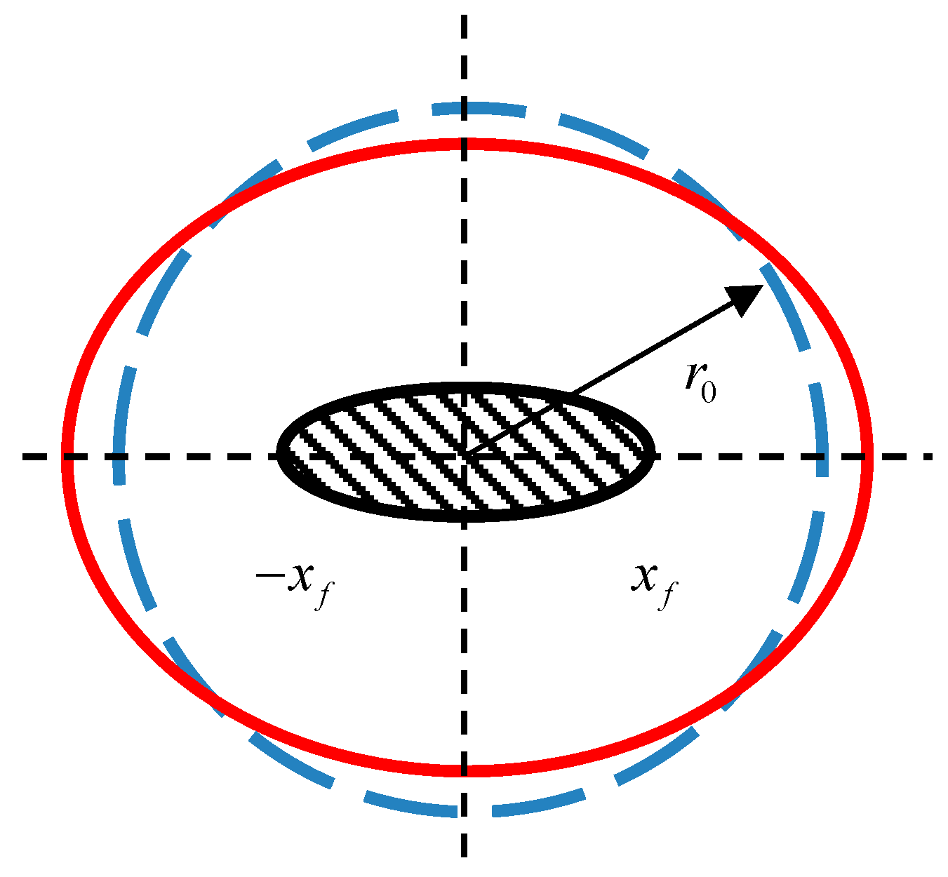
2.1.1. Establishment of Steady-State Productivity Prediction Model Based on Elliptical Fracture

Prats’s research has shown that in the seepage field of vertical fracture wells, the equipotential lines approximate ellipses (Figure 1), and the streamlines satisfy the hyperbolic equation confocal with the ellipse. Therefore, describing the physical process of seepage in vertical fracture wells using elliptic coordinates can closely approximate the actual seepage in the reservoir [13]. Thus, the elliptical fracture was used to establish a steady-state PFP prediction equation in this study.
As shown in Figure 1, considering that there is an infinite conductivity elliptical fracture in the isotropic formation with an elliptical constant-pressure outer boundary, and elliptical steady seepage occurs in the formation, and neglecting the pressure loss of fluid seepage in the fracture, the governing equation for steady-state seepage in the formation of elliptic coordinates is as follows [13,21]:
2 P ξ 2 + 2 P η 2 = 0
where P is the formation pressure, MPa, and ξ , η are radial and angular coordinates in the elliptical coordinate system.
Assuming all ellipses are confocal and equipotential (the outer boundary is an equipotential ellipse), the governing equation is simplified to
2 P ξ 2 = 0
The following pressure distribution formula can be obtained by direct integration:
P ( ξ ) = P w f + b ( ξ ξ w )
where P w f is the bottomhole pressure, MPa; ξ w is the well radius, m; and b is an undetermined coefficient.
After determining the integration constant b using the inner boundary conditions, the pressure distribution equation is obtained:
P ( ξ ) = P w f + q μ B 2 π k h ( ξ ξ w )
where q is production, m 3 / d ; μ is viscosity, mPa·s; B is the formation volume factor; k is the formation permeability, 10−3 μm2; and h is the formation thickness, m.
In a two-dimensional plane elliptic coordinate system, the Darcy’s seepage velocity equation can be written as follows [22]:
v = k μ h d s x f cos h 2 ξ cos h 2 η P ξ ξ = c
where x f is the fracture half-length, m; v is the seepage velocity, m/s.
The production equation can be obtained by integration:
q = 2 π k h Δ P w μ B ξ e = 2 π k h Δ P w μ B ln a + a 2 x f 2 x f
where ξ e is the drainage radius, m; a is the major axis of ellipse, m; and Δ P w is the production pressure difference, MPa.
Comparison with the Dupuit formula for ordinary vertical wells reveals that an infinite conductivity vertical fracture well acts equivalently to an ordinary vertical well with the well diameter r w = x f 2 .

2.1.2. Establishment of Post-Fracturing Productivity Prediction Model Considering Starting Pressure Gradient

The seepage law of LSRs no longer follows Darcy’s law, but exhibits obvious nonlinear characteristics, necessitating consideration of the impact of SPG. Therefore, the seepage motion equation for low-permeability reservoirs can be generalized as follows [23,24]:
v = K μ P 1 G P
where v is the seepage velocity, m/s, P is the pressure gradient, MPa/m, and G is the starting pressure gradient, MPa/m.
Assuming the effective height of the fracturing fracture is h i , because of the different physical properties of the reservoir layers, the fracture extends differently in each sub-layer. The fracture half-length in each sub-layer is x f i , and the fracture width is w f i . A schematic diagram of single-layer fracture parameters is shown in Figure 2. Based on the fluid flow characteristics of the fractured wells, fluid flow towards the fractured vertical well is divided into inner and outer flow fields, and the pressure at the interface P m is the pressure at the fracture tip.
The flow patterns of formation fluids after fracturing can be classified into two forms: elliptical drainage away from the vertical fracture well in the plane and linear flow of formation fluids along the fracture into the vertical well in the vertical plane. The three-dimensional flow of vertically fractured vertical wells can be simplified into two two-dimensional flows [14,15,17,25]:
(1)
Outer Flow Field (Matrix Region)
The flow in the horizontal plane for a vertical fracture well is elliptical. During well production, an ellipsoidal cylindrical surface with the wellbore as the center and the fracture endpoint as the focal point is formed. This elliptical seepage region is equivalent to a circular drainage region with a supply radius of a i + a i 2 x f i 2 / 2 and a production well diameter of x f i / 2 . Considering the influence of the SPG of low-permeability reservoirs, the following is obtained from the generalized non-Darcy law:
v = q 1 2 π r h = K μ d P d r G
The boundary conditions are
r = a i + a i 2 x f i 2 2 , P = P e ; r = x f i 2 , P = P m ;
where P e is the formation boundary pressure, MPa.
The production in the matrix region of the vertical fracture well by integration is characterized by
q Ι = 0 h q 1 d h = 0 h P e P m G i a i + a i 2 x f i 2 2 x f i 2 μ 2 π K h i ln a i + a i 2 x f i 2 x f i d h
(2)
Inner Flow Field (Fracture Region)
The flow in the vertical plane is linear along the fracture, and the following is obtained from Darcy’s law:
v = q 2 2 x f i w f i h i x f i x = K f μ d P d x
The boundary conditions are
x = 0 , P = P w ; x = x f i , P = P m ;
P w P m d P = 0 x f i q 2 μ 2 K f x f i w f i h i x f i x d x
The production in the fracture region of the vertical fracture well by integration is characterized by
q Ι Ι = 0 h P m P w μ x f i 4 K f w f i h i d h
According to the equivalent seepage resistance method, q Ι = q Ι Ι = q , and assuming that the pressures at the interface are equal, eliminating P m and considering differences in thickness, physical properties and fracture morphology, the productivity prediction formula for a vertically fractured vertical well in a low-permeability reservoir considering the SPG is as follows:
q = 0 h P e P w G i a i + a i 2 x f i 2 2 x f i 2 μ 2 π K h i ln a i + a i 2 x f i 2 x f i + μ x f i 4 K f w f h i d h

2.1.3. Establishment of Post-Fracturing Productivity Prediction Model Considering Oil-Water Two-Phase Flow

If the formation involves two-phase or even multi-phase flow, the other conditions remain unchanged in the formula, except for K, i.e., permeability. The relative permeabilities of the oil phase and water phase were introduced to characterize two-phase flow and were substituted into the PFP formula, yielding the PFP formula for oil–water two-phase flow considering SPG [26,27,28]:
q o i l = 0 h P e P w G i ( a i + a i 2 x f i 2 2 x f i 2 ) μ o 2 π K · K r o h i l n a i + a i 2 x f i 2 x f i + μ o · x f i 4 K f · w f h i d h
q w a t e r = 0 h P e P w G i ( a i + a i 2 x f i 2 2 x f i 2 ) μ w 2 π K · K r w h i l n a i + a i 2 x f i 2 x f i + μ w · x f i 4 K f · w f h i
where q o i l is oil productivity, q w a t e r is water productivity; Kro is oil phase relative permeability, 10−3 μm2; and Krw is water phase relative permeability, 10−3 μm2.

2.2. Basic Parameter Calculation for Post-Fracturing Productivity Model

2.2.1. Starting Pressure Gradient

The typical seepage law curve for low-permeability porous media is shown in Figure 3 [29]. It can be observed that, during the low-velocity seepage stage, when the driving pressure gradient is relatively small, the seepage curve exhibits nonlinear characteristics (as indicated by segment ad in the figure): as the pressure gradient increases, the curve gradually transitions to linearity, eventually reaching a linear segment (such as segment de). Here, a represents the true SPG, i.e., the SPG when fluid flows through the largest pore channels in the porous medium; c represents the pseudo SPG, and b represents the minimum pressure gradient required for fluid flow in the smallest pore channels. The “pressure difference-flow rate” method is used to determine the SPG of the core.
From Equation (7), it can be seen that when Δ P < G , the driving force of the fluid is insufficient to overcome the resistance to fluid flow, and the fluid cannot flow. Fluid flow occurs only when Δ P > G . As the driving pressure gradient increases, the influence of the SPG gradually diminishes. Therefore, within a relatively high pressure gradient range, the liquid seepage velocity and pressure gradient form a straight line that does not pass through the origin of the coordinates, which can be mathematically described as follows:
v = a Δ P b   ( Δ P > G )
where a and b are the coefficient and constant term of the straight line, respectively, representing the slope of the seepage curve and the intercept on the velocity axis, with a > 0 and b ≥ 0. Based on the correspondence between the above two equations, we have the following
a = K μ
b = K μ G
G = b ( K μ ) 1
Equation (21) indicates that the SPG in low-permeability reservoirs has a hyperbolic inverse relationship with fluid mobility. The product of these two is a constant that relates only to the physical properties of the reservoir and the properties of the fluid passing through. For the same seepage fluid, both fluid properties and rock petrophysical properties are constant, with the only difference being the core permeability. Thus,
lg G = lg K + lg ( b μ )
The SPG is inversely proportional to reservoir permeability. In a double logarithmic coordinate system, the relationship between them is a straight line with a slope of −1. Using experimental data on the SPG of 24 cores from the study area, a cross-plot of gas permeability and oil-phase SPG was established in a double logarithmic coordinate system (Figure 4), yielding the following relational expression:
G = 0.0682 K 0.9815
This experimentally verifies the correctness of the mathematical representation of the SPG.

2.2.2. Calculation of Fracturing Fracture Parameters

Fracture Length

The fracture length is determined using the volume balance method. If the volume of fluid flowing into each wing of the fracture at any time per unit time is known, the fracture height and fracture width (assumed to be constant here, the same principle applies to the variable height calculation equation) and the fluid volume balance variable are used together to determine the fracture length.
Following the Nordgren principle [30], the dimensionless variables below are introduced:
t D = 16 π 2 2 C 5 h G 1 ν μ i 2 2 / 3 t
x D = 16 π 2 2 C 8 h 4 G 1 ν μ i 5 1 / 3 x
w D = C 2 h G 4 1 ν μ i 2 1 / 3 w max
where t D is the dimensionless production time; x D is the dimensionless distance from the wellbore; w D is the dimensionless dynamic fracture width. i is the displacement of the hydraulic pressure pump, m 3 / s ; C is the fluid filtrate loss coefficient, m/ m i n 1 / 2 ; G is the shear modulus, G P a ; and ν is Poisson’s ratio. t is the production time, s; x is the distance from the wellbore, m; and w m a x is the maximum fracture width, mm.
Using these equations composed of dimensionless variables, the volume balance equation for fluid in the fracture volume element is
2 w D 4 x D 2 = 1 t D τ D + w D t
where τ D is the dimensionless filtrate loss time.
For low-porosity, low-permeability reservoirs, if fluid loss is neglected, Equation (29) is simplified to
2 w D 4 x D 2 = w D t D
The constrained boundary conditions are
w D 4 x D = 1   ( x D = 0 )
w ¯ D = 0   ( x D = L D )
2 w D 4 x D = 1   ( x D = L D )
where L D is the dimensionless fracture half-length.
The boundary conditions for Equation (28) (Equations (29)–(31)) represent a complete formulation of this problem. Solving these equations yields the dynamic geometric shape parameters of the fracture. Nordgren has numerically solved this set of equations (Figure 5) [30]:
L D = 1.32 t D 4 / 5
The above equation is converted into dimensional terms:
L = 0.44 G i 3 h 4 1 ν μ 1 / 5 t 4 / 5
where L is the fracture half-length, m.

Fracture Permeability

The ultimate permeability of fractures is a function of the proppant diameter used in fracturing operations. According to the Blake–Kozeny equation [31], it is expressed as
K f = d p 2 ϕ f 3 150 1 ϕ f 2
where K f is the fracture permeability, μ m 2 ; d p is the proppant diameter, mm; and ϕ f is the porosity of the multi-layer proppant pack, %.
The US petroleum industry defines the proppant diameter, which is classified by the mesh standard sieve analysis method. Table 1 provides information on the sieve diameter and the corresponding porosity of the proppant pack for graded sand. Based on this information, the fracture permeability can be calculated using Equation (34).

Fracture Width

The ultimate width of a fracturing fracture is directly related to the proppant content on the fracture surface when the fracture closes [32]:
Γ s = w f ( 1 ϕ f ) ρ b
where ϕ f is the ultimate porosity of the proppant, %;
ρ b is the density of the proppant, k g / c m 3 ;
w f is the ultimate width of the fracturing fracture, mm;
Γ s is the proppant content on the fracture surface, k g / m 2 .
Assuming the total mass of proppant injected during fracturing is M 0 , the height of the fracture is h, and the length of the fracture is L f , the concentration of proppant on the fracturing fracture surface is
Γ s = M 0 2 h L f
where M 0 is the mass of proppant, k g ; L f is fracture half-length, m.
Combining Equations (37) and (38), the ultimate fracture width can be obtained:
𝑤 f = M 0 2 h L f ( 1 ϕ f ) ρ b

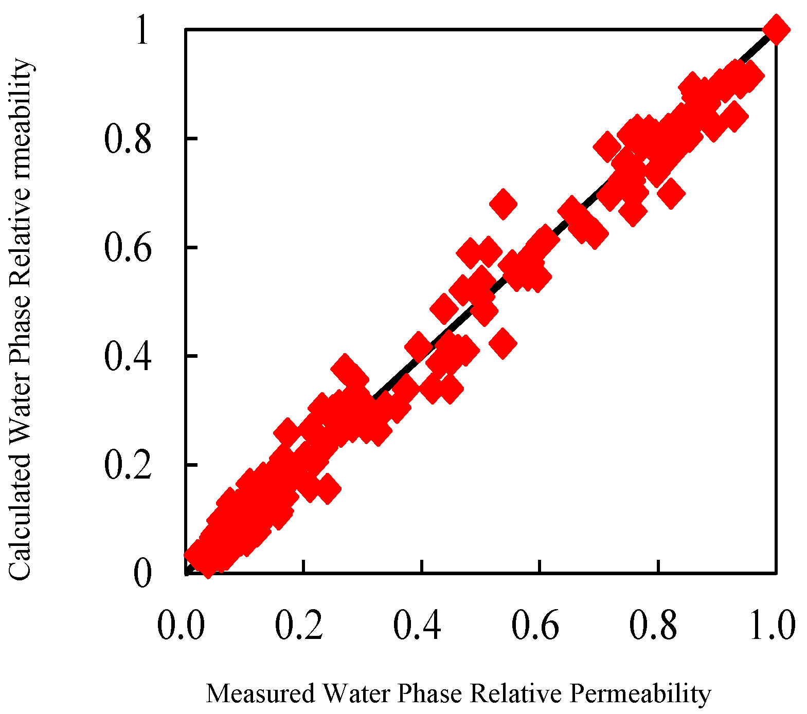
2.2.3. Calculation of Relative Permeability

Calculation of Oil–Water Two-Phase Relative Permeability

In practical applications of the modified Brooks–Corey model, there may be a significant discrepancy between the individually fitted phase permeability data and the experimental data. Although the overall error for the water phase is relatively small, the error in fitted data points increases as the water saturation increases. Similarly, for the oil phase, the calculated value of relative permeability differs greatly from the experimental measurement data, and especially at a lower water saturation, the error in the fitted oil phase data points increases. Therefore, improvements are needed in the water phase exponent in the classic relative permeability and water saturation calculation formula. After repeated fitting and calculations, and through comparative analysis, the Li Kewen model was selected for this study due to its higher calculation accuracy. The calculation expressions for relative permeability of water and oil phases in this model are as follows [33]:
K r w = K r w ( S o r ) ( S w n + a S w ) 1 + a
K r o = K r o ( S w i ) ( 1 S w ) m + b ( 1 S w ) 1 + b
where
S w = S w S w i 1 S w i S o r
where Sw is the water saturation (as a decimal), Swi is the irreducible water saturation (as a decimal), Sor is the residual oil saturation (as a decimal), Krw(Sor) is the water phase relative permeability at residual oil saturation and Krw is the water phase relative permeability. n and a are parameters for the water phase relative permeability model; m and b are parameters for the oil phase relative permeability model.

Determination of Model Parameters

The parameter values n, a, m and b in the Li Kewen model were optimized using 30 phase permeability experimental samples from the study area. Through multivariate nonlinear regression, the calculation formulas for the model parameters n, a, m and b are obtained as follows:
n = 2 . 154644 ϕ 1 . 8857 + 0 . 904118 K 0 . 2234 0 . 32001
a = 2 . 780133 ϕ 2 . 4439 + 0 . 112356 K 0 . 2958 + 0 . 036802
m = 8 . 97273 ϕ + 3 . 626687 K 0 . 072 + 3 . 548104
b = 0 . 969391 ϕ + 0 . 362217 K 0 . 076 0 . 02719
The average relative errors of the model parameters n, a, m and b calculated using the above formulas are 21.9%, 50.2%, 7.7% and 12.4%, respectively. Using the obtained calculation formulas for parameters n, a, m and b, along with the model forms for water and oil phase relative permeability, the average relative errors between the calculated and measured values for the water and oil phases’ relative permeability are 12.1% and 8.8%, respectively (Figure 6 and Figure 7).

3. Results

The post-fracturing oil productivity prediction formula for two-phase flow based on elliptical fractures was applied to predict the post-fracturing oil production of 111 pay horizons in 34 fractured wells in the Sa and Pu oil layers of the Daqing Oilfield. Based on post-fracturing oil production, the relative error in productivity was used as the control criterion, i.e., the larger the productivity base, the higher the required accuracy of relative error control (Table 2). The conformity rate of the productivity calculation was quantitatively determined. The calculation results were compared and analyzed with the oil testing results, as shown in Figure 8. A total of 86 horizons matched the oil production level in the oil testing, with a conformity rate of 77.5%. The post-fracturing water productivity prediction formula for two-phase flow based on elliptical fractures was applied to predict the post-fracturing water production of 56 water-producing horizons in 20 fractured wells in the study area. Based on the post-fracturing water production, the relative error in productivity was used as the control criterion. The calculation results were compared and analyzed with the oil testing results, as shown in Figure 8. A total of 41 horizons matched the water production level in the oil testing, with a conformity rate of 73.2%, as shown in Figure 9. This fully demonstrates the correctness, effectiveness and practicality of the PFP prediction model for oil-water two-phase flow established in this paper.

4. Discussion

The study area has high-quality petroleum with a density range of 0.685–0.854 g/cm3 (average 0.752 g/cm3) and a viscosity distribution between 1.43 and 7.85 mPa·s (average 4.3 mPa·s), showing minimal variability in oil quality across different wells. The proposed method in this paper is therefore suitable for PFP evaluation of low-viscosity thin oil reservoirs. However, it is also applicable to heavy oil reservoirs with non-Newtonian fluid, where the SPG incorporates both low porosity-permeability reservoir characteristics and Bingham fluid rheological properties.
Vertical wells are universally adopted for drilling and production in the mid-shallow formations of the study area, which hold significant economic appeal for conventional reservoirs in mature oilfields and represent the primary drilling method for conventional reservoirs in the future. Most mature oilfields employ fracturing stimulation to enhance reservoir flow properties and increase single-well production from LSRs. This method was developed against such a background. While the research focuses on vertically fractured wells, its application can be extended to highly deviated wells and horizontally fractured wells. Some pioneering studies in this direction have already been conducted [34,35], which will be prioritized as our research focus in subsequent stages.
LSRs exhibit complex pore structures, strong heterogeneity and large permeability variations. For some high-permeability reservoirs, neglecting fracturing fluid filtrate loss during fracture length calculation may introduce errors, thereby reducing the conformity rate of productivity prediction. A reservoir quality index (RQI)-based classification scheme will be adopted in future research to improve the calculation precision of permeability, water saturation and oil-water relative permeability. Upon reservoir classification, we will develop fracture length calculation methods that either consider or disregard fracturing fluid filtrate loss for different reservoir types, thereby enhancing the calculation accuracy of fracture length and fracture width.

5. Conclusions

(1)
By applying the linear flow seepage formula for elliptical fractures and considering the influence of the SPG in low-permeability reservoirs, a theoretical model for predicting the PFP of oil–water two-phase flow was established. Through the interpretation and verification of the productivity of 111 small horizons in 34 actual wells, the conformity rate for oil production was 77.5%, and the conformity rate for water production was 73.2%, with an improvement of over 15% in the interpretation conformity rate. Compared with actual well test productivity, the mean absolute error of oil productivity prediction is 3.51 t/d, and the mean absolute error of water productivity prediction is 12.37 t/d, which can fully meet the evaluation requirements for field PFP prediction.
(2)
Using formation parameters, logging parameters and fracturing operation parameters, formulas were established for calculating basic parameters such as fracture length, fracture width and fracture permeability. The results of processing actual well data indicate that these basic parameters can meet the accuracy requirements for quantitative productivity prediction.
(3)
By introducing an empirical coefficient and improving the empirical relationship between relative permeability and saturation, a model for the relationship between relative permeability and saturation was established. Using experimental data from simultaneous relative permeability and resistivity measurements as well as supporting experimental data, formulas for calculating each parameter in the model were provided, which improved the accuracy of calculating the relative permeability of oil and water in the reservoir.

Author Contributions

Conceptualization, H.W. and X.L.; methodology, X.H.; software, B.X. and X.H; validation, H.W., X.L. and Q.S.; formal analysis, H.W.; investigation, X.L.; resources, Q.S.; data curation, B.X.; writing—original draft preparation, H.W. and X.L.; writing—review and editing, H.W. and X.L.; visualization, C.W.; supervision, Q.S.; project administration, C.W.; funding acquisition, H.W. All authors have read and agreed to the published version of the manuscript.

Funding

This work was supported by the Hainan Province Science and Technology Special Fund (No. ZDYF2024GXJS015).

Data Availability Statement

The data are not publicly available due to privacy.

Acknowledgments

We thank all graduate research assistants who helped with data collection.

Conflicts of Interest

Author Xuchao He was employed by the company Fangxing Company of Daqing Oilfield. The remaining authors declare that the research was conducted in the absence of any commercial or financial relationships that could be construed as a potential conflict of interest.

References

  1. Li, X.Y.; Wan, Q.S.; Wang, F.L. Interpretation method of oil-water layer in low oil-saturation reservoirs: A case study in Putaohua reservoirs in Gu628 Block of Xinzhao Oilfield. J. Prog. Geophys. 2021, 36, 1088–1094. (In Chinese) [Google Scholar]
  2. He, A.T.; Yan, J.P.; Huang, L.S. Oil heterogeneity characteristics of low oil saturation sandstone reservoirs in M area of junggar basin. J. Well Logg. Technol. 2023, 47, 476–485. (In Chinese) [Google Scholar]
  3. Xu, X.C. Genesis of low oil-saturated reservoir of Putaohua oil layer in Gulong Sag. J. Fault Bl. Oil Gas Fld. 2017, 24, 320–323. (In Chinese) [Google Scholar]
  4. Liu, G.Q.; Yuan, C. Refined log evaluation method for recoverable reserves and production enhancement on low saturation oil-bearing reservoirs. J. World Pet. Ind. 2025, 32, 27–42. (In Chinese) [Google Scholar]
  5. Zou, C.N.; Zhu, R.K.; Wu, S.T. Types, characteristics, genesis and prospect of conventional and unconventional hydrocarbon accumulations: Taking tight oil and tight gas in China as an instance. J. Acta Pet. Sin. 2012, 33, 173–187. (In Chinese) [Google Scholar]
  6. Ji, T.L.; Lu, S.F.; Tang, M.M. Productivity predicting method of the fractured horizontal wells in the tight oil reservoirs. J. Daqing Pet. Geol. Dev. 2016, 35, 165–169. (In Chinese) [Google Scholar]
  7. Liu, K.; Sun, J.M.; Wang, Y. Tight oil reservoir productivity prediction after fracturing in horizontal wells. J. Sci. Technol. Eng. 2017, 35, 165–169. (In Chinese) [Google Scholar]
  8. Zhang, L.H.; Pan, B.Z.; Zhuang, H. Productivity log forecasting method for Post-frac reservoir with low porosity and low permeability. J. Well Logg. Technol. 2012, 36, 101–105. (In Chinese) [Google Scholar]
  9. Guo, J.C.; Liu, H.; Zeng, F.H. Influence of varying fracture width on fractured wells long-term productivity. J. China Univ. Pet. 2015, 39, 111–115. (In Chinese) [Google Scholar]
  10. Xiong, J.; Yu, L.J.; Guo, P. Analysis on productivity equation of fractured well in low permeability gas reservoir with Non-Linear seepage. J. Nat. Gas Oil. 2012, 30, 42–45+4. (In Chinese) [Google Scholar]
  11. He, Y.F.; Xu, L.Y.; Lu, W.Y. Productivity analysis of fractured well in low permeability gas reservoir. J. Spec. Oil Gas Reserv. 2006, 13, 59–61+107. (In Chinese) [Google Scholar]
  12. Yin, H.J.; Liu, Y.; Fu, C.Q. Productive analysis of fractured well in low permeability reservoir. J. Xinjiang Pet. Geol. 2005, 26, 285–287. (In Chinese) [Google Scholar]
  13. Prats, M. Effect of vertical fractures on reservoir behavior incompressible fluid case. In Proceedings of the 35th Annual Fall Meeting of SPE, Denver, CO, USA, 2–5 October 1960. [Google Scholar]
  14. Raymond, L.R.; Binder, G.G., Jr. Productivity of wells in vertically fractured damaged formations. J. Pet. Technol. 1967, 19, 120–130. [Google Scholar]
  15. Agarwal, R.G.; Carter, R.D.; Pollock, C.B. Evaluation and performance prediction of low-permeability gas wells stimulated by massive hydraulic fracturing. J. Pet. Technol. 1979, 31, 362–372. [Google Scholar]
  16. Mao, C.H.; Huang, F.S.; Hu, Q.J. Optimization simulation of hydraulic fracture parameters for highly deviated wells in tight oil reservoirs, based on the reservoir fracture productivity coupling model. Processes 2024, 12, 179. [Google Scholar] [CrossRef]
  17. Poe, B.D. Production performance evaluation of hydraulically fractured wells. In Proceedings of the 2000 SPE/CERI Gas Technology Symposium, Calgary, AB, Canada, 3–5 April 2000. [Google Scholar]
  18. Wu, M.L.; Zhu, J.M.; Li, L.L. Calculation of perforated vertical and horizontal well productivity in low-permeablility reservoirs. SPE Drill. Compl. 2019, 35, 218–236. [Google Scholar]
  19. Zhao, Y.L.; Zhang, L.H.; He, Z.X. Productivity for horizontal wells in low permeability reservoir with oil/water two-phase flow. Math. Probl. Eng. 2014, 14, 364678. [Google Scholar]
  20. Sun, Y.T.; Wang, J.W.; Wang, T. Post-Fracture production prediction with production segmentation and well logging: Harnessing pipelines and hyperparameter tuning with GridSearchCV. Appl. Sci. 2024, 14, 3954. [Google Scholar] [CrossRef]
  21. Jiang, T.X.; Shan, W.W.; Yang, Y.L. The calculation of stable production capability of vertical fracture well. J. Pet. Explor. Dev. 2001, 28, 61–63. (In Chinese) [Google Scholar]
  22. Zhang, J.Q.; Lei, X.; Zhang, Q.L. Productivity evaluation of water-producing fractured horizontal wells in low permeability gas reservoir. Nat. Gas Geosci. 2019, 30, 1701–1708. (In Chinese) [Google Scholar]
  23. Li, S.Q.; Cheng, L.S.; Li, X.S. Non-linear seepage flow models of ultra-low permeability reservoirs. J. Pet. Explor. Dev. 2008, 35, 606–612. (In Chinese) [Google Scholar]
  24. Deng, Y.E.; Liu, C.Q. Theory of oil water flow through porous media and calculation of development indexes with starting pressure gradient included. J. Explor. Dev. 1998, 25, 36–39. (In Chinese) [Google Scholar]
  25. McGuire, W.J.; Sikora, V.J. The effect of vertical fractures on well productivity. J. Pet. Technol. 1960, 12, 72–74. [Google Scholar]
  26. Wang, R. Fracturing well productivity of low permeability reservoir with taking the oil-water two phase flow into consideration. J. Reserv. Eval. Dev. 2021, 11, 60–765. (In Chinese) [Google Scholar]
  27. Huang, S.J.; Hou, D.L.; Qiang, X.Y. A new method for evaluating the gas-water two-phase productivity of fractured straight wells in tight sandstone gas reservoirs. J. Unconv. Oil Gas. 2023, 10, 68–74. (In Chinese) [Google Scholar]
  28. Deng, M.Z.; Niu, N.; Yin, S. Gas-water two-phase productivity prediction model of multistage fractured horizontal wells in anisotropic tight sandstone gas reservoirs. J. Pet. Geol. Recovery Effic. 2024, 31, 99–111. (In Chinese) [Google Scholar]
  29. Mohan, J. Effect of non-Dracy flow on well productivity for hydraulically fractured gas-condensate well. In Proceedings of the 2006 Annual Technical Conference and Exhibition, San Antonio, TX, USA, 24–27 September 2006. [Google Scholar]
  30. Nordgren, R.P. Propagation of a vertical hydraulic fracture. In Proceedings of the SPE 45th Annual Fall Meeting, Houston, TX, USA, 4–7 October 1970. [Google Scholar]
  31. Bird, R.B.; Stewart, W.E.; Lightfoot, E.N. Transport Phenomena; John Wiley & Sons: Hoboken, NJ, USA, 1960. [Google Scholar]
  32. Nolte, K.G. Determination of fracture parameters for fracturing pressure decline. In Proceedings of the 54th Annual Fall Technical Conference and Exhibition of the Society of Petroleum Engineers, Las Vegas, NV, USA, 23–25 September 1979. [Google Scholar]
  33. Li, K.W. An optimistic method for calculating oil-water relative permeability curves from dynamic displacement experimental data. J. Jianghan Pet. Inst. 1989, 11, 48–49. (In Chinese) [Google Scholar]
  34. Gao, Y.F.; Yang, D.; Han, H. Productivity evaluation modeling by numerical simulation for shale gas with variable dynamic viscosity in fractured horizontal wells. Processes. 2025, 13, 119. [Google Scholar]
  35. Zeng, J.; Wang, X.Z.; Guo, J.C. Composite linear flow model for multi-fractured horizontal wells in tight sand reservoirs with threshold pressure gradient. J. Pet. Sci. Eng. 2018, 165, 890–912. [Google Scholar]
Figure 1. Physical model of elliptical seepage.
Processes 13 01091 g001
Figure 2. Vertical fracture in a fractured vertical well.
Processes 13 01091 g002
Figure 3. Schematic diagram of typical seepage law curve for low-permeability porous media.
Processes 13 01091 g003
Figure 4. Cross-plot of starting pressure gradient and permeability.
Processes 13 01091 g004
Figure 5. Dimensionless fracture length [25] as a function of dimensionless time.
Processes 13 01091 g005
Figure 6. Comparison of calculated and measured values of water phase relative permeability.
Processes 13 01091 g006
Figure 7. Comparison of calculated and measured values of oil phase relative permeability.
Processes 13 01091 g007
Figure 8. Comparison of oil production predicted based on the seepage formula method with oil testing results.
Processes 13 01091 g008
Figure 9. Comparison of water production predicted based on the seepage formula method with oil testing results.
Processes 13 01091 g009
Table 1. Properties of commercially available graded sand.
SizeRange (Mesh)8~1210~2010~3020~4040~6010~20
Sieve Diameter (mm)2.38~1.682.00~0.842.00~0.5890.84~0.420.42~0.2502.00~0.84
Approximate Permeability (μm2)172232118811944321
Porosity (%)363232353232
Table 2. Productivity accuracy overview based on relative error control.
Oil Testing Productivity Base (t/d)Control Relative Error (%)Productivity
Lower Limit (t/d)
Productivity
Upper Limit (t/d)
Description
1003070130The productivity within the lower and upper limits matches the oil testing productivity base.
50502575The productivity within the lower and upper limits matches the oil testing productivity base.
2070634The productivity within the lower and upper limits matches the oil testing productivity base.
1080218The productivity within the lower and upper limits matches the oil testing productivity base.
11000.132The productivity within the lower and upper limits matches the oil testing productivity base.
<1 0<1The order of magnitude matches while considering both the lower and upper limits of productivity.
Disclaimer/Publisher’s Note: The statements, opinions and data contained in all publications are solely those of the individual author(s) and contributor(s) and not of MDPI and/or the editor(s). MDPI and/or the editor(s) disclaim responsibility for any injury to people or property resulting from any ideas, methods, instructions or products referred to in the content.

