

Comparative Electrochemical Performance of Solid Oxide Fuel Cells: Hydrogen vs. Ammonia Fuels—A Mini Review


Abstract
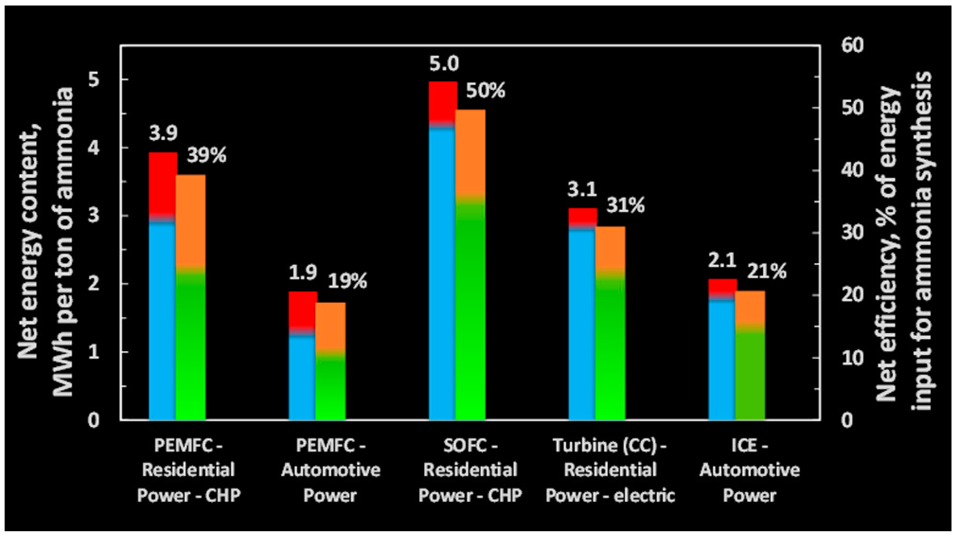
1. Introduction
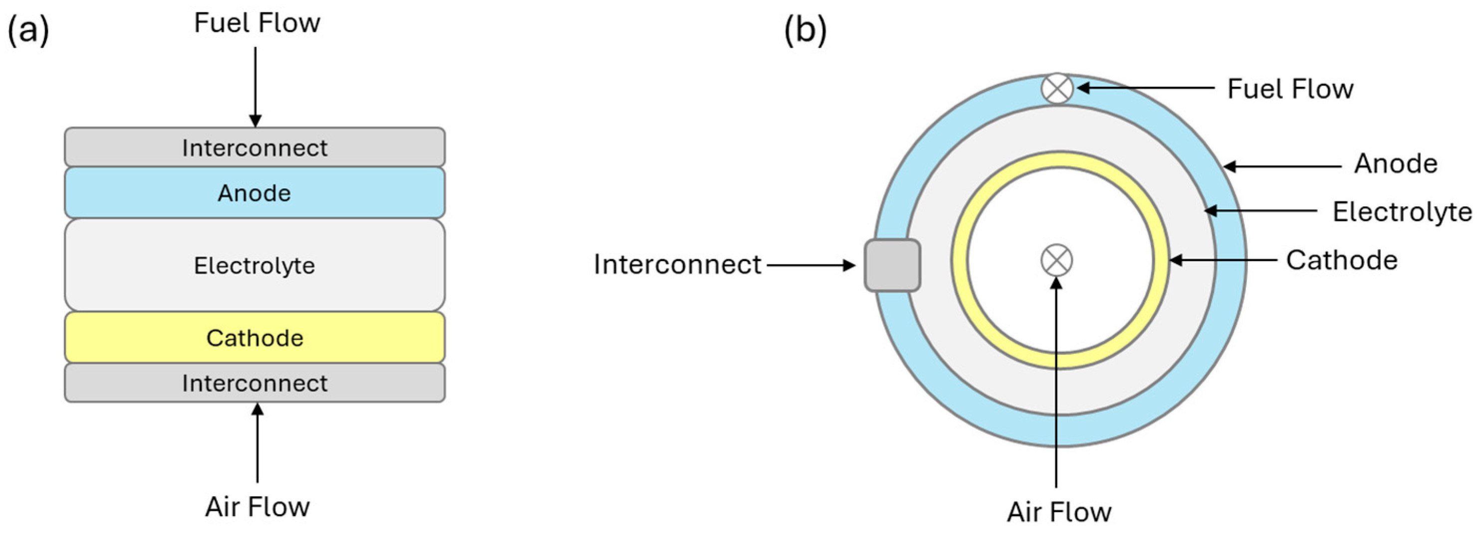
2. Solid Oxide Fuel Cells
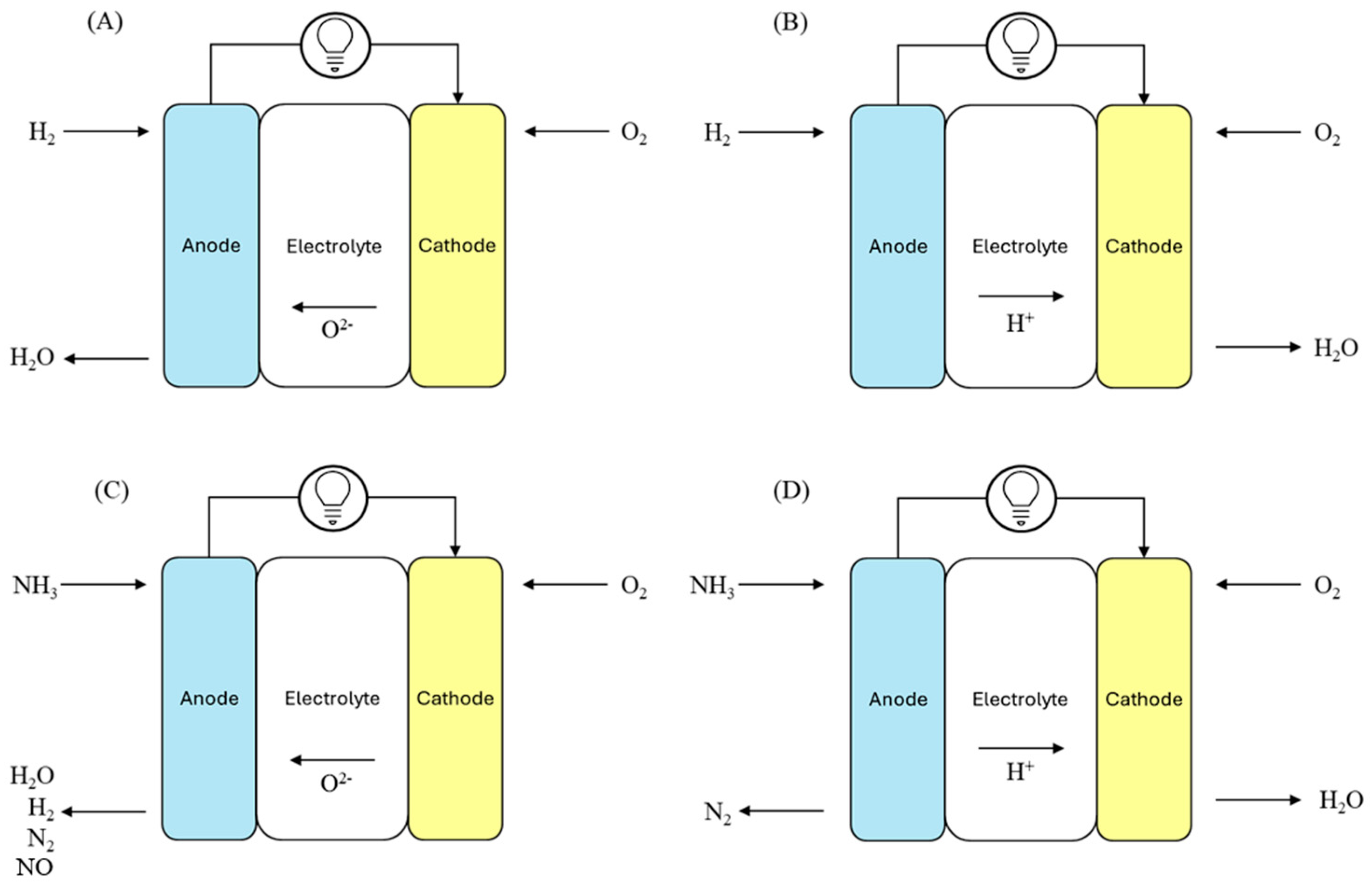
2.1. O-SOFCs and H-SOFCs
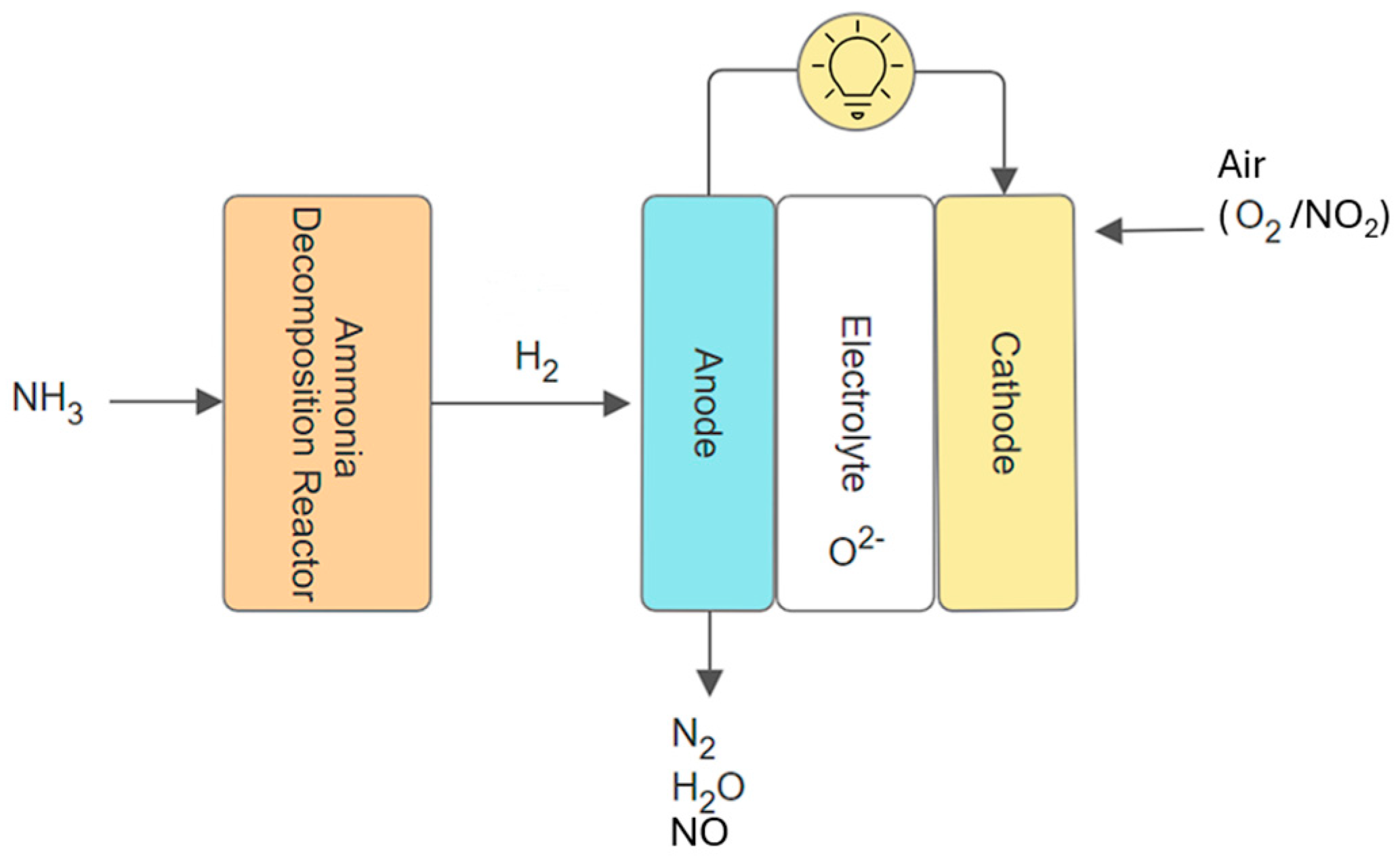
2.2. Direct and Indirect SOFC Under Ammonia Fuel
3. SOFC Parameters Under Ammonia and Hydrogen Fuels
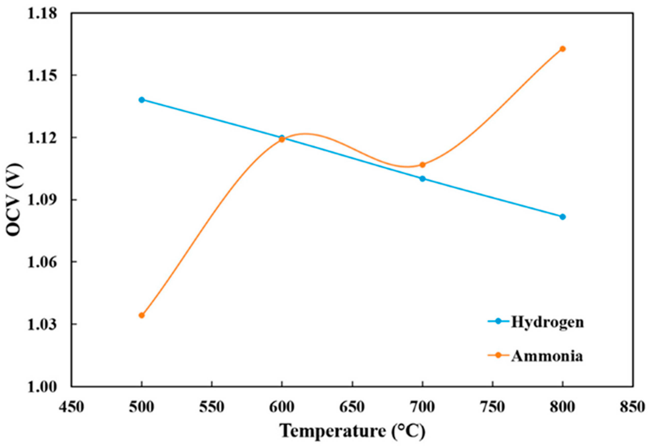
3.1. Open-Circuit Voltage (OCV)
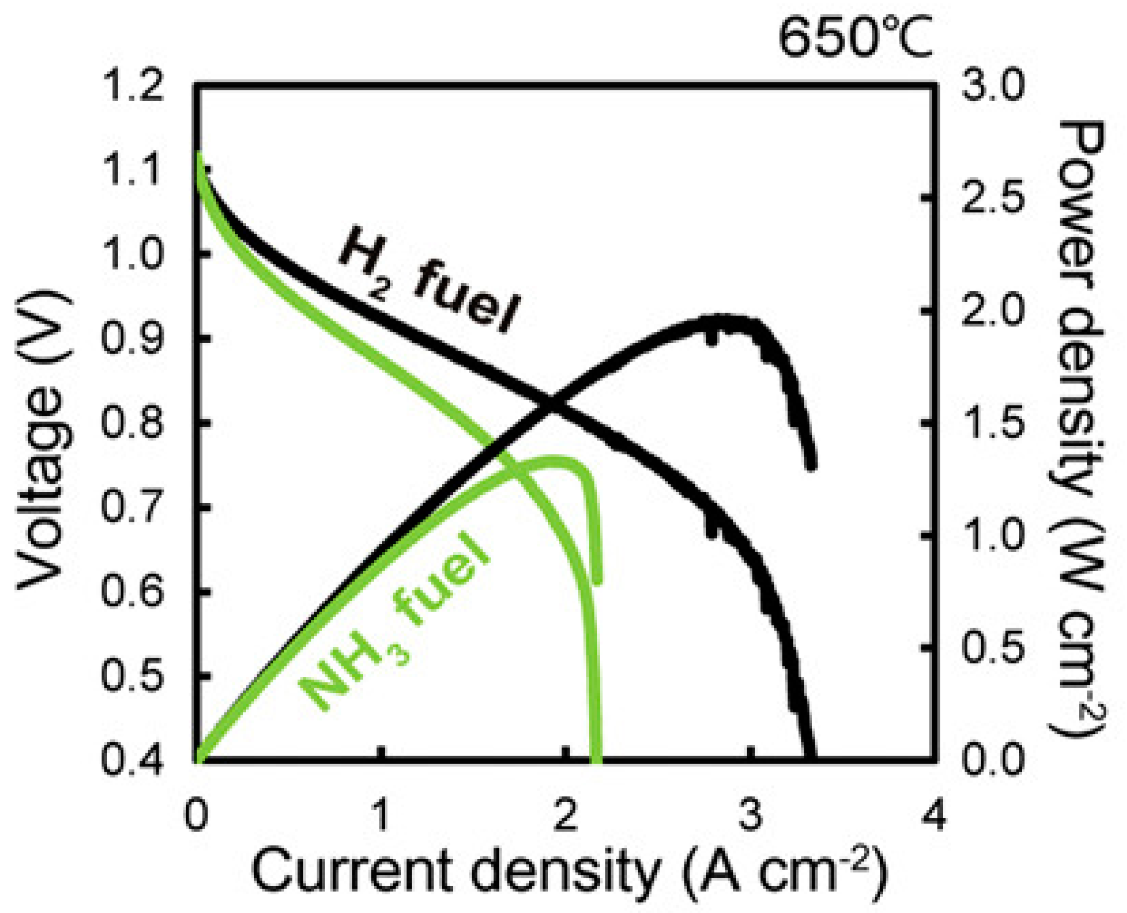
3.2. Power Density
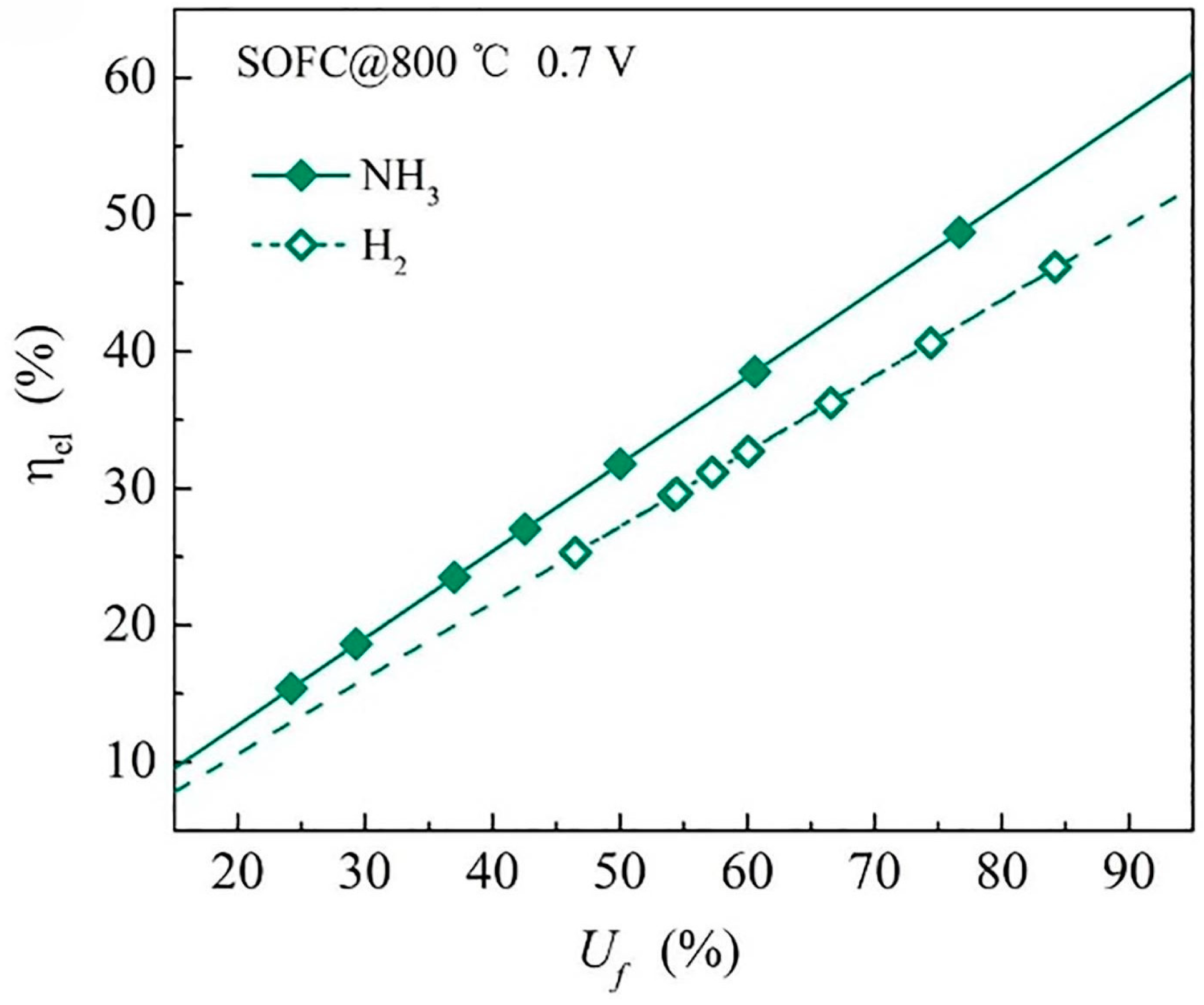
3.3. Fuel Utilisation
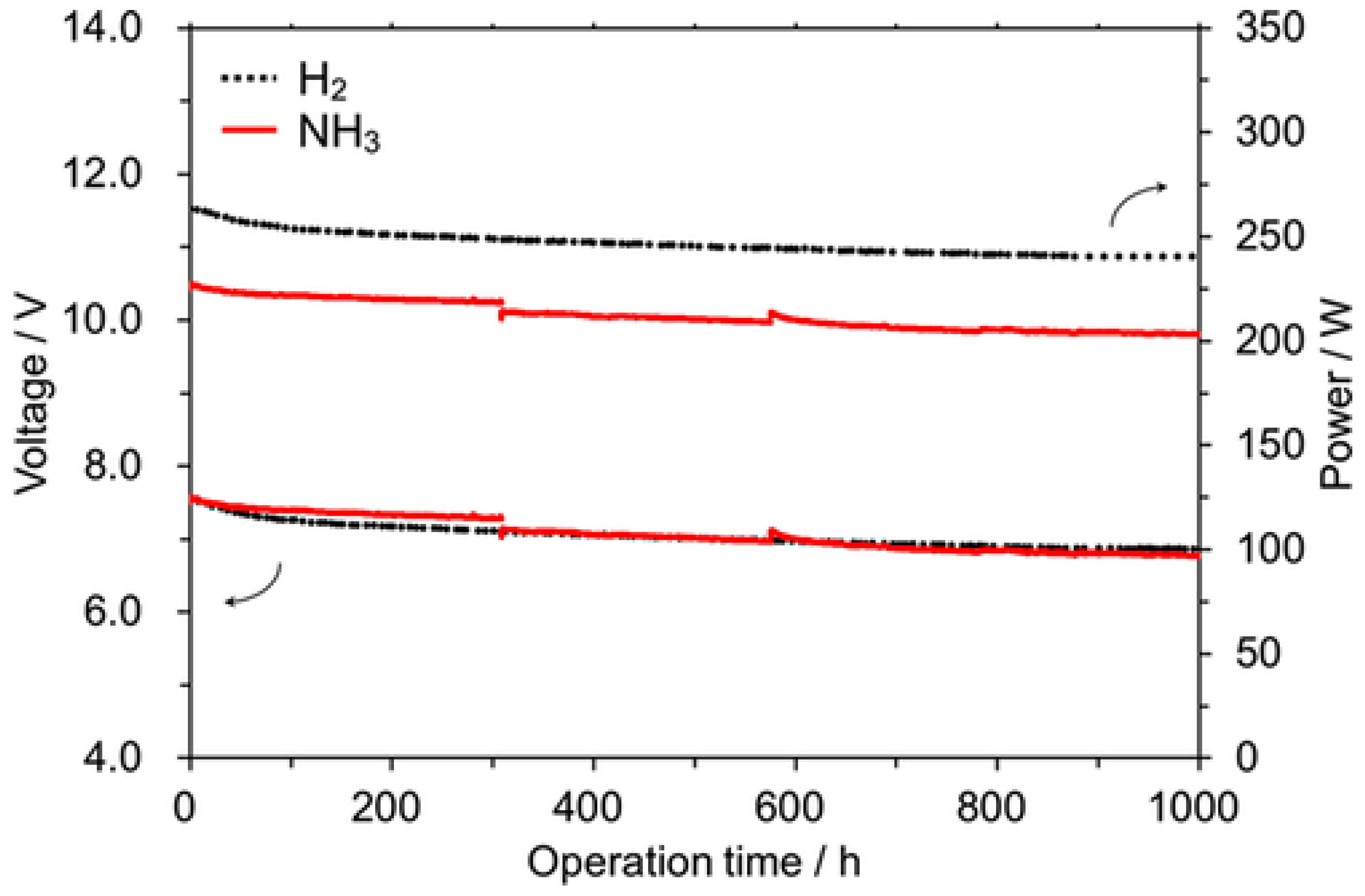
3.4. Stability
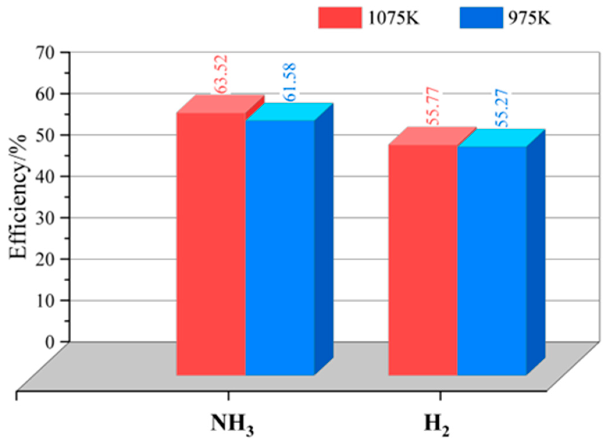
3.5. Electrical Efficiency
3.6. Electrochemical Impedance Spectroscopy
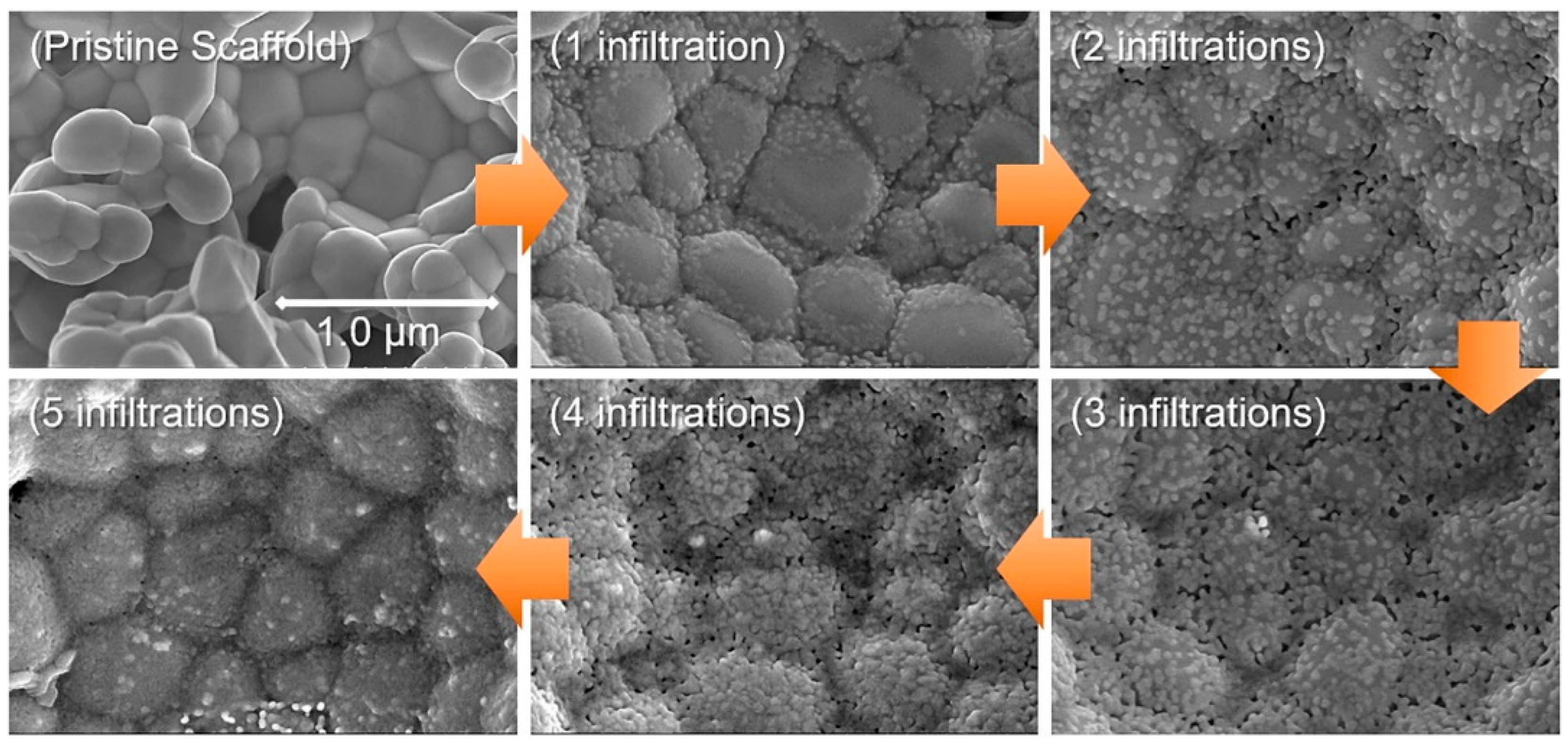
4. Strategies and Advances for SOFC Cell Materials Fabrication

| Deposition Technique | Thickness of Film (μm) | Ref. |
|---|---|---|
| Pulsed laser deposition | 60–150 μm | [37,61] |
| Spin coating (colloidal) | 30–100 nm | [62] |
| Dip coating (colloidal) | 25–200 μm | [63] |
| Screen printing (colloidal) | 10–200 μm | [64] |
| Electrophoretic deposition (EPD) | 1–200 μm | [61] |
| Tape casting | 10–1500 μm | [64] |
| Dry pressing | 1–100 μm | [63] |
4.1. Anode
4.2. Cathode
4.3. Electrolytes
5. H2 and NH3 Fuel SOFC: Operating Characteristics
5.1. Operating Temperature
5.2. Round-Trip Efficiency
5.3. SOFC Stack
6. Conclusions and Future Directions
Author Contributions
Funding
Data Availability Statement
Acknowledgments
Conflicts of Interest
References
- Alrikabi, N. Renewable Energy Types. J. Clean Energy Technol. 2014, 2, 61–64. [Google Scholar] [CrossRef]
- Ergun, S.; Dik, A.; Boukhanouf, R.; Omer, S. Large-Scale Renewable Energy Integration: Tackling Technical Obstacles and Exploring Energy Storage Innovations. Sustainability 2025, 17, 1311. [Google Scholar] [CrossRef]
- Biswas, S.; Dhawale, D.S.; Hosseini, T.; Kaur, G.; Giddey, S.; Haque, N. A Review on Critical Metals Used in Solid Oxide Cells for Power ↔ X Applications and Materials Recyclability. ACS Sustain. Chem. Eng. 2024, 12, 6037–6058. [Google Scholar] [CrossRef]
- Zarabi Golkhatmi, S.; Asghar, M.I.; Lund, P.D. A review on solid oxide fuel cell durability: Latest progress, mechanisms, and study tools. Renew. Sustain. Energy Rev. 2022, 161, 112339. [Google Scholar] [CrossRef]
- Ritchie, H.; Rosado, P.; Roser, M. Greenhouse gas emissions. Our World Data 2020. Available online: https://ourworldindata.org/greenhouse-gas-emissions (accessed on 3 April 2025).
- Nkounga, W.; Ndiaye, M.; Ndiaye, M. Management of Intermittent Solar and Wind Energy Resources: Storage and Grid Stabilization. In Sustainable Energy Access for Communities; Springer: Cham, Switzerland, 2022; p. 109. [Google Scholar] [CrossRef]
- Schäffer, L.E.; Korpås, M.; Bakken, T.H. Implications of environmental constraints in hydropower scheduling for a power system with limited grid and reserve capacity. Energy Syst. 2023, 14, 1–43. [Google Scholar] [CrossRef]
- Wang, Z.; Zhao, F.; Ma, Y.; Xia, R.; Han, F. Performance Analysis and Design of Direct Ammonia Fuel Tubular Solid Oxide Fuel Cell for Shipborne Unmanned Aerial Vehicles. Aerospace 2023, 10, 397. [Google Scholar] [CrossRef]
- Sebbani, I.; Ettouhami, M.K.; Boulakhbar, M. Fuel cells: A technical, environmental, and economic outlook. Clean. Energy Syst. 2025, 10, 100168. [Google Scholar] [CrossRef]
- Gao, Y.; Yao, W.; Wang, J.; Cui, Z. Thermodynamic analysis of solid oxide fuel cell based combined cooling, heating, and power system integrated with solar-assisted electrolytic cell. J. Therm. Sci. 2023, 32, 93–108. [Google Scholar] [CrossRef]
- Elmutasim, O.; Giddey, S.; Dhawale, D.S.; Bhattacharya, S. Ammonia to power: Advancing direct ammonia solid oxide fuel cells through experimental and theoretical studies. Int. J. Hydrogen Energy 2024, 96, 192–209. [Google Scholar] [CrossRef]
- Pribadi, A.P.; Rauf, A.U.; Rahman, Y.M.R.; Haq, Z.F. Air Quality and Urban Sustainable Development-Current Issues and Future Directions. In Sustainable Urban Environment and Waste Management: Theory and Practice; Springer: Singapore, 2025; pp. 23–51. [Google Scholar] [CrossRef]
- Berry-Gair, J. Computational Study of the NH3 de-NOx Selective Catalytic Reduction on the Mono-Cu Active Site of Cu-SSZ-13. Ph.D. Thesis, UCL (University College London), London, UK, 2024. [Google Scholar]
- Dhawale, D.S.; Biswas, S.; Kaur, G.; Giddey, S. Challenges and advancement in direct ammonia solid oxide fuel cells: A review. Inorg. Chem. Front. 2023, 10, 6176–6192. [Google Scholar] [CrossRef]
- Helal, H.; Ahrouch, M.; Rabehi, A.; Zappa, D.; Comini, E. Nanostructured Materials for Enhanced Performance of Solid Oxide Fuel Cells: A Comprehensive Review. Crystals 2024, 14, 306. [Google Scholar] [CrossRef]
- Singh, M.; Zappa, D.; Comini, E. Solid oxide fuel cell: Decade of progress, future perspectives and challenges. Int. J. Hydrogen Energy 2021, 46, 27643–27674. [Google Scholar] [CrossRef]
- Liu, Z.; Wang, M.; Guo, P.; Gao, D.; Gao, Y. Numerical and Experimental-Based Framework for Fuel Cell System Fatigue Analysis in Frequency Domain. Machines 2025, 13, 18. [Google Scholar] [CrossRef]
- Wachsman, E.; Ishihara, T.; Kilner, J. Low-temperature solid-oxide fuel cells. MRS Bull. 2014, 39, 773–779. [Google Scholar] [CrossRef]
- El-Araby, R. Biofuel production: Exploring renewable energy solutions for a greener future. Biotechnol. Biofuels Bioprod. 2024, 17, 129. [Google Scholar] [CrossRef]
- Kuterbekov, K.A.; Nikonov, A.V.; Bekmyrza, K.Z.; Pavzderin, N.B.; Kabyshev, A.M.; Kubenova, M.M.; Kabdrakhimova, G.D.; Aidarbekov, N. Classification of Solid Oxide Fuel Cells. Nanomaterials 2022, 12, 1059. [Google Scholar] [CrossRef]
- Yang, B.; Li, Y.; Li, J.; Shu, H.; Zhao, X.; Ren, Y.; Li, Q. Comprehensive Summary of Solid Oxide Fuel Cell Control: A State-of-the-art Review. Prot. Control Mod. Power Syst. 2022, 7, 1–31. [Google Scholar] [CrossRef]
- Wang, F.; Kishimoto, H.; Ishiyama, T.; Develos-Bagarinao, K.; Yamaji, K.; Horita, T.; Yokokawa, H. A review of sulfur poisoning of solid oxide fuel cell cathode materials for solid oxide fuel cells. J. Power Sources 2020, 478, 228763. [Google Scholar] [CrossRef]
- Rathore, S.S.; Biswas, S.; Fini, D.; Kulkarni, A.P.; Giddey, S. Direct ammonia solid-oxide fuel cells: A review of progress and prospects. Int. J. Hydrogen Energy 2021, 46, 35365–35384. [Google Scholar] [CrossRef]
- Li, Z.; Li, M.; Zhu, Z. Perovskite cathode materials for low-temperature solid oxide fuel cells: Fundamentals to optimization. Electrochem. Energy Rev. 2022, 5, 263–311. [Google Scholar] [CrossRef]
- Ndubuisi, A.; Abouali, S.; Singh, K.; Thangadurai, V. Recent advances, practical challenges, and perspectives of intermediate temperature solid oxide fuel cell cathodes. J. Mater. Chem. A 2022, 10, 2196–2227. [Google Scholar] [CrossRef]
- Bradley, K.; Giagloglou, K.; Hayden, B.E.; Jungius, H.; Vian, C. Reversible perovskite electrocatalysts for oxygen reduction/oxygen evolution. Chem. Sci. 2019, 10, 4609–4617. [Google Scholar] [CrossRef] [PubMed]
- Kolotygin, V.A.; Viskup, A.P.; Pivak, E.V.; Kharton, V.V. The Mixed Electronic and Ionic Conductivity of Perovskite-Like Ba1–xSrxFe1–yTiyO3–δ and BaTi0.5Fe0.5–zCezO3–δ Solid Solutions. Russ. J. Electrochem. 2020, 56, 110–117. [Google Scholar] [CrossRef]
- Weissenberger, T.; Zapf, R.; Pennemann, H.; Kolb, G. Effect of the Active Metal on the NOx Formation during Catalytic Combustion of Ammonia SOFC Off-Gas. Catalysts 2022, 12, 1186. [Google Scholar] [CrossRef]
- Shi, N.; Xie, Y.; Yang, Y.; Xue, S.; Li, X.; Zhu, K.; Huan, D.; Peng, R.; Xia, C.; Lu, Y. Review of anodic reactions in hydrocarbon fueled solid oxide fuel cells and strategies to improve anode performance and stability. Mater. Renew. Sustain. Energy 2020, 9, 6. [Google Scholar] [CrossRef]
- Kim, J.; Kim, G.H.; Park, K. Porous NiO–YSZ and Ni–YSZ composites fabricated using NiO–YSZ composite nanopowders and WO3 additive. Mater. Charact. 2019, 160, 110113. [Google Scholar] [CrossRef]
- Corigliano, O.; Pagnotta, L.; Fragiacomo, P. On the Technology of Solid Oxide Fuel Cell (SOFC) Energy Systems for Stationary Power Generation: A Review. Sustainability 2022, 14, 15276. [Google Scholar] [CrossRef]
- Rahman, M.M.; Abdalla, A.M.; Omeiza, L.A.; Raj, V.; Afroze, S.; Reza, M.S.; Somalu, M.R.; Azad, A.K. Numerical Modeling of Ammonia-Fueled Protonic-Ion Conducting Electrolyte-Supported Solid Oxide Fuel Cell (H-SOFC): A Brief Review. Processes 2023, 11, 2728. [Google Scholar] [CrossRef]
- Chiodelli, G.; Malavasi, L. Electrochemical open circuit voltage (OCV) characterization of SOFC materials. Ionics 2013, 19, 1135–1144. [Google Scholar] [CrossRef]
- Olmo, D.d.; Pavelka, M.; Kosek, J. Open-Circuit Voltage Comes from Non-Equilibrium Thermodynamics. J. Non-Equilib. Thermodyn. 2021, 46, 91–108. [Google Scholar] [CrossRef]
- Yao, A.M.; Viswanathan, V. Open-Circuit Voltage Models Should Be Thermodynamically Consistent. J. Phys. Chem. Lett. 2024, 15, 1143–1151. [Google Scholar] [CrossRef] [PubMed]
- Rathore, S.S.; Kulkarni, A.P.; Fini, D.; Giddey, S.; Seeber, A. Evaluation of ((La0.60Sr0.40)0.95Co0.20Fe0.80O3-x)-Ag Composite Anode for Direct Ammonia Solid Oxide Fuel Cells and Effect of Pd Impregnation on the Electrochemical Performance. Solids 2021, 2, 177–191. [Google Scholar] [CrossRef]
- Lyu, Y.; Xie, J.; Wang, D.; Wang, J. Review of cell performance in solid oxide fuel cells. J. Mater. Sci. 2020, 55, 7184–7207. [Google Scholar] [CrossRef]
- Oh, S.; Oh, M.J.; Hong, J.; Yoon, K.J.; Ji, H.-I.; Lee, J.-H.; Kang, H.; Son, J.-W.; Yang, S. A comprehensive investigation of direct ammonia-fueled thin-film solid-oxide fuel cells: Performance, limitation, and prospects. iScience 2022, 25, 105009. [Google Scholar] [CrossRef]
- Ma, Q.; Peng, R.; Lin, Y.; Gao, J.; Meng, G. A high-performance ammonia-fueled solid oxide fuel cell. J. Power Sources 2006, 161, 95–98. [Google Scholar] [CrossRef]
- Fuerte, A.; Valenzuela, R.X.; Escudero, M.J.; Daza, L. Ammonia as efficient fuel for SOFC. J. Power Sources 2009, 192, 170–174. [Google Scholar] [CrossRef]
- Manoharan, Y.; Hosseini, S.E.; Butler, B.; Alzhahrani, H.; Senior, B.T.F.; Ashuri, T.; Krohn, J. Hydrogen Fuel Cell Vehicles; Current Status and Future Prospect. Appl. Sci. 2019, 9, 2296. [Google Scholar] [CrossRef]
- Selvam, K.; Komatsu, Y.; Sciazko, A.; Kaneko, S.; Shikazono, N. Thermodynamic analysis of 100% system fuel utilization solid oxide fuel cell (SOFC) system fueled with ammonia. Energy Convers. Manag. 2021, 249, 114839. [Google Scholar] [CrossRef]
- Yi, J.H.; Kim, T.S. Effects of fuel utilization on performance of SOFC/gas turbine combined power generation systems. J. Mech. Sci. Technol. 2017, 31, 3091–3100. [Google Scholar] [CrossRef]
- Kishimoto, M.; Muroyama, H.; Suzuki, S.; Saito, M.; Koide, T.; Takahashi, Y.; Horiuchi, T.; Yamasaki, H.; Matsumoto, S.; Kubo, H.; et al. Development of 1 kW-class Ammonia-fueled Solid Oxide Fuel Cell Stack. Fuel Cells 2020, 20, 80–88. [Google Scholar] [CrossRef]
- Li, C.; Wang, Z.; Liu, H.; Qin, J.; Wei, L. Comparative study on the performance of the application of clean alternative fuels in SOFC/ICE hybrid power systems on electric aircraft. Front. Energy Res. 2023, 11, 1146587. [Google Scholar] [CrossRef]
- Luo, Y.; Liao, S.; Chen, S.; Fang, H.; Zhong, F.; Lin, L.; Zhou, C.; Chen, C.; Cai, G.; Au, C.-T.; et al. Optimized coupling of ammonia decomposition and electrochemical oxidation in a tubular direct ammonia solid oxide fuel cell for high-efficiency power generation. Appl. Energy 2022, 307, 118158. [Google Scholar] [CrossRef]
- Jantakananuruk, N.; Page, J.R.; Armstrong, C.D.; Persky, J.; Datta, R.; Teixeira, A.R. Integrated thermal reforming and electro-oxidation in ammonia-fueled tubular solid oxide fuel cells toward autothermal operation. J. Power Sources 2022, 548, 231999. [Google Scholar] [CrossRef]
- Okanishi, T.; Okura, K.; Srifa, A.; Muroyama, H.; Matsui, T.; Kishimoto, M.; Saito, M.; Iwai, H.; Yoshida, H.; Saito, M.; et al. Comparative Study of Ammonia-fueled Solid Oxide Fuel Cell Systems. Fuel Cells 2017, 17, 383–390. [Google Scholar] [CrossRef]
- Iliev, I.K.; Filimonova, A.A.; Chichirov, A.A.; Chichirova, N.D.; Pechenkin, A.V.; Vinogradov, A.S. Theoretical and Experimental Studies of Combined Heat and Power Systems with SOFCs. Energies 2023, 16, 1898. [Google Scholar] [CrossRef]
- Matjanov, E. Gas turbine efficiency enhancement using absorption chiller. Case study for Tashkent CHP. Energy 2020, 192, 116625. [Google Scholar] [CrossRef]
- Shao, Z.; Tadé, M.O. Application of SOFC Technology. In Intermediate-Temperature Solid Oxide Fuel Cells: Materials and Applications; Shao, Z., Tadé, M.O., Eds.; Springer: Berlin/Heidelberg, Germany, 2016; pp. 247–266. [Google Scholar] [CrossRef]
- Hayashi, K.; Yokoo, M.; Yoshida, Y.; Arai, H. Solid Oxide Fuel Cell Stack with High Electrical Efficiency. NTT Tech. Rev. 2009, 7, 14–18. [Google Scholar] [CrossRef]
- Bąkała, M.; Martsinchyk, K.; Motyliński, K.; Kupecki, J.; Machaj, K. Numerical analysis of natural gas, hydrogen and ammonia fueled solid oxide fuel cell based micro cogeneration units with anodic gas recirculation. Int. J. Hydrogen Energy 2024, 52, 952–964. [Google Scholar] [CrossRef]
- Cinti, G.; Discepoli, G.; Sisani, E.; Desideri, U. SOFC operating with ammonia: Stack test and system analysis. Int. J. Hydrogen Energy 2016, 41, 13583–13590. [Google Scholar] [CrossRef]
- Magar, H.S.; Hassan, R.Y.A.; Mulchandani, A. Electrochemical Impedance Spectroscopy (EIS): Principles, Construction, and Biosensing Applications. Sensors 2021, 21, 6578. [Google Scholar] [CrossRef] [PubMed]
- Reimer, U.; Lehnert, W.; Holade, Y.; Kokoh, B. Chapter 2—Irreversible Losses in Fuel Cells. In Fuel Cells and Hydrogen; Hacker, V., Mitsushima, S., Eds.; Elsevier: Amsterdam, The Netherlands, 2018; pp. 15–40. [Google Scholar] [CrossRef]
- Nowotny, J.; Veziroglu, T.N. Impact of hydrogen on the environment. Int. J. Hydrogen Energy 2011, 36, 13218–13224. [Google Scholar] [CrossRef]
- Blois, M. The industrialization of the Haber-Bosch process. CEN Glob. Enterp. 2023, 101, 20–21. [Google Scholar] [CrossRef]
- Rafique, M.; Nawaz, H.; Shahid Rafique, M.; Bilal Tahir, M.; Nabi, G.; Khalid, N.R. Material and method selection for efficient solid oxide fuel cell anode: Recent advancements and reviews. Int. J. Energy Res. 2019, 43, 2423–2446. [Google Scholar] [CrossRef]
- Zhou, J.; Zhang, L.; Liu, C.; Pu, J.; Liu, Q.; Zhang, C.; Chan, S.H. Aqueous tape casting technique for the fabrication of Sc0.1Ce0·01Zr0·89O2+Δ ceramic for electrolyte-supported solid oxide fuel cell. Int. J. Hydrogen Energy 2019, 44, 21110–21114. [Google Scholar] [CrossRef]
- Kiratzis, N.E. Applications of the technique of solution aerosol thermolysis (SAT) in solid oxide fuel cell (SOFC) component fabrication. Ionics 2016, 22, 751–770. [Google Scholar] [CrossRef]
- Su, P.-C.; Biswas, M. Chemical Solution Deposition Technique of Thin-Film Ceramic Electrolytes for Solid Oxide Fuel Cells. In Modern Technologies for Creating the Thin-Film Systems and Coatings; Nikitenkov, N.N., Ed.; IntechOpen: Rijeka, Croatia, 2017. [Google Scholar] [CrossRef]
- Lyu, Y.; Wang, F.; Wang, D.; Jin, Z. Alternative preparation methods of thin films for solid oxide fuel cells: Review. Mater. Technol. 2020, 35, 212–227. [Google Scholar] [CrossRef]
- Mahmud, L.S.; Muchtar, A.; Somalu, M.R. Challenges in fabricating planar solid oxide fuel cells: A review. Renew. Sustain. Energy Rev. 2017, 72, 105–116. [Google Scholar] [CrossRef]
- Dekker, N.J.J.; Rietveld, G. Highly Efficient Conversion of Ammonia in Electricity by Solid Oxide Fuel Cells. J. Fuel Cell Sci. Technol. 2006, 3, 499–502. [Google Scholar] [CrossRef]
- Priya, S.D.; Selvakumar, A.I.; Nesaraj, A.S. Overview on Ceramic and Nanostructured Materials for Solid Oxide Fuel Cells (SOFCs) Working at Different Temperatures. J. Electrochem. Sci. Technol 2020, 11, 99–116. [Google Scholar] [CrossRef]
- Fernández-González, R.; Ruiz-Morales, J.C.; Canales-Vázquez, J.; Jurado, J.R.; Makradi, A.; Núñez, P. Decreasing the polarisation resistance of a Ni-YSZ solid oxide fuel cell anode by infiltration of a ceria-based solution. Int. J. Hydrogen Energy 2016, 41, 19731–19736. [Google Scholar] [CrossRef]
- Hussain, S.; Yangping, L. Review of solid oxide fuel cell materials: Cathode, anode, and electrolyte. Energy Transit. 2020, 4, 113–126. [Google Scholar] [CrossRef]
- Siddiqui, O.; Dincer, I. A review and comparative assessment of direct ammonia fuel cells. Therm. Sci. Eng. Prog. 2018, 5, 568–578. [Google Scholar] [CrossRef]
- Devi, N.; Singh, B.; Song, S.-J. Chapter 10—Mixed ionic-electronic conducting (MIEC) oxide ceramics for electrochemical applications. In Advanced Ceramics for Versatile Interdisciplinary Applications; Singh, S., Kumar, P., Mondal, D.P., Eds.; Elsevier: Amsterdam, The Netherlands, 2022; pp. 201–230. [Google Scholar] [CrossRef]
- Chen, G.; Feldhoff, A.; Weidenkaff, A.; Li, C.; Liu, S.; Zhu, X.; Sunarso, J.; Huang, K.; Wu, X.-Y.; Ghoniem, A.F.; et al. Roadmap for Sustainable Mixed Ionic-Electronic Conducting Membranes. Adv. Funct. Mater. 2022, 32, 2105702. [Google Scholar] [CrossRef]
- Ivers-Tiffée, E. Electrolytes | Solid: Mixed Ionic-Electronic Conductors. In Encyclopedia of Electrochemical Power Sources; Elsevier: Amsterdam, The Netherlands, 2009; pp. 174–180. [Google Scholar] [CrossRef]
- Dicks, A.L.; Rand, D.A.J. Fuel Cell Systems Explained; Wiley: Hoboken, NJ, USA, 2018. [Google Scholar] [CrossRef]
- Manishanma, S.; Dutta, A. Synthesis and characterization of nickel doped LSM as possible cathode materials for LT-SOFC application. Mater. Chem. Phys. 2023, 297, 127438. [Google Scholar] [CrossRef]
- Wang, N.; Hinokuma, S.; Ina, T.; Zhu, C.; Habazaki, H.; Aoki, Y. Mixed proton–electron–oxide ion triple conducting manganite as an efficient cobalt-free cathode for protonic ceramic fuel cells. J. Mater. Chem. A 2020, 8, 11043–11055. [Google Scholar] [CrossRef]
- Xie, D.; Ling, A.; Yan, D.; Jia, L.; Chi, B.; Pu, J.; Li, J. A comparative study on the composite cathodes with proton conductor and oxygen ion conductor for proton-conducting solid oxide fuel cell. Electrochim. Acta 2020, 344, 136143. [Google Scholar] [CrossRef]
- Mahapatra, M. Fuel Cells. Energy Conversion Technology. In Future Energy: Improved, Sustainable and Clean Options for Our Planet; Elsevier: Amsterdam, The Netherlands, 2013; pp. 511–547. [Google Scholar] [CrossRef]
- Rehman, S.U.; Song, H.-S.; Kim, H.-S.; Hassan, M.H.; Joh, D.-W.; Song, R.-H.; Lim, T.-H.; Hong, J.-E.; Park, S.-J.; Lee, S.-B. A dynamic infiltration technique to synthesize nanolayered cathodes for high performance and robust solid oxide fuel cells. J. Energy Chem. 2022, 70, 201–210. [Google Scholar] [CrossRef]
- Meng, G.; Jiang, C.; Ma, J.; Ma, Q.; Liu, X. Comparative study on the performance of a SDC-based SOFC fueled by ammonia and hydrogen. J. Power Sources 2007, 173, 189–193. [Google Scholar] [CrossRef]
- Zhong, F.; Han, C.; Luo, Y.; Zhou, C.; Chen, C.; Lin, L.; Cai, G.; Jiang, L. Site-oriented design of spinel MgxNiMn2-xO4-δ as cathode material of intermediate-temperature direct ammonia solid oxide fuel cell. J. Power Sources 2021, 503, 230020. [Google Scholar] [CrossRef]
- Lim, Y.; Park, J.; Lee, H.; Ku, M.; Kim, Y.-B. Rapid fabrication of lanthanum strontium cobalt ferrite (LSCF) with suppression of LSCF/YSZ chemical side reaction via flash light sintering for SOFCs. Nano Energy 2021, 90, 106524. [Google Scholar] [CrossRef]
- Han, M.; Tang, X.; Yin, H.; Peng, S. Fabrication, microstructure and properties of a YSZ electrolyte for SOFCs. J. Power Sources 2007, 165, 757–763. [Google Scholar] [CrossRef]
- Park, B.-K.; Barnett, S.A. Boosting solid oxide fuel cell performance via electrolyte thickness reduction and cathode infiltration. J. Mater. Chem. A 2020, 8, 11626–11631. [Google Scholar] [CrossRef]
- Mathur, L.; Namgung, Y.; Kim, H.; Song, S.-J. Recent progress in electrolyte-supported solid oxide fuel cells: A review. J. Korean Ceram. Soc. 2023, 60, 614–636. [Google Scholar] [CrossRef]
- Zhang, J.; Lenser, C.; Menzler, N.H.; Guillon, O. Comparison of solid oxide fuel cell (SOFC) electrolyte materials for operation at 500 °C. Solid State Ion. 2020, 344, 115138. [Google Scholar] [CrossRef]
- Park, C.-H.; Kim, Y.H.; Jeong, H.; Won, B.-R.; Jeon, H.; Myung, J.-H. Development of robust YSZ thin-film electrolyte by RF sputtering and anode support design for stable IT-SOFC. Ceram. Int. 2023, 49, 32953–32961. [Google Scholar] [CrossRef]
- Zhigachev, A.O.; Rodaev, V.V.; Zhigacheva, D.V.; Lyskov, N.V.; Shchukina, M.A. Doping of scandia-stabilized zirconia electrolytes for intermediate-temperature solid oxide fuel cell: A review. Ceram. Int. 2021, 47, 32490–32504. [Google Scholar] [CrossRef]
- Cai, H.; Zhang, L.; Xu, J.; Huang, J.; Wei, X.; Wang, L.; Song, Z.; Long, W. Cobalt–free La0.5Sr0.5Fe0.9Mo0.1O3–δ electrode for symmetrical SOFC running on H2 and CO fuels. Electrochim. Acta 2019, 320, 134642. [Google Scholar] [CrossRef]
- Kumar, C.N.S.; Bauri, R.; Reddy, G.S. Phase stability and conductivity of rare earth co-doped nanocrystalline zirconia electrolytes for solid oxide fuel cells. J. Alloys Compd. 2020, 833, 155100. [Google Scholar] [CrossRef]
- Ma, Q.; Ma, J.; Zhou, S.; Yan, R.; Gao, J.; Meng, G. A high-performance ammonia-fueled SOFC based on a YSZ thin-film electrolyte. J. Power Sources 2007, 164, 86–89. [Google Scholar] [CrossRef]
- Qian, J.; Zhou, X.; Liu, L.; Liu, J.; Zhao, L.; Shen, H.; Hu, X.; Qian, X.; Chen, H.; Zhou, X.; et al. Direct ammonia low-temperature symmetrical solid oxide fuel cells with composite semiconductor electrolyte. Electrochem. Commun. 2022, 135, 107216. [Google Scholar] [CrossRef]
- Hassan, Q.; Algburi, S.; Sameen, A.Z.; Jaszczur, M.; Salman, H.M. Hydrogen as an energy carrier: Properties, storage methods, challenges, and future implications. Environ. Syst. Decis. 2023, 44, 327–350. [Google Scholar] [CrossRef]
- Tarancón, A. Strategies for Lowering Solid Oxide Fuel Cells Operating Temperature. Energies 2009, 2, 1130–1150. [Google Scholar] [CrossRef]
- Sreedhar, I.; Agarwal, B.; Goyal, P.; Agarwal, A. An overview of degradation in solid oxide fuel cells-potential clean power sources. J. Solid State Electrochem. 2020, 24, 1239–1270. [Google Scholar] [CrossRef]
- Arshad, M.S.; Yangkou Mbianda, X.; Ali, I.; Wanbing, G.; Kamal, T.; Kauhaniemi, K.; Hassan, S.Z.; Yasin, G. Advances and Perspectives on Solid Oxide Fuel Cells: From Nanotechnology to Power Electronics Devices. Energy Technol. 2023, 11, 2300452. [Google Scholar] [CrossRef]
- Giddey, S.; Badwal, S.P.S.; Munnings, C.; Dolan, M. Ammonia as a Renewable Energy Transportation Media. ACS Sustain. Chem. Eng. 2017, 5, 10231–10239. [Google Scholar] [CrossRef]
- Wang, L.; Zhang, Y.; Pérez-Fortes, M.; Aubin, P.; Lin, T.-E.; Yang, Y.; Maréchal, F.; Van herle, J. Reversible solid-oxide cell stack based power-to-x-to-power systems: Comparison of thermodynamic performance. Appl. Energy 2020, 275, 115330. [Google Scholar] [CrossRef]
- Zakaria, Z.; Kamarudin, S.K. Advanced modification of scandia-stabilized zirconia electrolytes for solid oxide fuel cells application—A review. Int. J. Energy Res. 2021, 45, 4871–4887. [Google Scholar] [CrossRef]
- Lowrance, Y.N.; Azmi, M.A.; Rahman, H.A.; Zakaria, H.; Hassan, S. A review on the solid oxide fuel cells (SOFCs) interconnect coating quality on electrophoretic deposition (EPD) processing parameters. AIP Conf. Proc. 2021, 2339, 020182. [Google Scholar] [CrossRef]
- Quach, T.-Q.; Giap, V.-T.; Lee, D.K.; Pineda, I.T.; Ahn, K.Y. Parametric study of a high-performance ammonia-fed SOFC standalone system. J. Mech. Sci. Technol. 2022, 36, 3193–3201. [Google Scholar] [CrossRef]


| Anode | Cathode | ||
|---|---|---|---|
| Hydrogen | Ammonia | ||
| O-SOFC | H2 + O2− → H2O + 2e− | 2NH3 → N2 + 3H2 H2 + O2− → H2O + 2e− or 2NH3 + 5O2− → 3H2O + 2NO + 10e− or 2NH3 + 3O2− → N2 + 3H2O + 6e− | ½ O2 + 2e− → O2− |
| H-SOFC | H2 → 2H+ + 2e− | 2NH3 → N2 + 3H2 H2 → 2H+ + 2e− | ½ O2 + 2H+ + 2e− → H2O |
| Potentiostatic EIS | Galvanostatic EIS | |
|---|---|---|
| Input | E(t) = E0 = sin(ωt) (9) | i(t) = i0sin(ωt) (10) |
| Output | i(t) = i0sin(ωt − ϕ) (11) | E(t) = E0sin(ωt − ϕ) (12) |
| H2 | NH3 | |
|---|---|---|
| OCV | 1.13 V at 500 °C | 1.04 V at 500 °C |
| 1.125 V at 600 °C | 1.12 V at 600 °C | |
| 1.08 V at 800 °C | 1.17 V at 800 °C | |
| Maximum Power Density | 1880 mW/cm2 at 650 °C | 1330 mW/cm2 at 650 °C |
| Fuel Utilisation | 55.5% efficiency | 61.5% efficiency |
| Stability (after 1000 h) | 12.5–11.5 V | 10.5–9.5 V |
| 250–225 W | 200–175 W | |
| Electrical Efficiency | 49% | 57% |
| EIS (total cell resistance) | 0.4 Ω cm2 | 0.8 Ω cm2 |
| Anode Material | Fuel | T (°C) | OCV (V) | Power Density (mW/cm2) | Ref. |
|---|---|---|---|---|---|
| Ni-YSZ | H2 | 700 | 1.08 | 160 | [30,67] |
| LSCM | H2 | 750 | - | 270 | [68] |
| LDC | H2 | 800 | - | 1017 | [68] |
| SCF | H2 | 800 | - | 634 | [68] |
| Ni-YSZ | NH3 | 650 | 1.13 | 911 | [38] |
| Ni-GDC | NH3 | 650 | 1.11 | 1330 | [38] |
| NiO-YSZ | NH3 | 750 | 1.07 | 299 | [69] |
| Ni-SDC | NH3 | 700 | 0.83 | 250 | [69] |
| Cathode Material | Fuel | Structure | T (°C) | Rp (Ω cm2) | OCV (V) | Power Density (mW/cm2) | σe (S/cm) | Ref. |
|---|---|---|---|---|---|---|---|---|
| LSMN6382 | - | cubic | 800 | 0.039 | – | – | 70 | [74] |
| LSMN7373 | - | cubic | 800 | 0.155 | 1.12 V at 500 °C | - | 42 | [74,75] |
| NBCCFN-GDC | H2 | tetragonal | 750 | 0.049 | - | 882.2 | - | [76] |
| LSCF | H2 | - | 750 | 1.36 | 953 | 710 | 275 | [77,78] |
| BSCF | NH3 | - | 650 | - | 0.768 | 1190 | - | [79] |
| MNMO (0.4)-YSZ | NH3 | - | 600 | 0.52 | 1.1 | 202 | ~5 | [80] |
| Electrolyte | Fuel | Temp. (°C) | Thickness (μm) | Ionic Conductivity (S/cm) | OCV (V) | Power Density (mW/cm2) | Ref. |
|---|---|---|---|---|---|---|---|
| YSZ | H2 | 600 | ~0.8 | 1.8 × 10⁻² at 700 °C | 1.09 | 446 | [85,86] |
| GDC | - | 500 | 5 | 4.3 × 10⁻² at 700 °C | 1.05 | - | [85,87] |
| LSGM | H2 | 750 | - | 20 S/cm at 600 °C | - | 508 | [88] |
| ScSZ | H2 | 800 | 170 | 5.3 × 10⁻² at 700 °C | 1.05 | 202 | [60,85,89] |
| BCY | H2 | 1000 | 600 | 0.476 at 550 °C | 1.05 | 405 | [71] |
| YSZ | NH3 | 850 | 30 | - | 1.03 | 526 | [90] |
| SDC/NCAL | NH3 | 550 | - | - | 0.87 at 450 °C | 755 | [91] |
| Maximum Power Density (mW/cm2) | ||
|---|---|---|
| Temperature (°C) | Ammonia | Hydrogen |
| 650 | 1190 | 1872 |
| 600 | 434 | 1357 |
| 550 | 167 | 748 |
| 700 °C | 750 °C | 800 °C | |
|---|---|---|---|
| H2 | 4.675 V | 4.625 V | 4.580 V |
| N2/H2 | 4.688 V | 4.648 V | 4.599 V |
| NH3 | 4.69 V | 4.645 V | 4.58 V |
Disclaimer/Publisher’s Note: The statements, opinions and data contained in all publications are solely those of the individual author(s) and contributor(s) and not of MDPI and/or the editor(s). MDPI and/or the editor(s) disclaim responsibility for any injury to people or property resulting from any ideas, methods, instructions or products referred to in the content. |
© 2025 by the authors. Licensee MDPI, Basel, Switzerland. This article is an open access article distributed under the terms and conditions of the Creative Commons Attribution (CC BY) license (https://creativecommons.org/licenses/by/4.0/).
Share and Cite
Hamid, L.; Elmutasim, O.; Dhawale, D.S.; Giddey, S.; Paul, G. Comparative Electrochemical Performance of Solid Oxide Fuel Cells: Hydrogen vs. Ammonia Fuels—A Mini Review. Processes 2025, 13, 1145. https://doi.org/10.3390/pr13041145
Hamid L, Elmutasim O, Dhawale DS, Giddey S, Paul G. Comparative Electrochemical Performance of Solid Oxide Fuel Cells: Hydrogen vs. Ammonia Fuels—A Mini Review. Processes. 2025; 13(4):1145. https://doi.org/10.3390/pr13041145
Chicago/Turabian StyleHamid, Lina, Omer Elmutasim, Dattatray S. Dhawale, Sarbjit Giddey, and Gary Paul. 2025. "Comparative Electrochemical Performance of Solid Oxide Fuel Cells: Hydrogen vs. Ammonia Fuels—A Mini Review" Processes 13, no. 4: 1145. https://doi.org/10.3390/pr13041145
APA StyleHamid, L., Elmutasim, O., Dhawale, D. S., Giddey, S., & Paul, G. (2025). Comparative Electrochemical Performance of Solid Oxide Fuel Cells: Hydrogen vs. Ammonia Fuels—A Mini Review. Processes, 13(4), 1145. https://doi.org/10.3390/pr13041145