Article

Numerical Study on Compound Heat Transfer Enhancement by New Inserts of Lubricating Oil in Tubes

1
College of Nuclear Science and Technology, Naval University of Engineering, Wuhan 430032, China
2
Wuhan Second Ship Design and Research Institute, Wuhan 430032, China
3
College of Nuclear Science and Technology, Harbin Engineering University, Harbin 150001, China
*
Author to whom correspondence should be addressed.
Processes 2025, 13(4), 938; https://doi.org/10.3390/pr13040938
Submission received: 23 February 2025 / Revised: 13 March 2025 / Accepted: 18 March 2025 / Published: 21 March 2025
(This article belongs to the Section Chemical Processes and Systems)

Abstract

:
In this study, we propose a novel device, the coaxial cross double-twisted tape and vortex generator (CV), to significantly enhance the heat transfer performance of high-viscosity lubricating oil. Based on numerical simulation results, we thoroughly analyze the thermal–hydraulic behavior of the lubricating oil within the enhanced pipe. We explore four distinct geometrical configurations of the CV. Among them, a particular variant, the CVCP, achieves the most remarkable enhancement in heat transfer performance. To further understand the heat transfer characteristics of CVCPs, we examine the effects of twist ratios (y = 2.0, 3.0, 4.0, and ∞) and angles (α = 0°, 30°, and 60°). The results reveal that, across a wide Reynolds number range (40 ≤ Re ≤ 840), the heat transfer performance of CVCP is closely related to the twist ratio and angle. Notably, the performance evaluation criterion (PEC) of a tube with CVCP inserted is 1.14–1.54 times higher than that of conventional twisted tapes. Overall, these findings provide valuable insights into optimizing heat transfer in high-viscosity fluids and serve as a meaningful reference for future research and engineering applications aimed at enhancing lubricating oil heat transfer within tubes.

1. Introduction

Heat transfer enhancement techniques, which strengthen the convective heat transfer coefficient, are widely used in engineering to improve thermal performance. These technologies are categorized into active (requiring external power), passive (not requiring external power) [1], and compound techniques (using two or more methods simultaneously) [2,3]. In marine nuclear power plants, oil coolers, as critical heat exchangers, face the challenge of limited ship space and large cooler volume due to poor oil-side heat transfer.
Research shows that inserts, particularly twisted tapes (a passive technique), effectively enhance heat transfer by increasing flow velocity and fluid mixing through secondary flows. Vortex generators are another efficient passive method [4]. Studies on combined heat transfer technology with inserts have been conducted in both smooth and variously shaped tubes, with significant research on twisted tapes and their derivatives and compounds. Table 1 shows the summary of passive heat transfer enhancement techniques.
Manglik and Bergles [5,6] carried out experimentations to discuss the heat transfer effect of fluid when tubes were fitted with twisted tapes. The experimental conditions widely contained laminar, transitional and turbulent flow. Kumar and Murugesan [7] reviewed the heat transfer strengthening of various twisted tapes. Saha [8] took a regularly spaced twisted taped circular tube as the research object to study the flow and heat transfer characteristics of fluid in an experiment. The object of Pal and Saha’s [9] experiment was a circular tube fitted with integral spiral corrugation roughness, as well as a circular tube fitted with oblique-teeth twisted tapes. Liu [10] proposed a novel composite insertion (CV), which combines a coaxial cross twisted-pair tape (CCDTT) with a vortex generator.
While twisted tapes enhance heat transfer by inducing secondary flow, vortex generators focus on creating longitudinal vortices. The enhanced heat transfer behavior by punched hole plane- and curved winglet-type vortex generators was experimentally investigated by Zhou [11]. The sinusoidal wavy and elliptical curved-type rectangular winglet vortex generator (RWVG) were the research objects of Modi and Rathod [12], who carried out numeral value calculation and achieved an enhanced heat transfer effect. Song [13] performed a study on convex and concave curved vortex generators. It was presented that combinations had better effects.
Despite the progress in individual techniques, the combination of multiple methods remains under-explored. While Naphon [14] calculated the pressure and coefficient of heat transfer on horizontal twisted-tape double pipes, Luo [15] looked into combining a vortex generator with a wavy fin. The result indicated that the 45° angle of attack on the vortex generator could achieve significant heat transfer enhancement. Helical screw tape circular ducts and wire coil circular ducts have been studied by Rout and Saha [16] through experiments. The results showed that the properties of helical screw bands with wire coil were enhanced compared to wire coil and helical screw tapes alone.
In addition to the above techniques, there are a number of other passive enhanced heat transfer techniques. Al-Fahed [17] made comparisons of microfin tubes and twisted tape tubes in terms of heat transfer coefficients and pressure drop through experimentation. The state of the fluid in the tube was laminar. Sivashanmugam [18] carried out a study on the laminar fluid thermal hydraulic characteristics in helical screw circular tubes. Khoshvaght-Aliabadi [19] conducted an experimental study on the hydrothermal characteristics of an agitated-vessel U tube heat exchanger. In order to augment the rate of heat transfer in the tube side, two passive enhancement techniques, namely spiky twisted tapes and water based metallic nanofluids, were used. Khoshvaght-Aliabadi [20] also carried out a numerical investigation of the horizontal flow of supercritical CO2 in conical horizontal tubes (CHTs) equipped with non-uniform structures of twisted inserts (TIs). Nawaf [21] conducted a numerical study for enhancing the heat transfer inside a cylindrical channel using a combination of metal foam and solid turbulence promoters. The results show that the heat transfer performance is improved by 5 times. Young [22] provided a comprehensive understanding of the heat transfer characteristics of spirally fluted (SF) tubes under external cross-flow conditions through experimental analysis. Yang [23] proposed cross-bonding and fabric-like structures for pulsating heat pipes with a working fluid of R134a to improve the heat transfer performance of pulsating heat pipes under low heating temperatures, which was up to 3.54 times higher than that of the classical pulsating heat pipe.
To address the limitations of existing studies, this work proposes a novel compound insert (CV) that synergistically combines the coaxial cross double-twisted tape (CCDTT) with vortex generators. The specific objectives are (1) to numerically investigate the effects of twist ratio (y = 2.0–4.0) and attack angle (α = 0–60°) on thermal performance; (2) to compare the optimal CV configuration with conventional CCDTT and TTT under y = 2.0; and (3) to establish design guidelines for marine oil cooler applications.

2. Geometric Structure and Simulation Models

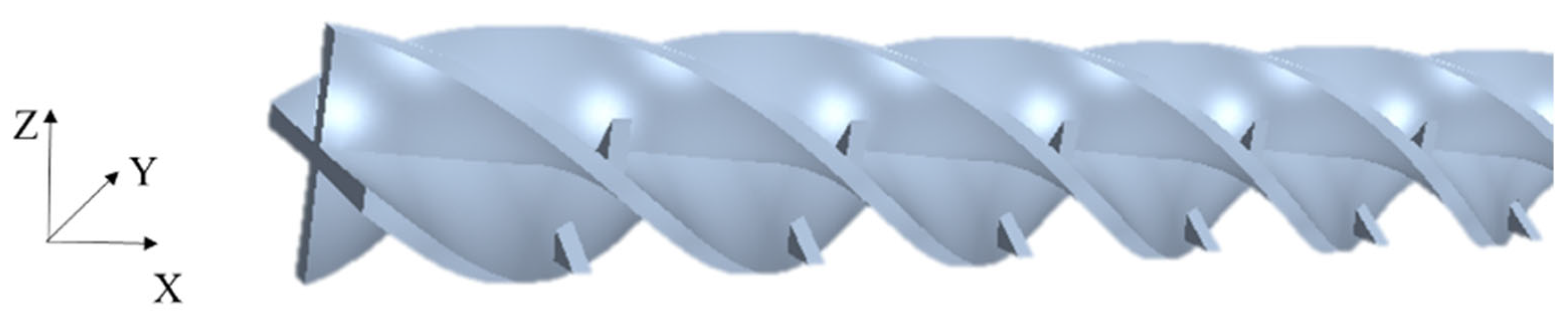
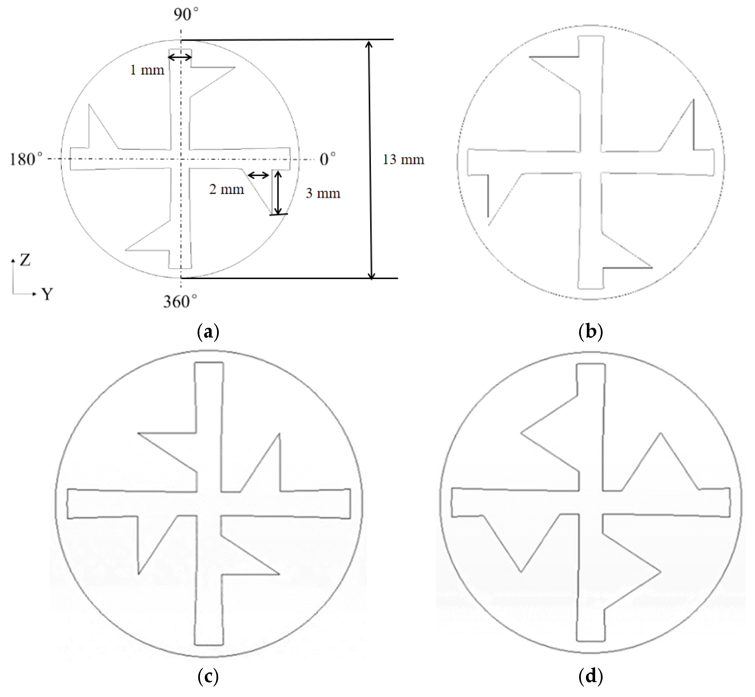
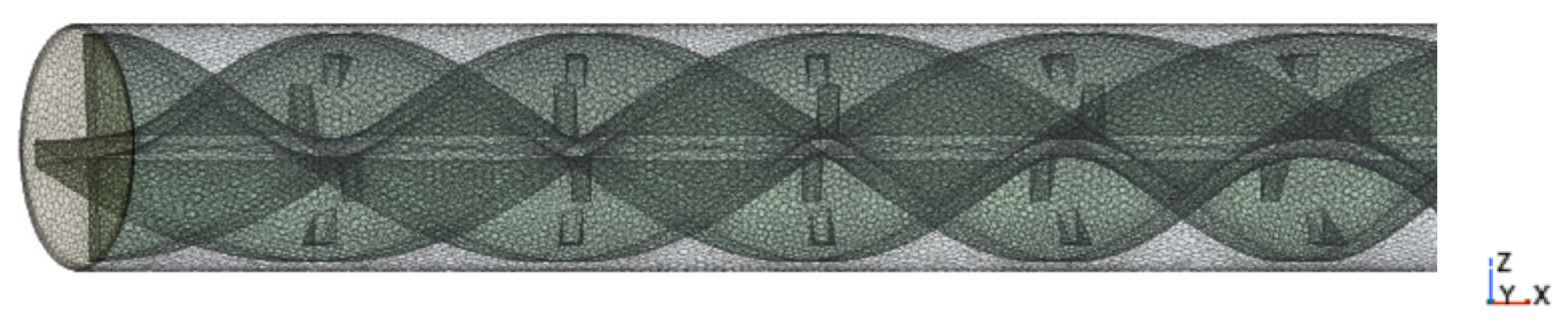
2.1. Physical Models

Based on the enhanced heat transfer technology, a novel insert, namely the CV, which combines a CCDTT and vortex generator, is proposed to achieve greater heat transfer enhancement. Subsequent simulations involve inserting CVs into a plain tube with a diameter (D) of 13 mm and length (L) of 500 mm. The CVs, made from high-thermal-conductivity aluminum and with a thickness of just 1 mm, are used in simulations where high-viscosity oil is the working fluid.
This paper presents four distinct CV designs, designated CVCP, CVAP, CVAC, and CVAD, which mainly differ in the shape and location of the vortex generator while maintaining a consistent CCDTT structure. As an example, the 3D model of CVCP is depicted in Figure 1, and the four different cross-sections of the CVs are shown in Figure 2. Additionally, the effects of twist ratios and angles are investigated once the CV geometry is determined. The twist ratio (y) is defined as the ratio of the length after a 180° reverse to the diameter, while the angle (α) represents the inclination of the vortex generator relative to the lubricating oil flow direction. The study considers twist ratios of 2.0, 3.0, 4.0, and ∞, and angles of 0°, 30°, and 60°.

2.2. Mathematical Equations

Before simulating the heat transfer and flow characteristics of enhanced heat exchanger tubes, several assumptions are made to simplify and focus the analysis. Firstly, the fluid flow is assumed to be laminar and incompressible, which is reasonable given the low flow velocities and high viscosity of the oil. The simulation focuses on steady-state conditions, neglecting any transient effects. Additionally, the influences of natural convection and thermal radiation are considered negligible compared to the forced convection and conduction processes dominant in this system. The thermophysical properties of the fluid, such as viscosity, thermal conductivity, and specific heat, vary with temperature and are modeled using polynomial expressions. Based on these assumptions, the forms of the three fundamental conservation equations (mass, momentum, and energy) are established as follows.
Equation of mass conservation:
u = 0
Equation of momentum conservation:
ρ ( u ) u = P + μ 2 u
where ρ is fluid density and μ is fluid dynamic viscosity.
Equation of energy conservation:
ρ C p ( u T ) = λ 2 T
where λ is fluid thermal conductivity and Cp is fluid specific heat.
The heat conduction equation in CVs is given below:
λ s 2 T = 0
where λs is solid thermal conductivity.

2.3. Data Reduction

Some of the physical quantities, such as Re, Nu, and so on, are defined in Equations (5)–(9).
Re = ρ u c D μ
Re s = ρ u c D s μ = Re π π 4 δ / D
Res [24] is a Reynolds number which takes the helical velocity produced by CVs into account.
h = ρ π 4 D s u c C p ( T i n T o u t ) π L T i n + T o u t 2 T w
N u = h D s λ
f = Δ P ( ρ u c 2 / 2 ) ( L / D s )
The performance evaluation criteria (PEC) [25] are defined as Equation (10).
P E C = N u / N u 0 ( f / f 0 ) 1 / 3

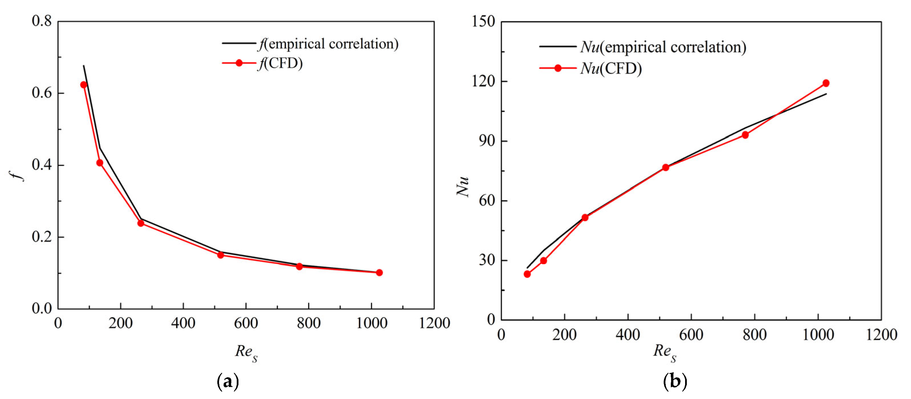
2.4. Numerical Validation

The hydrodynamics and heat transfer of tubes with CVs inserted are simulated by CFD software (https://www.ansys.com/products/fluids, accessed on 20 February 2025). A polyhedral mesh is used for the mainstream region, and a prism layer mesh with refinement near the wall is employed. The mesh for the CVCP part is shown in Figure 3. By checking the mesh quality, it is found that the volume change ratio is between 0.01 and 1, the face validity is 1, and the cell quality is between 0.08 and 1. The mesh quality is considered good, ensuring the convergence and accuracy of the calculations. To ensure the accuracy of the numerical simulations, mesh independence verification is necessary to confirm that the number of cells does not significantly affect the CFD simulation results. We conduct a mesh evaluation on the CVCP of y = 2, α = 0° and Re = 40. The outlet temperature (To) and the pressure drop (ΔP) are selected as monitoring quantities. As the number of cells increases from 1,396,841 to 5,049,568, the changes in the monitoring quantities To and ΔP with the number of cells are compared and presented in Table 2. The table shows that as the number of cells increases, the trends of the monitoring quantities become stable. Comparing mesh model #3 with #4, the change in ΔP is 0.008%, and the change in To is 0.035%, indicating that the number of cells at 3,312,913 is sufficient for mesh independence. Mesh model #3 can be selected for numerical simulations under vertical conditions.
The calculated Nusselt number and friction factor by simulations are compared with those of S. K. Agarwal and M. R. Rao [8] under the same high-viscosity liquid to verify the reliability of the simulation models at fully developed flow, which is presented in Figure 4. The results show that deviations between the calculated friction factor and Nusselt number are within ±8% and ±15%, respectively. The reasonable accuracy of the present numerical predictions is proven to a certain extent.

3. Analysis of Geometrical Models
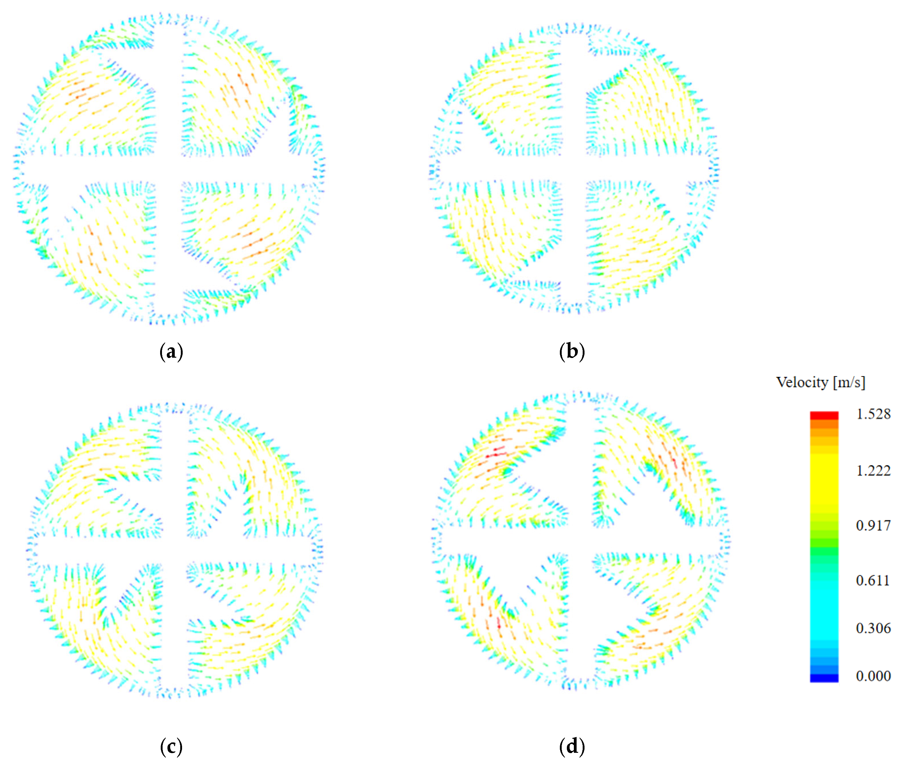
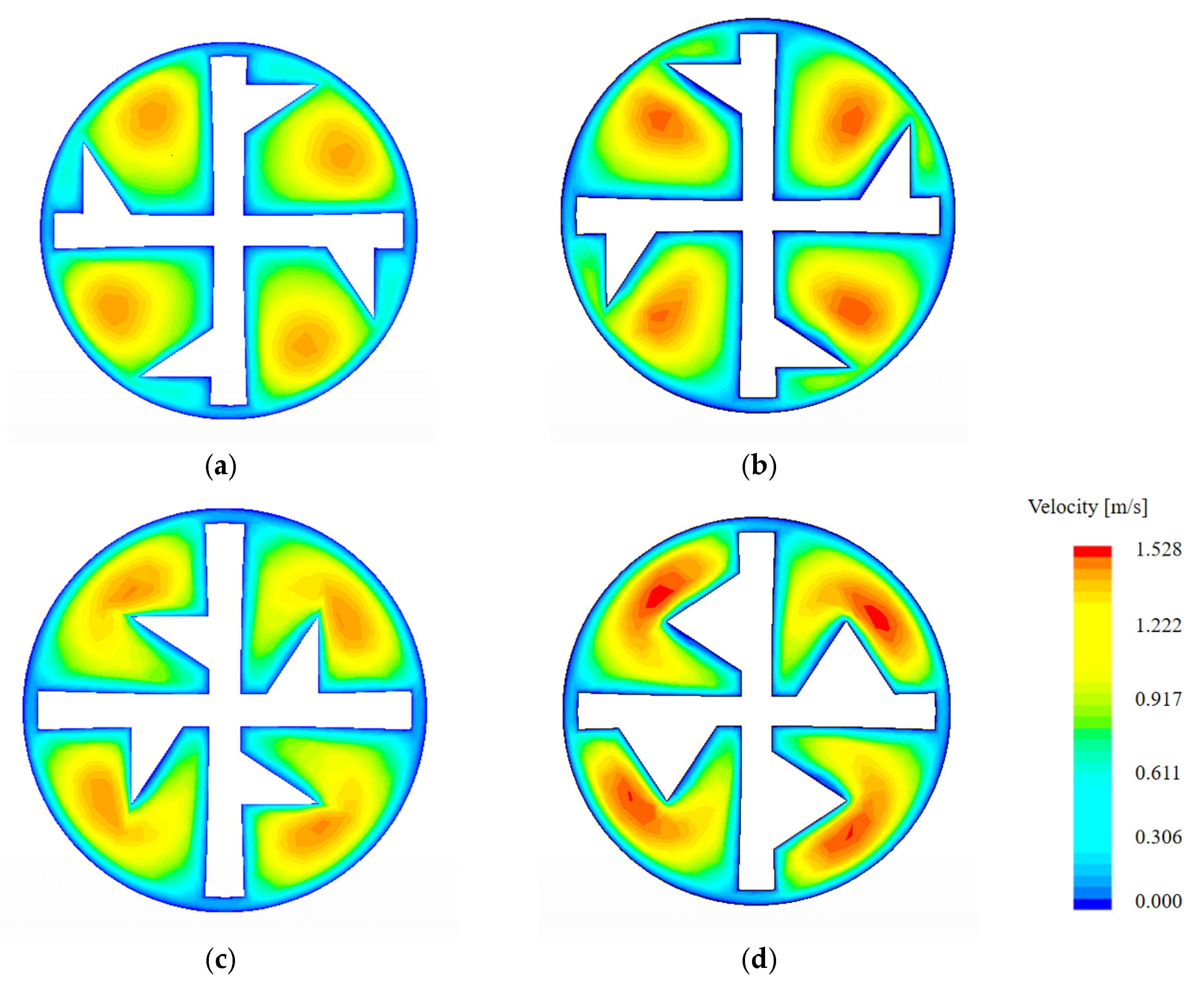
3.1. Velocity Field

In this section, the twist ratios (y) and angles (α) were maintained at 2.0 and 0°, respectively, while modifying the geometric configurations of the vortex generators (CVs). Figure 5 displays the velocity vector diagrams at the L = 0.312 m cross-section of tubes equipped with different CVs under Reynolds number 202. For a clearer comparison, Figure 6 presents velocity nephograms of various CVs at the same axial position (L = 0.312 m) and Reynolds number. The lubricating oil flow demonstrates four distinct velocity partitions with rotational symmetry characteristics. Analysis reveals that under constant-flow-rate conditions, the cross-sectional velocity increases with decreasing flow area. When the lubricating oil rotates with the twisted tape, the velocity field exhibits significant enhancement, with the maximum velocity location shifting from the central region to the vicinity of the vortex generator. The peak velocities for CVCP, CVAP, CVAC, and CVAD configurations measure 1.36 m/s, 1.39 m/s, 1.481 m/s, and 1.527 m/s, respectively. Minimum velocities (0 m/s) consistently occur at the wall surfaces. Comparative analysis indicates that CVAD increases the solid-occupied flow area by 9.1% compared to CVCP, CVAP, and CVAC configurations. Notably, CVAD achieves 12.28% higher maximum velocity than CVCP. The velocity distribution at different positions characterizes the corresponding pressure distribution, while the fluid flow patterns directly influence heat transfer mechanisms, thereby affecting the thermal field distribution.

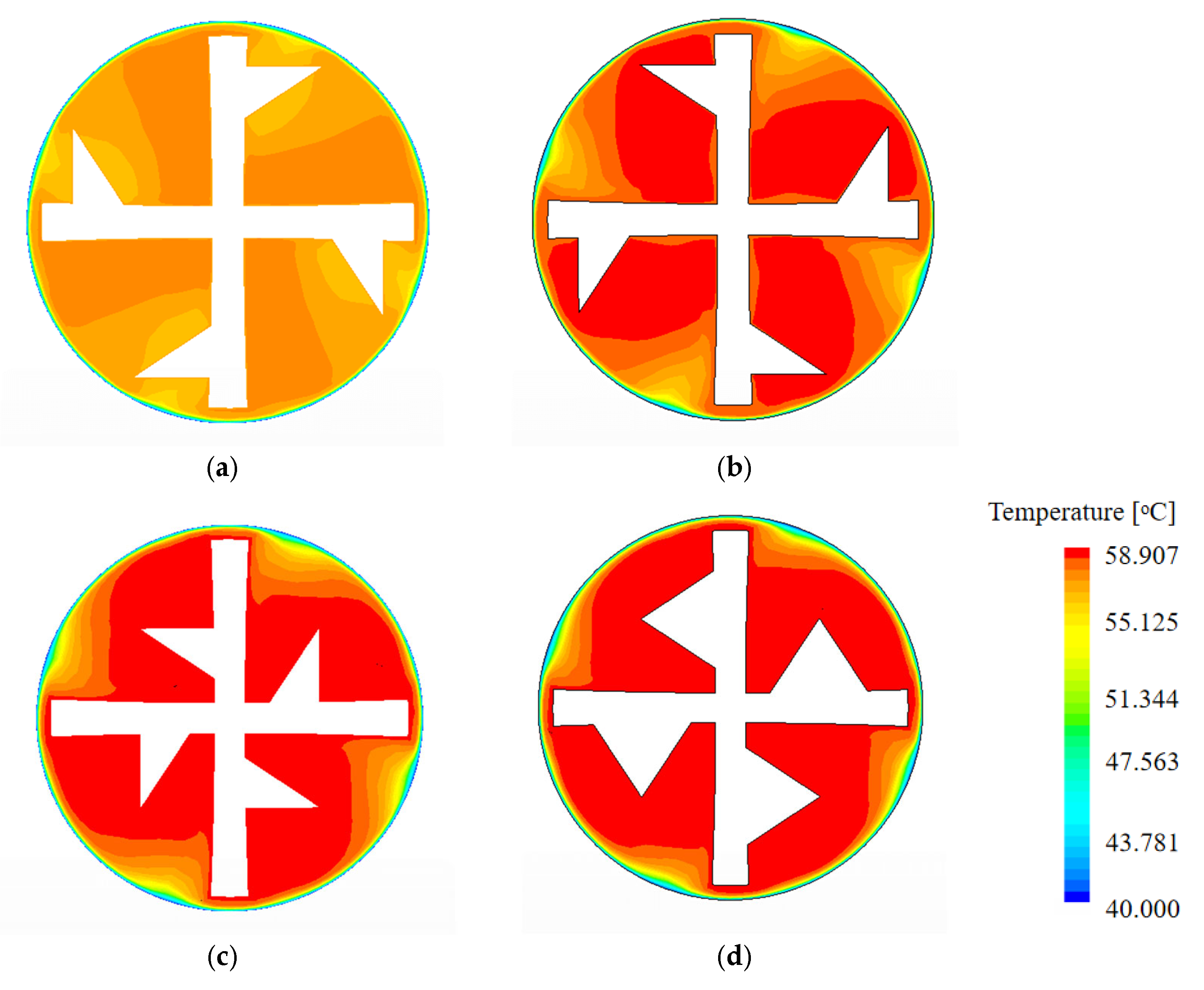
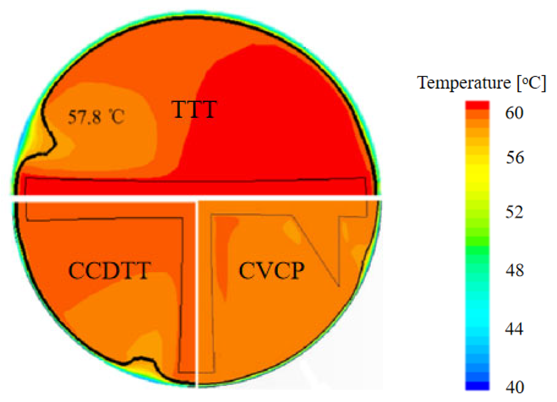
3.2. Temperature Field

Figure 7 presents the temperature fields for enhanced tubes with CVs at L = 0.312 m and Re = 202. The temperature distribution exhibits rotational symmetry, resulting from the symmetrical velocity field induced by the CVs. The average oil temperature within the tube decreases as the vortex generator is positioned closer to the tube wall. This is attributed to the increased oil velocity near the wall, which enhances the temperature gradient and heat transfer rate. Notably, the tube equipped with CVCP maintains the lowest average oil temperature, indicating its superior heat transfer performance among the four CV configurations.

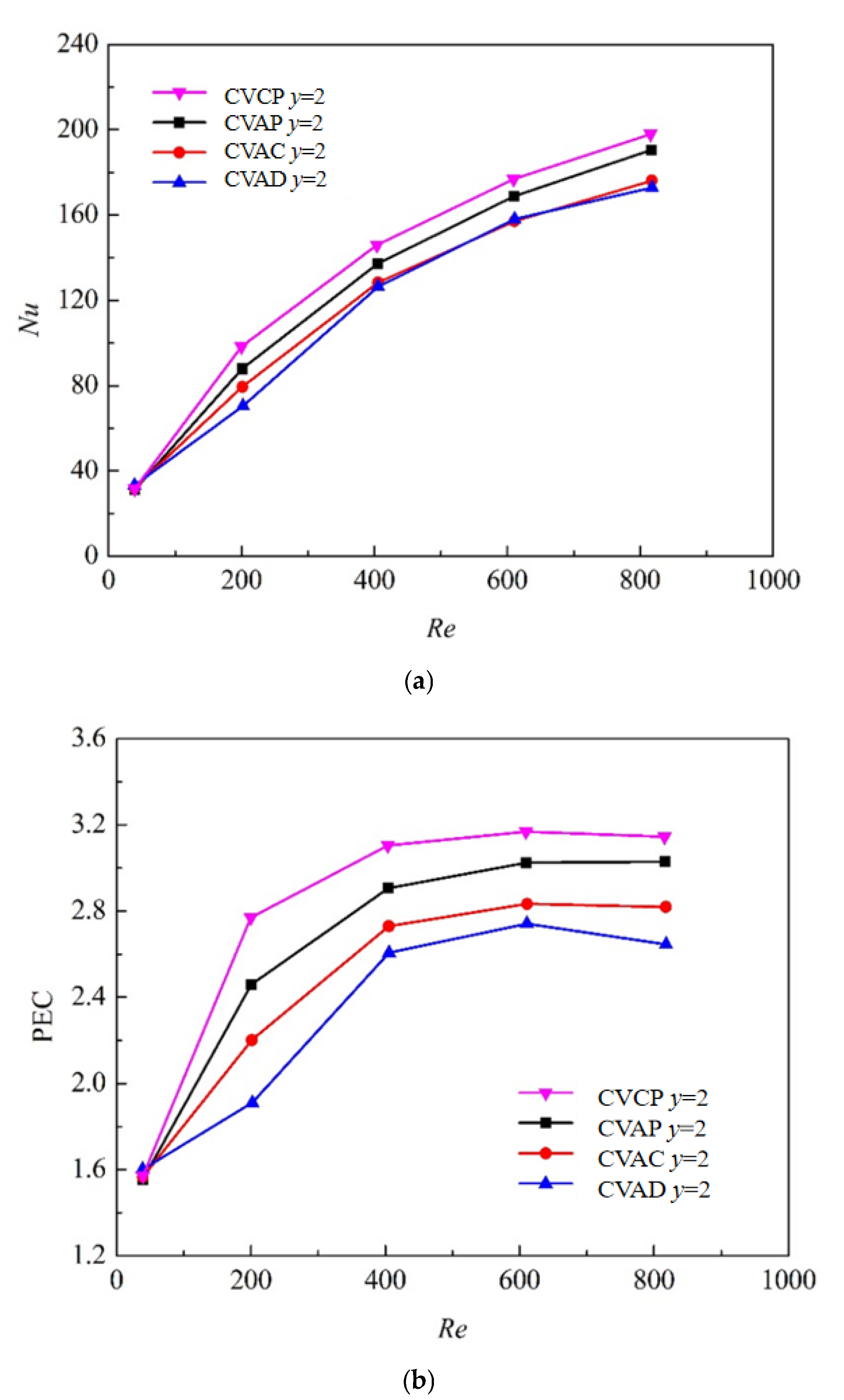
3.3. Convective Heat Transfer Characteristics

The relationships between Nusselt number, performance evaluation criterion, and Reynolds number for tubes equipped with different vortex generators (CVs) are presented in Figure 8. The results demonstrate significant geometric dependence of heat transfer enhancement. As anticipated, the Nusselt number exhibits a monotonic increase with Reynolds number, while the PEC values initially rise before stabilizing or even declining at higher Re. This phenomenon arises because escalating Reynolds numbers amplify flow resistance more rapidly than heat transfer enhancement, ultimately causing the PEC’s growth rate to plateau or diminish. Among the four configurations, the CVCP-equipped tube achieves optimal performance with maximum Nu and PEC values of 198 and 3.17, respectively. In contrast, the CVAD configuration yields substantially lower peak values (Nu = 162, PEC = 2.63). The performance variations stem from fundamental geometric differences: (1) The counterclockwise vortex orientation in CVAP aligns with lubricant flow direction, reducing central flow disturbance. (2) CVAC’s vortex generators being positioned closer to the central axis weakens the thermal boundary layer disruption. (3) CVAD’s increased solid occupation proportion compromises flow dynamics. These comparative analyses confirm that CVCP’s geometric configuration provides superior thermal–hydraulic synergy through optimized vortex-induced turbulence near the wall region.

4. Analysis of Influencing Factors

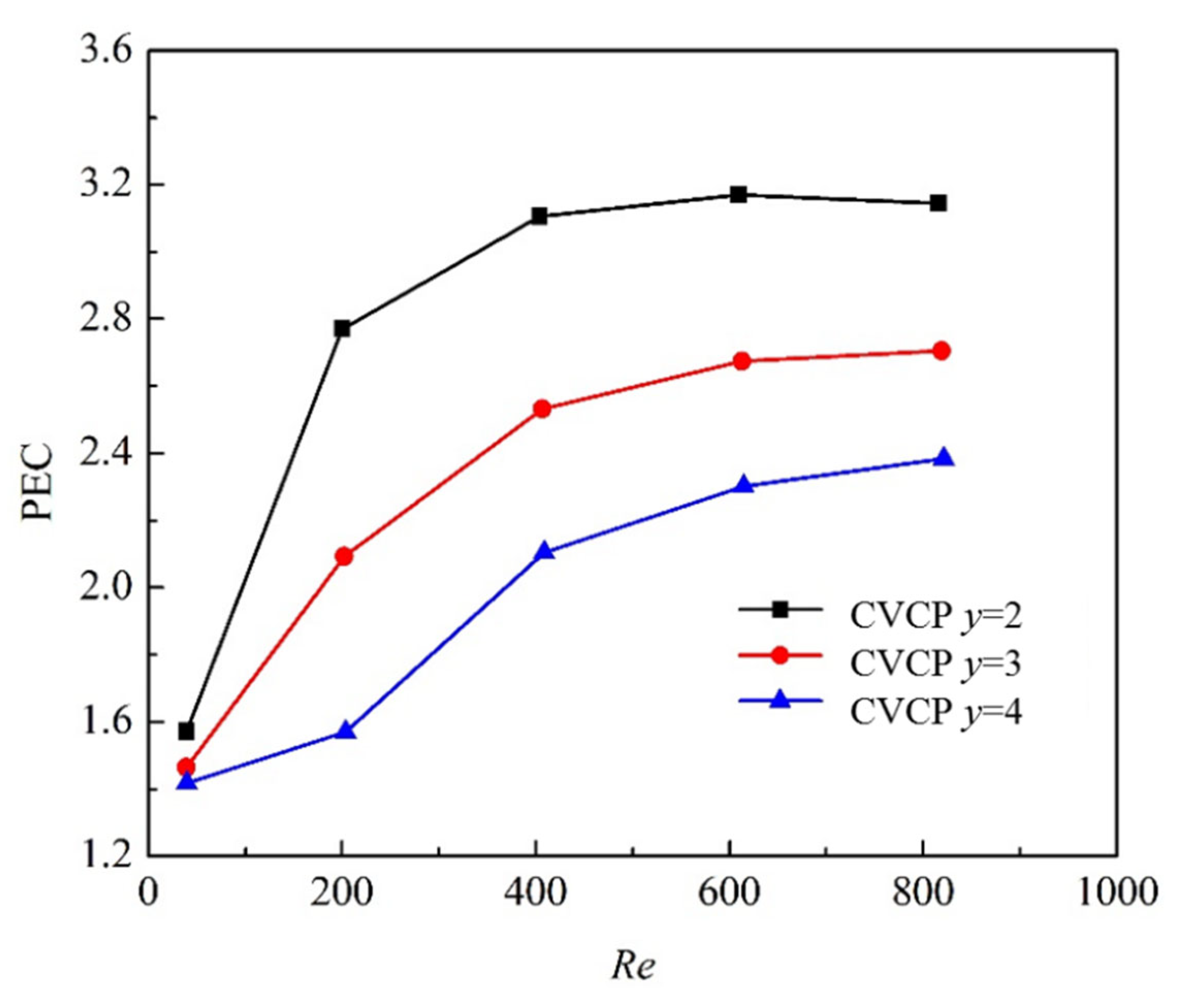
4.1. Effect of Twist Ratio

The CVCP configuration exhibits the highest heat transfer enhancement among the four geometric configurations. This section delves into the heat transfer performance of CVCP, focusing on the critical factors of twist ratio (y) and angle (α). We first examine the effect of the twist ratio. Figure 9 illustrates the friction factors (f) and Nusselt numbers (Nu) for CVCPs with different twist ratios. The results indicate that the Nu for oil in tubes fitted with CVCP increases as the twist ratio decreases within the Reynolds number range of 40 to 830. However, a decrease in twist ratio also leads to an increase in the drag coefficient of the enhanced tube. For instance, when y = 2.0, the heat transfer enhancement is maximized, with the Nu reaching up to 198 in tubes fitted with CVCP. The corresponding heat transfer coefficient is 1928 W/(m2·K). Quantitatively, the Nu for oil in tubes fitted with CVCP at a twist ratio of 2.0 is 146% to 470% higher than that in bare tubes. However, the drag coefficient for this configuration is 14.7 to 35 times that of bare tubes. In summary, while lower twist ratios enhance heat transfer performance, they also significantly increase the drag coefficient, which needs to be carefully considered in practical applications.
Figure 10 depicts the variation curves of the performance evaluation criterion (PEC) for tubes inserted with CVCP across various twist ratios and Reynolds numbers. The PEC of the enhanced tube rises as the twist ratio decreases at the same Reynolds number. When the twist ratio is held constant, the PEC of the CVCP-inserted tube displays an upward trend with increasing Reynolds number. For instance, at a twist ratio of 4.0, the PEC of lubricating oil climbs from 1.42 to 2.38 as the Reynolds number increases from 40 to 820, reaching a maximum PEC of 2.38 at Re = 820. A similar pattern is observed when the twist ratio is 3.0. However, for y = 2.0, as the Reynolds number ranges from 609 to 816, the PEC of lubricating oil slightly drops from 3.17 to 3.15, a decrease of 0.02. Conversely, when the Reynolds number increases from 40 to 609, the PEC continues to rise. The explanation lies in the fact that when y ≥ 3.0, velocity is the dominant factor influencing PEC variation. In contrast, when y ≤ 2.0, the spiraling motion induced by the CVCP in the lubricating oil results in a higher PEC at lower velocities. As the velocity increases, the growth rate of flow resistance surpasses that of heat transfer performance, leading to a reduction in the PEC of the CVCP-inserted tube. The highest PEC value for the CVCP-fitted tube is 3.17 at y = 2.0.

4.2. Effect of Angle

Previous findings have demonstrated that for tubes fitted with CVCP, the twist ratio significantly impacts the oil-side heat transfer performance. We now turn our attention to the influence of the angle on the heat transfer coefficient. Specifically, we investigate three distinct angles (α = 0°, 30°, and 60°) formed between the coaxial cross-twin twisted tape and vortex generator. Here, α = 0° signifies that the vortex generator is aligned with the positive z-axis without any inclination.
Figure 11 illustrates the relationship between the Nusselt number (Nu), the friction factor, and the Reynolds number for enhanced tubes fitted with CVCP at y = 2.0 and different angles. As shown, the heat transfer enhancement effect of the CVCP-inserted tube decreases with increasing angle, although this decline in the rate of increase slows down or even halts when the angle reaches 30°. For example, when α = 60°, the Nu of the lubricating oil is 3.52 to 6.44 times that of a plain tube. In comparison, at α = 30°, the Nu is 2.49 to 5.67 times that of a plain tube, and at α = 0°, it is 2.46 to 5.69 times that of a plain tube, which is very close to the 30° scenario. Regarding the friction factor for tubes fitted with CVCP at different angles, it slightly diminishes as the angle increases, but the reduction is minimal. Overall, the inclination angle has a negligible impact on the friction factor. In summary, while the angle affects the heat transfer performance of CVCP-enhanced tubes, the specific impact varies with the angle’s magnitude, and the friction factor remains largely unaffected by angular changes.
Within the angle range of 0° to 60°, the friction factors of tubes inserted with CVCPs are roughly the same, but for Nusselt numbers, α = 0° yields the best heat transfer enhancement. The relationships between the performance evaluation criterion (PEC) of tubes fitted with CVCPs at different angles and the Reynolds number (Re) are shown in Figure 12. The research results indicate that at a constant Re, the PEC of the tube with CVCPs decreases as the angle increases. The maximum PEC for α = 0° is 3.17, while for 60° it is 3.05. Moreover, the PEC of the enhanced tube initially rises and then levels off with an increase in Re when the angles are fixed, with the PEC turning point at Re = 610.

5. Compared with CCDTT and TTT

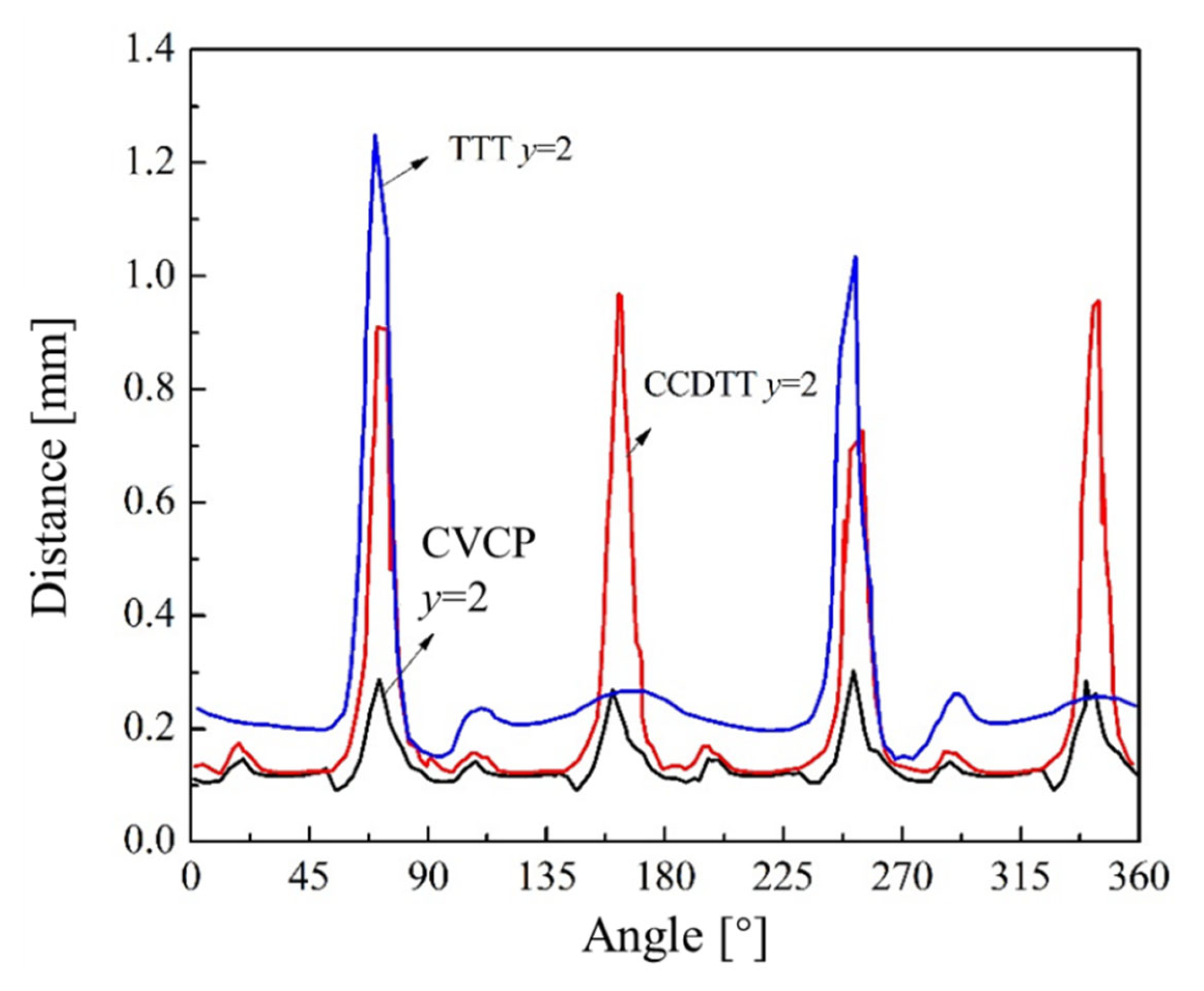
5.1. Local Flow Field
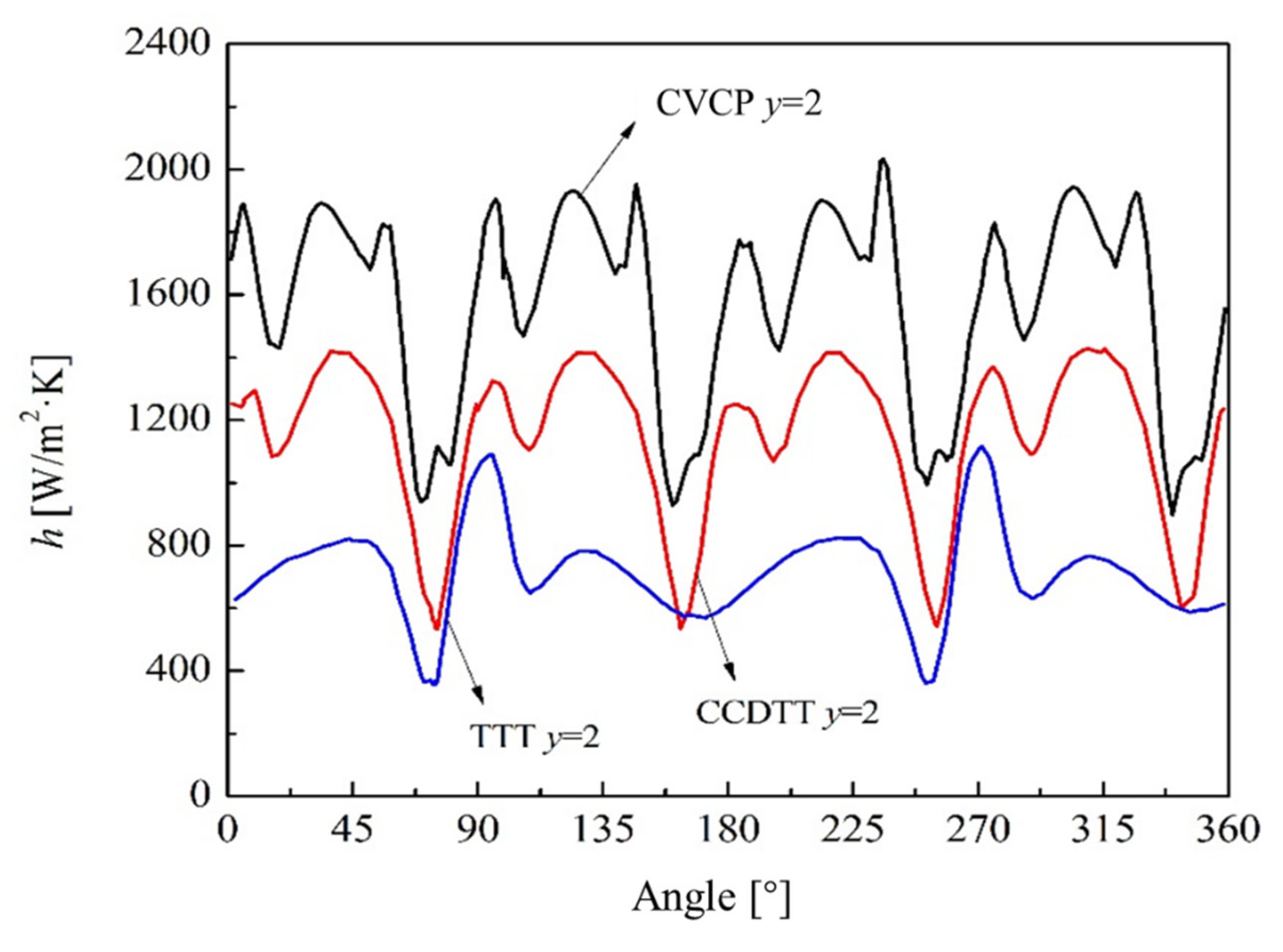
Studies indicate that the CVCP with y = 2.0 and α = 0° achieves the highest heat transfer enhancement. Therefore, we selected CVCPs for comparison with CCDTTs and traditional TTTs. Figure 13 displays the isothermal lines of 57.8 °C in the cross-sectional temperature field, taken 312 mm from the inlet at Re = 412 and y = 2.0. The results show that the lubricating oil temperature in the CVCP-equipped tube is lower than that in the TTT and CCDTT tubes, with a more uniform temperature distribution. For example, the average cross-sectional temperatures are 58.61 °C for the CVCP-inserted tube, 59.53 °C for the TTT, and 58.85 °C for the CCDTT.
Compared to TTTs and CCDTTs, the CVCP-equipped tube has a more uniform temperature distribution, resulting in a steeper temperature gradient and a thinner thermal boundary layer. To quantify the thermal boundary layer changes, Figure 14 shows the distance from the 57.8 °C isothermal line to the wall as a function of the circular angle. At a twist ratio of 2.0, the distance trend for the CVCP-inserted tube is more moderate than that for the CCDTT and TTT. However, the maximum height of the CVCP is the smallest. Specifically, the average distance between the isotherm and the wall is 0.2 mm for the TTT-inserted tube, 0.12 mm for the CCDTT, and just 0.1 mm for the CVCP.

5.2. Heat Transfer

A thinner thermal boundary layer means a steeper temperature gradient, indicating enhanced heat transfer. Figure 15 shows the circumferential heat transfer coefficient for tubes fitted with TTT, CCDTT, and CVCP. Previous analyses of CCDTT and TTT are referenced, with this paper focusing on CVCP. Overall, CVCP offers the best heat transfer enhancement. The distance from the isotherm to the wall varies with the local convective heat transfer coefficient and the circumference angle. When the circumference angle is between 0° and 5°, the gap between CVCP and the tube wall is only 0.5 mm, and the heat transfer coefficient rises to 1800 W/(m2·K). As the circumference angle increases from 5° to 18°, the heat transfer coefficient drops noticeably, and the distance from the isotherm to the wall peaks due to lower velocity.
As the circumference angle increases, the convective heat transfer is enhanced because the velocity reaches its maximum, causing the heat transfer characteristic to peak at 1900 W/(m2·K) between 18° and 33°. At 51° to 57°, there is a slight increase in the heat transfer coefficient, but beyond 57°, it rapidly decreases to a minimum of 940 W/(m2·K) at 70°, where the distance between the isotherm and the wall also reaches its maximum of 0.3 mm. Due to the gap between the CVCP and the wall, the heat transfer coefficient rises again, and this pattern repeats every 90°, with the distance between the isotherm and the wall also following this cycle. Studies on the local circumferential heat transfer coefficients of plain tubes fitted with CCDTT, TTT, and CVCP show that CVCP has the greatest effect. Further research on the overall enhanced heat transfer effects of tubes with the new compound CVCP is necessary.
Figure 16 illustrates how the average Nusselt number and PEC of tubes inserted with TTT, CCDTT, and CVCP vary with the Reynolds number at a twist ratio of 2.0. Figure 16a reveals that as the inlet velocity increases, the heat transfer enhancement effects of tubes with TTT, CCDTT, and CVCP for lubricating oil improve. When the twist ratio is constant, the Nu of CVCP-inserted tubes is higher than that of CCDTT and TTT tubes across the entire Reynolds number range of 40 to 830, indicating that CVCP offers the best heat transfer performance among the three inserts. Compared to TTT and CCDTT, the average Nusselt numbers of lubricating oil in CVCP-inserted tubes are 2.52 to 5.44 times and 1.35 to 1.86 times higher than those of CCDTT and TTT tubes, respectively. Figure 16b shows the relationship between Reynolds number and PEC for CVCP, CCDTT, and TTT tubes. The PEC of CVCP-fitted tubes is the highest among the three inserts, reaching 3.20 within the Reynolds number range of 40 to 830. Quantitatively, the PEC of CVCP-fitted tubes is 0.99 to 1.15 times that of CCDTT tubes and 1.14 to 1.54 times that of TTT tubes, demonstrating CVCP’s superior enhancement effect compared to TTT.

6. Conclusions

In this study, we explored the heat transfer enhancement of highly viscous lubricating oil using a CV (coaxial cross double-twisted tape and vortex generator) structure. Our simulations revealed that among the tested configurations, the CVCP structure achieved the highest heat transfer enhancement. Further analysis showed that the CVCP’s superior performance was due to longitudinal vortices that increased wall-proximity velocity and thinned the thermal boundary layer. Compared to plain tubes, the CVCP tubes had Nusselt numbers 160% to 470% higher and 1% to 15% higher than CCDTTs when y = 2 and α = 0°. The PEC of CVCP was larger than CCDTTs and TTTs across the tested Reynolds number range, reaching a maximum of 3.20. From an industrial perspective, the CVCP structure holds significant promise for improving heat exchange efficiency in high-viscosity lubricating oil cooling systems, potentially reducing equipment size and energy consumption.

Author Contributions

X.L. and X.Z. proposed the research point and performed numerical simulation and manuscript writing. L.R., M.L. and Y.Z. (Yinxing Zhang) participated in the data analysis process. Y.Z. (Yongfa Zhang) and S.L. supervised this study. H.X. and M.D. provided critical feedback and revised the manuscript. All the authors contributed to the paper’s supervision and revision. All authors have read and agreed to the published version of the manuscript.

Funding

This research was funded by Key Basic Research Projects of the Foundation Strengthening Plan, grant number 2023-JCJQ-ZD-131-00.

Data Availability Statement

The original contributions presented in this study are included in the article. Further inquiries can be directed to the corresponding author.

Conflicts of Interest

The authors declare no conflicts of interest.

Nomenclature

Cpspecific heat capacity, kJ/(kg·K)δthickness, m
Ddiameter of the tube, mmΛheat conductivity, W/(m·K)
ffriction factorυkinetic viscosity, Pa·s
hconvective heat transfer coefficient, W/(m2·K)μdynamic viscosity, m2/s
Ltest section length, mρdensity, kg/m3
NuNusselt number
ΔPpressure drop, PaSubscripts
PECperformance evaluation criterioncfor the average
PrPrandtl numberffor the fluid
ReReynolds numberinfor the inlet
ResReynolds number based on swirl velocitysfor the solid
Ttemperature, oCofor the oil
uvelocity, m/soutfor the outlet
ytwist ratiox, y, zcoordinates
wfor the wall
Greek letters0for the plain tube
αangle, °

References

  1. Bergles, A.E. Handbook of Heat Transfer Applications; McGraw-Hill: New York, NY, USA, 1985; Volume 13. [Google Scholar]
  2. Bergles, A.E. Heat transfer enhancement the encouragement and accommodation of high heat fluxes. ASME J. Heat Transf. 1997, 119, 8–19. [Google Scholar]
  3. Bergles, A.E. Exhft for fourth generation heat transfer technology. Exp. Therm. Fluid Sci. 2002, 26, 335–344. [Google Scholar]
  4. Hsieh, S.S.; Huang, I.W. Heat transfer and pressure drop of laminar flow in horizontal tubes with/without longitudinal inserts. J. Heat Transf. (ASME) 2000, 122, 465–475. [Google Scholar]
  5. Manglik, R.M.; Bergles, A.E. Heat transfer and pressure drop correlations for twisted tape inserts in isothermal tubes: Part I-laminar flows. Trans. ASME J. Heat Transf. 1993, 115, 881–889. [Google Scholar]
  6. Manglik, R.M.; Bergles, A.E. Heat transfer and pressure drop correlations for twisted-tape inserts in isothermal tubes, part II: Transition and turbulent flows. Trans. ASME J. Heat Transf. 1993, 115, 890–896. [Google Scholar]
  7. Kumar, C.N.; Murugesan, P. Review on twisted tapes heat transfer enhancement. Int. J. Sci. Eng. Res. 2012, 3, 1–9. [Google Scholar]
  8. Saha, S.K.; Dutta, A.; Dhal, S.K. Friction and heat transfer characteristic of laminar swirl through a circular tube fitted with regularly spaced twisted-tape elements. Int. J. Heat Mass. Transf. 2001, 44, 4211–4223. [Google Scholar]
  9. Pal, P.K.; Saha, S.K. Experimental investigation of laminar flow of viscous oil through a circular tube having integral spiral corrugation roughness and fitted with twisted tapes with oblique teeth. Exp. Therm. Fluid. Sci. 2014, 57, 301–309. [Google Scholar]
  10. Liu, X.; Li, C.; Cao, X.; Yan, C.; Ding, M. Numerical analysis on enhanced performance of new coaxial cross twisted tapes for laminar convective heat transfer. Int. J. Heat Mass Transf. 2018, 121, 1125–1136. [Google Scholar]
  11. Zhou, G.; Feng, Z. Experimental investigations of heat transfer enhancement by plane and curved winglet type vortex generators with punched holes. Int. J. Therm. Sci. 2014, 78, 26–35. [Google Scholar]
  12. Modi, A.J.; Rathod, M.K. Comparative study of heat transfer enhancement and pressure drop for fin-and-circular tube compact heat exchangers with sinusoidal wavy and elliptical curved rectangular winglet vortex generator. Int. J. Heat Mass. Tran. 2019, 141, 310–326. [Google Scholar]
  13. Song, K.; Tagawa, T.; Chen, Z.; Zhang, Q. Heat transfer characteristics of concave and convex curved vortex generators in the channel of plate heat exchanger under laminar flow. Int. J. Therm. Sci. 2019, 137, 215–228. [Google Scholar]
  14. Naphon, P. Heat transfer and pressure drop in the horizontal double pipes with and without twisted tape insert. Int. Commun. Heat Mass Transf. 2006, 33, 166–175. [Google Scholar]
  15. Luo, C.; Wu, S.; Song, K.; Hua, L.; Wang, L. Thermo-hydraulic performance optimization of wavy fin heat exchanger by combining delta winglet vortex generators. Appl. Therm. Eng. 2019, 163, 114343. [Google Scholar]
  16. Rout, P.K.; Saha, S.K. Laminar flow heat transfer and pressure drop in a circular tube having wire-coil and helical screw-tape inserts. J. Heat Transf. (ASME) 2013, 135, 021901. [Google Scholar]
  17. Al-Fahed, S.; Chamra, L.; Chakroun, W. Pressure drop and heat transfer comparison for both micro fin tube and twisted tape inserts in laminar flow. Exp. Therm. Fluid. Sci. 1999, 18, 323–333. [Google Scholar]
  18. Sivashanmugam, P.; Suresh, S. Experimental studies on heat transfer and friction factor characteristics of laminar flow through a circular tube fitted with helical screw tape inserts. Appl. Therm. Eng. 2006, 26, 1990–1997. [Google Scholar]
  19. Khoshvaght-Aliabadi, M.; Davoudi, S.; Dibaei, M. Performance of agitated-vessel U tube heat exchanger using spiky twisted tapes and water based metallic nanofluids. Chem. Eng. Res. Des. 2018, 133, 26–39. [Google Scholar]
  20. Khoshvaght-Aliabadi, M.; Ghodrati, P.; Khaligh, S.F.; Kang, Y.T. Improving supercritical CO2 cooling using conical tubes equipped with non-uniform twisted inserts. Int. Commun. Heat Mass Transf. 2024, 150, 107171. [Google Scholar]
  21. Alkhamis, N. Heat transfer enhancement for fluid flow inside a channel by using metal foam. Int. Commun. Heat Mass Transf. 2025, 162, 108574. [Google Scholar]
  22. Jeon, Y.H.; Hong, J.H.; Kang, H.C. An empirical correlation for enhanced heat transfer in spirally fluted tube crossflow convection. Results Eng. 2025, 25, 103596. [Google Scholar]
  23. Hong, Y.; Kang, Z.; Fan, J. Heat transfer enhancement of pulsating heat pipes with novel structures. Appl. Therm. Eng. 2025, 268, 125720. [Google Scholar]
  24. Murugesan, P.; Mayilsamy, K.; Suresh, S. Heat transfer and friction factor studies in a circular tube fitted with twisted tapes consisting of wire nails. Chin. J. Chem. Eng. 2010, 18, 1038–1042. [Google Scholar]
  25. Webb, R.L.; Kim, N.H. Principles of Enhanced Heat Transfer; Taylor & Francis Group: New York, NY, USA, 2005. [Google Scholar]
Figure 1. Three-dimensional geometries of CVCP.
Processes 13 00938 g001
Figure 2. Cross-section of CVs: (a) CVCP; (b) CVAP; (c) CVAC; (d) CVAD.
Processes 13 00938 g002
Figure 3. Mesh grid cut planes of CVCP.
Processes 13 00938 g003
Figure 4. The comparison between the calculated results and empirical correlation: (a) f; (b) Nu.
Processes 13 00938 g004
Figure 5. The velocity vector of tubes fitted with CVs at L = 0.312 m and Re = 202: (a) CVCP; (b) CVAP; (c) CVAC; (d) CVAD.
Processes 13 00938 g005
Figure 6. The velocity nephograms of tubes fitted with CVs at L = 0.312 m and Re = 202: (a) CVCP; (b) CVAP; (c) CVAC; (d) CVAD.
Processes 13 00938 g006
Figure 7. Temperature fields of tubes fitted with CVs at L = 0.312 m and Re = 202: (a) CVCP; (b) CVAP; (c) CVAC; (d) CVAD.
Processes 13 00938 g007
Figure 8. Nusselt number and PEC curves of tubes with inserted CVs in relation to Reynolds number (y = 2, α = 0°): (a) Nu; (b) PEC.
Processes 13 00938 g008
Figure 9. Nu and f curves of tubes with inserted CVCP with different y as a function of Reynolds number (α = 0°): (a) Nu; (b) f.
Processes 13 00938 g009
Figure 10. PEC curves of tubes with inserted CVCP with different y as a function of Reynolds number (α = 0°).
Processes 13 00938 g010
Figure 11. Nu and f curves of tubes with inserted CVCP with different α as a function of Reynolds number (y = 2): (a) Nu; (b) f.
Processes 13 00938 g011
Figure 12. PEC curves of tubes with inserted CVCP with different α as a function of Reynolds number (y = 2).
Processes 13 00938 g012
Figure 13. Temperature fields for tubes inserted with TTT and CCDTT and CVCP.
Processes 13 00938 g013
Figure 14. Distances curves of tubes inserted with TTT, CCDTT and CVCP as a function of angle.
Processes 13 00938 g014
Figure 15. Circumferential local convective heat transfer coefficients in tubes inserted with TTT, CCDTT and CVCP (Re = 412, L = 0.312).
Processes 13 00938 g015
Figure 16. Nusselt number and PEC curves of tubes inserted with TTT, CCDTT and CVCP (y = 2) as a function of Reynolds number. (a) Nusselt number; (b) PEC.
Processes 13 00938 g016
Table 1. Summary of passive heat transfer enhancement techniques.
Technology
Category
Representative
Study
MethodKey FindingsApplication
Scenarios
Ref.
Twisted Tapes
Conventional
Twisted Tapes (TTT)
Manglik & Bergles, KumarExperimental and TheoreticalUniversal correlations for Nu and f in laminar/turbulent flows; validated secondary flow effectsLow-viscosity fluids
(laminar/turbulent)
[5,6,7]
Periodically Spaced TapesSaha et al.Experimental (laminar) Periodic spacing enhances Nu by 1.8× and f by 2.1× (Re = 1000–5000)High-viscosity laminar flows[8]
Oblique-Teeth Twisted TapesPal & SahaExperimental (laminar) Oblique teeth improve fluid mixing; Nu increases 3.2× vs. Smooth tube (Re = 500–2000)High-viscosity oils[9]
Coaxial Cross Double-Twisted Tapes (CCDTT)Liu et al.Numerical (laminar)Dual-tape cross structure generates bidirectional vortices; Nu 35% higher than TTT; f increases only 18%High-viscosity fluids (lubricants)[10]
Vortex Generators
Flat Winglet VG with PerforationsZhou et al.Experimental (Laminar/Turbulent) Perforated winglets increase Nu by 25% but raise f by 40%Air/low-viscosity fluids[11]
Sinusoidal vs. Elliptical VGModi & RathodNumericalElliptical VG achieves 12% higher Nu and 8% lower pressure drop than sinusoidal VGCompact heat exchangers[12]
Concave/Convex Curved VGSong et al.Experimental (laminar) Convex VG yields 18% higher Nu than concave VG with comparable pressure dropPlate heat exchangers[13]
Compound Techniques
Twisted Tapes + Corrugated TubesNaphonExperimental (Double-Pipe Laminar)Nu enhanced 2.5×, but pressure drop increased 3.8× (Re = 800–3000)High-viscosity oils[14]
Twisted Tapes + VGLuo et al.Numerical45° VG attack angle achieves PEC = 1.28 (19% higher than single techniques)Compact finned heat exchangers[15]
Helical Screw Tapes + Wire CoilsRout & sahaExperimental (laminar)Combined inserts improve Nu by 40% vs. single inserts; f increases 2.3×High-viscosity fluids (e.g., polymer melts)[16]
Other Passive Techniques
Microfin TubesAl-Fahed & ChakrounExperimental (laminar)Microfin tubes increase Nu by 30% vs. smooth tubes; f increases 1.5× (Re = 500–1500)Low-viscosity laminar flows[17]
Helical Screw InsertsSivashanmugam et al.Experimental (laminar)Periodic shear-induced mixing improves Nu by 2.6×; f increases 6.4× (Re = 20–100)High-viscosity laminar flows
(e.g., polymer solutions)
[18]
Spiky Twisted TapesKhoshvaght-AliabadiExperimental (turbulent)Heat transfer coefficient is increased by 11–67%Water-based metal-lic nanofluids[19]
Conical Horizontal Tubes (CHTs)Khoshvaght-AliabadiNumericalThe heat transfer coefficient is increased by 43.1% and the pressure drop is reduced by 36.7%Supercritical CO2 [20]
Table 2. Grid independence verification.
ModelGrid NumberΔP [Pa]To [°C]
#11,396,84122,674.3255.68
#22,452,70222,823.4756.73
#33,312,91322,886.6556.87
#45,049,56822,888.5256.89
Disclaimer/Publisher’s Note: The statements, opinions and data contained in all publications are solely those of the individual author(s) and contributor(s) and not of MDPI and/or the editor(s). MDPI and/or the editor(s) disclaim responsibility for any injury to people or property resulting from any ideas, methods, instructions or products referred to in the content.

