Article

SCA Fracturing Mechanisms of Rock Mass and Application in Overhanging Roof Structure Fragmentation of Mine Goaf

1
School of Energy Science and Engineering, Henan Polytechnic University, Jiaozuo 454000, China
2
School of Civil Engineering and Communication, North China University of Water Resources and Electric Power, Zhengzhou 450045, China
3
Institute of Mechanics, Chinese Academy of Sciences, Beijing 100190, China
4
School of Engineering Science, University of Chinese Academy of Sciences (UCAS), Beijing 101408, China
*
Authors to whom correspondence should be addressed.
Processes 2025, 13(5), 1275; https://doi.org/10.3390/pr13051275
Submission received: 11 March 2025 / Revised: 14 April 2025 / Accepted: 21 April 2025 / Published: 22 April 2025
(This article belongs to the Section Energy Systems)

Abstract

:
During coal resource mining, hard roof mining is prone to causing rock-burst disasters because traditional blasting–cutting roof technology has the disadvantages of low efficiency and high cost. This article studies the theoretical basis and engineering application of fracturing technology with a static expansion agent (SCA). The influences of borehole diameter and spacing on the fracturing effect of a rock mass are studied through theoretical analysis and simulation. Rock mass models of a cantilever beam for a single rock layer and multiple layers were established, and the mechanical properties of the roof strata under three working conditions were analyzed. The research results show that the maximum annular stress value occurs along the drill hole wall between the adjacent drill holes, and the annular stress at the center line between two drill holes is the smallest. As the spacing between the holes increases, the annular stress at the center line decreases; however, the annular stress at the center of the drill line becomes larger with the increase in hole diameter. The degree of stress concentration increases sharply with the decrease in distance f from the borehole center to the free surface. Relative to the cantilever beam model of a single rock layer, the combined rock layers can effectively control the displacement and deformation of the cantilever roof. Based on the above research results, a drilling method with a 75 mm diameter and a 10° inclination angle is used, demonstrating that the suspended roof area can be reduced to below 20 m2 using the fracturing technology with a static expansion agent, allowing the roof strata to fall simultaneously during mining.

1. Introduction

During coal seam mining with hard roof strata, rock-burst disasters are a severe threat to mine safety. Traditional blasting–cutting roof techniques are limited by low construction efficiency and difficulties in disturbance control. Usually, the overhanging roof above a goaf undergoes regular caving, which can release excess accumulated stress; however, the presence of massive hard strata (mostly sandstone beds) reduces the cavability of the immediate roof, and delayed caving tends to increase the hanging time and load weight of the strata. The excess accumulated stress is released because of sudden roof falling, which is considered to be a serious threat to the underground mines and can induce catastrophic consequences in the form of fatalities, non-fatal injuries, instrument loss, and a reduction in productivity [1]. In recent years, the fracturing technology of static expansion agents (SCAs) has emerged as a research hotspot due to their advantages of vibration-free operation and strong directional controllability. This technique utilizes the hydration reaction of SCAs to generate an expansion stress field within confined spaces, driving the propagation of pre-existing cracks to achieve roof weakening.
The existing research on hard roof strata fracturing technologies includes blasting fracturing, hydraulic fracturing, and CO2 phase-transition fracturing, and SCA static fracturing. Yang et al. employed physical tests, numerical simulations, and engineering applications to study the fracture characteristics of thick, hard roof strata, revealing that the rotary breakage of low-position key strata, “cantilever beams”, led to dynamic–static superimposed loads that exceeded disaster thresholds, thereby validating the effectiveness of roof weakening in mitigating pressure-driven hazards [2]. Song put forward synthesized control strategies for the hard and non-caving roof strata in the Datong coal mines, providing critical references for safe and efficient mining in similar geological conditions [3]. Fang et al. investigated rational forced caving intervals for hard, thin bedrock coal seams, demonstrating that optimized intervals successfully avoided secondary weighting events [4]. Huang et al. indicated that hydraulic fracturing at different locations of an overhanging roof has a great influence on roof breaking and stress redistribution [5]. Marek et al. analyzed the effectiveness of directional hydraulic fracturing (DHF) as a method for preventing rock-burst disasters [6]. Based on the stress arch theory and fracture mechanics, Xia et.al established a two-dimensional model for the hydraulic fracture of a roof to investigate the propagation laws of hydraulic fracturing [7]. Klishin et al. defined the initial main roof caving steps, considering the implementation of hydraulic fracturing [8]. Wang et al. established a mechanical model for the initial roof caving and introduced an integrated hydraulic fracturing technique combining “directional long boreholes with conventional short boreholes” [9]. Shakib et al. analyzed the interactions between hydraulic parameters and induced fractures in fractured reservoirs [10]. Matsui et al. developed a novel hydraulic fracturing-enhanced moisture diffusion system to address the strength degradation of non-caving roofs under water saturation [11]. Sawmliana et al., based on extensive studies and data collected from different mines in India, developed a Blastability Index (BI), which could be used for roof classification according to the degree of caving by induced blasting. Different charge factors have also been suggested based on the Blastability Index [12]. Mondal et al. proposed a non-ordinary, state-based (NOSB) peridynamics model to investigate the stress concentration within a plate with a hole under static loading, blast-induced dynamic brittle fracture, and subsurface blast-induced damage in steel-reinforced concrete [13]. Slavko et al. explained the formation of radial cracks, the length of which could be calculated using laboratory, drill, and blast parameters [14]. To break down a hanging roof, Zhang developed a new method based on shock wave collision and stress superposition [15]. Gautam et al. discussed strategies for promoting caving and minimizing roof overhang, ensuring safe and efficient strata control while operating CMT in the challenging and complex geo-mining conditions of the mine [16]. Ren et al. investigated strata failure behavior in dynamic pressure roadways under multi-layered hard roofs and proposed a combined deep–shallow hole blasting method for roof cutting and pressure relief [17]. Carbon dioxide (CO2) phase-transition blasting technology is another emerging frontier in roof fracturing [18]. Sampath et al. highlighted multiple factors that may contribute to overall mechanical strength alteration [19]. Hol et al. indicated that effective stresses in the range 25–35 MPa and adsorption-induced microfractures are unlikely to form in situ at a coal depth of 1000–1500 m [20]. Kiyama et al. suggested that as liquid CO2 was injected into a water-saturated coal specimen, coal swelling was likely the main cause for the permeability change in the Yubari field tests thus providing useful information for modeling the field trial [21]. Lu implemented CO2 gas-phase fracturing technology for roof weakening in fully mechanized caving faces [22]. Raskildinov et al. improved rock blasting quality via distributed column charge installation, enhancing ore extraction efficiency [23]. Zhang established a mechanical model of the bearing capacity of thick hard roofs based on bending theories for beams [24]. The spatial morphologies and changes in the roof structure were investigated by physical tests, numerical simulations, and theoretical analyses, where the suspended roof increased from the bottom to top, forming step-laminated structures [25]. Liu et al. studied the ultimate failure depth and break distance of the hanging roof structure at the end of a working face and analyzed its formation mechanism [26]. However, the systematic understanding of multi-scale rock fracture mechanisms and parameter optimization under expansion pressure remains inadequate.
Soundless cracking agents (SCAs), as an environmentally friendly cracking material, are widely used to fracture the hard roof of coal seams [27]. Shyaka et al. used ABAQUS numerical simulations to simulate the displacement and stress fields of concrete under different hole arrangements. The expansion experiments were conducted under specific conditions, such as different water–agent ratios and temperatures, while the expansion pressure was studied using the strain gauge method on four steel pipes with different diameters [28]. Li et al. innovatively studied the rational water–cement ratio of BSCAs and the immersion soaking time of RSCAs while controlling the temperature. Through expansion and cracking performance experiments, the development characteristics of expansion pressure, the cracking effect of the single-hole specimen, and the performance of hole spraying prevention under the action of the BSCAs and RSCAs were compared and analyzed [29]. Wu et al. investigated crack propagation in materials similar to rocks and the associated influences at five different notch angles (45°, 60°, 90°, 120°, and 135°) by using acoustic emission (AE) and a static strain test system [30]. Yuan et al. indicated that the smaller hole spacing of SCA improved the fracturing effect of a rock mass and reduced the necessary fracture initiation and penetration stress, and the free surface aided in fracture development within the rock mass [31].
This study constructs mechanical models for single/composite rock strata based on the cantilever beam theory, elucidating expansion pressure-driven regulation mechanisms for borehole stress concentration and fracture propagation paths. Simulations quantify the nonlinear effects of borehole dimensions and spacing on roof fracture patterns, clarifying interlayer friction energy dissipation and stress redistribution mechanisms. The findings provide theoretical foundations for resolving challenges in high-efficiency, low-disturbance hard roof weakening and advance static fracturing technology toward precision and intelligentization.

2. Theoretical Analysis of Coal Rock Stress Under Expansion Pressure

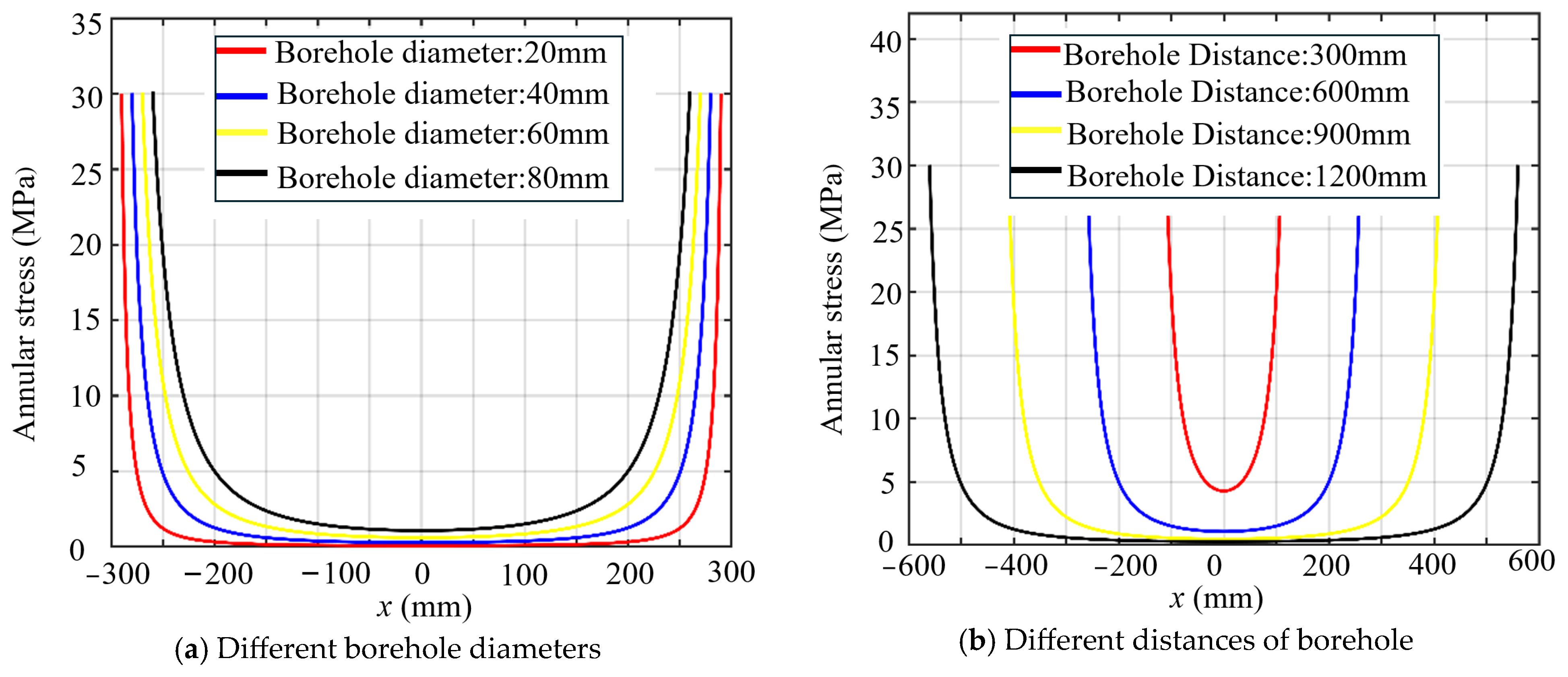
2.1. Theoretical Analyses of Rock Models with Single and Double Expansion Holes

The static expansion fracturing process of a coal rock mass can be divided into the linear elasticity stage and the non-linear elasticity stage [32]. In the initial stage of rock mass expansion, the mechanical behaviors of the rock material are in line with the force law of linear elasticity; the expansion stress of the rock medium around the hole can be calculated by the elasticity theory of a thick-walled cylinder model, as shown in Figure 1a. Under the internal expansion pressure of an SCA, the deformation and stress around the coal rock hole in the radial and tangential directions can be calculated by Equations (1) and (2) [33].
σ r σ θ = P e x R 2 ( R + d ) 2 R 2 1 ( R + d ) 2 r 2
where Pex is the expansion pressure; R is the inner diameter of the cylinder; and d is the wall thickness of the cylinder.
When d + R , the following can be assumed:
σ r σ θ = P e x R 2 / r 2
In practical applications, rock fragmentation under internal pressure is achieved through multiple borehole arrangements, where the annular stress along the connection line of adjacent borehole governs the rock fracture initiation. As shown in Figure 1b, for a two-borehole model with radius R spaced at distance L , the annular stress along the central axis is expressed as follows:
σ θ = P e x R 2 ( L + x ) 2 + P e x R 2 ( L x ) 2
The influence of the hole spacing and diameter of the adjacent boreholes on annular stress is shown in Figure 2. As the hole spacing and hole diameter size change, the maximum value of the annular stress occurs along the drill hole wall between the adjacent drill holes, and the annular stress at the center line between two drill holes is the smallest. When the hole spacing increases, the annular stress at the center of the drill line decreases, and the ability of the expander to fracture and penetrate becomes weaker under multiple expansion drillholes; when the hole diameter increases, the annular stress at the center of the drill line becomes larger, and the ability of the expander to fracture and penetrate increases under multiple expansion drillholes. Therefore, in practical engineering applications, hole size and spacing design play a crucial role in the final fracturing effect of a rock mass.

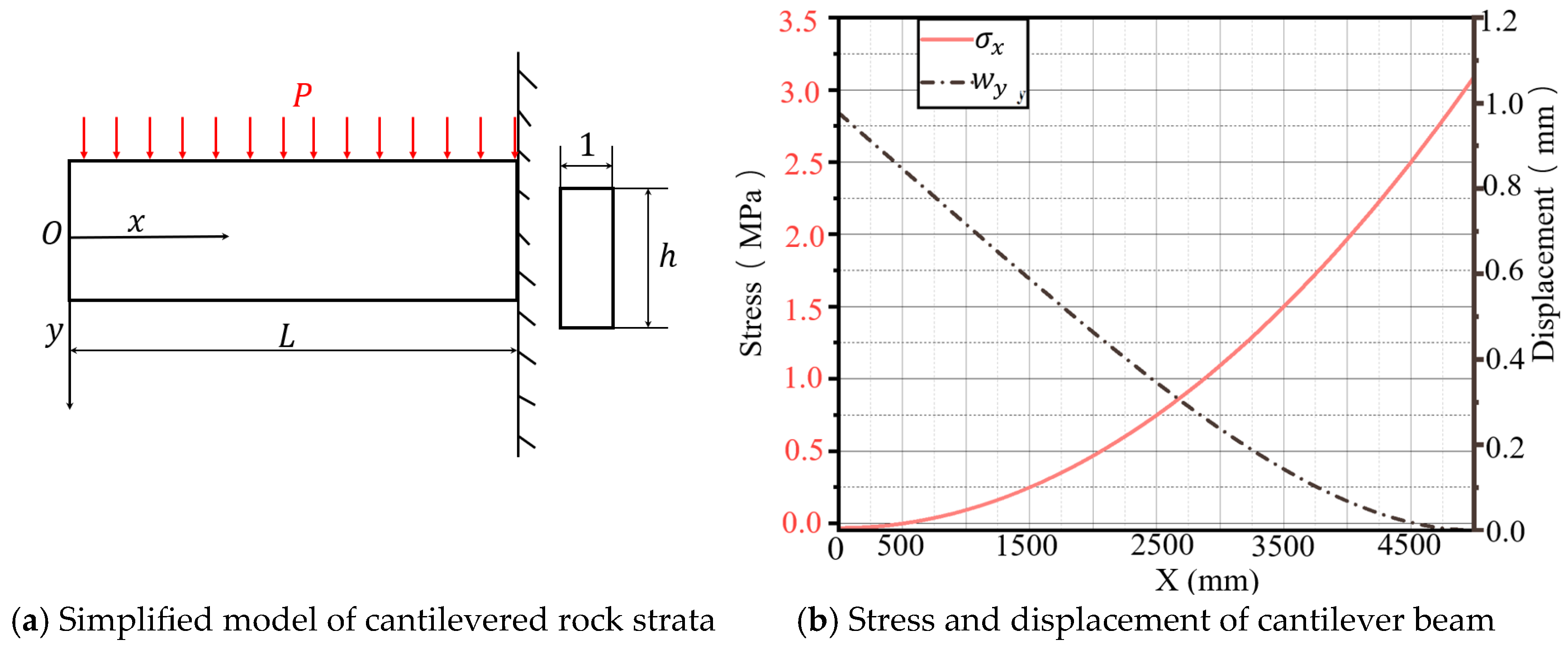
2.2. Theoretical Analyses of the Cantilevered Rock Strata Model

Considering the roof as an elastic medium, it is subjected to a transverse uniform load P (including self-weight); this mechanical model is shown in Figure 3a. According to the elasticity mechanics, the stress and displacement of the cantilever beam at any point are as follows:
σ x = P x 2 y 2 I + P 2 I 2 3 y 3 h 2 10 y w y = P L x 2 24 E I L + x 2 + 2 L 2
where σ x is the bending stress; w y is the deflection; P is the uniform load acting on the cantilever beam; I is the inertia moment of the cantilever beam; and E is the elasticity modulus of the cantilever beam.
If P = 1 MPa, h = 2 m, L = 5 m, and E = 20 GPa, then the stress and deflection are shown in Figure 3b. The results indicate that the bending stress   σ x increases gradually with the growth of x and reaches its maximum value at the restrained end of the cantilever beam. The cantilever beam deflection achieves its maximum value at the free end. Based on the analysis in Figure 3b, the spatial evolution of bending stress shows a linear distribution of axial bending stress σx in the cantilever beams; bending stress at the free end (x = 0 mm) is 0 Mpa, and bending stress σx at the constrained end (x = 5000 mm) is 3.0 Mpa, satisfying the free surface boundary condition.

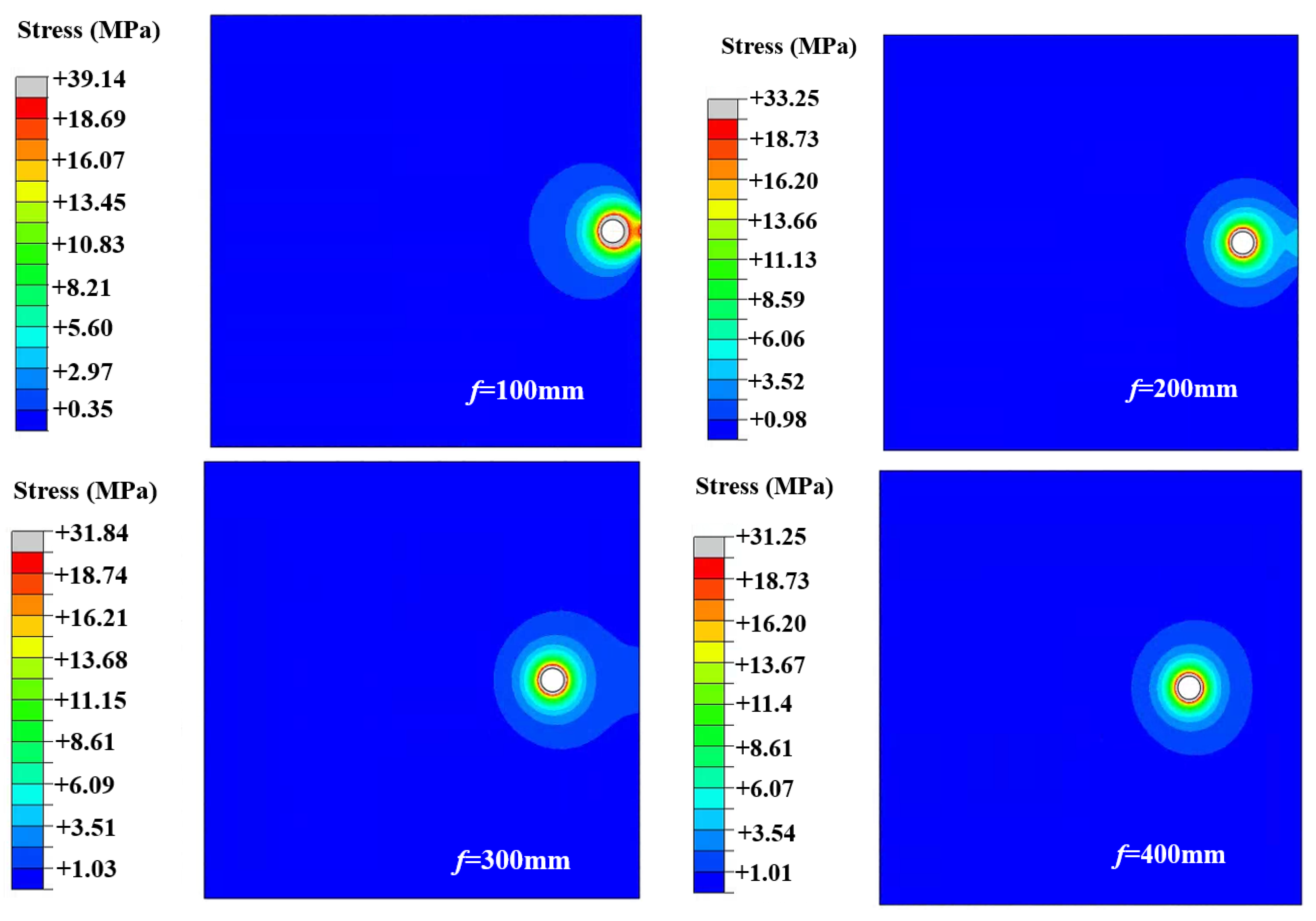
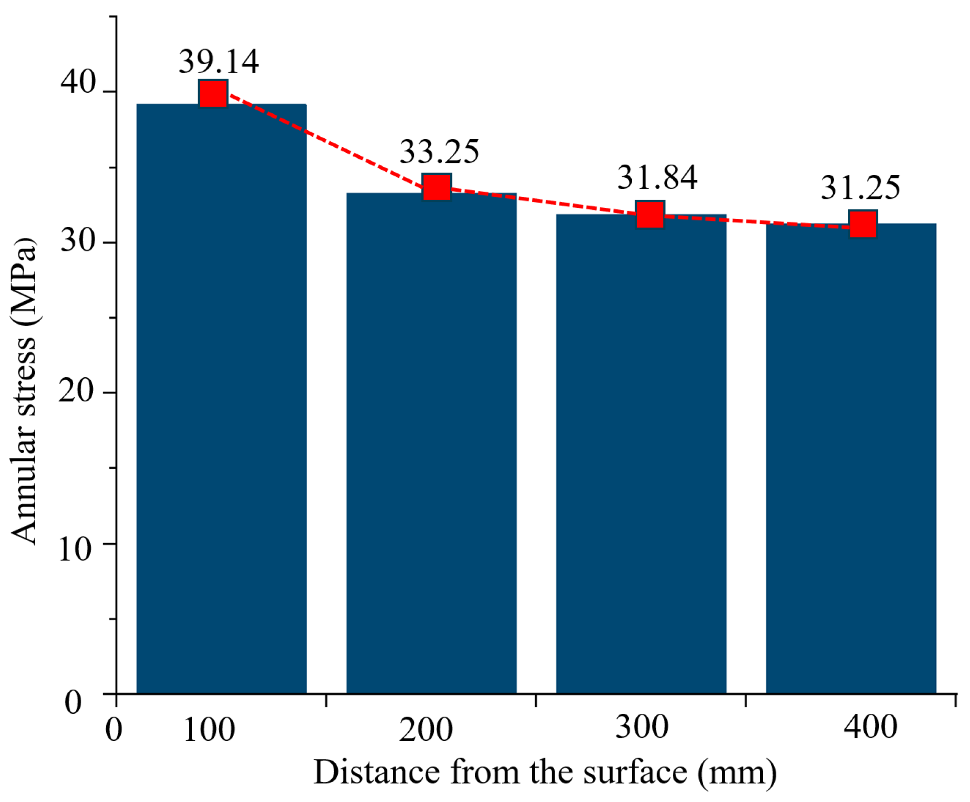
2.3. Simulation Analysis of Free Surface Effects

Given that the splitting problem of an infinitely large rock object is difficult, under the action of SCA expansion pressure, the influences of free surface on the stress concentration and fracturing effect of a large-scale rock mass are important. In this paper, for an eccentric expansion hole rock mass model, the distance from the borehole center to the free surface is defined as f and is varied as 100 mm, 200 mm, 300 mm, and 400 mm. The borehole concentration coefficients of the annular expansion stress in a rock mass are investigated by a simulation using the ABAQUS 2019. ABAQUS software is a powerful engineering simulation finite element software suite with reliable decomposition results, ranging from simple linear analyses to complex nonlinear problems [31]. Given the rock mechanical parameters—elastic modulus E = 20 Gpa; Poisson’s ratio μ = 0.2; borehole radius R = 40 mm; and internal expansive pressure Pex = 30 Mpa—simulations were conducted to investigate the stress distribution patterns. By simulation, the stress distribution cloud diagram and annular stress values of a rock mass model with different free surface distances are shown in Figure 4.
The simulation results are extracted and counted in Figure 5. At a free surface distance f = 100 mm, the annular stress of the proximal free surface (y = 0) reaches 39.14 MPa, yielding a stress concentration factor Kt = 1.3 (normalized to the internal expansive pressure Pex = 30 MPa). A progressive weakening of stress concentration is observed with the increasing f. At f = 200 mm, annular stress reduces to 33.25 MPa, representing a 15.05% decrease compared to the f = 100 mm case. At f = 400 mm, annular stress further diminishes to 31.25 MPa, achieving a 20.16% reduction relative to the baseline scenario.
Obviously, the phenomenon of stress concentration occurs at the position closest to the free surface of the borehole, that is, at y = 0, and the degree of stress concentration increases sharply with the decrease in distance f from the center of the borehole to the free surface. Therefore, in practical engineering applications, the distance from the center of the borehole to the free surface can be reasonably designed to fully utilized the cracking ability of the expansion agent.

3. Stress Distribution in the Cantilevered Roof

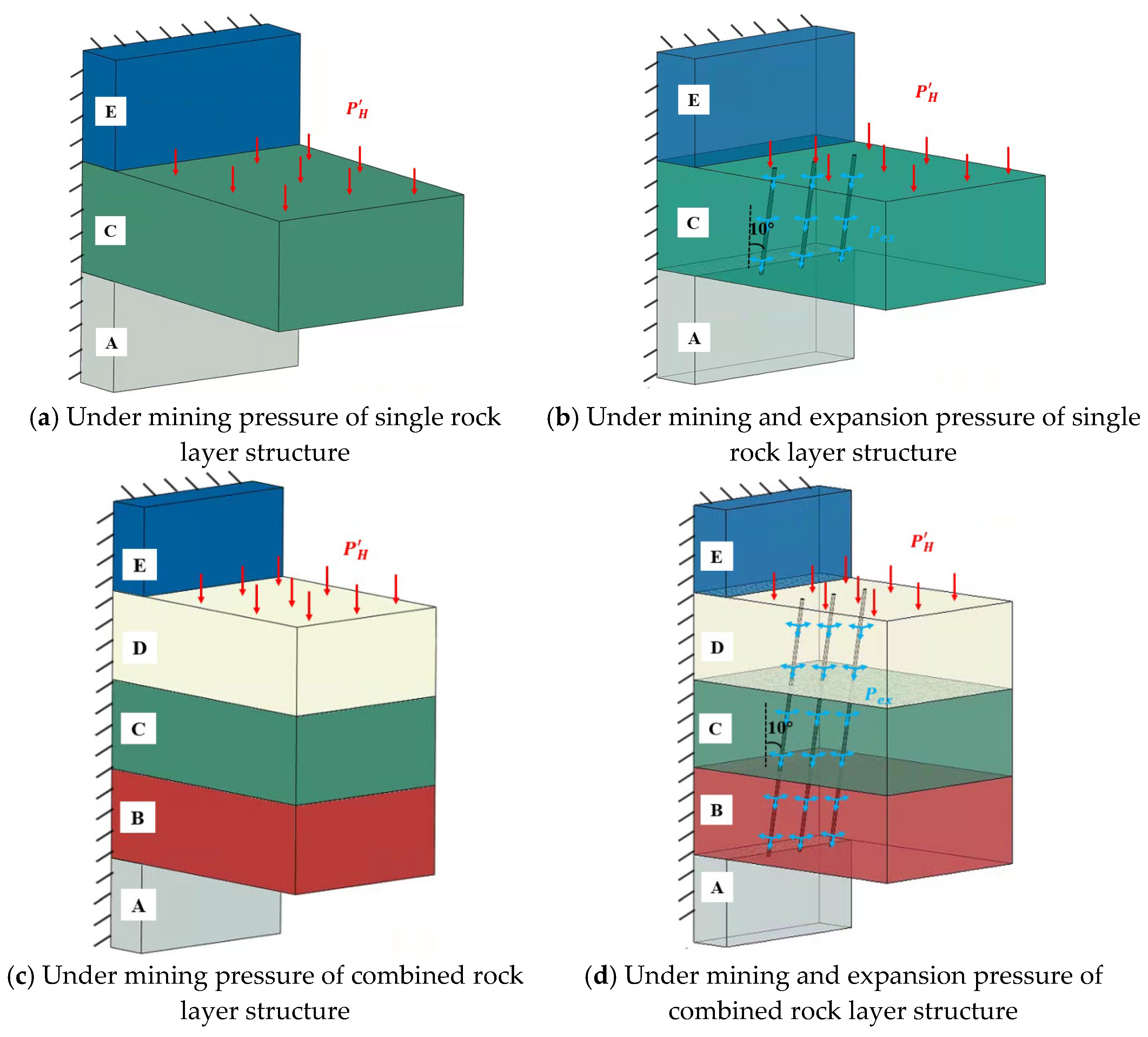
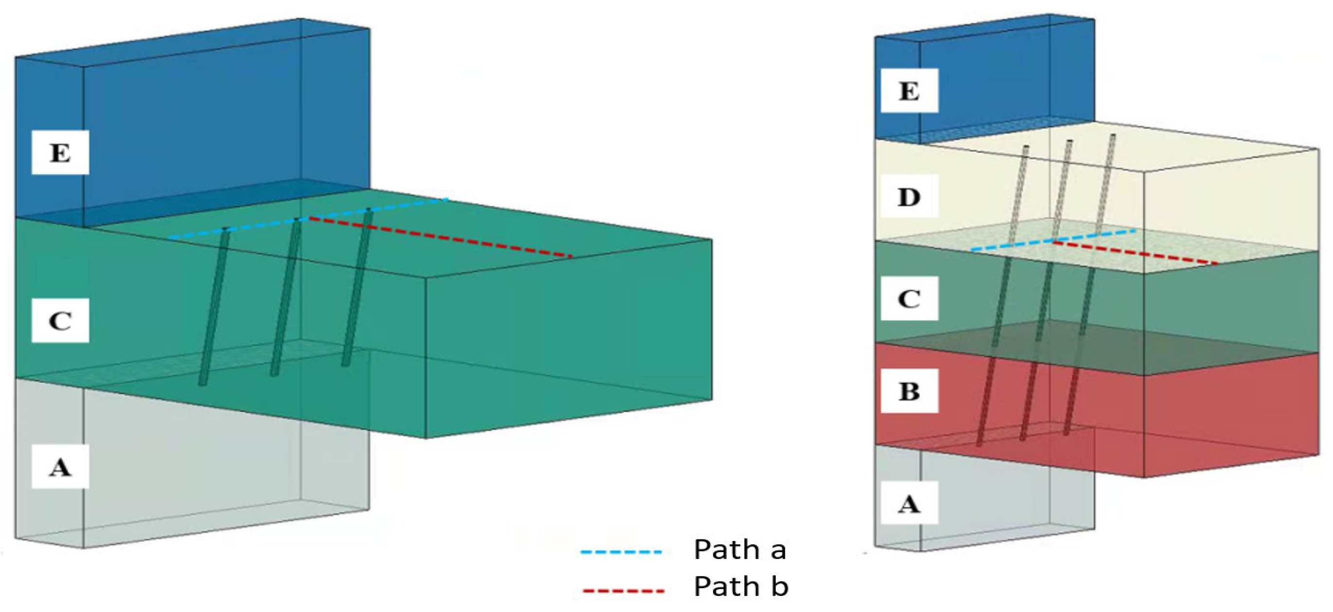
3.1. Simulation Scheme of the Cantilever Roof

In this section, simulations of the roof strata are investigated to reveal the fracturing mechanisms of rock strata for the cantilever beam models of single and combined rock layers. Under mining pressure only, as shown in Figure 6a, the single layer cantilever beam model involves three layers, A, C, and E, where the bottom and back surfaces of A, the top and back surfaces of E, and the back surface of C are fully restrained; a uniform load of 1 MPa is applied to the top surface of C. As shown in Figure 6c, the combined layer cantilever beam model involves five layers, namely, A, B, C, D, and E (the parameters of the layers are shown in Table 1), where the bottom and back surfaces of A, the top and back surfaces of E, and the back surfaces of B, C, and D are fully restrained. A uniform load of 1 MPa is applied to the top surface. Under the combined action of mining and expansion pressure, three rows of drill holes through the B, C, and D rock layers are added; the diameter of the drill holes is 75 mm, the spacing between the rows is 1 m, and the inclination angle of the drill holes is 10° biased towards the mining area, an expansion pressure of 30 MPa was applied to the borehole’s inner wall. Based on the above schemes, the corresponding simulations on the mechanical characteristics of the cantilever roof are conducted and analyzed.

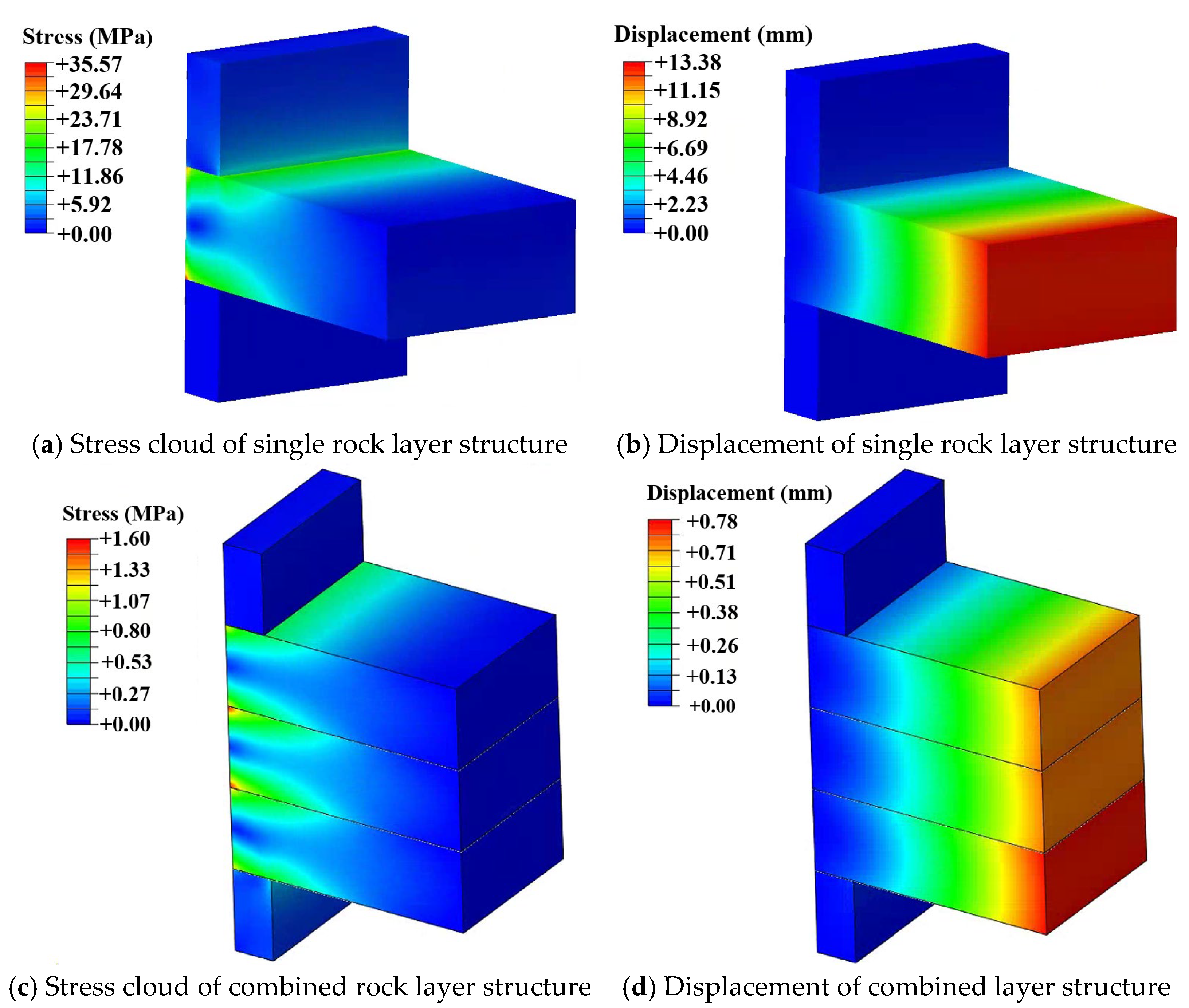
3.2. Simulation Analysis of the Cantilever Roof Under Mineral Pressure Only

The corresponding simulation results for the mechanical characteristics of the cantilever beam models of single and combined rock layers under mining pressure are shown in Figure 7. From Figure 7a,b, the comparison of stress and displacement in a single rock cantilever beam under mining pressure reveals distinct patterns. The stress ranges from a maximum of 35.57 Mpa in the peak stress zone near the constraint end to a minimum of 184 Pa near the free surface, indicating significant stress concentration at the constraint end and negligible stress at the free surface. Similarly, the displacement varies from 13.38 mm at the free end to 0.0 mm at the constrained end, demonstrating that maximum displacement occurs at the free end and diminishes to zero towards the constrained end. These results highlight the critical areas of stress concentration and displacement distribution in the rock cantilever beam under mining pressure. From Figure 7c,d, the comparison of stress and displacement in the composite rock cantilever beams under mining pressure shows notable differences from the single rock beams. The stress ranges from a maximum of 1.60 Mpa in the interlayer contact zone, indicating slight stress concentration, to a minimum of 871 Pa in the lower rock mass, demonstrating effective stress dispersion. Displacement is significantly reduced, with a maximum of 0.78 mm at the free end and zero at the constrained end. This reduction highlights the interlayer synergistic effect, which effectively suppresses deformation as compared to the single rock beams. These findings emphasize the improved stress distribution and deformation control in composite rock cantilever structures under mining pressure.

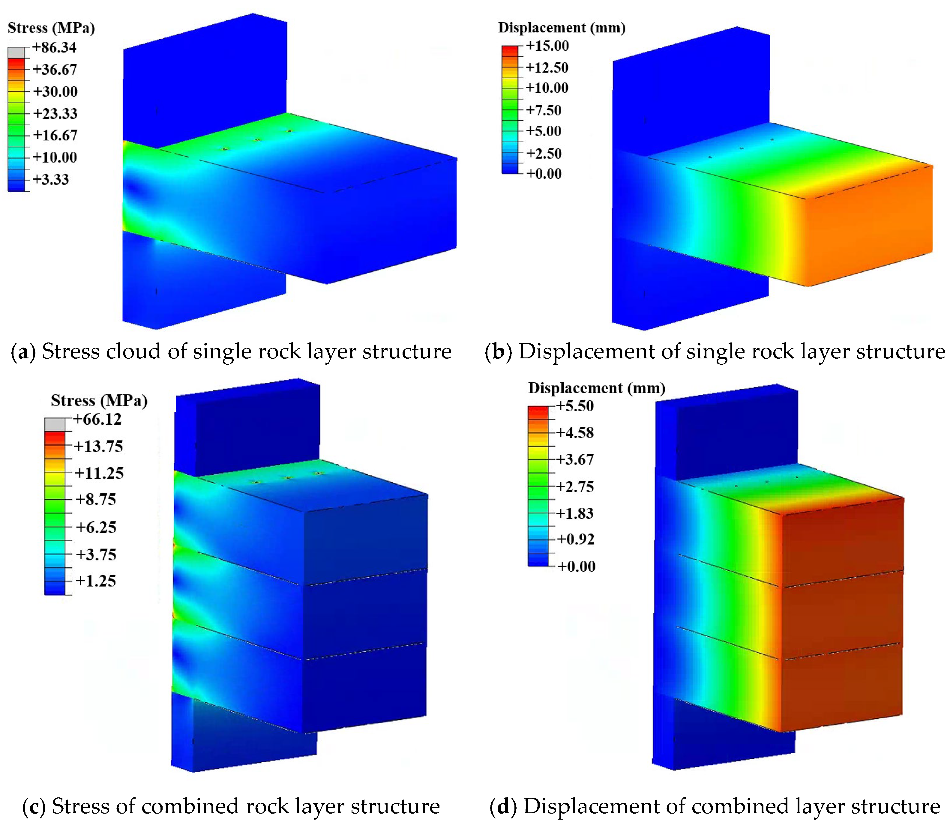
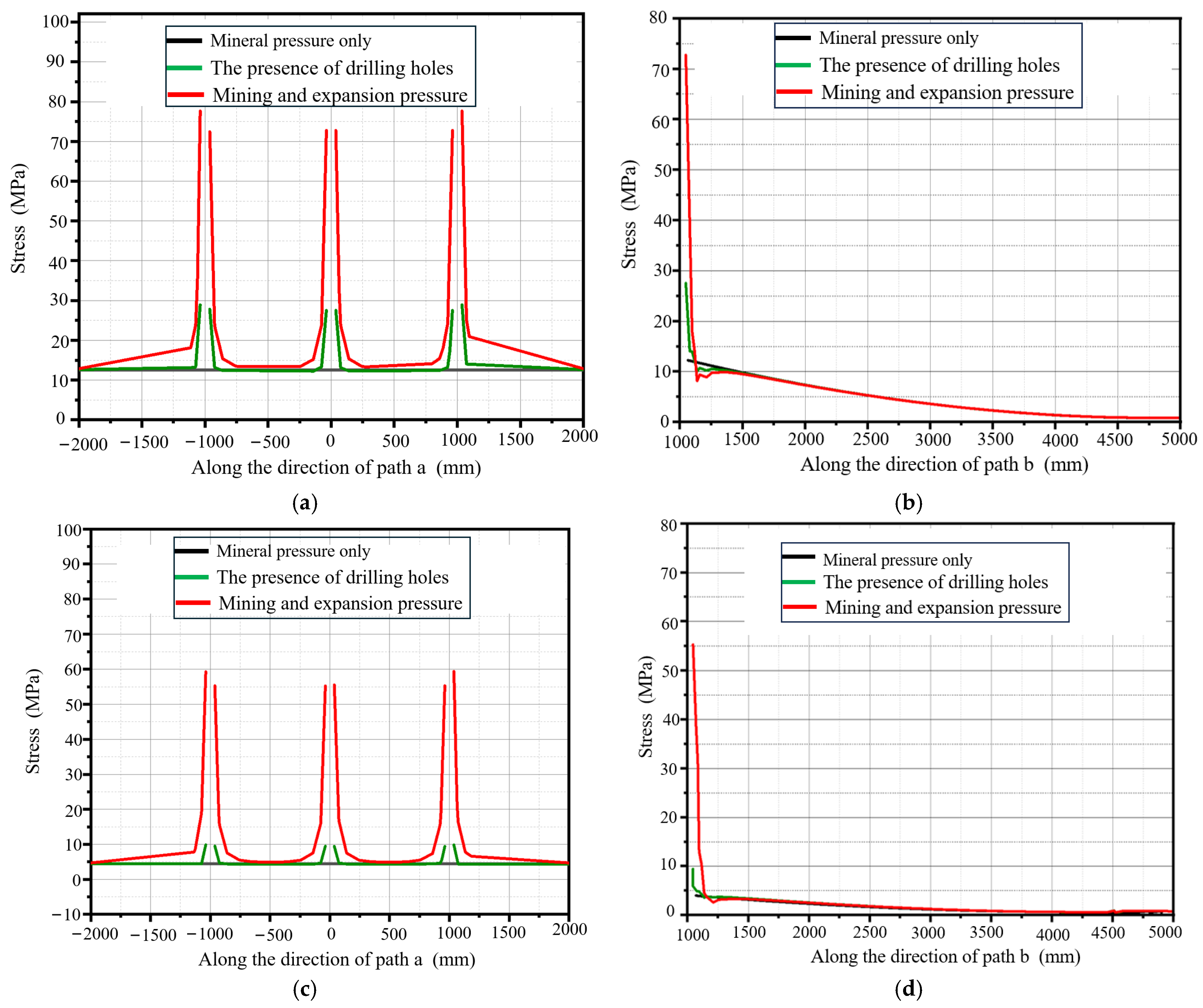
3.3. Simulation Analysis of the Cantilever Roof Under the Mining and Expansion Pressure

The stress and displacement cloud of a cantilever roof under the combined action of mining and expansion pressure are shown in Figure 8. From Figure 8a,b, for the single rock cantilever model, the simulation results reveal significant stress concentration and displacement under the combined effects of mining and expansion pressure. Stress peaks at 86.34 MPa in the high-stress zone around the borehole edge and drops to 184 Pa near the free surface, indicating intense localized stress due to the expansion agent. Displacement reaches 15.00 mm at the free end, gradually decreasing to zero at the constrained end, demonstrating pronounced deformation under the combined forces. From Figure 8c,d, under combined effects of mining and expansion pressure, the composite rock cantilever beams exhibit improved stress distribution and deformation control. Stress concentrates at 66.12 MPa in the interlayer contact zone but remains extremely low (184 Pa) in the lower rock mass. Displacement is significantly reduced to 5.50 mm at the free end, with zero displacement at the constrained end, highlighting the role of the interlayer synergistic effect in suppressing deformation compared to single rock structures.
Furthermore, the stress doubling effect of a single rock layer significantly changes the stress distribution around a borehole due to expansion pressure (Pex = 30 MPa). Peak stress reaches 86.34 MPa, which is 242.73% of the mining pressure condition (35.57 MPa) and 156.98% of the compressive strength of the rock mass ( σ 0 = 55 MPa). For multi-layer coordinated deformation, the peak stress reaches 66.12 MPa, which is 413.25% of the mining pressure condition (1.60 MPa).

3.4. Comparison of Three Working Conditions

To further investigate the mechanical state of the roof strata, the stress and displacement of paths a and b in layers B, C, and D are extracted. Two paths, a and b, are set as monitoring points on rock layer C in the single formation and combined formation cantilever beam models, with path a in the direction of the drilling hole arrangement and path b in the direction of workforce advancement, as shown in Figure 9.
For the single formation cantilever beam model, the stress distributions along paths a and b are shown in Figure 10a,b; for the combined formation cantilever beam structure, the stress distribution along paths a and b are shown in Figure 10c,d. For both the single formation and combined formation cantilever beam structures, the stress values near the drill holes where both the mining and expansion pressures act are much higher as compared to those where only the mining pressure is applied, suggesting that the expansion agent is more likely to achieve roof breakage under mining pressure. Moreover, the stress along the drill hole wall close to the free surface is significantly higher than that of the middle drill hole, which indicates that the roof starts to break from the drill hole closest to the free surface and then expands to the middle. Furthermore, the stress along the hole wall in the direction of path a is significantly higher than that along path b, which indicates that the roof breakage is likely to occur in the direction of the drill hole arrangement. For path a (direction of maximum principal stress) of the single formation cantilever beam structure, the stress at the midpoint increases sharply from 12.3 MPa to 72.8 MPa; the peak stress of path b (direction of minimum principal stress) increases from 12.25 MPa to 72.75 MPa. For the combined formation cantilever beam structure, the stress at the midpoint increases sharply from 4.4Mpa to 59.33 MPa; the peak stress of path b (direction of minimum principal stress) increases from 4 MPa to 55.34 MPa.

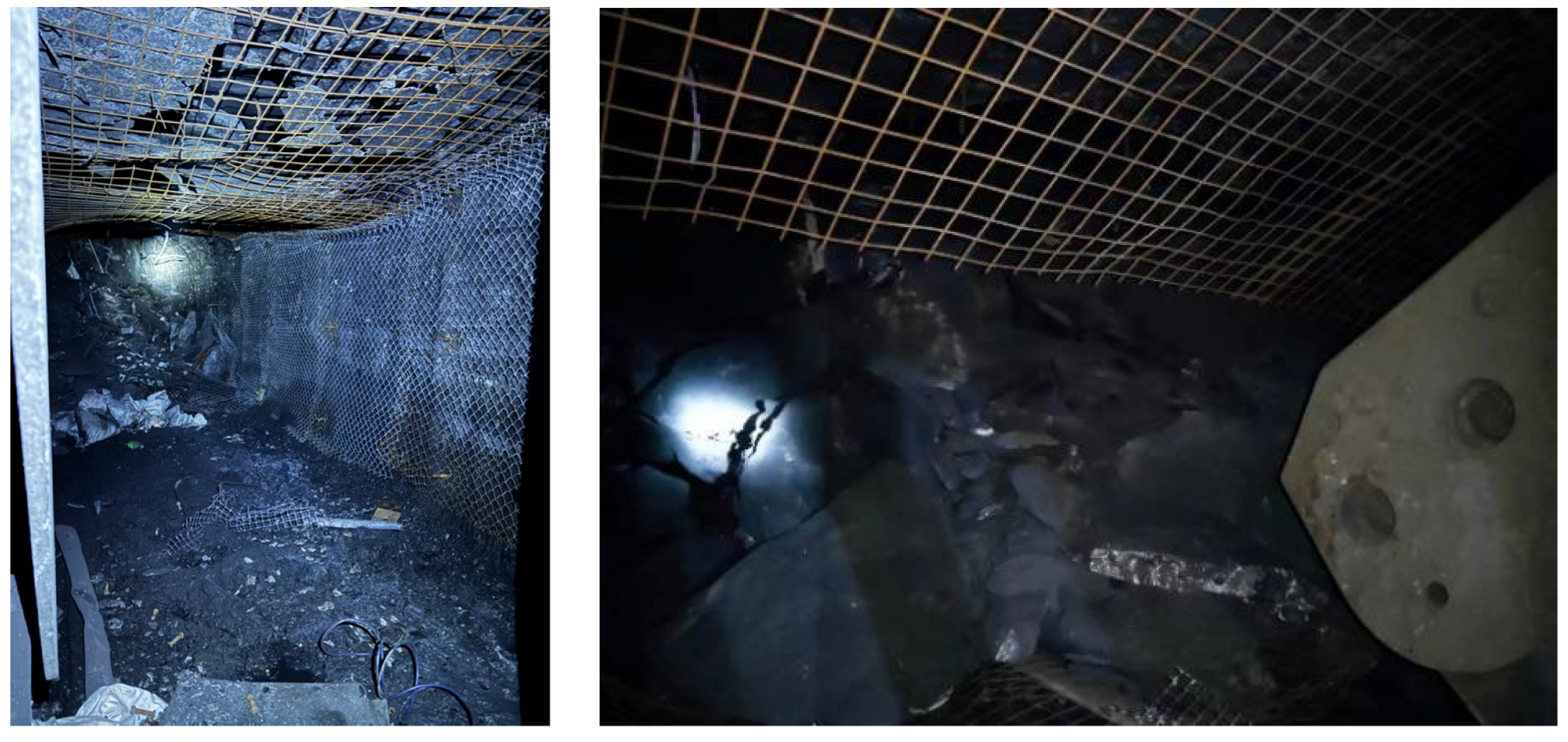
4. Engineering Application

During the mining process, ensuring roof stability and effective hanging roof control is crucial for safe production. To improve roof management and reduce mining risk, a static fracturing project is carried out to regulate the hanging roof in a certain coal mine. The mine adopts once mining full-height technology; the average thickness of the coal seam is 2.62 m. The borehole design scheme is shown in Figure 11, where three boreholes are constructed in each row, the row spacing of the boreholes is set to 6 m, and the borehole inclination angle is 10° and is biased towards the goaf. The roof pre-splitting holes are constructed using a ZDY-3500L drill rig. The drill pipe model is Φ63 × 1000 mm, and the drill bit model is Φ75 mm.
As shown in Figure 12, after completing the borehole construction, water and powdered expansive agent are rapidly and uniformly mixed at a water–cement ratio of 0.34. Subsequently, the well-mixed slurry is injected into the boreholes using a grouting pump. When the return pipe shows the return of the slurry or the injection volume exceeds 30% of the calculated amount, the grouting pump is immediately turned off, and the injection is stopped. The expansive agent injected into the boreholes undergoes a hydration reaction, causing the crystals to deform. As time goes by, a huge expansive pressure will be generated, continuously applying pressure to the borehole wall.
After static fracturing construction, the hanging roof situation of the goaf is tracked and observed. As shown in Figure 13, the hanging roof area of the goaf is significantly reduced, and the ideal state after roof caving is basically achieved. There is no cavity between the caved roof and the support tail beam. The hanging roof range is generally maintained at seven to eight rows of bolts longitudinally, and the hanging roof area does not exceed 20 m2.

5. Conclusions

(1)
The optimization study of expansion pressure parameters shows that the stress doubling effect of a single rock layer significantly changes the stress distribution around borehole due to expansion pressure (Pex = 30 MPa). The peak stress reaches 86.34 MPa, which is 242.73% of the mining pressure condition (35.57 MPa) and 156.98% of the compressive strength of the rock mass ( σ 0 = 55 MPa). For multi-layer coordinated deformation, the peak stress reaches 66.12 MPa, which is 413.25% of the mining pressure condition (1.60 MPa). An on-site industrial application verified technical reliability; after adopting the drilling scheme with a 75 mm diameter and a 6 m spacing, the hanging roof area at the end of the mining face is reduced to below 20 m2.
(2)
At a free surface distance f = 100 mm, the annular stress of the proximal free surface (y = 0) reaches 39.14 MPa, yielding a stress concentration factor Kt = 1.3 (normalized to the internal expansive pressure Pex = 30 MPa). A progressive weakening of stress concentration is observed with increasing f. At f = 200 mm, annular stress reduces to 33.25 MPa, representing a 15.05% decrease compared to the f = 100 mm case. At f = 400 mm, stress further diminishes to 31.25 MPa, achieving a 20.16% reduction relative to the baseline scenario.
(3)
The cantilever beam model reveals the gradient evolution law of roof fracture. The results indicate that bending stress   σ x increases gradually with the growth of x and reaches its maximum value at the restrained end of the cantilever beam—the compressive stress. The cantilever beam deflection achieves its maximum value at the free end.
In summary, the engineering application using a perfusion-type expansive agent for the static fracturing of the roof at the end of a mining face improved the hanging roof situation and reduced the end-head support pressure. Future studies could optimize the use of expansive agents and explore their adaptability under different geological conditions to better serve the coal mining industry.

Author Contributions

Conceptualization, R.Y. and Q.Z.; Methodology, R.Y. and Q.Z.; Software, H.L. and P.Z.; Investigation, C.F. and H.L.; Writing—original draft, H.L. and Q.Z.; Writing—review and editing, C.F. and H.L. All authors have read and agreed to the published version of the manuscript.

Funding

This research was the National Key Research and Development Project of China: 2023YFC3007203; National Natural Science Foundation of China: 52174109; Program for Innovative Research Team (in Science and Technology) in University of Henan Province: 22IRTSTHN005; Key Research and Development Project of Henan Province: 242102240029; and Key Research Project of Institutions of Higher Education in Henan Province: 24A580001.

Data Availability Statement

The original contributions presented in this study are included in the article. Further inquiries can be directed to the corresponding authors.

Conflicts of Interest

The authors declare no conflict of interest.

References

  1. Debjeet, M.; Roy, P.N.S.; Manoj, K. Roof fall threat analysis using fractal pattern recognition and neural network over mine microseismicity in a Central Indian longwall panel overlain by massive sandstone roof. Geosyst. Geoenviron. 2023, 2, 100138. [Google Scholar]
  2. Yang, J.; Zheng, K.; Wang, Z.; Pang, N. Technology of weakening and danger-breaking dynamic disasters by hard roof. J. China Coal Soc. 2020, 45, 3371–3379. [Google Scholar]
  3. Song, Y. Techniques for Controlling Hard and Hard-to-Rise Roof Slabs in Coal Seams; Coal Industry Publishing House: Beijing, China, 2002; pp. 67–69. [Google Scholar]
  4. Fang, X.; Hao, X.; Lan, Y. Determination of reasonable forced caving interval in shallow-buried seam with hard and thin bedrock. Chin. J. Rock Mech. Eng. 2010, 29, 388–393. [Google Scholar]
  5. Huang, B.; Liu, J.; Zhang, Q. The reasonable breaking location of overhanging hard roof for directional hydraulic fracturing to control strong strata behaviors of gob-side entry. Int. J. Rock Mech. Min. Sci. 2018, 103, 1–11. [Google Scholar] [CrossRef]
  6. Marek, J.; Andrzej, H.; Mateusz, Ć. Directional Hydraulic Fracturing (DHF) of the Roof, as an Element of Rock Burst Prevention in the Light of Underground Observations and Numerical Modelling. Energies 2021, 14, 562. [Google Scholar] [CrossRef]
  7. Xia, B.; Zhang, X.; Yu, B.; Jia, J. Weakening effects of hydraulic fracture in hard roof under the influence of stress arch. Int. J. Min. Sci. Technol. 2017, 28, 951–958. [Google Scholar] [CrossRef]
  8. Klishin, I.V.; Opruk, Y.G.; Teleguz, S.A.; Galkin, A.V. Spectral acoustic and seismological monitoring of enclosing rock condition in the face area during roof softening by means of directional hydraulic fracturing (DHF). IOP Conf. Ser. Earth Environ. Sci. 2018, 206, 012023. [Google Scholar] [CrossRef]
  9. Wang, C.; Zheng, K.; Wang, H.; Li, Y.; Wang, L. Comprehensive treatment technology of hydraulic fracturing in initial mining of the first mining face under hard roof. Coal Eng. 2023, 55, 63–69. [Google Scholar]
  10. Shakib, T.; Shahri, A. Analysis of hydraulic fracturing in fractured reservoir: Interaction between hydraulic fracture and natural fractures. Life Sci. J. 2012, 9, 1854–1862. [Google Scholar]
  11. Matsui, K.; Shimada, H.; Anzwar, H.Z. Acceleration of massive roof caving in a longwall gob using a hydraulic fracturing. In Proceedings of the 4th International Symposium on Mining Science and Technology, Beijing, China, 29–31 August 1999. [Google Scholar]
  12. Sawmliana, C.; Roy, P.P. A New Blastability Index for Hard Roof Management in Blasting Gallery Method. Geotech. Geol. Eng. 2012, 30, 1357–1367. [Google Scholar] [CrossRef]
  13. Mondal, A.; Pathrikar, A.; Karekal, S. Phase-Field Based Peridynamics Implementation to Model Blast-Induced Fracture in Brittle Solids. Rock Mech. Rock Eng. 2024, 57, 5685–5703. [Google Scholar] [CrossRef]
  14. Slavko, T.; Veljko, L. Rock fracturing mechanisms by blasting. Podzemn. Rad. 2018, 32, 15–31. [Google Scholar]
  15. Zhang, Z. Failure of hanging roofs in sublevel caving by shock collision and stress superposition. J. Rock Mech. Geotech. Eng. 2016, 8, 886–895. [Google Scholar] [CrossRef]
  16. Gautam, A.; Kumar, A.; Ram, S.; Skrzypkowski, K.; Zagórski, K.; Zagórska, A.; Madziarz, M.; Migda, K. Strata Control by Roof Blasting for Bord and Pillar Mining Method in Mechanized Depillaring Panels. Appl. Sci. 2025, 15, 1403. [Google Scholar] [CrossRef]
  17. Ren, X.; Guo, J.; Zhang, B.; Xi, Z.; Lu, C.; Li, H. Mine pressure manifestation law of dynamic pressure roadway with multilayer hard roof and roof cutting control technology of deep and shallow hole combination blasting. Min. Res. Dev. 2024, 44, 48–55. [Google Scholar]
  18. Enrico, C.D.; Andrea, L.; Andrea, T. A novel extension of the SYNTHSEP methodology for the optimal synthesis and design of supercritical CO2 cycles in waste heat recovery applications. Energy Convers. Manag. 2023, 276, 116535. [Google Scholar]
  19. Sampath, K.; Perera, M.; Ranjith, P.; Ranjith, P.G.; Matthai, S.K. CO2 interaction induced mechanical characteristics alterations in coal: A review. Int. J. Coal Geol. 2019, 204, 113–129. [Google Scholar] [CrossRef]
  20. Hol, S.; Spiers, J.C.; Peach, J.C. Microfracturing of coal due to interaction with CO2 under unconfined conditions. Fuel 2012, 97, 569–584. [Google Scholar] [CrossRef]
  21. Kiyama, T.; Nishimoto, S.; Fujioka, M.; Xue, Z.; Ishijima, Y.; Pan, Z.; Connell, L.D. Coal swelling strain and permeability change with injecting liquid/supercritical CO2 and N2 at stress-constrained conditions. Int. J. Coal Geol. 2011, 85, 56–64. [Google Scholar] [CrossRef]
  22. Lu, G. Study on CO2 gas-phase fracturing for coal seam roof weakening in fully mechanised top coal caving face. Coal Eng. 2017, 49, 58–59+62. [Google Scholar]
  23. Raskildinov, B.U. Increasing the effectiveness of blasting in underground mines. In Proceedings of the 17th International Mining Congress and Exhibition of Turkey, Ankara, Turkey, 19–22 June 2001. [Google Scholar]
  24. Zhang, W.; Cao, L.; Zhang, D.; Hu, Y.; Chang, J.; Zhang, Z. Deformation and Fracture Mechanisms of Thick Hard Roofs in Upward Mining Coalfaces: A Mechanical Model and Its Validation. Appl. Sci. 2024, 14, 10278. [Google Scholar] [CrossRef]
  25. He, Y.; Huang, Q. Simulation Study on Spatial Form of the Suspended Roof Structure of Working Face in Shallow Coal Seam. Sustainability 2023, 15, 921. [Google Scholar] [CrossRef]
  26. Liu, H.; Hao, C.; Han, Z.; Liu, Q.; Wang, H.; Liang, J.; Zhang, D. Study on the Mechanism of a Hanging Roof at a Difficult Caving End in a Fully-Mechanized Top Coal Caving Face. Sustainability 2023, 15, 812. [Google Scholar] [CrossRef]
  27. Zhu, X.; Zhai, C.; Yu, X.; Xu, J.; Sun, Y.; Cong, Y.; Zheng, Y.; Tang, W.; Chen, A. Fracture damage characteristics of hard roof with different bedding angles induced by modified soundless cracking agents. Eng. Fract. Mech. 2023, 289, 109387. [Google Scholar] [CrossRef]
  28. Eugene, S.; Wu, W. Experimental analysis of expansion and stress generation of the static cracking agent on supporting beam. Energy Build. 2023, 298, 113548. [Google Scholar] [CrossRef]
  29. Li, C.; He, S.; Hou, W.; Ma, D. Experimental study on expansion and cracking properties of static cracking agents in different assembly states. Int. J. Min. Sci. Technol. 2022, 32, 1259–1272. [Google Scholar] [CrossRef]
  30. Wu, S.; Zhai, C.; Xu, J.; Qin, L.; Sun, Y.; Dong, R. The performance of soundless cracking agents for weakening rock roof under different notch angles. Arab. J. Geosci. 2019, 12, 1–13. [Google Scholar] [CrossRef]
  31. Yuan, R.; Lian, Z.; Zhang, Q.; Li, M.; Li, H.; Li, Y.; Wu, W. Rock Fracturing Characteristics and Roadway Expansion Application of Static Crushing Agent under Multi-Row Drilling Condition. Appl. Sci. 2024, 14, 9032. [Google Scholar] [CrossRef]
  32. Jin, Z.; Liao, H.; Zhu, W. Splitting mechanism of rock and concrete under expansion pressure. Chin. J. Rock Mech. Eng. 1989, 1989, 19–26. [Google Scholar]
  33. Salençon, J.; Halphen, B. Calcul des structures Anélastiques. In Élasto-Plasticité; Presses de l’École des Ponts ParisTech: Puteaux, France, 1985. [Google Scholar]
Figure 1. Rock models with single and double expansion holes.
Processes 13 01275 g001
Figure 2. Effects of hole diameter and hole spacing on annular stresses.
Processes 13 01275 g002
Figure 3. Roof model and stresses and deflections of the cantilever beam.
Processes 13 01275 g003
Figure 4. Stress clouds at different free surface distances.
Processes 13 01275 g004
Figure 5. Annular stress values on the free surface.
Processes 13 01275 g005
Figure 6. Cantilever beam models of single layer and combined layers.
Processes 13 01275 g006
Figure 7. Stress and displacement cloud of cantilever structure under mining pressure.
Processes 13 01275 g007
Figure 8. Stress and displacement clouds of the cantilever model under the combined action of mining and expansion pressure.
Processes 13 01275 g008
Figure 9. Schematic layout of monitoring points in the cantilever roof model.
Processes 13 01275 g009
Figure 10. Stress distribution in single cantilever structure and combined cantilever structure: (a,b) single formation cantilever structure; (c,d) combined formation cantilever structure.
Processes 13 01275 g010
Figure 11. Borehole design diagram.
Processes 13 01275 g011
Figure 12. On-site mixing and roof hole sealing of the expansive agent.
Processes 13 01275 g012
Figure 13. The roof situation before and after static fracturing.
Processes 13 01275 g013
Table 1. Rock parameters.
Layer NumberModulus of Elasticity (Gpa)Poisson’s RatioSize (m)
A100.21 × 4 × 2
B150.26 × 4 × 2
C200.26 × 4 × 2
D150.26 × 4 × 2
Disclaimer/Publisher’s Note: The statements, opinions and data contained in all publications are solely those of the individual author(s) and contributor(s) and not of MDPI and/or the editor(s). MDPI and/or the editor(s) disclaim responsibility for any injury to people or property resulting from any ideas, methods, instructions or products referred to in the content.

