Article

Enhancing the Quality and Sustainability of Laser Cutting Processes in Laser-Assisted Manufacturing Using a Box–Behnken Design

by
Omid Mehrabi
1,*,
Zeinab Malekshahi Beiranvand
2,
Fakhir A. Rasoul
3 and
Mahmoud Moradi
4,*
1
Department of Mechanical Engineering, Esfarayen University of Technology, Esfarayen 96619-98195, Iran
2
Department of Materials, Faculty of Engineering, Arak University, Arak 38481-77584, Iran
3
Department of Air-Conditioning and Refrigeration Technical Engineering, College of Technical Engineering, Al-Kitab University, Kirkuk 36001, Iraq
4
Faculty of Arts, Science and Technology, University of Northampton, Northampton NN1 5PH, UK
*
Authors to whom correspondence should be addressed.
Processes 2025, 13(5), 1279; https://doi.org/10.3390/pr13051279
Submission received: 25 March 2025 / Revised: 13 April 2025 / Accepted: 21 April 2025 / Published: 23 April 2025
(This article belongs to the Special Issue Progress in Laser-Assisted Manufacturing and Materials Processing)

Abstract

:
This study aims to examine and optimize CO2 laser cutting parameters—namely, laser power, cutting speed, and focal plane position—when applied to polypropylene material using an experimental methodology. This research aims to improve cutting quality, increase cutting speed, and reduce waste while adhering to sustainability objectives. To achieve these goals, a comprehensive experimental approach was employed, incorporating the Box–Behnken Design (BBD) based on the response surface methodology (RSM) to optimize the laser cutting process by evaluating the relationships between input parameters and output responses. Data were collected through a series of controlled experiments in which laser power (ranging from 30 to 60 W), cutting speed (ranging from 30 to 60 mm/s), and focal plane position (set at −3, 0, and +3 mm) were systematically varied. The responses, quantified regarding cut quality, include kerf width and the heat-affected zone (HAZ). Additionally, RSM was used to optimize the laser cutting process to improve kerf quality. The results indicated that cutting speed has an inverse effect on kerf width and HAZ, while laser power has a direct effect. Furthermore, the focal plane position was found to have the least impact on the output responses. The maximum kerf width and HAZ were observed at a minimum cutting speed of 30 mm/s and a maximum laser power of 60 W.

1. Introduction

Laser material processing (LMP) refers to a group of manufacturing techniques that utilize lasers for various processes such as laser milling [1], laser texturing [2], laser additive manufacturing [3,4], laser surface treatment [5], and laser cutting [6,7]. Laser cutting is widely used in the manufacturing industry for both metallic and non-metallic materials due to its superior precision, cut quality, and minimal waste compared to conventional cutting methods. A key advantage is its ability to shape, trim, and smooth components without requiring disassembly [8,9,10]. Despite the high quality typically associated with laser cutting, material failure may occasionally occur. This issue is primarily attributed to an insufficient understanding of the optimal input parameters that influence thermal damage, cutting quality, and the mechanical properties of the material. Carbon dioxide (CO2) laser-cutting machines are widely utilized due to their versatility and cost-effectiveness, supporting various applications such as marking, cutting, and engraving of plastic materials. The quality of laser cutting is primarily influenced by parameters like laser power (P), cutting speed (S), laser focal plane position (FPP), and the use of assisted gas. Moreover, factors such as the heat-affected zone (HAZ), surface roughness, and kerf width significantly contribute to the overall cutting quality [11,12,13]. For optimal performance, these parameters must be carefully balanced.
Polypropylene is a highly favored polymer in the manufacturing industry, particularly in the automobile sector, due to its excellent chemical resistance, lightweight nature, and superior thermal and mechanical properties [14,15]. Der et al. [16] studied the laser cutting of polyethylene and polyvinyl chloride using a CO2 laser machine. The results indicated that the optimal cutting performance for polypropylene was achieved at a laser power of 90 W and a cutting speed of 15 mm/s. Choudhury and Shirley [17] investigated the effects of gas pressure, cutting speed, and laser power on the heat-affected zone (HAZ) and surface roughness of PP, polycarbonate (PC), and polymethyl methacrylate (PMMA) sheets using a central composite design (CCD). Their results demonstrated that PMMA exhibited the smallest HAZ, followed by PC, with PP showing the largest HAZ. In a separate study, Deepa et al. [18] examined the impacts of laser power and cutting speed on the hardness, maximum flexural stress, and ultimate tensile strength (UTS) of PP sheets. They employed a Grey Relational Analysis (GRA) to optimize multiple process parameters. The impact of nanosecond laser parameters, including repetition rate, cutting speed, and repetition time, on the kerf width and HAZ of PP sheets was studied by Wu et al. [19]. The smallest kerf width of 21.26 μm and HAZ of 16.92 μm were achieved with a repetition rate of 100 kHz, a cutting speed of 250 mm/s, and repeat times of 4.
Several studies have examined the cut quality of different polymers using CO2 laser cutters [20,21,22]. Sabri et al. [23] evaluated the impacts of laser power, sheet thickness (t), and cutting speed on the kerf geometry dimensions of 3D-printed Polyethylene-Terephthalate-Glycol (PET-G) sheets. The effect of the laser cutting parameters on the top and bottom kerf width, the ratio of the top kerf to bottom kerf, and the HAZ were evaluated by using an analysis of variance (ANOVA). The results show that increases in the S and decreases in the P reduced the top and bottom kerf width and HAZ. Basar and Der et al. [24] used the integrating fuzzy analytic hierarchy process (AHP) and multi-criteria decision-making (MCDM) approaches to optimize focal length, laser power, and cutting speed, aiming to enhance cutting the kerf quality and surface roughness of polyethylene sheets. The results showed that the optimal parameters are a cutting speed of 12 mm/s, a power of 90 w, and a focal length of 8 mm. Aydın and Uğur [25] examined the effects of the focal plane, cutting speed, and laser power on the cutting kerf geometry dimensions and surface roughness PMMA sheets. The investigation employed an artificial neural network (ANN) and adaptive neuro-fuzzy inference system (ANFIS) to assess how cutting processing parameters influence the HAZ, kerf width at the cutting edge, and surface roughness. An experimental investigation explored the effect of two laser cutting parameters (cutting speed and laser power) on the cutting kerf quality of PLA sheets using a full factorial design [26]. Kechagiasa et al. [27] conducted a study that examined the influence of cutting speed, laser power, and stand-off distance (SoD) on the cutting kerf quality of PETG sheets by using the full factorial design method.
Based on a literature review, the main effects and interactions of cutting speed, laser power, and focal plane position on the cutting kerf quality of polypropylene sheets are less studied. Therefore, this research employs a scientific methodology—response surface methodology (RSM) and design of experiments (DOE)—to investigate the influence of laser cutting process parameters on the kerf width and heat-affected zone (HAZ) of PP sheets. The results are analyzed and interpreted using a statistical analysis of variance (ANOVA). Finally, the Box–Behnken Design (BBD), based on RSM, was utilized to optimize the laser cutting parameters using Design-Expert software (State-Ease, version 12).

2. Experimental Methodology

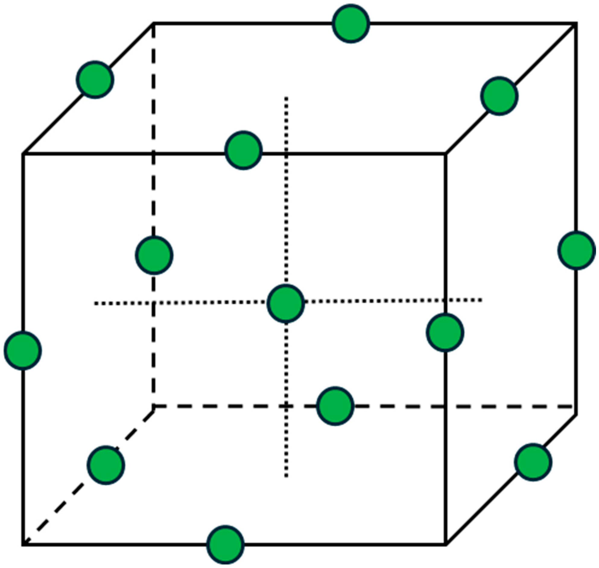
2.1. Box–Behnken Design

Response surface methodology (RSM) is a set of mathematical and statistical techniques employed to model and analyze problems where the desired outcome is influenced by multiple input factors [28]. The primary objective is to optimize the efficiency of the process or reaction. This methodology generates a regression equation (Equation (1)) that accurately characterizes the relationship between the input variables (χ) and the response variable (y). The equation is expressed as follows: y denotes the predicted response, χ signifies the independent variables, β represents the regression coefficients, βii denotes the quadratic coefficients, βij represents the interaction coefficients, and ε accounts for the observed error [29,30].
y = β 0 + i = 1 k β i x i + i = 1 k β i i x i 2 + i j β i j x i x j + ε
This study focuses on determining the impact of input parameters and identifying the optimal values for the CO2 laser cutting of polypropylene. An RSM with the Box–Behnken design (BBD) is used to systematically plan the experiments using Design Expert 12 software (State-Ease, version 12, Minneapolis, MN, USA). The BBD is an RSM used to optimize processes by evaluating the relationships between input parameters and output responses [31,32]. Figure 1 shows the cubic design space constructed by the design matrix derived from the BBD. The experiment was designed by identifying key input parameters; analyzing previous studies to determine the most influential factors; and selecting the laser power (at three levels: 30, 45, and 60 W), cutting speed (at three levels: 30, 45, and 60 mm/s), and focal plane position (at three levels: −3, 0, and +3 mm) as the input parameters. Table 1 presents the details of the independent parameters and the corresponding levels of each parameter. Based on the BBD, the experimental design and corresponding results are listed in Table 2.

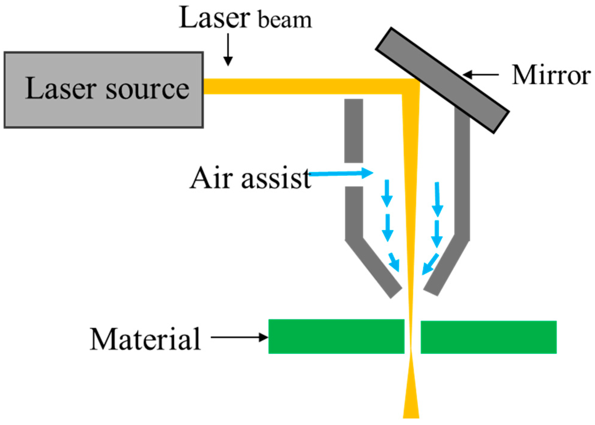
2.2. Experimental Work

This study used a polypropylene sheet with dimensions of 50 cm × 60 cm × 0.7 mm. Polypropylene, a widely utilized thermoplastic material in various industries, presents unique challenges and opportunities in laser cutting processes. Table 3 presents the properties of the PP sheet. The laser cutting experiments were performed using a continuous-wave (CW) CO2 laser cutting machine operating at a wavelength of 1060 nm. The laser beam had a Gaussian profile with a spot size of 0.2 mm at the focal plane. A total of 15 distinct cuts were made, each corresponding to a unique combination of input parameters, as outlined in Table 2. All laser cutting experiments were conducted at a room temperature of 25 ± 1 °C. Figure 2 shows the schematic of the CO2 laser cutting process used in this study.
After the laser cutting process, an optical microscope was employed to measure the kerf width and heat-affected zone (HAZ) to assess the cutting quality. Based on Figure 3, the kerf width and the heat-affected zone (HAZ) of the cutting kerf were measured using ImageJ software (version 1.54p).

3. Results and Discussion

The responses, including kerf width, depth of the cut, and HAZ, were analyzed by generating an ANOVA table. An ANOVA table presents the results of an ANOVA test, in which the probability connected to the F-statistic is known as the p-value.

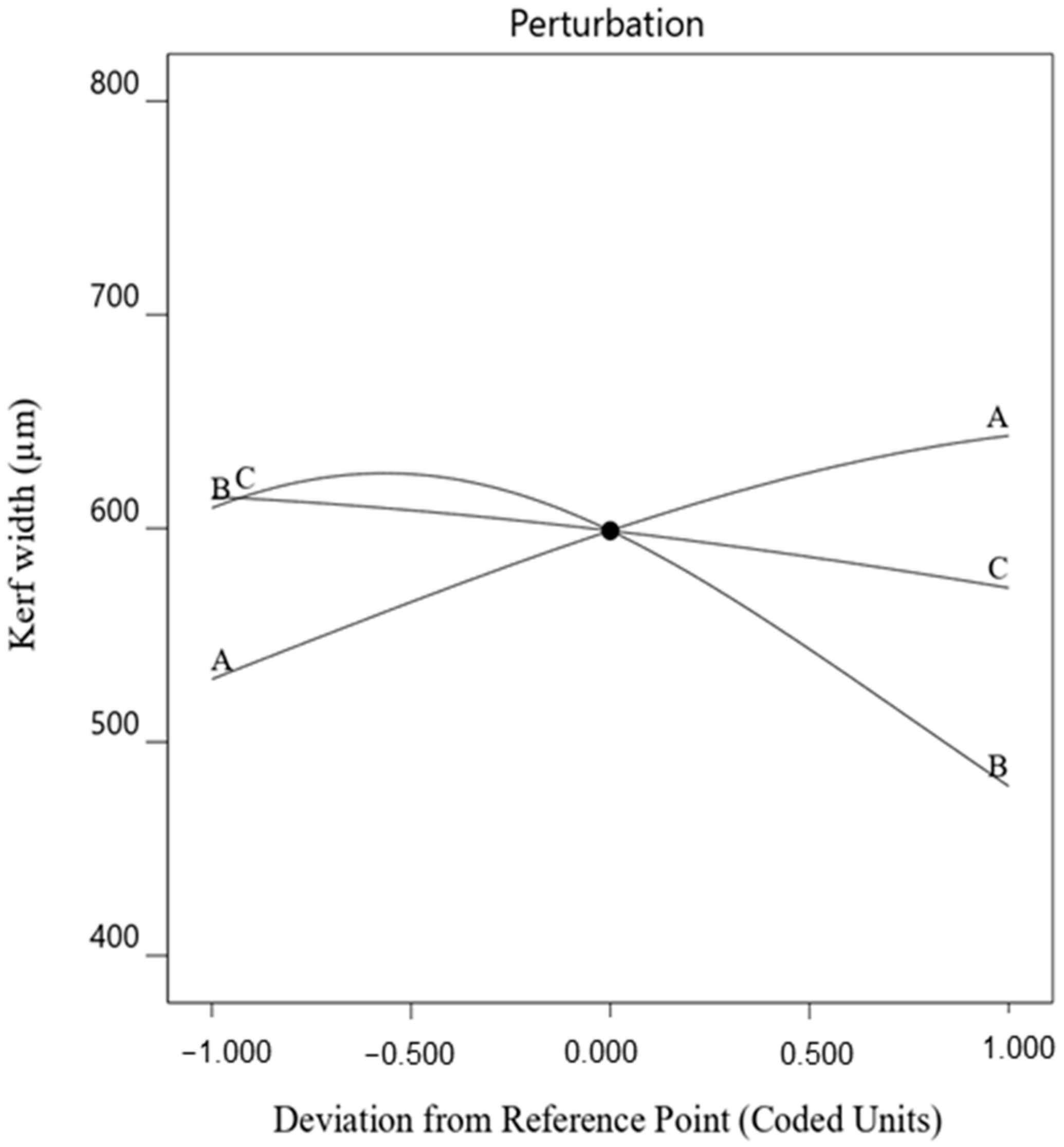
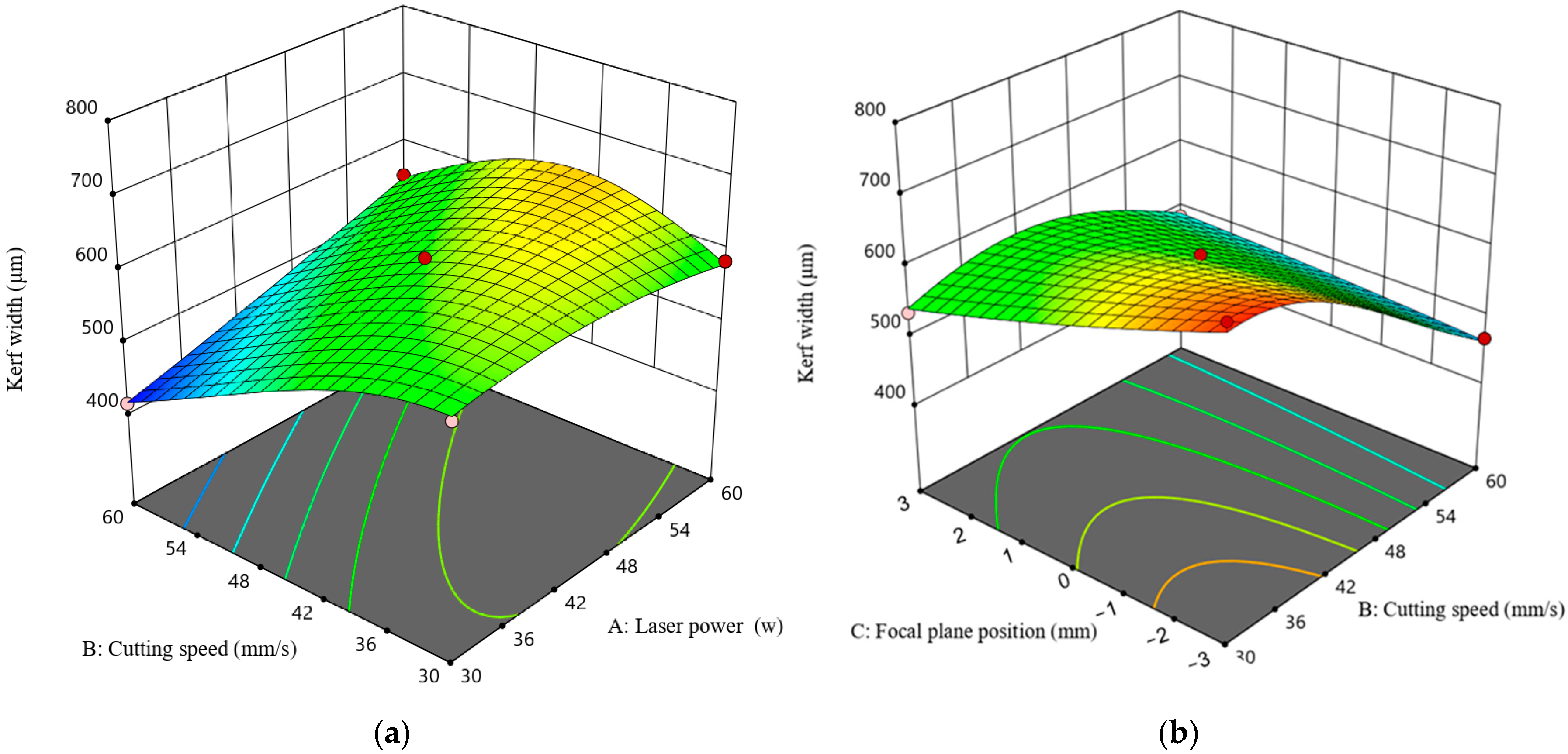
3.1. Analysis of the Width of the Kerf

The kerf width in laser cutting refers to the width of the cut or groove created by the laser beam as it removes material during the cutting process. An analysis of variance (ANOVA) table (Table 4) was generated using Expert 12 software to determine the significant and insignificant parameters affecting kerf width statistically. According to Table 4, the p-values of the main laser cutting parameters—laser power (P), cutting speed (S), and focal plane position (FPP)—along with their interaction terms and the quadratic terms of P (A2) and S (B2), are all less than 0.05. This indicates that these parameters have a significant effect on kerf width. The F-values for P, S, and FPP are 371.40, 179.06, and 22.65, respectively, suggesting that cutting speed has the most significant effect on kerf width, followed by laser power and focal plane position. The final regression equation for the kerf width model is presented in Equation (2) (in terms of actual factors).
K e r f   w i d t h 1.98 = + 5.33999 × 10 6 + 8.58352 × 10 9 × P 8.58352 × 10 9 × S + 9.22082 × 10 7 × F P P 3.1840 × P × S     7.51538 × 10 9 × P × F P P     1.12712 × 10 8 × S × F P P +   1.01751 × 10 9 × P 2 + 3.65871 × 10 9 × S 2 + 7.74143 × 10 9 × F P P 2
Kerf width is a critical parameter for evaluating the performance of the laser cutting process, as it directly affects the quality of the cut. The main effect plot of kerf width (Figure 4) illustrates that the cut width increases with rising laser power and decreasing cutting speed. It has been observed that kerf width is inversely proportional to cutting speed and directly proportional to laser power. An increase in laser power raises the temperature in the cutting zone, generating more molten metal and resulting in a wider kerf, especially at lower cutting speeds. These findings are consistent with the research conducted by Ming [33] and Yilbas [34], who reported that an increase in laser power (P) and a decrease in cutting speed (S) resulted in a wider kerf width. Ultimately, it is evident that within the range of the focal plane position examined in this study, FPP has a negligible effect on the kerf width. In contrast, laser speed and power exhibit a more significant influence.
The surface plot is a three-dimensional graphical representation used to evaluate the response of the kerf width concerning cutting speed, laser power, and focal plane position. In this plot, kerf width is depicted along the z-axis, while cutting speed, laser power, and focal plane position are represented on the x- and y-axes. Figure 5 provides a detailed visualization of how these parameters influence the kerf width. Figure 5a,b show that FPP only slightly affects kerf width, unlike the significant impact of laser power and cutting speed on kerf width. Kerf width can be decreased by minimizing laser power and maximizing cutting speed. According to Figure 5a, the lowest kerf width is observed at 60 mm/s cutting speed and 30 w power.

3.2. Analysis of Heat-Affected Zone (HAZ)

Table 5 presents the ANOVA table for the heat-affected zone (HAZ), generated using response surface methodology (RSM). The ANOVA results show that cutting speed (S, represented by term B) and laser power (P, represented by term A) are significant factors influencing the HAZ in the CO2 laser cutting of polypropylene. The regression equation derived from the primary data analysis is shown in Equation (3).
( h e a t   a f f e c t e d   z o n e ) 2.74 = + 3.98037 × 10 8 + 8.16353 × 10 6 × P 7.78498 × 10 6 × S + 3.09578 × 10 6 × F P P
Figure 6 presents the main effect plot for HAZ, illustrating the impact of laser power, cutting speed, and focal plane position. HAZ increases with decreasing laser power and increasing cutting speed, and increasing the laser power results in a higher energy input, which raises the temperature of the material over a broader region. This extended heat exposure causes the thermal gradient to spread farther from the cut, enlarging the HAZ [35,36]. Simultaneously, decreasing the cutting speed means the laser remains in contact with a given point on the material for longer. This prolonged interaction allows more heat to diffuse into the surrounding areas, further expanding the HAZ [17,36]. The results illustrated in Figure 6 indicate that variations in the FPP exert a negligible influence on the heat-affected zone HAZ.
Figure 7a shows the variation in the HAZ based on the combined impact of S (30 to 60 mm/s) and P (30 to 60 W), while Figure 7b shows the variation in HAZ based on the combined impact of FPP (30 to 60 mm) and P (30 to 60 W). The surface plot reveals that the HAZ reaches its minimum at the highest cutting speed (60 mm/s) and maximum laser power (60 W). Conversely, the maximum HAZ occurs at the lowest cutting speed (30 mm/s) and maximum laser power (60 W).

4. Optimization

In general, various methods and algorithms can be used for numerical optimization [37,38,39], with response surface methodology (RSM) being one of the most widely used techniques for optimization [40]. The main objective of this study is to achieve precise and smooth cutting of polypropylene materials using a CO2 laser cutting machine. To accomplish this, the goal is to minimize the heat-affected zone (HAZ) and kerf width. These objectives serve as the foundation for the optimization process, with detailed information provided in Table 6. Table 6 sets specific goals for each response, with minimum values defined. The targets for optimization are based on these goals. To achieve better quality cuts, each response is assigned equal weight and importance, with a weightage of 1 for each response. The optimal solution is the set of values for the decision variables that yields the best possible outcome according to the objective function while satisfying all constraints. The solution, in terms of actual values, generated using Design Expert 12 software for the response surface design, is presented in Table 7. Figure 8 shows the desirability graph representing the impact of laser cutting and laser power on output responses, predicting the actual responses for kerf width and heat-affected zone (HAZ) at the desired levels of input parameters. The solution obtained from Design Expert 12 software for optimal cutting quality suggests the following values: laser power at 30 watts, cutting speed at 60 mm/s, and focal plane at −3 mm. With this combination, the heat-affected zone (HAZ) will be 1001.314 µm, and the cut width will be 415.721 µm. The desirability of the solution is 0.935.

5. Conclusions

This study investigates the CO2 laser cutting technology for polypropylene materials and aims to optimize input parameters using response surface methodology (RSM) to enhance cut quality, cutting speed, and overall performance. The key findings include the following:
-
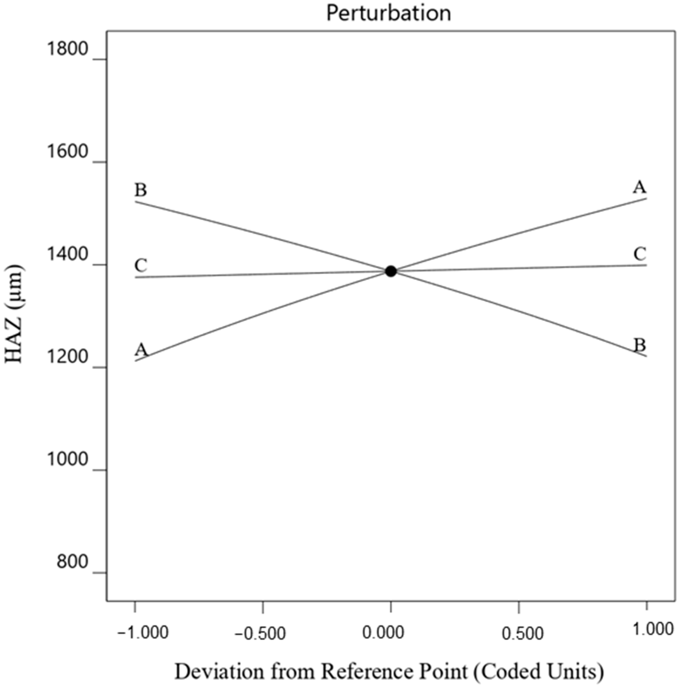
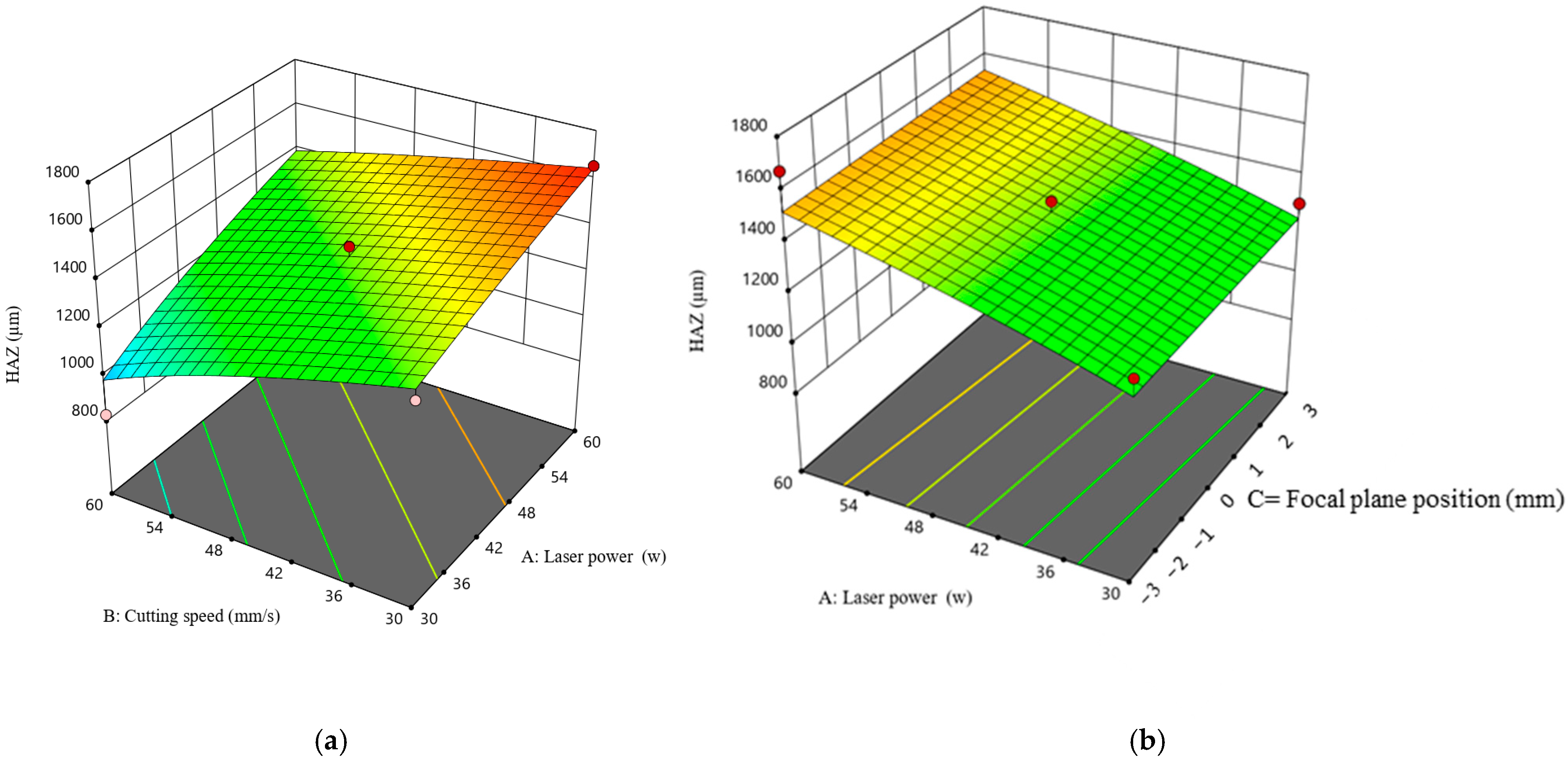
The experiments conducted using the response surface methodology (RSM) show that cutting speed and laser power have a significant influence on both kerf width and HAZ. In contrast, within the range of focal plane position (FPP) examined in this study, FPP exhibits a negligible effect on kerf width and HAZ.
-
The findings show that a decrease in cutting speed and an increase in laser power increase both kerf width and HAZ.
-
The lowest kerf width (414.388 µm) and HAZ (827.338 µm) are observed at a cutting speed of 60 mm/s and a laser power of 30 W.
-
The results indicated that the optimal parameter settings for achieving the minimum kerf width and HAZ are a cutting speed of 60 mm/s, a laser power of 30 W, and a focal plane position of −3 mm.

Author Contributions

Methodology, Z.M.B. and M.M.; Software, O.M.; Validation, F.A.R.; Writing—original draft, O.M. and Z.M.B.; Writing—review and editing, F.A.R. and M.M.; Visualization, O.M., Z.M.B. and M.M.; Supervision, F.A.R. and M.M. All authors contributed equally to this work. All authors have read and agreed to the published version of the manuscript.

Funding

This research received no external funding.

Data Availability Statement

The original contributions presented in this study are included in this article; further inquiries can be directed to the corresponding author.

Conflicts of Interest

The authors declare no conflicts of interest.

References

  1. Chi, Y.; Dong, Z.; Cui, M.; Shan, C.; Xiong, Y.; Zhang, D.; Luo, M. Comparative study on machinability and surface integrity of γ-TiAl alloy in laser assisted milling. J. Mater. Res. Technol. 2024, 33, 3743–3755. [Google Scholar] [CrossRef]
  2. Zhou, Y.; Zhang, Q.; Li, X.; Wang, Y.; Guan, Y. Mechanical performance of laser-textured metallic surface. J. Mater. Res. Technol. 2024, 33, 6084–6089. [Google Scholar] [CrossRef]
  3. Luo, W.; Yuan, X.; Zhang, Z.; Cheng, C.; Liu, H.; Qiu, H.; Cheng, X. Effect of volumetric energy density on the mechanical properties and corrosion resistance of laser-additive-manufactured AlCoCrFeNi2.1 high-entropy alloys. J. Alloys Compd. 2025, 1010, 178032. [Google Scholar] [CrossRef]
  4. Mehrabi, O.; Seyedkashi, S.; Moradi, M. Effect of the Laser Power on the Geometrical Features of 316L Stainless Steel Additively Manufactured by Direct Laser Metal Deposition (DLMD). Lasers Eng. 2023, 56, 127–141. [Google Scholar]
  5. Cui, M.; Shi, G.; Deng, L.; Guo, H.; Xiong, S.; Tan, L.; Yao, C.; Zhang, D.; Deguchi, Y. Microstructure classification of steel samples with different heat-treatment processes based on laser-induced breakdown spectroscopy (LIBS). J. Anal. At. Spectrom. 2024, 39, 1361–1374. [Google Scholar] [CrossRef]
  6. Cui, M.; Shilei, X.; Nan, Y.; Yuanbin, W.; Zhenzhen, W.; Ming, L.; Changfeng, Y. Deguchi Applications of laser-induced breakdown spectroscopy in industrial measurement and monitoring: Multi-technology combination. Appl. Spectrosc. Rev. 2025, 60, 243–291. [Google Scholar] [CrossRef]
  7. Moradi, M.; Mehrabi, O.; Azdast, T.; Benyounis, K.Y. Enhancement of low power CO2 laser cutting process for injection molded polycarbonate. Opt. Laser Technol. 2017, 96, 208–218. [Google Scholar] [CrossRef]
  8. Alsaadawy, M.; Dewidar, M.; Said, A.; Maher, I.; Shehabeldeen, T.A. A comprehensive review of studying the influence of laser cutting parameters on surface and kerf quality of metals. Int. J. Adv. Manuf. Technol. 2024, 130, 1039–1074. [Google Scholar] [CrossRef]
  9. Naresh; Khatak, P. Laser cutting technique: A literature review. Mater. Today Proc. 2022, 56, 2484–2489. [Google Scholar] [CrossRef]
  10. Moradi, M.; Mehrabi, O.; Azdast, T.; Benyounis, K.Y. Effect of the focal plane position on CO2 laser beam cutting of injection molded polycarbonate sheets. Second. Int. Semin. Photonics Opt. Its Appl. 2016, 10150, 56–65. [Google Scholar]
  11. Adin, M.Ş. Investigation of the Effects of Machining Parameters on Kerf Widths during Laser Beam Machining of Medium Carbon Steels. J. Mater. Eng. Perform. 2025, 34, 5304–5315. [Google Scholar] [CrossRef]
  12. Patel, A.; Bhavsar, S.N. Experimental investigation to optimize laser cutting process parameters for difficult to cut die alloy steel using response surface methodology. Mater. Today Proc. 2021, 43, 28–35. [Google Scholar] [CrossRef]
  13. Wang, J.; Sun, Z.; Gu, L.; Azimy, H. Investigating the effect of laser cutting parameters on the cut quality of Inconel 625 using Response Surface Method (RSM). Infrared Phys. Technol. 2021, 118, 103866. [Google Scholar] [CrossRef]
  14. Agarwal, J.; Sahoo, S.; Mohanty, S.; Nayak, S.K. Progress of novel techniques for lightweight automobile applications through innovative eco-friendly composite materials: A review. J. Thermoplast. Compos. Mater. 2020, 33, 978–1013. [Google Scholar] [CrossRef]
  15. Huang, P.; Su, Y.; Luo, H.; Lan, X.; Chong, Y.; Wu, F.; Zheng, W. Facile one-step method to manufacture polypropylene bead foams with outstanding thermal insulation and mechanical properties via supercritical CO2 extrusion foaming. J. CO2 Util. 2022, 64, 102167. [Google Scholar] [CrossRef]
  16. Der, O.; Ordu, M.; Basar, G. Optimization of cutting parameters in manufacturing of polymeric materials for flexible two-phase thermal management systems. Mater. Test. 2024, 66, 1700–1719. [Google Scholar] [CrossRef]
  17. Choudhury, I.A.; Shirley, S. Laser cutting of polymeric materials: An experimental investigation. Opt. Laser Technol. 2010, 42, 503–508. [Google Scholar] [CrossRef]
  18. Deepa, A.; Padmanabhan, K.; Kuppan, P. Analysis and optimization of machining parameters of laser cutting for polypropylene composite. In IOP Conference Series: Materials Science and Engineering, Vellore, India, 2–3 May 2017; IOP Publishing: Bristol, UK, 2017; Volume 263, p. 062043. [Google Scholar] [CrossRef]
  19. Wu, C.; Rong, Y.; Li, M.; Zhang, G.; Huang, Y.; Zhang, T. High-quality cutting of polypropylene (PP) film by UV nanosecond laser based on thermal ablation. Opt. Laser Technol. 2022, 147, 107600. [Google Scholar] [CrossRef]
  20. Singh, Y.; Singh, J.; Sharma, S.; Aggarwal, V.; Pruncu, C.I. Multi-objective Optimization of Kerf-taper and Surface-roughness Quality Characteristics for Cutting-operation On Coir and Carbon Fibre Reinforced Epoxy Hybrid Polymeric Composites During CO2-Pulsed Laser-cutting Using RSM. Lasers Manuf. Mater. Process. 2021, 8, 157–182. [Google Scholar] [CrossRef]
  21. Singh, Y.; Singh, J.; Sharma, S.; Sharma, A.; Chohan, J.S. Process parameter optimization in laser cutting of Coir fiber reinforced Epoxy composite—A review. Mater. Today Proc. 2022, 48, 1021–1027. [Google Scholar] [CrossRef]
  22. Elsheikh, A.H.; Muthuramalingam, T.; Elaziz, M.A.; Ibrahim, A.M.M.; Showaib, E.A. Minimization of fume emissions in laser cutting of polyvinyl chloride sheets using genetic algorithm. Int. J. Environ. Sci. Technol. 2022, 19, 6331–6344. [Google Scholar] [CrossRef]
  23. Sabri, H.; Mehrabi, O.; Khoran, M.; Moradi, M. Leveraging CO2 laser cutting for enhancing fused deposition modeling (FDM) 3D printed PETG parts through postprocessing. Proc. Inst. Mech. Eng. Part E J. Process Mech. Eng. 2024. [Google Scholar] [CrossRef]
  24. Basar, G.; Der, O. Multi-objective optimization of process parameters for laser cutting polyethylene using fuzzy AHP-based MCDM methods. Proc. Inst. Mech. Eng. Part E J. Process Mech. Eng. 2025. [Google Scholar] [CrossRef]
  25. Aydın, K.; Uğur, L. Prediction of Kerf and Groove Widths in CO2 Laser Cutting Process of PMMA Using Experimental and Machine Learning Methods. Exp. Tech. 2025, 1–14. [Google Scholar] [CrossRef]
  26. Kechagias, J.D.; Ninikas, K.; Petousis, M.; Vidakis, N.; Vaxevanidis, N. An investigation of surface quality characteristics of 3D printed PLA plates cut by CO2 laser using experimental design. Mater. Manuf. Process. 2021, 36, 1544–1553. [Google Scholar] [CrossRef]
  27. Kechagias, J.D.; Fountas, N.A.; Ninikas, K.; Petousis, M.; Vidakis, N.; Vaxevanidis, N. Surface characteristics investigation of 3D-printed PET-G plates during CO2 laser cutting. Mater. Manuf. Process. 2022, 37, 1347–1357. [Google Scholar] [CrossRef]
  28. Moradi, M.; Mehrabi, O.; Rasoul, F.A.; Mattie, A.A.; Schaber, F.; Khandan, R. Enhancing 3D Printing Copper-PLA Composite Fabrication via Fused Deposition Modeling through Statistical Process Parameter Study. Micromachines 2024, 15, 1082. [Google Scholar] [CrossRef] [PubMed]
  29. Jensen, W.A. Response Surface Methodology: Process and Product Optimization Using Designed Experiments, 4th ed.; Taylor & Francis, Ed.; Wiley: Hoboken, NJ, USA, 2017. [Google Scholar]
  30. Agha, H.M.; Abdulhameed, A.S.; Jawad, A.H.; Alothman, Z.A.; Wilson, L.D.; Algburi, S. Fabrication of glutaraldehyde crosslinked chitosan/algae biomaterial via hydrothermal process: Statistical optimization and adsorption mechanism for MV 2B dye removal. Biomass Convers. Biorefinery 2025, 15, 1105–1119. [Google Scholar] [CrossRef]
  31. Khan, M.K.A.; Abdulhameed, A.S.; Alshahrani, H.; Algburi, S. Development of chitosan biopolymer by chemically modified orange peel for safranin O dye removal: A sustainable adsorbent and adsorption modeling using RSM-BBD. Int. J. Biol. Macromol. 2024, 261, 129964. [Google Scholar] [CrossRef]
  32. Agha, H.M.; Abdulhameed, A.S.; Jawad, A.H.; Sidik, N.J.; Aazmi, S.; ALOthman, Z.A.; Wilson, L.D.; Algburi, S. Physicochemical fabrication of chitosan and algae with crosslinking glyoxal for cationic dye removal: Insight into optimization, kinetics, isotherms, and adsorption mechanism. Int. J. Biol. Macromol. 2023, 253, 127112. [Google Scholar] [CrossRef]
  33. Li, M. Evaluation of the effect of process parameters on the cut quality in fiber laser cutting of duplex stainless steel using response surface method (RSM). Infrared Phys. Technol. 2021, 118, 103896. [Google Scholar] [CrossRef]
  34. Rajesh, K.; Raju, V.V.M.K.; Rajesh, S.; Varma, N.S.K. Effect of process parameters on machinability characteristics of CO2 laser process used for cutting SS-304 Stainless steels. Mater. Today Proc. 2019, 18, 2065–2072. [Google Scholar] [CrossRef]
  35. Leone, C.; Mingione, E.; Genna, S. Laser cutting of CFRP by Quasi-Continuous Wave (QCW) fibre laser: Effect of process parameters and analysis of the HAZ index. Compos. Part B Eng. 2021, 224, 109146. [Google Scholar] [CrossRef]
  36. Son, S.; Lee, D. The Effect of Laser Parameters on Cutting Metallic Materials. Materials 2020, 13, 4596. [Google Scholar] [CrossRef]
  37. Tao, Z.; Li, W.; Guo, Z.; Chen, Y.; Song, L.; Li, J. Aerothermal optimization of a turbine rotor tip configuration based on free-form deformation approach. Int. J. Heat Fluid Flow 2024, 110, 109644. [Google Scholar] [CrossRef]
  38. Long, X.; Lu, C.; Su, Y.; Dai, Y. Machine learning framework for predicting the low cycle fatigue life of lead-free solders. Eng. Fail. Anal. 2023, 148, 107228. [Google Scholar] [CrossRef]
  39. Peng, X.; Chen, K.; Jia, W.; Li, K.; Huang, C.; Liu, X. Stacking sequence optimization of variable thickness composite laminated plate based on multi-peak stacking sequence table. Compos. Struct. 2025, 356, 118886. [Google Scholar] [CrossRef]
  40. Guo, X.; Tian, D.; Li, C.; Li, X.; Li, W.; Cao, M.; Zhang, F.; Wang, B. Optimization for the Process Parameters of Nickel–Titanium Nitride Composites Fabricated via Jet Pulse Electrodeposition. Nanomaterials 2024, 14, 2034. [Google Scholar] [CrossRef]
Figure 1. Schematic diagram of experimental design of three-parameter Box–Behnken design.
Processes 13 01279 g001
Figure 2. Schematic of laser cutting process.
Processes 13 01279 g002
Figure 3. Schematic of cutting kerf geometry.
Processes 13 01279 g003
Figure 4. Main effect plot for kerf width (A = laser power, B = cutting speed, C = focal plane position).
Processes 13 01279 g004
Figure 5. Three-dimensional surface plot for response kerf width, (a) effect of interaction cutting speed and laser power on kerf width, (b) effect of interaction cutting speed and focal position on kerf width.
Processes 13 01279 g005
Figure 6. Main effect plot for HAZ (A = laser power, B = cutting speed, C = focal plane position).
Processes 13 01279 g006
Figure 7. Three-dimensional surface plot for response HAZ, (a) effect of interaction cutting speed and laser power on HAZ, (b) effect of interaction laser power and focal plane position HAZ.
Processes 13 01279 g007
Figure 8. The desirability graph representing the effect of laser cutting and laser power on output responses, predicting the actual responses for kerf width and heat-affected zone (HAZ) at the desired levels of input parameters.
Processes 13 01279 g008
Table 1. Laser cutting parameters and corresponding levels of each parameter.
Variables NotationUnit−10+1
Laser power Pw304560
Cutting speedSmm/s304560
Focal plane positionFPPmm−303
Table 2. Experimental design and results.
NOInput VariablesOutput Variables
Coded ValuesActual ValuesKerf with (µm)HAZ (µm)
P (W)S (mm/s)FPP (mm)P (W)S (mm/s)FPP (mm)
#1−1−1030300588.51335.3
#2−1013045+3499.31287.8
#31016045+3651.81383.5
#400045450604.31430.2
#50−114530+3535.31517.3
#60−1−14530−3703.61522.3
#70114560+34851509.4
#800045450595.71427.3
#901−14560−3466.91019.4
#1010−16045−3607.91671.9
#11−10−13045−3562.61264.8
#1211060600551.11313.7
#1300045450595.71385.6
#14−11030600414.4827.3
#151−1060300585.61654.7
Table 3. Properties of the PP sheet used in this study [18].
PropertyUniteValue
Densityg/cm30.91
Melting point°C160
Modulus of ElasticityGPa0.9–1.1
Electrical ResistivityΩ/cm1016–1018
Thermal Coefficient ---72–90
Table 4. ANOVA results for kerf width.
SourceSum of SquaresdfMean SquareF-Valuep-Value
Model1.686 × 10−1191.873 × 10−12100.20<0.0001
A—Laser power3.347 × 10−1213.347 × 10−12179.06<0.0001
B—Cutting speed6.942 × 10−1216.942 × 10−12371.40<0.0001
C—Focal plane position4.234 × 10−1314.234 × 10−1322.650.0051
AB2.053 × 10−1212.053 × 10−12109.830.0001
AC4.575 × 10−1314.575 × 10−1324.480.0043
BC1.029 × 10−1211.029 × 10−1255.050.0007
A21.935 × 10−1311.935 × 10−1310.350.0235
B22.502 × 10−1212.502 × 10−12133.87<0.0001
C21.792 × 10−1411.792 × 10−140.95890.3724
Residual9.345 × 10−1451.869 × 10−14
Lack of Fit8.806 × 10−1432.935 × 10−1410.880.0853
Pure Error5.395 × 10−1522.697 × 10−15
Cor Total1.695 × 10−1114
R2 = 0.99Adjusted R2 = 0.98
Table 5. ANOVA results for HAZ.
SourceSum of SquaresdfMean SquareF-Valuep-Value
Model2.297 × 101737.658 × 10167.340.0057
A—Laser power1.200 × 101711.200 × 101711.500.0060
B—Cutting speed1.091 × 101711.091 × 101710.460.0080
C—Focal plane position6.900 × 101416.900 × 10140.06610.8018
Residual1.148 × 1017111.043 × 1016
Lack of Fit1.139 × 101791.266 × 101629.910.0328
Pure Error8.463 × 101424.232 × 1014
Cor Total3.445 × 101714
R2 = 0.66Adjusted R2 = 0.57
Table 6. Optimization criteria.
Parameter/Response GoalLowerUpperImportance
ParameterLaser power In range3060-
Cutting speedIn range3060-
Focal plane positionIn range−3+3-
ResponseCriteria Set 1Kerf widthMinimize414.388703.5973
Heat-Affected ZoneMinimize827.3381671.943
Criteria Set 2Kerf widthMinimize414.388703.5972
Heat-Affected ZoneMinimize827.3381671.945
Criteria Set 3Kerf widthMinimize414.388703.5975
Heat-Affected ZoneMinimize827.3381671.942
Table 7. Optimization result.
SolutionLaser PowerCutting SpeedFocal Plane PositionKerf WidthHAZDesirability
130.00060.000−3.000415.7211001.3140.935
230.00060.000−2.999415.7201001.2940.912
330.00060.000−3.000415.7211001.2930.958
Disclaimer/Publisher’s Note: The statements, opinions and data contained in all publications are solely those of the individual author(s) and contributor(s) and not of MDPI and/or the editor(s). MDPI and/or the editor(s) disclaim responsibility for any injury to people or property resulting from any ideas, methods, instructions or products referred to in the content.

