Article

Pore Structure Characteristics and Controlling Factors of an Interbedded Shale Oil Reservoir—A Case Study of Chang 7 in the HSN Area of the Ordos Basin

1
State Key Laboratory of Petroleum Resources and Prospecting, China University of Petroleum, Beijing 102249, China
2
School of Geosciences, Yangtze University, Wuhan 430100, China
3
College of Geophysics and Petroleum Resources, Yangtze University, Wuhan 430113, China
4
Exploration and Development Research Institute, PetroChina Changqing Oilfield, Xi’an 710018, China
*
Author to whom correspondence should be addressed.
Processes 2025, 13(5), 1331; https://doi.org/10.3390/pr13051331 (registering DOI)
Submission received: 10 April 2025 / Revised: 21 April 2025 / Accepted: 24 April 2025 / Published: 26 April 2025
(This article belongs to the Section Energy Systems)

Abstract

:
The geological structure of interbedded shale oil reservoirs is complex, later characterized by high reservoir heterogeneity and diverse reservoir spaces. These distinctive features are primarily attributed to their unique source–storage configuration. This paper comprehensively investigates the pore structure characteristics and controlling factors, which are beneficial for realizing efficient and sustainable resource utilization. The pore structure characteristics and main control factors of interbedded shale oil in the Heshuinan (HSN) area of the Ordos Basin are studied by analyzing thin sections and scanning them under an electron microscope, and using XRD analysis, a high-pressure mercury injection, a constant-rate mercury injection, and a nitrogen adsorption method. The influence of sedimentation and diagenesis on the pore structure is analyzed. Research shows that the interbedded shale oil reservoirs of the Triassic Chang 7 in the HSN area have an average porosity of 8.47% and an average permeability of 0.74 × 10⁻³ μm2. The reservoirs are classified as typical ultra-low porosity, ultra-low permeability reservoirs. The various pore types in the study area are mainly residual intergranular pores and feldspar dissolution pores. The pores are mostly in the shape of parallel slits and ink-bottle-shaped. The pore-throat radii range from 0.02 μm to 200 μm. Sedimentation and diagenesis jointly control the pore structure in the study area. Sedimentation determines the material foundation of the study area. Diagenesis affects later pore development. Early compaction greatly reduces the intergranular pores, but the chlorite envelope reduces the influence of compaction to some extent. The compacted residual intergranular pores are further reduced by clay minerals, carbonate minerals, and siliceous minerals. Late dissolution promotes pore enlargement, which is the key to the formation of high-quality reservoirs. Furthermore, on this basis, this paper outlines the genetic mechanism of the Chang 7 high-quality reservoir in the HSN area to provide guidance for the exploration and development of interbedded shale oil and gas.

1. Introduction

With the development of the global economy and population growth, the demand for oil resources is increasing. Chang 7 in the HSN area of the Ordos Basin is a high-quality interbedded shale oil reservoir with proven reserves of 20 × 108 t [1,2,3,4,5], which enables strategic support for meeting the needs of the energy provision. Furthermore, the strategic development of mezzanine shale oil presents dual advantages in energy sustainability: its primary significance lies in its capacity to address growing energy demands while simultaneously mitigating the depletion pressures of conventional petroleum resources [6,7,8]. Broadly speaking, interbedded shale oil reservoirs of the Chang 7 reservoir in the HSN area have developed a typical source reservoir interbedded configuration. The interlayering between shale layers in the study area is sandstone, which has a significant impact on the formation, preservation, and later exploitation of shale oil [9,10]. Chang 7 interbedded shale oil reservoir in the HSN area underwent complex diagenesis. Compared to conventional reservoirs, it has lower porosity and permeability [11]. The pores are in the shape of parallel slits and ink bottles. The mechanical properties of rocks are influenced by pore structure, such as Young’s modulus, Poisson’s ratio, etc., and the brittle shale with developed pore structure is more clearly fractured using CO2 fracturing fluid [12,13]. Furthermore, the pore structure control of the physical properties of the reservoir directly restricts the development of the next step [14,15]. Therefore, it is of urgency to characterize the pore structure and identify the controlling factors to guide exploration and development.
Pore structure refers to the spatial distribution, size, shape, and interconnectivity of pores in rocks. The size of the pores determines the porosity, and the distribution, shape, and connectivity determine the permeability. In addition, the porosity and permeability determine the physical properties of the reservoir [16,17]. There are two ways to study pore structures. Firstly, the direct observation method uses a high-resolution scanning electron microscope, X-ray energy spectrum, and CT scanning core to analyze the particle contact relationship, pore size, distribution, and pore shape [18]. Secondly, the indirect measurement method is conducted using low-temperature gas isothermal adsorption, constant-rate mercury injection, high-pressure mercury injection, and numerical simulation, combined with the BET isothermal equation, the Washburn equation, and hysteresis morphology analysis of pore size, shape, and distribution. Previous studies on the Chang 7 reservoir in the Ordos Basin mainly focused on sedimentological and paleoclimatic characteristics, diagenesis, and reservoir space of the reservoir, as well as the oil and gas migration mechanism, and high-quality area distribution [19,20]. The research on the pore structure and master control factors of the Chang 7 reservoir focuses on the pore basin and the Longdong area. However, research on pore structure and main controlling factors of reservoirs with a small study area, with strong heterogeneity, complex source and storage relationship, and strong diagenesis in the study area, is relatively lacking. The pore structure of the Chang 7 interbedded shale oil reservoir in the Ordos Basin is studied through a casting sheet approach, scanning electron microscopy, and mercury pressure experiments. It shows that the Chang 7 reservoir in the Longdong area of the Ordos Basin is mainly controlled by compaction and dissolution, and their effects are roughly the same. In the late stage of diagenesis, this involves filling pores with ferrocalcite and ankerite. The pore structure features of Chang 7 reservoir are influenced by diagenesis. They are also influenced by the sequence of the diagenetic evolution [21]. Strong compaction, weak cementation, and strong dissolution are the key factors for the formation of high-quality reservoirs. The sedimentary sandstone and physical properties of the reservoir in the HSN area are similar to those in the Longdong area and other areas [14], but the oil–water relationship is complex. The pore structure has an obvious control over the distribution of oil and water. At present, the pore structure and main control factors of the Chang 7 interbedded shale oil reservoir are unclear, which restricts the efficient further development of shale oil and gas in the HSN area.
On the basis of detailed core description, this study determines the characteristics and distribution of Chang 7. The pore structure characteristics and main controlling factors of the Chang 7 interbedded shale oil reservoir in the HSN area are clarified by the casting sheet, SEM, XRD analysis, CT scan, high-pressure mercury, constant-speed pressure mercury, nitrogen adsorption, etc.

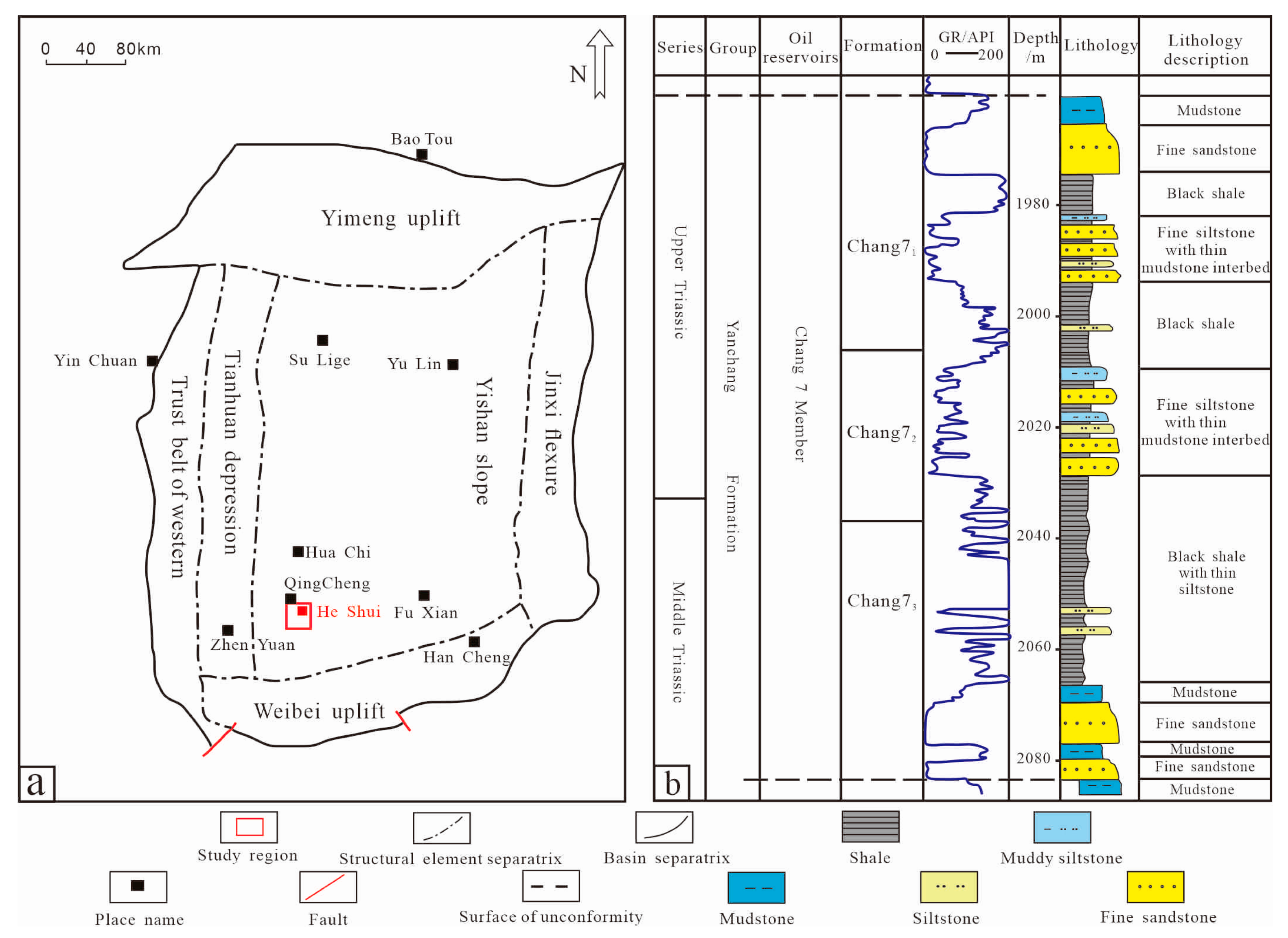
2. Geological Background

The Ordos Basin is the second largest continental sedimentary lake basin in China, located in central and western China, spanning five provinces: Gansu, Shaanxi, Inner Mongolia, Shanxi, and Ningxia, with a total area of 37 × 104 km2 [22,23]. It developed a river-dominated delta–lacustrine sedimentary system. The Triassic Yanchang Formation of deposition is the focus of shale oil and gas exploration and development, among which the Chang 7 section is one of the key target layers. The Yanchang Formation was deposited in 10 strata from bottom to top, comprising 10 well-developed sections; the Chang 7 deposits reached a peak and the sedimentation of the Yanchang Formation concluded at the end of the Triassic [24,25].
The study area is located in Heshui County, Qingyang City, Gansu Province, in the southwest region of the Yishan slope (Figure 1a). The target layer is Chang 7 segments, whose main sedimentary stage is the formation and transformation of sandy debris flow and turbidity current sand bodies. Formed in a semi-deep to deep lake sedimentary environment, a deep-water gravity flow sedimentary system triggered gravity collapse, providing terrestrial debris. According to the sedimentary characteristics and the sequence stratigraphy method, Chang 7 is divided into three sublayers, respectively, Chang 71, Chang 72, and Chang 73. The Chang 7 section of the HSN area was deposited in a semi-deep to deep lake sedimentary environment. The sandy debris flow, turbidity current, and deep lake mudstone deposition are present. Two sub-layers, Chang 71 and Chang 72, mainly consist of gray and gray–black sand debris flow and turbidity current, which are the high-quality reservoirs in the study area. Chang 73 small layers developed a set of high-quality hydrocarbon source rocks, mainly black deep lake mudstone with thin siltstone interbeds. Two sets of high-quality reservoirs of Chang 71 and Chang 72 are directly superimposed on the source rock of Chang 73, forming a good source–storage relationship [26] (Figure 1b).
The grain of the rock is a fine-grained Chang 7 interbedded shale oil reservoir in the HSN area. The most developed aspects are fine sandstone, siltstone, pelitic siltstone, and silty mudstone. The major rock types are feldspathic litharenite and lithic arkose. The main mineral components are quartz and feldspar. The filling material is mainly composed of clay minerals. The cement is composed of iron-bearing calcite cement and iron-bearing dolomite cement. Overall, the quartz content is relatively low, which presents low component maturity; the illite and chlorite have relatively high contents [21,22].

3. Experiments and Methods

3.1. Samples

The study samples were obtained from the Triassic Series. A total of 10 samples were collected for petrographic observation, XRD analysis, CT scan, high-pressure mercury injection (HPMI), rate-constant speed pressure mercury injection (RCMI), and low-temperature nitrogen adsorption (LTNA).

3.2. Petrographic Observation

In total, 40 thin sections were observed petrographically; 10 of them were from collected core samples, and the remaining 30 were from the China National Petroleum Corporation (CNPC) Exploration and Development Research Institute of Changqing Oilfield. Polarized microscope (PM) and scanning electron microscope (SEM) observations, combined with X-ray diffraction (XRD) and computer tomography (CT) scans, were used to analyze the reservoir mineral type, particle size, contact relationship, pore type and morphology, and pore and throat connectivity characteristics. The microscopic photos and XRD and CT analysis data were obtained from the Experimental Center of Daqing Exploration and Development Research Institute in Heilongjiang Province.

3.3. Experimental Measurement

LTNA experiments were carried out on 10 collected samples. According to the nitrogen adsorption volume and relative pressure in the process of nitrogen adsorption and desorption, the pore morphology was analyzed through hysteresis characterization. HPMI technology was used to identify the pore structure and pore size distribution of 10 samples, following the testing standards GB/T29172-2012 [27] Core Analysis Method and GB/T29171-2012 Determination of Rock Capillary Pressure Curve. The test used corelab CMS300 (Core Laboratories, Holland, Amsterdam) and an AutoPore IV 9500 (Micromeritics, Norcross, GA, USA) mercury press with a maximum experimental pressure of about 200 MPa. Mercury does not wet the rock surface. When the injection pressure is higher than the capillary pressure corresponding to the pore throat, mercury enters the pores. At this stage, the injection pressure is equivalent to the capillary pressure, and the corresponding capillary radius is the pore-throat radius (Table 1).
We calculate the pore radius according to the Washburn formula (Equation (1)):
Pc = 2 σ c o s θ r
In this equation, Pc—capillary pressure, MPa; σ—interface tension to air, σ = 480 dyn/cm; θ—wetting angle of mercury to rock, θ = 140, cos θ = 0.765; r—pore radius, μm.
The pore and throat size distribution of four samples were analyzed by RCMI. Tests were conducted following GB/T29172-2012 and using the ASPE-730 (Cordx Union, Atlanta, GA, USA) constant speed pressure mercury instrument with constant mercury intake speed (0.00005 mL/min). At a very low constant velocity, the process of the capillary pressure process within the system can be observed. Operating at a low constant speed, the mercury intake process can be approximated as a quasi-static process. In that case, according to the natural pressure fluctuations that occur when passing through different microscopic pore shapes the microstructure of the pores can be determined. The technical feature is the ability to distinguish the throat from the pore. It can measure the pore radius distribution and the throat radius distribution separately (Table 2).

4. Results

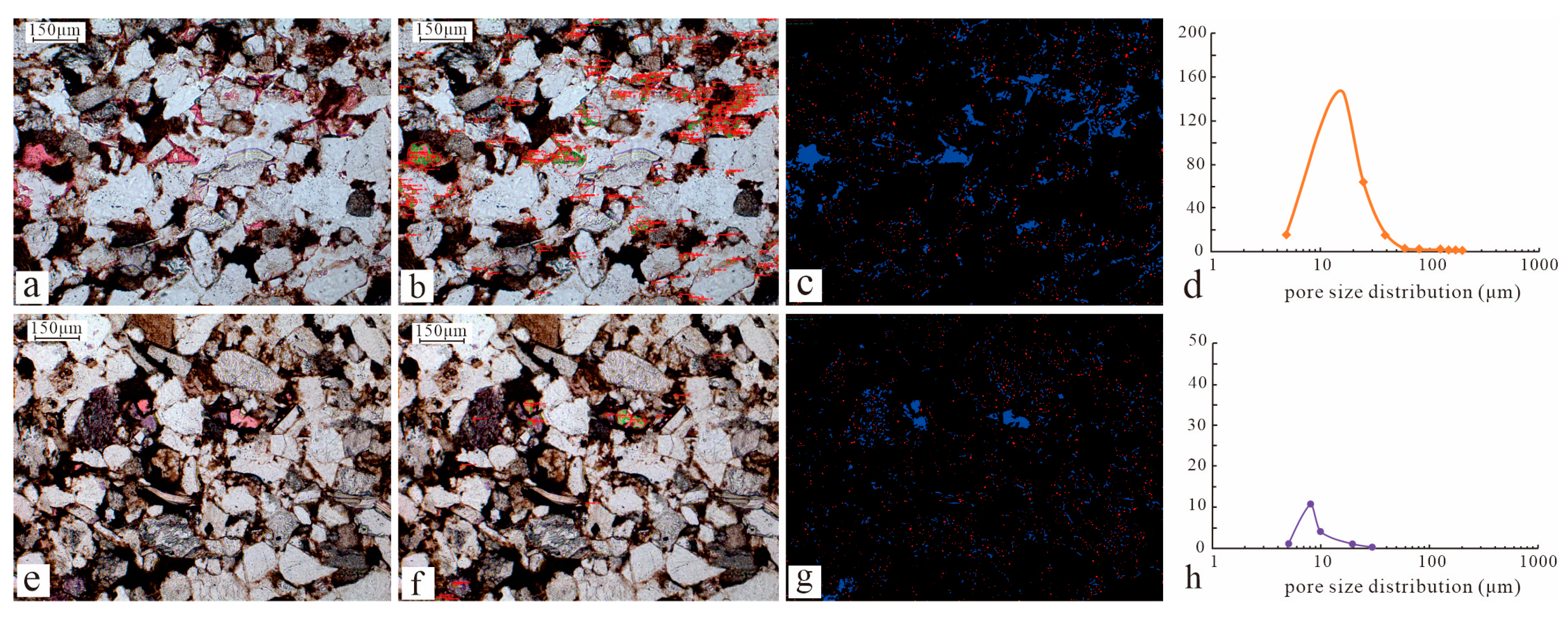
4.1. Pore Type and Pore Shape

Various types of pores develop in the Chang 7 reservoir of the HSN area, and under microscopy, we can see a large number of residual intergranular pores, dissolution pores, and intercrystalline pores, and a small number of microcracks. The residual intergranular pores are formed mainly through compaction and cementation, and the dissolution pores are mainly formed from feldspar and debris dissolution. The study area experienced strong cementation, and the compaction-reduced intergranular pores are relatively less retained. Microscopy reveals a clear boundary without cement between particles (Figure 2a). Most of them are cemented residual intergranular pores, and the residual pores of authigenic quartz mineral cemented pores can be seen under the microscope (Figure 2b). The dissolution direction of the feldspar dissolution pore is mostly along the cleavage. The rock debris dissolution pores are formed by the dissolution of debris with high concentration of soluble components, with irregular pore distribution. When the particles are completely dissolved, the mold pores are formed (Figure 2c–e). Intercrystalline pores mainly refer to the intercrystalline pores of clay minerals. Accordion-shaped interstitial pores of kaolinite, and bridging-shaped and honeycomb-shaped interstitial pores of illite can be seen from SEM and PM (Figure 2f–h), with certain levels of connectivity. A small number of developed microfractures are mainly due to uneven tectonic activity (Figure 2i).
The temperature is 77.3 K (liquid nitrogen temperature) and the relative pressure is 0.010~0.095 MPa in the LTNA experiment. Nitrogen was used as the adsorption medium to determine the nitrogen adsorption amount of the sample. From this, the nitrogen can be obtained using the nitrogen adsorption–desorption isotherm of the sample. In the process of nitrogen adsorption and desorption the hysteresis occurs, and, according to the morphology of the hysteresis, we can effectively judge the pore shape [28]. According to the IUPAC classification of hysteresis [29], most of the hysteresis types in the study area belong to the H3–H4 compound, a small amount of the H2–H3 transition type. The hysteresis is narrow and the N2 adsorption amount is small, indicating that the pore shape is mainly parallel slits and ink-bottle-type pores, which is consistent with that observed under SEM (Figure 3).

4.2. Pore Structure and Pore Radius

The distribution characteristics of the pore throat in the interbedded shale oil reservoir in the HSN area were studied using HPMI. According to the morphology of the mercury pressure curve, the development characteristics of the pore throat can be judged. Moving along the direction of the arrow shows a gradual decrease in the discharge pressure and increasing maximum mercury saturation, indicating that the structure of the rock pore is improving (Figure 4a). The experimental results show that the maximum mercury saturation of the interbedded shale oil reservoir in the HSN area is 34.12–93.26%, with an average of 80.9%; the displacement pressure is 0.57–26.37 MPa, with an average of 3.09 MPa; and the mercury withdrawal efficiency is mostly lower than 40% (Figure 4b,c). High-pressure mercury experiments show that the pore structure fundamentally controls the physical properties of the interbedded shale oil reservoir. The greater the displacement pressure, the smaller the reservoir permeability. The greater the maximum mercury saturation, the greater the reservoir porosity and permeability (Figure 4d,e).
CT can more intuitively show the microscopic heterogeneous characteristics of interbedded shale oil reservoirs. The CT results of the samples show that the Chang 7 interbedded shale oil reservoir had strong heterogeneity, with uneven distribution of pores at all scales, and with pores developed from dozens of microns to nanometer scale. The more single the color (red, yellow), the larger the pores and the better the physical property (Figure 5). According to CT, the number of holes and pores, average pores, and throat radius of the N143 well are larger than those of the LY18 well. Rock samples from N143 have a porosity of 9.9% and a permeability of 0.1 mD, while samples from LY18 show 7.1% porosity and 0.04 mD permeability, according to HPMI data (Table 3). The pore structure and physical properties of the N143 well are significantly better than those of the LY18 well, indicating that the physical property of the reservoir is directly controlled by pore-throat size and connectivity.
HPMI can measure a wide range of pore radius distribution, but it is not accurate enough for non-circular pore measurements, and cannot distinguish between pore and throat. RCMI can accurately measure non-circular pores, and can effectively distinguish the pores and throat, but the measured pore radius range is limited [30,31]. Therefore, we combine HPMI and RCMI experiments to obtain the full pore size distribution characteristics of the interbedded shale oil reservoir. The throat radius of the reservoir pore is mainly 0.02–200 μm, the pore radius is mainly 30–200 μm, and the throat radius is mainly 0.3–2 μm. Along the direction of the arrow, the throat radius gradually decreases, and the permeability also decreases along this direction. This indicates that the permeability of the rock is determined by the throat radius; the larger the throat, the better the reservoir property (Figure 6).

5. Discussion

5.1. Control of Pore Structure by Sedimentation

On the basis of previous studies, according to the classification of typical and atypical gravity flows proposed by Bauma and Walker, we provide a detailed observation of the Chang 7 core in the HSN area. It is believed that the Chang 7 reservoir in the HSN area is the result of deep-water gravity flow. The sediments mainly consist of sand debris flows and turbidity currents. The sand debris flow deposits have fine particle sizes, good sorting and rounding, low matrix content, and good physical properties. The mainly developed massive oily fine sandstone and parallel bedding and irregular mud debris can be seen in the sandstone (Figure 7a–c). The deposition of the turbidity current is very fine-grained, with a high matrix content and poor physical properties. It is a non-Newtonian fluid. It mainly contains muddy siltstone or silty mudstone, showing the Bouma sequence sections B and C, flame structures, and groove cast in the core (Figure 7d–f).
The sedimentary environment and material basis of the reservoir control the pore structure. Under the background of gravity flow deposition, the sediment underwent rapid accumulation and the particle arrangement was non-directional, causing less pore formation between particles. The target layer was deposited in the semi-deep lake–deep lake deposition environment where the deposited water was deep and the sediment was far from the source. After long distance transport, the sediment had fine grain size, good sorting, high mud content, and small reservoir original pores. Sandy debris flow develops in a high-energy sedimentary environment, and turbidity current deposition develops in a relatively low-energy sedimentary environment. Compared with the turbidity current deposition, the sandy debris flow has larger grain size, mainly fine sandstone, and pores are relatively developed (Figure 8a). Under the PM, the pore development of sand debris flow is better than that of the turbid current. The average particle size and face rate show significant positive correlation, confirming the influence of deposition environment on the pore (Figure 8b). The sediment size and matrix content determine the original porosity and permeability of the reservoir. The sandy debris flow has large sediment size, less matrix, and high original porosity and permeability. The turbidity current sediment has small grain size, high matrix, and low original porosity and permeability. The statistical results confirm that the porosity and permeability of sand debris flow deposits are significantly better than those of the turbidity current deposits (Figure 8c,d).

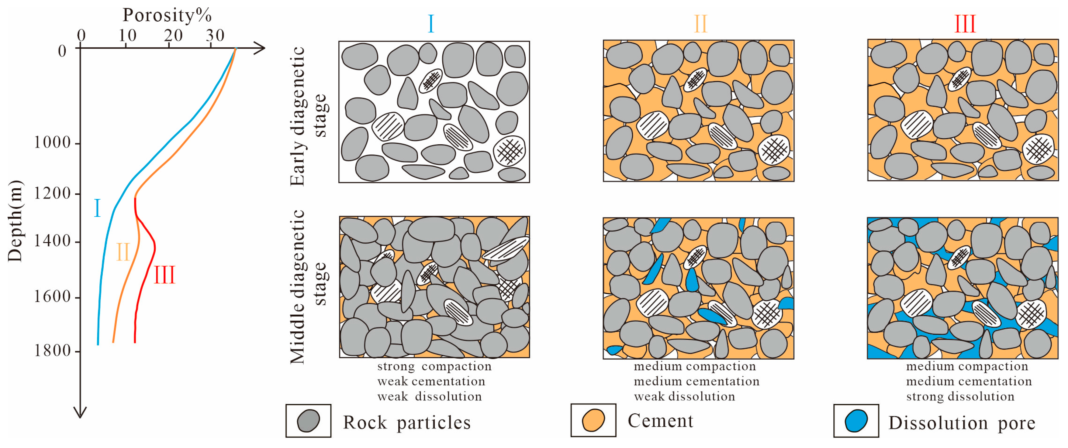
5.2. Control of Pore Structure by Diagenesis

5.2.1. Diagenesis

Compaction

Under the background of gravity flow deposition, the deposit of the sediment has fine sizes, high matrix content, fast deposition, and poor rock compressional strength, which leads to strong compaction during later diagenesis. The compaction strength of the reservoir increases with burial depth. The interparticle contact relationship changes from the original point-line contact to line contact, and further progresses to concave–convex contact or even suture-like contact (Figure 9a). Under PM and SEM observation, plastic particles such as mica and clay debris can be deformed under compression and be rearranged (Figure 9b). Rigid particles such as quartz and feldspar can be fractured (Figure 9c).

Cementation

Various types of interbedded shale oil reservoirs are developed in the HSN area. Based on XRD analysis in the study area, clay minerals are predominant, followed by carbonate cement. Affected by the strong compaction, the reservoir pores are greatly reduced, with pore types mainly consisting of small pore throats. Fluids in small pore throats are prone to semi-permeable membrane effects, causing strong carbonate cementation and clay cementation and resulting in the reservoir suffering from strong cementation. Cementation, through a series of physicochemical interactions, fills intergranular pores and accompanies various stages of the diagenesis period. This is another important factor leading to pore reduction in the reservoir.
(1)
Carbonate cementation
The carbonate cementation was dominated by late ferrocalcite and ankerite, which were widely distributed in the study area with an average volume fraction of 4.3%. Multi-stage carbonate cementation can be seen under the PM and SEM. Early carbonate cements are mostly without iron minerals, with poor crystallization and small crystal particle size. Self-shaped rhomboid dolomite fills the pores (Figure 9d). Late carbonate cements are mostly iron minerals, with good crystallinity and large crystal particle size. Under the PM, dark red ferrocalcite and light blue ankerite stained with potassium ferrocyanide and alizarin red can be observed. This filling of pores by porosity type cementation is shown (Figure 9e).
(2)
Clay cementation
The average volume fraction of self-generated clay minerals in the Chang 7 interbedded shale oil reservoir in the HSN region is 5.7%. Under the PM and SEM, we can see illite, chlorite, kaolinite, montmorillonite, and an illite/smectite mixed layer, mainly illite and chlorite, and other clay minerals are relatively less developed. There are bridging-shaped and honeycomb-shaped interstitial pores of illite (Figure 2f,g). They mainly originate from the montmorillonite formed during early diagenesis and are widely distributed on the surfaces of feldspar, debris, and other particles. The clay cement in the study area is mainly illite, with an average mass fraction of 39.8%, which greatly reduces the compaction residue intergranular pores of the reservoir. Chlorite occupies a relatively low proportion of clay cement, averaging 21.5%, and exhibits filamentous morphology under the microscope (Figure 9f). Chlorite is present in the pore mainly in two forms. When the chlorite content is low, chlorite mainly attaches to the surface of particles. On the one hand, it can reinforce the pores to increase the compaction resistance of the pores. On the other hand, it can effectively inhibit the secondary increase in mineral particles, which is conducive to the preservation of the pores. When the content of chlorite is high, a small amount of the chlorite attaches to the surface of particles, while the rest directly fills the pores, which is not conducive to pore preservation. The chlorite is relatively developed in the study area, which can increase the anti-compaction ability of the reservoir, inhibit the secondary growth of minerals, and be conducive to the preservation of the reservoir pores.

Dissolution

The reservoir is subjected to strong compaction and strong cementation, resulting in a highly tight reservoir. The intensity of the dissolution effect is the key to the formation of high-quality reservoirs. Microscopic observation showed that the dissolved pores in the study area are mainly feldspar and rock debris dissolution pores (Figure 2c–e). The dissolved pore radius was extracted, and we calculated the areal percentage of the cast thin section using the convex hull method [32,33]. The blue region shows the extracted dissolved pores, and the red region represents the extracted primary pores (Figure 10c,g). The dissolution degree of different samples varied significantly (Figure 10d,h). In the core sample from well N11 at 1141 m depth, dissolution pores are relatively numerous, with a total areal percentage of 6.03%, of which dissolved pores account for 5.31%. In contrast, the core sample from well N11 at 1147 m contains fewer dissolution pores, showing a total areal percentage of 2.83%, with dissolved pores accounting for 2.1% (Figure 10c,g).
In the process of diagenesis evolution, the dissolution of potassium feldspar will produce a large number of potassium ions. Potassium ions can effectively promote montmorillonite illitization. However, a large number of sodium ions will be produced in the process of illitization to form a dissolution barrier on the surface of the plagioclase to inhibit plagioclase dissolution. The widely developed illite cement in the study area indicates the presence of potassium feldspar massive dissolution. XRD analysis showed that the average content of plagioclase in the reservoir was three times that of potassium feldspar, confirming that the dissolution pores mainly originate from the potassium feldspar.

5.3. Advantageous Reservoir Forming Mechanism

The diagenetic evolutionary sequence of interbedded shale oil reservoirs is compaction → quartz increasing → chlorite, illite, calcite cementation → feldspar, debris, and calcite dissolution → ferrocalcite, ankerite cementation [14]. According to the different formation processes of sand bodies, the reservoirs can be classified into three types:
Type I reservoir: Strong compaction leading. This kind of reservoir is mostly turbidite current with high plastic debris content and low rigid mineral content. These reservoirs have undergone strong compaction, strong cementation, and weak dissolution (Figure 11(I)). The reservoir porosity < 5%, and permeability < 0.05 mD, with very small pore radial distribution around 10 nm, and maximum mercury saturation < 30%. Dissolution features are poorly developed (Figure 4a Z306 well rock sample).
Type II reservoir: Medium compaction, medium cementation leading. This kind of reservoir has increased rigid particles, and anti-compaction ability is enhanced. It also suffers weak dissolution (Figure 11(II)). The reservoir porosity is 5~8%, permeability is 0.05~0.1 mD, the pore radius is small, averaging around 50 nm, the maximum mercury saturation is 30~70%, and both cementation and dissolution are relatively well developed (Figure 4a N23 well rock sample).
Type III reservoir: Medium compaction, medium cementation, medium dissolution leading. This kind of reservoir is mostly composed of sandy debris flows, with strong compaction resistance, large pores, and many soluble substances such as feldspar and debris (Figure 11(III)). Well-developed dissolved pores can be observed under the PM. The reservoir porosity > 8%, permeability > 0.1 mD, with pore radius distributed around 1 μm, maximum mercury injection saturation > 70%, and strong dissolution development (Figure 4a N143 well rock sample).

6. Conclusions

(1)
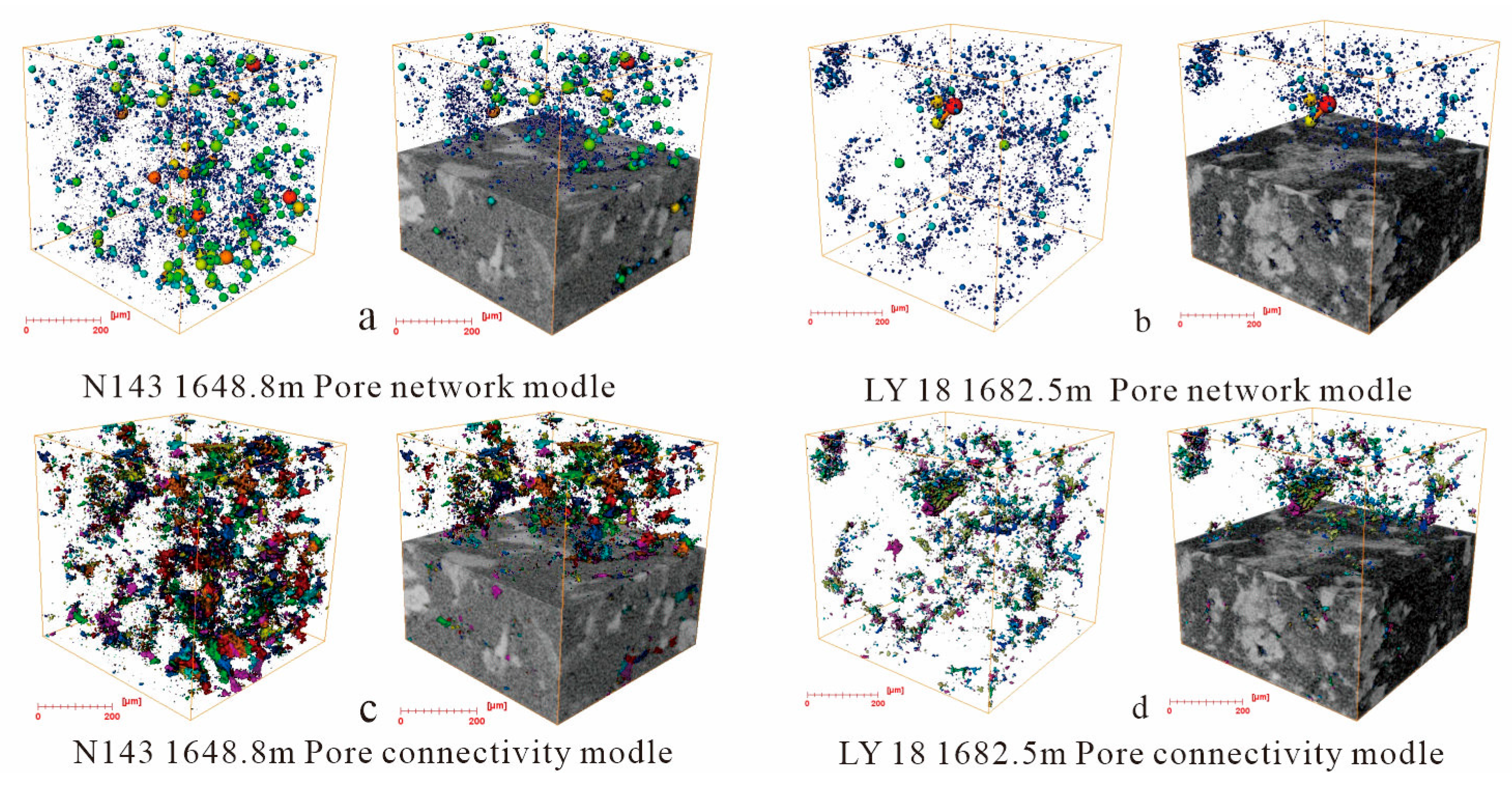
The Chang 7 interbedded shale oil reservoir in the HSN area has extremely strong heterogeneity and extremely low porosity and permeability. The pore types are diverse, mainly feldspar and debris dissolution pores, residual intergranular pores, and a small number of microcracks are developed.
(2)
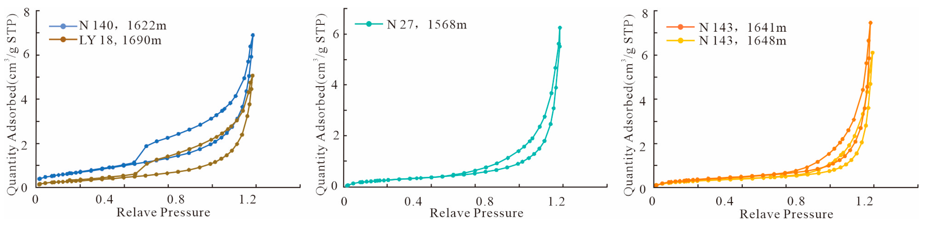
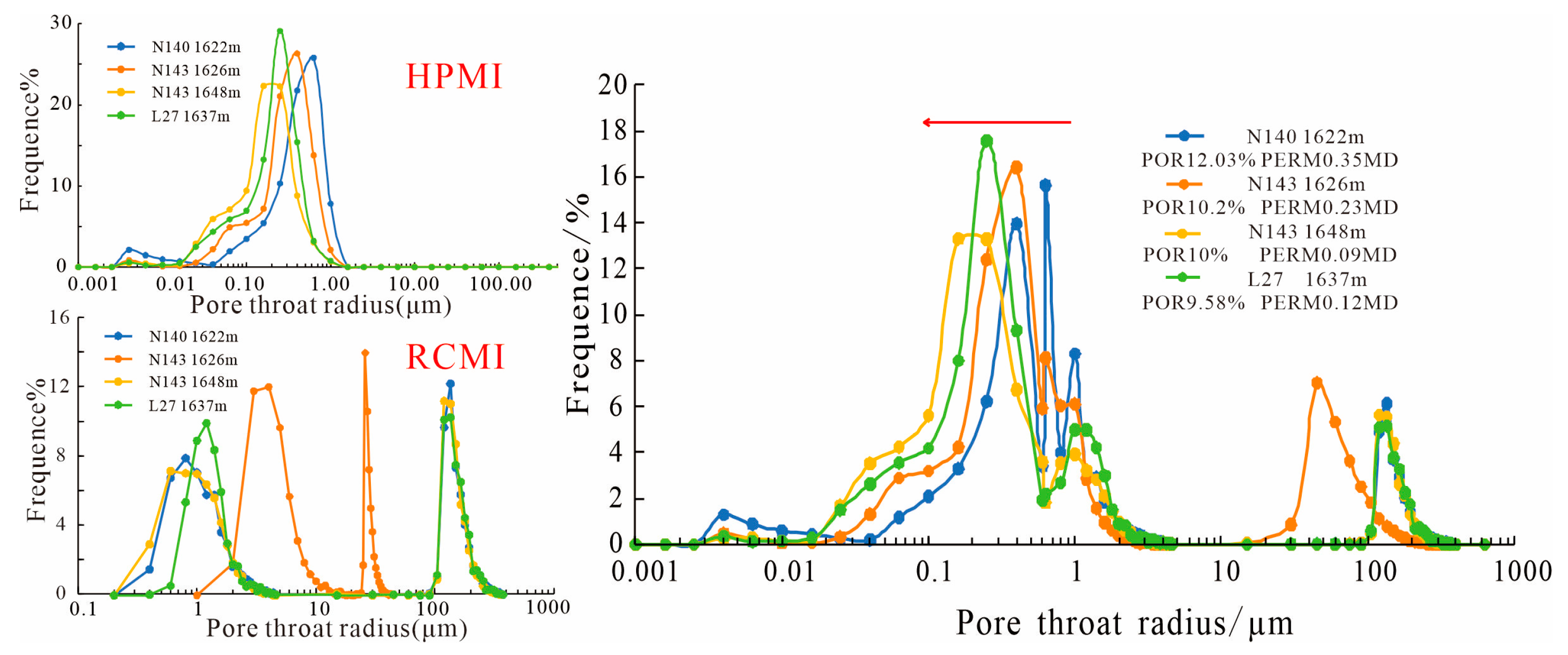
The pore shapes are mainly parallel-slit and ink-bottle shapes. The pore radius is mainly distributed in the range of 30 to 200 µm, and the throat radius is mainly distributed in the range of 0.3 to 2 µm.
(3)
The pore structure of interbedded shale oil reservoirs in the HSN area is controlled by sedimentation and diagenesis. Sedimentation determines the material basis of fine size and high matrix clay content. Compaction and cementation are the main factors for reducing pores in the study area. The effect of sand debris flow is reduced by cementation. The effect of turbidity current is reduced by compaction. The strength of dissolution is the key to the development of high-quality reservoirs.
(4)
We established the formation mode of the high-quality reservoir of the Chang 7 interbedded shale in the HSN area. The formation of the sandy debris flow is attributed to medium compaction, medium cementation, and medium dissolution, which results in good physical properties and large pore sizes. It is the main factor for high-quality reservoirs in the study area.

Author Contributions

Conceptualization, L.F. and B.Z.; methodology, L.F.; validation, L.F., X.W., and S.M.; formal analysis, X.W.; investigation, L.F.; resources, X.W.; data curation, L.F.; writing—original draft preparation, L.F.; writing—review and editing, L.F., B.Z., and S.M.; visualization, B.Z.; supervision, S.M.; project administration, S.M.; funding acquisition, B.Z. All authors have read and agreed to the published version of the manuscript.

Funding

This study was supported by State Key Laboratory of Petroleum Resources and Prospecting, China University of Petroleum and Exploration PRP/open-2206.

Data Availability Statement

The data in this paper come from the research project concerning the evaluation of interbedded shale oil reservoir quality in the HSN area of Ordos Basin. This is real and effective.

Acknowledgments

The authors thank the reviewers for their patient work.

Conflicts of Interest

The author Shuwei Ma is employed by Exploration and Development Research Institute, PetroChina Changqing Oilfield. The remaining authors declare that this research was conducted in the absence of any commercial or financial relationships that could be construed as potential conflicts of interest.

References

  1. Zhang, W.X. Development and prospect of oil and gas resource evaluation. Fault-Block Oil Gas Field 1994, 38–40+49. [Google Scholar]
  2. Zou, C.; Pan, S.; Jing, Z.; Gao, J.; Yang, Z.; Wu, S.; Zhao, Q. Shale oil and gas revolution and its impact. Acta Pet. Sin. 2020, 41, 1–12. [Google Scholar]
  3. Wang, X.; Hou, J.; Li, S.; Dou, L.; Song, S.; Kang, Q.; Wang, D. Insight into the nanoscale pore structure of organic-rich shales in the Bakken Formation, USA. J. Pet. Sci. Eng. 2020, 191, 107182. [Google Scholar] [CrossRef]
  4. Li, G.X.; Zhu, R.K. Progress, challenges and key issues of uncoventional oil and gas development of CNPC. China Pet. Explor. 2020, 25, 1–13. [Google Scholar]
  5. Tanguang, F.; Xiongfei, X.; Liang, F.; Yaqin, F.; Wenhui, L.; Juntian, L.; Meiyan, W.; Guoqiang, J. Geological characteristics and exploration prospect of shale oil in Permian Lucaogou Formation, Santanghu Basin. China Pet. Explor. 2021, 26, 125–136. [Google Scholar]
  6. Yang, H.; Li, S.X.; Liu, X.Y. Characteristics and resource prospects of tight oil and shale oil in Ordos Basin. Acta Pet. Sin. 2013, 34, 1–11. [Google Scholar]
  7. Ma, W.Z.; Wang, Y.H.; Zhang, S.; Fe, S.B.; Ha, B.Y.; Cu, X.L. Microscopic characteristics and controlling factors of Chang 7 Member shale oil reservoir in northern Shanxi area, Ordos Basin. Nat. Gas Geosci. 2021, 32, 1810–1821. [Google Scholar]
  8. Wang, Z.; Li, Z.; Xi, K.; Wu, Y. Analysis of main control factor of Mesozoic oil and gas accumulation in Ordos Basin of Zhenjing rejion. Fault-Block Oil Gas Field 2007, 14, 25–27+90. [Google Scholar]
  9. Fu, J.H.; Yu, J.; Xu, L.M.; Niu, X.B.; Feng, S.B.; Wang, X.J.; You, Y.; Li, T. New Progress in Exploration and Development of Tight Oil in Ordos Basin and Main Controlling Factors of Large-scale Enrichment and Exploitable Capacity. China Pet. Explor. 2015, 20, 9–19. [Google Scholar]
  10. Li, W.; Wen, Z.G. Characterisitics and distribution of Chang7 source rocks of Yangchang Formation in Maling Area of Ordos Basin. Fault-Block Oil Gas Field 2014, 21, 24–27. [Google Scholar]
  11. Zhao, W.Z.; Hu, S.Y.; Hou, L.H. Connotation and strategic role of in-situ conversion processing of shale oil underground in the onshore China. Pet. Explor. Dev. 2018, 45, 537–545. [Google Scholar] [CrossRef]
  12. Li, Q.; Li, Q.C.; Cao, H.; Wu, J.; Wang, F.; Wang, Y. The Crack Propagation Behaviour of CO2 Fracturing Fluid in Unconventional Low Permeability Reservoirs: Factor Analysis and Mechanism Revelation. Processes 2025, 13, 159. [Google Scholar] [CrossRef]
  13. Li, Q.C.; Li, Q.; Wu, J.; Li, X.; Li, H.; Cheng, Y. Wellhead Stability During Development Process of Hydrate Reservoir in the Northern South China Sea: Evolution and Mechanism. Processes 2025, 13, 40. [Google Scholar] [CrossRef]
  14. Wang, X.; Yu, S.; Li, S.; Zhang, N. Two parameter optimization methods of multi-point geostatistics. J. Pet. Sci. Eng. 2022, 208, 109724. [Google Scholar] [CrossRef]
  15. Tang, H.P.; Chen, S.J.; Zhang, X.W.; Huang, Y.L.; Yao, Y.T. Influence of physical property and pore throat structure on oiliness of tight sandatone reservoir: Taking Chang7 oil-bearing formation in Huachi-Heshui Area of Ordos Basin as an example. Fault-Block Oil Gas Field 2015, 22, 198–201. [Google Scholar]
  16. Zhao, J.R.; Zhu, H.H.; Feng, X.Z.; Ma, X.Q. Characteristics of Member 7 mica of Yangchang Formation in Ordos Basin and its effetcs on reservoirs. Fault-Block Oil Gas Field 2021, 28, 194–199. [Google Scholar]
  17. Wu, H.; Zhang, C.; Ji, Y.; Liu, R.E.; Cao, S.; Chen, S.; Zhang, Y.; Wang, Y.; Du, W.; Liu, G. Pore-throat size characterization of tight sandstone and its control on reservoir physical proper Formation, eastern Gansu, Ordos Basin. Acta Pet. Sin. 2017, 38, 876–887. [Google Scholar]
  18. Giffin, S.; Littke, R.; Klaver, J.; Urai, J.L. Application of BIB–SEM technology to characterize macropore morphology in coal. Int. J. Coal Geol. 2013, 114, 85–95. [Google Scholar] [CrossRef]
  19. Zhao, J.Z.; Wang, R.; Er, C. Adsorption characteristics of Chang7 shale from the Triassic Yanchang Formation in Ordos Basin, and its controlling factor. Earth Sci. Front. 2016, 23, 146–153. [Google Scholar]
  20. Wang, X.; Zhou, X.; Li, S.; Zhang, N.; Ji, L.; Lu, H. Mechanism study of hydrocarbon differential distribution controlled by the activity of growing faults in faulted basins: Case study of Paleogene in the Wang Guantun Area, Bohai Bay Basin, China. Lithosphere 2022, 2021, 7115985. [Google Scholar] [CrossRef]
  21. Zhong, D.K.; Zhu, H.H.; Sun, H.T.; Cai, C.; Yao, J.L.; Liu, X.Y.; Deng, X.Q.; Luo, A.X. Diagenesis and Porosity evolution of sandstone in Longdong Area,Ordos Basin. Earth Sci. Front. 2013, 20, 61–68. [Google Scholar]
  22. Fu, J.H.; Niu, X.B.; Dan, W.D.; Feng, S.B.; Liang, X.W.; Xin, H.G.; You, Y. The geological characteristics and the progress on exploration and development of shale oil in Chang7 Member of Mesozoic Yanchang Formation,Ordos Basin. China Pet. Explor. 2019, 24, 601–614. [Google Scholar]
  23. Deng, X.; Fu, J.; Yao, J.; Pang, J.; Sun, B. Sedimentary facies of the Middle-Upper Triassic Yanchang Formation in Ordos Basin and breakthrough in petroleum exploration. J. Palaeogeogr. 2011, 13, 443–455. [Google Scholar]
  24. Li, S.; Zhu, R.k.; Cui, J.w.; Liu, H. Paleoenvironment and controlling factors of organic matter enrichment:a case of Chang7 oil reservoir in southern margin of Ordos Basin. Lithol. Reserv. 2019, 31, 87–95. [Google Scholar]
  25. Fu, J.H.; Guo, W.; Li, S.X.; Liu, X.Y.; Cheng, D.X.; Zhou, X.P. Characteristics and exploration potential of muti-type shale oil in the 7th Member of Yanchang Formation, Ordos Basin. Nat. Gas Geosci. 2021, 32, 1749–1761. [Google Scholar]
  26. Zou, C.N.; Zhao, Z.Z.; Yang, H.; Fu, J.H.; Zhu, R.K.; Yuan, X.J.; Wang, L. Genetic Mechanism and Distribution of Sandy Debris Flows in Terrestrial Lacustrine Basin. Acta Sedimentol. 2009, 27, 1065–1075. [Google Scholar]
  27. GB/T 29172-2012; Practices for Core Analysis. Standardization Administration of the People’s Republic of China: Beijing, China, 2012.
  28. Lu, C.; Wang, X.; Ma, S.; Li, S.; Xue, T.; Li, Q. The Classification and Evaluation of an Interlayer Shale Oil Reservoir Based on the Fractal Characteristics of Pore Systems: A Case Study in the HSN Area, China. Fractal Fract. 2024, 8, 167. [Google Scholar] [CrossRef]
  29. Xiao, D.S.; Zhao, R.W.; Yang, X.; Fang, D.Z.; Li, B.; Kong, X.X. Characterization, classification and contribution of marine shale gas reservoirs. Oil Gas Geol. 2019, 40, 1215–1225. [Google Scholar]
  30. Xiao, Y.; Xiao, H.; Jiang, Z. Analysis on difference of pore-throat structure of tight sandstone reservoirs characterized by constant-rate mercury intrusion and high-pressure mercury intrusion experiments. China Energy Environ. Prot. 2021, 43, 59–63. [Google Scholar]
  31. Yan, C.; Wang, X.; Li, S.; Duan, D.; Liu, Y.; Zhao, B. Sand architecture interpretation and modeling with few wells in the offshore—Case study of X36 area in the Xihu Depression, East China Sea, China. Interpretation 2023, 11, SA1–SA11. [Google Scholar] [CrossRef]
  32. Liu, K.; Xia, M.; Yang, X.M. An Effective 2D Convex Hull Algorithm. Adv. Eng. Sci. 2017, 49, 109–116. [Google Scholar]
  33. Wang, X.; Zhang, F.; Li, S.; Dou, L.; Liu, Y.; Ren, X.; Chen, D.; Zhao, W. The architectural surfaces characteristics of sandy braided river reservoirs, case study in Gudong Oil Field, China. Geofluids 2021, 2021, 8821711. [Google Scholar] [CrossRef]
Figure 1. Structural location of Heshuinan area (a) and stratigraphic column (b) in Ordos Basin.
Processes 13 01331 g001
Figure 2. Main pore and throat types of Chang 7 in the Heshuinan area. (a) Z370 1659.0 m compaction of residual intergranular pore, fine lithic feldspar sandstone; (b) B4 1841.5 m, cementation of residual intergranular pore, fine–extremely fine-grained lithic feldspar sandstone; (c) Z370 1678.0 m, cutting solution pore, fine–extremely fine-grained feldspar lithic sandstone; (d) N36 1668.5 m, feldspar solution pore, fine–extremely fine-grained feldspar lithic sandstone; (e) N31 1682.0 m, fine–extremely lithic feldspar sandstone; (f) N36 1667.4 m, intergranular pore in kaolin, clay-bearing fine–extremely fine-grained feldspar lithic sandstone; (g) Z240 1768.8 m, intergranular pore in illite, fine lithic feldspar sandstone; (h) N228 1703.3 m, intergranular pore in illite, fine feldspar lithic sandstone; (i) L147 1732.0 m, microfracture, fine feldspar lithic sandstone.
Processes 13 01331 g002
Figure 3. Typical rock sample low-temperature nitrogen adsorption–desorption isotherms of Chang 7 in Heshuinan area.
Processes 13 01331 g003
Figure 4. Typical rock sample pore structure parameters of the Chang 7 shale oil reservoir in the Heshuinan area. (a) Characteristics of high-pressure mercury intrusion curves. (b) Distribution characteristics of maximum mercury intrusion saturation. (c) Distribution characteristics of displacement pressure. (d) Relationship between mercury saturation and porosity. (e) Relationship between mercury saturation and permeability.
Processes 13 01331 g004
Figure 5. Typical rock sample CT scan pore network model and the pore connectivity bulk model of the Chang 7 shale oil reservoir in the Heshuinan area. (a) Pore network model for well N143; (b) pore network model for well LY18; (c) pore connectivity model for well N143; (d) pore connectivity model for well LY18.
Processes 13 01331 g005
Figure 6. Typical rock sample distribution characteristics of the pore throat of the Chang 7 shale oil reservoir in the Heshuinan area.
Processes 13 01331 g006
Figure 7. Typical sedimentary structural characteristics of Chang 7 shale oil reservoir in the Heshuinan area. (a) Massive oil-bearing fine sandstone, N46 1613 m. (b) Parallel bedding, N27 1632 m. (c) Mudstone tearing debris, L27 1616 m. (d) Bouma series BC, Z240 1792 m. (e) Flame structure, N140 1630 m. (f) Mold structure, N27 1568 m.
Processes 13 01331 g007
Figure 8. Characteristics of different sedimentary genesis of the Chang 7 shale oil reservoir in the Heshuinan area. (a) Grain size distribution characteristics of sandy debris flows and turbidity currents. (b) Relationship between average grain size and plane porosity. (c) Porosity distribution characteristics of sandy debris flows and turbidity currents. (d) Permeability distribution characteristics of sandy debris flows and turbidity currents.
Processes 13 01331 g008
Figure 9. Microscopic characteristics of cementation of the Chang 7 shale oil reservoir in the Heshuinan area. (a) N76 1724 m, contact relationship; (b) G13 1498 m mica transformation; (c) N140 1630 m, rigid particles are broken; (d) N31 1658 m, ferrocalcite and ankerite cement; (e) N36 1665 m dolomite cement; (f) N36 1653 m chlorite cement.
Processes 13 01331 g009
Figure 10. Microscopic characteristics of dissolution and distribution characteristics of the pore throat of the Chang 7 shale oil reservoir in Heshuinan area. (ad) N11 1383 m solution pore characteristic of sandy debris flow; (eh) N11 1417 m solution pore characteristic of turbidity current.
Processes 13 01331 g010
Figure 11. Advantage diagenetic evolution model of the Chang 7 shale oil reservoir in the Heshuinan area.
Processes 13 01331 g011
Table 1. Parameters of the pore-throat structure of the studied samples derived from HPMI test.
Test MethodSampleEnter Pressure (MPa)Average Radius (µm)Maximum Mercury Saturation (%)Maximum Mercury Removal Efficiency (%)
HPMIN140 1622 m0.465 0.428 82.585 22.103
N143 1626 m0.675 0.278 84.989 17.123
N143 1648 m0.675 0.209 83.891 15.334
L27 1637 m0.674 0.245 82.892 15.461
N23 1605 m5.501 0.040 74.294 30.556
N23 1613.2 m1.364 0.162 78.259 9.275
N27 1568.5 m1.361 0.125 83.752 30.890
N27 1572.6 m0.675 0.189 87.058 22.570
N142 1712 m2.047 0.114 84.767 22.901
N142 1792 m0.671 0.244 83.553 12.539
Table 2. Parameters of the pore-throat structure of the studied samples derived from RCMI test.
Test MethodSampleEnter Pressure (MPa) Average Pore Radius (µm) Average Pore-Throat Radius (µm) Maximum Mercury Saturation (%)
RCMIN140 1622 m0.433 158.992 1.331 71.956
N143 1626 m0.406 151.311 0.998 67.922
N143 1648 m0.585 155.251 1.245 63.620
L27 1637 m0.610 159.674 0.722 65.138
Table 3. Parameters of the pore-throat structure of the studied samples derived from CT.
SamplePore NumberThroat NumberAverage Pore Radius (um)Average Throat Radius (um)Pore Main Peak Distribution
(um)
Average Pore Volume
(um3)
N143 1648.8 m10,3499582.111.680~2181.15
LY18 1682.5 m60304641.781.670~2145
Disclaimer/Publisher’s Note: The statements, opinions and data contained in all publications are solely those of the individual author(s) and contributor(s) and not of MDPI and/or the editor(s). MDPI and/or the editor(s) disclaim responsibility for any injury to people or property resulting from any ideas, methods, instructions or products referred to in the content.

