Abstract
Aiming at the problems of low operating efficiency and the unclear mechanisms in the bundling process of existing residual film recycling machines, this paper designs a chain network-type residual film bundling device and analyzes the motion characteristics of the film bundling process using high-speed camera technology. A mechanical analysis of the bundling process was conducted, and a test rig for the chain network residual film bundling device was built. The bundling process was studied via a high-speed camera. Field tests were carried out with the density of the film bale as the evaluation indicator and the forward speed of the machine, the rotational speed of the active film-removing roller, and the rotational speed of the film-rolling support roller as influencing factors. A Box–Behnken experimental design was used to optimize the working parameters of the device. The results show that when the machine’s forward speed is 5.8 km/h, the active stripping roller rotates at 170 rpm, the roll support roller operates at 210 rpm, and the film bale density reaches 124.44 kg/m3, with a relative error of only 1.34 kg/m3 compared to the predicted value. This verifies the effectiveness of the device and demonstrates that it can meet the requirements of mechanized residual film recycling.
1. Introduction
Plastic film mulching technology has the effect of heat preservation, moisture retention, and weed inhibition, which can significantly increase crop yield [1,2]. However, the recovery of ultra-thin residual film is difficult, and untimely recovery may lead to the retention of residual film in the soil, forming a barrier layer [3,4], reducing water infiltration, and affecting seed germination and root growth [5,6]. It is an important method used to alleviate the pollution of residual film and realize the sustainable development of agriculture by mechanically recovering the used residual film [7]. The efficiency of film collection in the processes of picking, conveying, and collecting by the residual film residue recovery machine is a critical factor affecting the duration of continuous operation of the equipment [8]. Most of the residual film collected by the existing machine is loose, with low density and occupying a large space. It is necessary to stop and unload the film frequently, which affects the operational efficiency [9,10].
Scholars from different countries around the world have performed a lot of research on the characteristics of residual film and the technology of collecting film. For example, in the drum-type residual film recycling machine invented by Lavo [11] in the United States, the film is picked up by the film shovel, the brush roll is controlled by hydraulic pressure to remove the impurities, and then the film roll is rolled back. United States Rocca [12] developed a film recycling machine with a chain conveyor. The machine can operate with different widths. After the film is lifted by the loosening mechanism, the film is cleaned by the chain conveyor, and the film is sent to the reel roller for winding and recycling. There are many scholars in China that carry out relevant research. Ying Yukun et al. [13] developed the 1LM-5.0 type self-unloading elastic tooth wrap film machine. The film is wrapped by the wrap film disk and then transported to the ground. The structure is simple, and the operation range is wide. However, the recovered residual film is mostly in flake form, which can be easily blown away. The residual film can also easily wind the rack, which needs to be manually cleaned, affecting operational efficiency. Wang Zheng et al. [14] addressed the issue of film feeding blockage by designing a residual film rubbing and winding baling mechanism based on the self-weight of the film and the friction effect between rubbing belts. During operation, the residual film is fed into the gap between the rubbing belts by an elastic feeding device. Under the action of the clockwise-moving belts, the film is wound layer by layer onto the core, eventually forming a well-shaped bale. The baling efficiency reached 100%, with a bale density of 88.5–92.1 kg/m3. However, the mechanism lacks a cleaning module. Zhou Jinbao et al. [15] developed a roller-type residual film baling device in which the film is self-wound into a round bale under the friction of the baling roller. The baling rate was 98.1%, with an impurity content of 15.2%. The stability of the bale could be further improved by net wrapping, though the rigid roller still poses a risk of snagging thin residual film. Moreover, the impurity rate increased when the soil moisture content exceeded 15%. Zhang Jiaxi et al. [16] designed a combined machine for stubble lifting and residual film recovery in silage corn fields using a rolling blade mechanism. The large root stubbles were first lifted out, and then the residual film was picked up by a drum pickup device and transferred to the film collection box via a film-removal roller. This approach addressed the interference of large root stubbles with film recovery, achieving a pickup rate of 84.62%. However, the machine also lacked a baling function, requiring the manual removal of the film from the collection box, which often resulted in mixing with root stubble fragments. Zhang Xuejun et al. [17] developed a double-drum residual film recovery machine focused on addressing post-recovery issues such as fragmented film and high-impurity content. The machine employed cam-track-controlled pickup teeth to ensure leak-free collection and utilized an “O”-shaped vortex formed by the high-speed rotation of the film-removal drum to separate impurities. The pickup rate reached 86.1% with an impurity rate of 39.2%. While heavy impurities such as straw fell off due to gravity, the machine still lacked a baling function. The residual film collected in the box remained loose, requiring frequent unloading. Wang Xuenong et al. [18] introduced a baling chamber formed by V-shaped arranged baling belts to avoid film entanglement issues common in traditional roller balers. The baling efficiency reached 100%, with a bale density of 121.137 kg/m3. However, the system did not include an impurity removal function, necessitating the pretreatment of the residual film. Tian Xinliang et al. [19] developed a 4JSM-2000A combined machine for cotton stalk crushing and film collecting, tailored to the wide-row planting patterns and residual stalk issues in Xinjiang cotton fields. The machine integrated a side-output stalk crushing device, a screw conveyor, and narrow-range film-collecting teeth with a floating function. It completed stalk crushing and film collecting in a single operation, achieving a film recovery rate of 91%. Automatic film unloading was achieved via hydraulic control from the tractor’s rear output, extending the operational distance to 50–70 m and reducing unloading frequency. Nevertheless, the recovered film was loosely stored in the collection box without baling. In summary, the current residual film collection method has realized the collection and treatment of residual film to a certain extent, but the recovered residual film is relatively loose, and the film needs to be unloaded in time after recovery, which affects the continuous operation effect [20,21].The recovered residual film contains a large amount of broken soil and straw, which affects the treatment efficiency of waste residual film and increases the reuse cost [22].Therefore, it is of great application value to develop a new residual film baling device with an impurity removal function.
In this paper, a chain network residual film picking up baling machine is designed. The packing room is formed by using the net chain instead of the roller to avoid the residual film winding the roller, and the recovered residual film is wound into a round bundle. Through a high-speed camera and bench test, the motion law of residual film in the baling device is revealed. Taking the density of the film bundle as the evaluation index, the working parameters of the baling device are optimized by the Box–Behnken test, which provides a new type of residual film baling device for residual film recycling machinery.
2. Structure and Working Principle
2.1. Overall Structure
The residual film picking up and baling machine is mainly composed of a traction frame, film collecting disk, impurity removing drum, nail tooth chain plate film collecting mechanism, reducer, transmission system, hydraulic cylinder, frame, ground wheel, and baling mechanism. The structure diagram is shown in Figure 1.
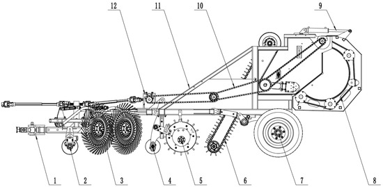
Figure 1.
Schematic diagram of the baling device structure. 1. Traction frame; 2. front depth limit roller; 3. collecting film plate; 4. back depth limit roller; 5. miscellaneous drum; 6. nail tooth chain plate film collecting mechanism; 7. ground wheel; 8. bundling mechanism; 9. hydraulic cylinder; 10. transmission system; 11. frame; and 12. reducer box.
2.2. Working Principle
The machine is attached to the tractor through a traction frame. During operation, power from the tractor’s power take-off (PTO) shaft is adjusted by the reducer. This power is then transmitted through a sprocket drive system to the active roller of the film-stripping mechanism and the drive wheel of the baling mechanism. The film-gathering disk converges all residual film toward the center. At the same time, the impurity removal roller ejects foreign materials such as fallen cotton, cotton stalks, and soil particles from the film. This process significantly reduces the impurity content during retrieval. The tooth-chain plate mechanism collects the residual film and transports it to the conveyor belt of the film-stripping unit. The active stripping roller and the compression roller work together to guide the film into the baling mechanism. Inside the baling mechanism, a mesh-type chain moves upward, lifting the residual film. Gravity, the friction between the chains, and the friction between the film layers cause the film to gradually wind into an initial core. At the same time, vibrations in the chain-mesh help dislodge adhered soil and other impurities. These impurities fall through gaps between the chain links. As the operation continues, more residual film is wound around the initial core. The diameter of the core increases steadily, forming a tight film bale. When baling is complete, a hydraulic cylinder above the baling mechanism retracts. This separates the baling mechanism from the stripping mechanism. The finished bale then drops under gravity and inertia, completing one operational cycle.
3. Bench Test and Membrane Bundle Motion Process Analysis
3.1. Determination of Bench Test Parameters
3.1.1. Bundling Mechanism and Working Principle
The winding mechanism is the most integral working part of the coreless winding device. The mechanism is mainly composed of s transmission mechanism, hydraulic membrane unloading mechanism, supporting roller, adjustable supporting roller, chain guard plate, net chain, sprocket chain support plate, side plate of winding mechanism, side plate connecting rod of the winding mechanism, and supporting sprocket. The structure diagram is shown in Figure 2.
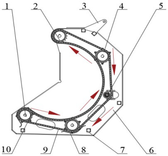
Figure 2.
Structure diagram of baling mechanism of coreless baling device. 1. Chain wheel; 2. transmission mechanism; 3. hydraulic unloading film mechanism; 4. supporting roller; 5. tensioning mechanism; 6. bundling device side plate; 7. bundling mechanism side plate connecting rod; 8. chain wheel chain plate; 9. net chain; and 10. chain guard plate.
After the residual film enters the bundling mechanism, it is driven by the chain-mesh to move circularly along its surface. When the residual film rises to a critical height, it falls back to the lowest point of the mechanism due to gravity and produces self-winding to form the initial core. With the continuous feeding of the residual film, the above-mentioned motion process is carried out circularly, and the core is continuously increased by layer-by-layer superposition, and finally a dense residual film bundle is formed. After completion of the operation, the hydraulic membrane unloading device starts to unload the finished membrane, and it realizes the single bundling test cycle.
3.1.2. Bench Test Parameters
As the film enters the bundling mechanism, it is ejected from the middle of the bundling mechanism when the chain-mesh’s speed is too slow. Consequently, the film fed in afterwards is blended with the former film and eventually accumulates at the bottom of the bundling mechanism. This results in the film being unable to be rolled up into bundles, as demonstrated in Figure 3. When the net chain operates at an excessively high speed, the linear velocity of the film’s edge is elevated, causing the film to be propelled to the top of the net chain and remaining at the outer periphery. Subsequent entries of the film also execute circumferential movement, resulting in the film ultimately undergoing irregular rotational movement within the bale-rolling organization, thereby hindering its formation into a bale. It is evident that the determination of the velocity of movement of the chain-mesh is paramount to the process of film roll-bundle formation. In order to more accurately simulate the effect of residual film conveying in actual operation, the linear speed of the net chain at the bale-rolling mechanism was determined to be 2 m/s, the amount of residual film fed was 0.5 kg/s, the linear speed of the conveyor movement was 1.6 m/s, and the test material was the residual film on the surface of the ground in the fall after the harvest of cotton, with a thickness of 0.015 mm. In order to facilitate the subsequent tracking of alterations in the trajectory of the film during the roll forming process, the front end of the film was colored red at approximately 150 mm. Filming was conducted using a V5.1 digital high-speed camera (1200 fps, 4G) manufactured by Vision Research, Inc. (Wayne, NJ, USA).

Figure 3.
Movement process of the film in the rolling and bundling mechanism. (A) At lower speeds, movement is observed in the chain-mesh. (B) In the event the chain-mesh moves at an accelerated rate.
3.2. Mechanical Analysis of the Membrane Bundle Formation Process
During the course of the operation, following the introduction of the residual film into the baling chamber, the film undergoes rotation within the chamber under the action of the chain net, thereby gradually forming the core. As the residual film continues to be fed, the newly introduced film is subjected to twisting, ultimately resulting in the formation of a film bundle. It can thus be concluded that the force of the residual film in the bale winding mechanism is the key factor in the formation of the film bale. As the residual film is continuously fed, each section of the movement remains in the same state. Therefore, in order to simplify the mechanical analysis, a section of the film should be selected, the coordinate system is established when the contact point between the residual film and the chain network and the residual film is separated from the chain network, and the stress situation in the two stages is analyzed, as demonstrated in Figure 4. This figure provides a schematic diagram of the film movement process force roll bundling mechanism.
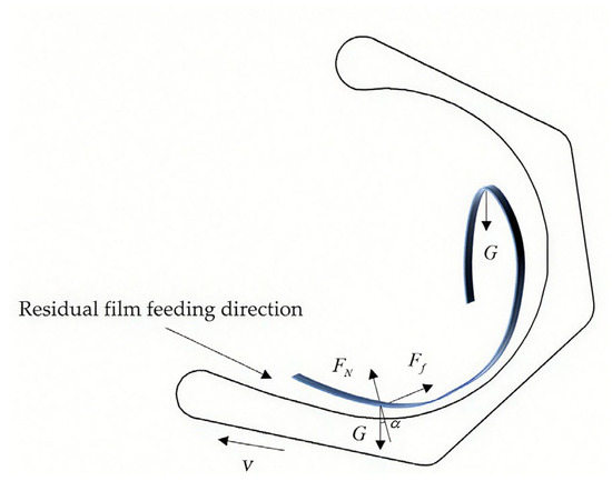
Figure 4.
Schematic diagram of the force of the film into the movement process of the rolling and bundling mechanism. Where v = the linear velocity of residual film movement (m/s).
- (1)
- Mulch moves in a circular motion with the chain-mesh.
In the range of 0 < α < 90°, the film begins to oscillate in a circular trajectory, concurrent with the chain-mesh’s engagement in the bale-rolling mechanism. The magnitude of the force exerted on the film during this phase is as follows:
where
= the combined force on the film in the bale-rolling mechanism (N);
= the pressure of residual film on the chain network (N);
= the frictional force exerted by the chain-mesh on the residual film (N);
= the gravity of the residual film (N);
= the mass of the mulch (kg);
= the linear velocity of the membrane as it moves (m/s);
= the angle between the gravitational force on the membrane and the opposite direction of the supporting force (°);
= the friction factor between the mulch and the chain-mesh;
= the circumferential radius of the film as it moves with the chain-mesh (m).
As demonstrated in Equations (1)–(3) and Figure 4, the movement of the film in the rolling and bundling mechanism is predominantly influenced by the interaction between the friction force of the chain-mesh on the film and the gravitational force of the film itself. At this juncture, the chain-mesh commenced a clockwise motion, synchronized with the film’s upward trajectory. This motion was initiated by the combined force F, which also augmented the film’s speed. Due to the reduced time of entry, the film’s quality diminished. Concurrently, the film and the chain-mesh moved towards the upper region of the bundling mechanism.
- (2)
- Mulch leaves the chain-mesh in a free-fall motion.
In the case were α = 90°, the film stage in the roll bundling mechanism undergoes net chain movement to the uppermost part of the mechanism, resulting in its separation from the chain. The film’s movement within the roll bundling mechanism is influenced by wind and other environmental factors triggered by the impact of the film. Utilizing its own gravitational force, the film undergoes a free-fall movement at this stage. The magnitude of the film’s force during this phase is as follows:
As demonstrated in Equation (4) and Figure 4, at this juncture, the film transitions to the uppermost position of the mechanism, ceasing its contact with the chain. Consequently, the film begins to recede under the influence of gravity, thereby finalizing the initial winding accumulation process and establishing the formation of the nascent film core. The subsequent feeding of the film in the rolling and bundling mechanism is characterized by the force and movement described above, and with the continuous entry of the subsequent film, the film undergoes a continuous winding and accumulation process in the rolling and bundling mechanism, ultimately forming a rotating film core.
3.3. High-Speed Camera Study of a Membrane Bundle Formation Process
To facilitate the observation of the kinematic behavior of the plastic film within the baling mechanism, an aperture was created on the side panel of the mechanism to enable high-speed cinematographic recording. A schematic diagram of the measurement system is presented in Figure 5.
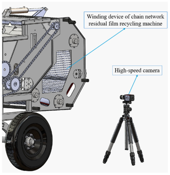
Figure 5.
Schematic diagram of the measurement system.
The residual film is conveyed to the film-stripping device by the conveyor belt, and it enters the bundling mechanism under the action of the conveying belt and film-stripping roller of the film-stripping device. It then winds and accumulates continuously to form the rotating film core gradually. As demonstrated in Figure 6, the position of the red-marked residual film is determined at a time interval of 0.5 s, according to the image obtained from the high-speed camera. The movement process of the residual film in the bundle-winding mechanism is subdivided into the following two phases: winding accumulation and film core formation.
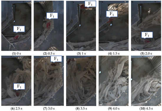
Figure 6.
Rotating film core formation process, where is the red labeled residual film.
The process under investigation has been shown to occur in the form of a winding accumulation phase, as follows: At 0–0.5 s, the residual film is fed into the bundle-rolling mechanism by the demolding mechanism, and under its own gravity and the friction between the residual film and the chain-mesh, the residual film is driven by the chain-mesh to move upward along its surface. In the time frame ranging from 0.5 to 1 s, ascends to the zenith of the rolled bundle mechanism, propelled by the net chain. Concurrently, the residual film disengages from the net chain. The gravitational force of the residual film itself constitutes the predominant force, thereby inducing a decline in the residual film’s velocity. At 1–1.5 s, falls from the top of the bale-rolling mechanism to the lowest end by its own gravity (ignoring forces such as wind inside the bale-rolling mechanism). At 1.5–2 s, falls on the residual film from the subsequent residual film feed, at which time the film core begins to wind and accumulate. At 2–3 s, the fell back to the bottom again due to the subsequent winding of the residual film and its own gravity, and then continued to move upward. This stage of analysis can be observed during the residual film accumulation winding process. The residual film is first subjected to approximate the circular motion by the net chain and then to falling motion by gravity. Subsequently, the film enters the drive and performs the above reciprocating motion. The height of its rise is determined by the residual film’s gravity and net chain friction. A substantial number of experiments have confirmed that, at this stage, the quality of the film is influenced by its own properties. Due to the limited amount of film, its movement is lighter, and the chain-mesh of the rolling mechanism continues to move upwards in a circular manner. The film core has not yet been fully formed.
The present study focuses on the following core formation stages: At 3.0–3.5 s, the film core was initially formed, with subsequent residual film feeding, and F1 was gradually rolled into the interior of the film to disappear in the camera range. In the 3.5–4.5 s interval, in conjunction with the subsequent residual film feeding, a complete film core is formed under the action of gravity, friction and residual film winding. The final experience time is 4.5 s. It is evident that the quality of the film is directly proportional to the quantity of material utilized, as evidenced by the analysis conducted using a high-speed camera. The edge of the film core has been determined to be at a speed of 1.2 m/s, which is approximately equivalent to 60% of the linear speed of the chain-mesh. This observation suggests that the film has not been adequately aligned with the core, resulting in a relatively loose interior. It is plausible that this deviation may be attributed to movement of the film core and chain-mesh during the process or the potential occurrence of slippage. In the present experiment, a substantial number of trials were conducted to ascertain the viability of the continuous entry and rotation of the film. The outcome of these trials was the successful formation of a rotating film core. At this juncture, the quality and volume of the rotating film core were found to be minimal, with its movement primarily concentrated in the central region of the chamber and the subsequent areas.
The preceding experiment yielded the following findings: The initial stage of rotating film core formation is predominantly characterized by the presence of residual film within the roll bundling mechanism. The net chain initiates a circumferential movement, which culminates at the highest point in a subsequent free-fall movement. Thereafter, the residual film descends to the lowest point, where it coils upon itself and the net chain, undergoing a reciprocating movement that is both circumferential and falling. This process marks the formation of the initial film core. In the context of residual film feeding, the residual film is subjected to continuous winding on the film core, thereby resulting in the formation of film bundles, as illustrated in Figure 7.
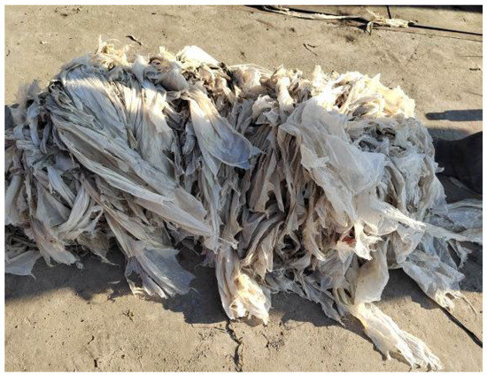
Figure 7.
Bench test of film-rolling and bundling.
4. Field Test and Parameter Optimization Analysis
4.1. Field Test Conditions
In October of 2023, a field trial of film recycling was conducted in the second company of the third division of Beiquan Town, Shihezi City, Xinjiang. The equipment and instruments utilized in the trial encompassed the following: A 4CMK100 type recycling machine for farmland film operation, a 50 cm tape measure with a minimum scale of 1 mm, a 20 cm straightedge with a minimum scale of 1 mm, and a sprocket speed-testing device. At the time of operation, the cotton in the field had been harvested, and the drip irrigation belt had been pumped out. Prior to harvesting the film, the straw should be crushed and returned to the field by the disk-type rod raking machine. Concurrently, the film should be collected and striped, with 6 rows of one-way operation. The working distance of each row was measured to be 420 m, and the width of the collected strips was approximately 35~40 cm. The bale winder, which is affixed to the rear of the implement, is utilized in conjunction with a John Deere 954 tractor. The planting pattern that was selected for this experiment was designated as “66 cm + 10 cm”. The mulch was applied in April of 2023, with a thickness of 0.015 mm, a width of 2050 mm, and a height of 600–800 mm for the straw, as illustrated in Figure 8.
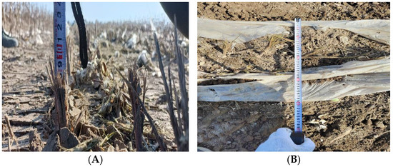
Figure 8.
Parameters of the test field. (A) Straw height measurement after crushing. (B) Measurement of the width of film-collecting strips.
4.2. Determine the Test Procedures
Preliminary experimental findings indicate a correlation between the residual film final reeling operation and the following three distinct variables: the forward speed of the machine X1, the speed of the active film-removing roller X2, and the speed of the film reeling support roller X3. During the operation of the entire apparatus, the power of the film-removal mechanism and bale-rolling mechanism is transmitted by the rear output shaft of the tractor. The velocity of the film-removal roller and film-rolling support roller can be modified by adjusting the sprocket in the test apparatus. Consequently, the following three operational parameters were selected for the experimental investigation: the forward speed of the machine, the rotational speed of the active film-stripping roller, and the rotational speed of the film winding support roller.
- (1)
- The present study investigates the impact of the machine’s forward speed on the effectiveness of residual film recycling.
The 4CMK100 type farmland film operation recycling machine is towed by the tractor. When the machine’s forward speed is insufficient, the machine’s picking efficacy is diminished, thereby compromising the efficiency of residual film recycling and exerting a negative influence on the film bundle bundling effect. In scenarios where the machine’s forward speed is elevated, the velocity is excessive, resulting in a paucity of time. Consequently, a portion of the straw, branches, leaves, and other impurities are conveyed with the residual film to the bundling device. The film is then consolidated into bundles with elevated impurity levels. Simultaneously, when the velocity is excessively fast, the film does not coalesce into rolls, thereby compromising the efficacy of the recycling operations. To circumvent these issues, a machine forward speed from 5 to 6 km per hour was selected for the experimental phase.
- (2)
- The present study investigates the impact of the rotational speed of active film removal rollers on the effectiveness of residual film recovery.
The stripping mechanism is positioned between the film picking mechanism and the bundling mechanism. According to the test results, when the active stripping roller of the stripping mechanism operates at a speed lower than 100 r/min, the residual film is susceptible to being blocked when it reaches the conveyor belt due to the limited contact distance between the film roller and the belt. This hinders the film from reaching the bundling mechanism, thereby compromising the efficacy of the bundling operation. In the event that the velocity of the active film removal roller of the film removal mechanism is excessively high, the torque required to facilitate the process increases, thereby placing greater strain on the transmission system. Concurrently, the friction between the conveyor belt and the film roller escalates, leading to accelerated wear and a reduction in the belt’s lifespan. Consequently, an active film removal roller speed from 130 to 190 r/min was selected for the experimental investigation.
- (3)
- The present study investigates the impact of the rotational velocity of the rollers that provide support to the film on the effectiveness of residual film recovery.
The rotational speed of the bale-rolling mechanism constitutes the core component of the bale-rolling device, and it exerts a substantial influence on the residual film recycling operation. It has been demonstrated that when the rotational speed of the bale-rolling support roller is increased, the film core is formed more rapidly, resulting in a tighter bale. Consequently, the film conveyed by the subsequent stripping device can be more efficiently coiled on the formed bale, thereby enhancing the bale-rolling effect. It has been determined that when the velocity exceeds a certain threshold, the quality of the pre-film bundle is reduced due to the centrifugal force generated by the roll bundle mechanism. This results in the film bundle machine and the subsequent entry into the film following the net chain rotation. This phenomenon is not conducive to the film bundle molding process, which leads to the deterioration of the operating effect. Therefore, the selection of the roll bundle support roller speed was conducted within the range of 160–260 r/min for the test. In order to better investigate the effects of the aforementioned three factors on the density of recycled residual film bundles, a mathematical model was constructed by the response surface method. In this study, the forward speed of machine X1, the speed of the active film-stripping roller X2, and the speed of the film-rolling support roller X3 were selected as the test factors. The density of film bale Y was taken as the response index. A three-factor, three-level Box–Behnken experimental design was used to combine the tests [23,24]. The three factors were level coded, and the coding table of each factor is shown in Table 1.

Table 1.
Test factor coding table.
The majority of extant operational standards for reeling pertain to forage round baling methods; consequently, there is a paucity of mechanized residual film reeling operational standards. A comprehensive evaluation of the pertinent data reveals a compelling correlation between the operational effectiveness of the residual film recycling process and its impact. The degree of tightness of the residual film roll (i.e., the film bale density) and the rate of film bales are pivotal indicators of the performance of the residual film-rolling and baling device. This test is based on the “GB/T 25412-2021 Farm waste film-pick up machines” [25] and “GB/T 14290-2021 Round baler” [26] to develop an experimental test program. The test utilizes a single-factor and multi-factor combination of test methods due to the characteristics of the residual film itself. It is known that the film bale density is 100% during the rolling device operation. The single-factor and multi-factor combination test methods are employed due to the characteristics of the residual film itself. The film bale formation rate is 100% when the bale-rolling device is operating. Therefore, the residual film bale density is selected to evaluate the quality of the bale-rolling device operation indexes.
The residual film bundle density, designated as Y, is calculated as follows:
where
= the denotes Mulch Bundle Density measured (kg/m3);
= the represents Mulch Bale Quality (kg);
= the signifies Mulch Bundle Diameter (m);
= the indicates Mulch Bundle Length (m).
The empirical evidence from the operation and testing indicates the presence of a specific phenomenon in the film bundles post-baling and molding: the presence of two soft ends and a tight center. To ensure the validity of the test results, the film bundles will undergo measurement of the diameter distribution range, with the density being sought within the length of each area. The calculation of the mean value will then be conducted.
4.3. Experimental Results and the Optimization of Parameters
The statistical outcomes of the density of the film bundles recovered by the bale-rolling device of the cotton field residual film recycling machine under the interaction of different operating parameters are presented in Table 2. In conjunction with the data in the table, multiple regression fitting analysis was executed using Design-Experts experimental design software, and the response surface regression equations were established for the density of the residual film bundles and the three factors of the forward speed of the machine, the rotational speed of the active stripping roller, and the rotational speed of the rolled film support roller. Y signifies the Mulch Bundle Density measured (kg/m3). X1 represents the Machine Forward Speed (km/h). X2 denotes the Active Film-Stripping Roller Speed (r/min). X3 indicates the Rotating Speed of Film-Rolling Support Rollers (r/min). The regression equation is shown in Equation (6), and the ANOVA results are shown in Table 3.
Table 2.
Test results.
Table 3.
Analysis of Variance (ANOVA) for film bundle density.
An examination of the p-values of the factors in Table 3 reveals that the p-values of the forward speed of the machine X1, the speed of the active film-release roller X2, the speed of the film support roller X3, the interaction term between the speed of the active film-release roller and the speed of the film support roller X2X3, the forward speed of the machine X12, the second term of the speed of the active film-release roller X22, and the second term of the speed of the film support roller X32 are all less than 0.01, which indicates that the forward speed of the machine, the speed of the active film-release roller, and the speed of the film support roller have a highly significant effect on the density of film bales. The p-value of the interaction term X1X2, which represents the relationship between the forward speed of the machine and the speed of the active stripping roller, is less than 0.05. This indicates that the aforementioned factors have a significant impact on the density of the film bundles. In contrast, the p-values for the remaining factors are all greater than 0.05, suggesting that their effect on the density of film bundles is not significant. A comparison of the regression coefficients reveals the following order of influence on the density of film bundles: the speed of film roll support roller X3 > the speed of active stripping roller X2 > the forward speed of machine X1.
As demonstrated in Table 3, the film bale density p < 0.0001, signifying that the quadratic regression equation test of the model attained a highly significant result. The loss of fit test p > 0.05, indicating that the model exhibits a satisfactory fit within the scope of this test. Concurrently, the coefficient of determination of the model can be observed in the Design-Experts software analysis report, R2 = 0. 9929, and the model error is minimal, indicating that this model can be used to predict and analyze the film bale density of the residual film recycling bale-rolling device in cotton fields.
In order to more intuitively and effectively analyze the relationship between the influencing factors and the influencing indicators, Design-Expert software was used to analyze and obtain the surface diagram of the response of each factor to the density of rolled bundles, as shown in Figure 8. As depicted in Figure 9A, in the absence of the film supporting roller’s rotation, an increase in the machine’s forward speed results in a gradual decline in the density of film bundle Y. This decline is less pronounced when the active stripping roller’s speed is augmented. The density of film bundle Y exhibits an initial increase, followed by a subsequent decrease, when the active stripping roller’s speed is increased. This observation indicates that the impact of the active stripping rollers’ speed on the density of the film bundles Y is more substantial than that of the machine’s forward speed at the test level. The X1 model is more significant. An analysis of Figure 9B reveals that when the rotational speed of the active stripping roller is at a zero level, an increase in the forward speed of the machine X1 results in a gradual decrease in the density of film bundles Y. However, the range of values that can be observed is limited, and the decline in density is gradual. Conversely, when the film supporting the roller’s speed is augmented, the density of film bundle Y undergoes a gradual decline, exhibiting a faster rate of change. This phenomenon can be likened to the analysis of the film supporting rollers’ speeds at this level of film bundle density. It is evident that Y holds greater significance in comparison to X1. Conversely, Y exhibits a greater significance compared to X1. An analysis of Figure 9C reveals that, when the machine’s forward speed is at a zero level, an increase in the speed of the active stripping roller X2 results in an increase in the density of the film bundle Y, followed by a subsequent decrease. However, the range of values exhibits minimal variation, and the rate of change is gradual. Conversely, when the film supporting roller speed is increased, the density of the film bundle Y exhibits a rapid decline in trend, with a concomitant increase in the magnitude of the change. This analysis indicates that, at the experimental level, the effect of the film supporting rollers on density Y is more significant than that of active stripping roller speed X2. Therefore, it can be concluded that, at this test level, the effect of film supporting roller speed X3 on film bundle density Y is more significant than that of active film-stripping roller speed X2. Based on the above analysis, it can be concluded that the factors influencing the bale density, in descending order of impact, are the rotation speed of the film-support roller (X3), the rotation speed of the active film-removal roller (X2), and the machine forward speed (X1).
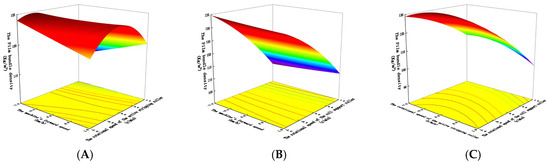
Figure 9.
Effect of factors on the density of film bundles. (A) The impact of the machine’s forward speed and the rotational speed of the active stripping rollers on the density of film bundles. (B) The machine’s forward speed and the rotational speed of the roll support roller on the density of film bundles. (C) The impact of the rotational speed of the active stripping rollers and the rotational speed of the roll support roller on the density of the film bundle.
In order to enhance the operational efficacy of the residual film recycling bale-rolling device in cotton fields, its operating parameters were optimized and analyzed. The data optimization module in Design-Expert experimental design software was utilized to enhance the operational efficiency of the bale reeling apparatus, thereby identifying the optimal solution [27,28]. The maximum value of the film bale density, designated as Y, was identified as the operation objective. The values of the optimization interval for each factor were constrained to the upper and lower limits of the experimental factors. The result of this optimization indicates that the film bale density is optimal when the forward speed of machine X1 is 5.85 km/h, the rotational speed of active stripping roller X2 is 167.4 r/min, and the rotational speed of roll support roller X3 is 208.74 r/min.
4.4. Field Trial Validation
In order to verify the correctness and reliability of the software optimization results, taking into account the actual situation of the bale-rolling device, the optimization value obtained by the software is rounded up. The forward speed of the machine is 5.8 km/h, the speed of the active film-removing roller is 170 r/min, and the speed of the film-rolling support roller is 210 r/min. The experiment was conducted in the post-harvest cotton field of the three sections of the town of Beiquan, Shihezi, Xinjiang, in October 2023. The residual film was recovered and rolled up in the field. The efficacy of recycling rolled bales is demonstrated in Figure 10.
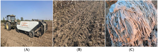
Figure 10.
Bundling operation effect. (A) Residual film recycling machine. (B) Post-operational surface. (C) Mulch bale.
Subsequent to the implementation of a field test, the mean of five test results was calculated, yielding a final test residual film bale density of 124.44 kg/m3 and a relative error of 1.34 kg/m3 with respect to the predicted value. This verifies the accuracy of the constructed model. The optimized residual film bale-rolling device in cotton fields exhibited enhanced performance and satisfied the criteria for residual film recycling and bale-rolling operations. However, due to the dynamic nature of the field conditions, residual film was observed to be released from the gap between the molding and stripping device at the molding device, influenced by wind forces and sand expelled during the cleaning process. This resulted in some residual film adhering to the machine’s shell, impeding the feeding process into the bale-rolling device and consequently affecting the quality of the residual film that was rolled and baled.
5. Conclusions
(1) To address the issues of high-impurity content in residual plastic film, the complex structure with difficult maintenance, and low continuous operational efficiency in existing recovery equipment, this study designed and validated a chain-mesh-type residual film winding and baling device. Bench tests and field verification confirmed that the device utilizes the frictional driving force between the chain mesh and the residual film to achieve automatic film winding and baling, effectively resolving the core technical problems of existing residual film recovery devices. It provides a technically stable and easily maintainable solution for mechanized residual film recovery.
(2) Through a combination of bench testing and high-speed photography, the dynamic mechanism of coreless baling was revealed as follows: after entering the baling mechanism, the residual film undergoes three stages—circular motion, free fall, and continuous winding. The initial film core formation takes 4.5 s, corresponding to a film feed amount of 2.25 kg and an initial film core edge linear velocity of 1.2 m/s. Subsequently, as the residual film accumulates, it enters a high-speed rotation baling stage. This study quantified the dynamic motion parameters of the residual film, further refining the theoretical system of coreless residual film baling and providing a dynamic mechanical basis for optimizing the rotational speed of the film-support roller.
(3) Using the “66 cm + 10 cm” machine-harvested cotton fields in Shihezi, Xinjiang, with a film thickness of 0.015 mm as the test scenario, three operational parameters were selected as follows: machine forward speed, active film-removal roller speed, and film-support roller speed. With bale density as the evaluation indicator, the operational performance of the chain-mesh baling device was analyzed and optimized via Design-Expert software. The results showed that the optimal bale density was achieved when the machine forward speed was 5.8 km/h, the active film-removal roller speed was 170 r/min, and the film-support roller speed was 210 r/min. The tested residual film bale density was 124.44 kg/m3, with a relative error of 1.34 kg/m3 compared to the predicted value, verifying the accuracy of the established model. Field tests demonstrated that the chain-mesh baling device operates stably, possesses strong structural applicability, and meets the requirements for mechanized residual film collection.
Although the coreless baling device designed in this study achieved the primary objective of coreless baling of waste plastic film, and its operational effectiveness and structural reliability were verified through theoretical analysis and experimental testing, limitations in time and field conditions revealed areas for improvement in the prototype’s practical application. Firstly, impurities can easily compromise the operational stability of the chain-mesh. During operation, residual film delivered to the baling mechanism often contains fragmented straw and soil. These impurities can enter the double-row sprocket of the support roller, causing abnormal engagement clearance between the sprocket and the chain mesh, leading to jerky movement of the chain-mesh and affecting the continuity of the baling process. Secondly, variability in bale formation time makes it difficult to control the unloading timing. Field tests indicated that the complex operating environment of Xinjiang cotton fields results in varying amounts of straw and soil mixed with the residual film in different scenarios. Fluctuations in impurity content affect the bale formation time, making it challenging for operators to accurately determine the optimal unloading time. Unloading too early results in loose bales, while unloading too late may cause jamming due to overfilling, reducing operational efficiency.
Future research will focus on structural improvements and functional optimization, outlined as follows: Enhancing impurity resistance by improving the protective design of the double-row sprocket on the support roller, adding dust-proof components, and optimizing the tensioning mechanism to ensure stable transmission of the chain mesh under minor impurity interference. Adding a bale size warning function by installing a size-monitoring device on the side panel of the baling mechanism to track the bale diameter in real time. When the predetermined size is reached, a warning signal will be triggered to assist operators in accurately controlling the unloading time, avoiding efficiency losses due to human judgment errors.
Author Contributions
Conceptualization, Y.Z.; methodology, Y.Z. and X.C.; software, Y.Z. and X.T.; validation, X.T. and X.L.; writing—original draft preparation, Y.Z.; writing—review and editing, Y.L. and G.H.; supervision, X.C.; funding acquisition, Y.Z. and X.T. All authors have read and agreed to the published version of the manuscript.
Funding
This research was funded by the Xinjiang Uygur Autonomous Region Tianchi Talent Project (CZ002549), Xinjiang Production and Construction Corps Science and Technology Program Project Science and Technology Innovation Talent Program (2023CB008-09), Youth Project of the Excellence Support Program of Xinjiang Production and Construction Corps (CZ002528), Bingtuan Natural Science Support General Program (2024DA023), and Project supported by Self-supported Research Project by Shihezi University (ZZZC2023003).
Data Availability Statement
The original contributions presented in this study are included in the article. Further inquiries can be directed to the corresponding author.
Conflicts of Interest
The authors declare no conflicts of interest.
References
- Hu, Q.; Li, X.; Shi, H.; Chen, N.; Zhang, Y.; Ma, H. Response of Corn Root System to Residual Film and Root Distribution Model in Hetao Irrigation Area. Agric. Eng. J. 2021, 37, 143–152. [Google Scholar] [CrossRef]
- Liang, R.Q.; Chen, X.G.; Zhang, B.C.; Meng, H.; Jiang, P.; Peng, X.; Kan, Z.; Li, W. Current Issues and Strategies for Residual Film Recovery and Resource Utilization in Xinjiang Cotton Fields. Agric. Eng. J. 2019, 35, 1–13. [Google Scholar] [CrossRef]
- Wang, L.; Lin, T.; Yan, C.R.; Wang, J.; Guo, R.; Yue, L.; Tang, Q. Effects of Residual Film Amount on Evapotranspiration and Inter-Row Evaporation in Xinjiang Cotton Fields. Agric. Eng. J. 2016, 32, 120–128. [Google Scholar] [CrossRef]
- Du, L.; Li, Y.N.; Chen, P.P.; Wang, K.; Li, Y. Effects of Different Residue Film Amounts on Soil Environment and Corn Growth. Water Sav. Irrig. 2018, 7, 4–9+14. [Google Scholar]
- Li, W.; Li, M.; Zhao, H.; Sun, D.; Li, S.; Han, X. Plastic Film Covering Planting Technology and Residual Film Pollution Prevention and Control. Agric. Eng. J. 2024, 14, 65–71. [Google Scholar] [CrossRef]
- Wang, Z.H.; He, H.J.; Zheng, X.R.; Zhang, J.; Li, W. Impact of Returning Cotton Stalks to Soil on Residual Film Distribution in Mulched Drip Irrigated Cotton Fields in Typical Oases of Xinjiang. Agric. Eng. J. 2018, 34, 120–127. [Google Scholar] [CrossRef]
- Zhao, Y.; Chen, X.; Wen, H.; Zheng, X.; Niu, Q.; Kang, J. Research Status and Prospect of Control Technology for Residual Plastic Film Pollution in Farmland. Trans. Chin. Soc. Agric. Mach. J. 2017, 48, 1–14. [Google Scholar] [CrossRef]
- Chang, L. Preliminary Study on the Development of Residual Film Recovery Machine. Agric. Sci. Technol. Equip. 2013, 2, 37–38. [Google Scholar] [CrossRef]
- Zhou, J.; Xie, J.; Zhao, W.; Zhang, Y.; Cao, S.; Lin, Y. Design and test of winding device for round bale residual film baler. J. Chin. Agric. Mech. 2025, 46, 20–29. [Google Scholar] [CrossRef]
- Tang, Y.; Zhao, Y.; Wang, Z.; Wang, J. Design and experiment of film removing device for clamping finger-chain type residual film collector. Agric. Eng. J. 2020, 36, 11–19. [Google Scholar] [CrossRef]
- Lavo, G. Machine for Removing Wide Strips Laid out on the Ground. U.S. Patent No. 5,386,876, 7 February 1995. [Google Scholar]
- Rocca, A.R. Plastic Mulch Retriever. U.S. Patent No. 8,302,699, 6 November 2012. [Google Scholar]
- Ying, Y.; Cao, S.; Wang, M.; Lu, Y. Developing of 1LM-5.0 Film Raking Machine. Xinjiang Agric. Mech. 2016, 4, 11–12. [Google Scholar] [CrossRef]
- Wang, Z.; Wang, J.; Tang, Y.; Luo, Y. Design and test of the belt-type residual film rubbing and baling machine. Agric. Eng. J. 2020, 36, 11–18. [Google Scholar] [CrossRef]
- Zhou, J.; Xie, J.; Cao, S.; Zhang, Y.; Zhang, Y.; Liu, W. Design and experiment of roll-shaft-type packing device for residual film. J. S. China Agric. Univ. 2024, 45, 148–158. [Google Scholar] [CrossRef]
- Zhang, J.; Yang, C.; Guo, J.; Jiang, Y.; Zhang, H.; Zhang, L. Design and experiment of hob-type joint operation machine for silage corn root stubble plucking and residual plastic film collecting. Agric. Eng. J. 2018, 34, 25–34. [Google Scholar] [CrossRef]
- Zhang, X.; Kang, M.; Shi, Z.; Yan, J.; Liu, X.; Guo, L.; Wang, M. Design and experiments of a double drum surface residual film recycling machine after harvest. Trans. Chin. Soc. Agric. Eng. 2024, 40, 1–13. [Google Scholar] [CrossRef]
- Wang, X.; Liu, J.; Liu, X.; Jiang, Y.; Zhang, H.; Zhang, J.; Zhang, L. Design and test of a coreless-roll packing device for residual film. Transactions of the Chinese Society of Agricultural Engineering. Agric. Eng. J. 2022, 38, 28–35. [Google Scholar] [CrossRef]
- Tian, X.; Zhao, Y.; Chen, X.; Yan, L.; Wen, H.; Gao, H.; Ji, C. Development of 4JSM-2000A type combined operation machine for cotton stalk chopping and residual plastic film collecting. Agric. Eng. J. 2018, 34, 25–35. [Google Scholar] [CrossRef]
- Huo, S.; Ying, Y.; Wang, M.; Wang, J.; He, Y.; Liu, P.; Tang, Z.; Lu, Y. Design and test of residual film recovery baling box and straw crushing combined operation machine. Farm Mach. 2020, 36, 11–18. [Google Scholar] [CrossRef]
- Liu, X.; Tian, X.; Zhao, Y.; Li, Y.; Ma, H. Research on Film Collection Device of Residual Film Recycling Machine. Agric. Eng. 2024, 14, 5–14. [Google Scholar] [CrossRef]
- Xie, J.; Liu, W.; Cao, S.; Huang, W.; Zhang, J.; Li, Y.; Meng, Q. Design and Test of Countercurrent Hook-type Residual Film Mixture Cleaning and Separation Device. Trans. Chin. Soc. Agric. Mach. 2025, 56, 397–408. [Google Scholar] [CrossRef]
- Tian, Y. Optimization of the Hot Stamping Forming Process for High Strength Steel Laser Tailored Welding Plate B-Pillar Based on Response Surface Methodology. Master’s Thesis, Changchun University of Technology, Changchun, China, 2023. Available online: https://kns.cnki.net/kcms2/article/abstract?v=d7HKHDfP4kc7YoBN4c91IY-atQET9VFmxSy07pBrDT6h2JpRhW_nFIPOXt65J1pREZl_UYVa3Hct4jgRBZYzkQzdDYEZe7kBTWylKVwKfDAZNdxECOZQ3Cywl1Pc-NfJiELM8ppuNRPzqKJK8Q-I1Tv6pyBWm44LcD0Pm1X0J781FewyDyXq4Obl419YdU9e0-VNPPE7p7c=&uniplatform=NZKPT (accessed on 8 September 2025).
- Zhu, Y.; Chen, J.; Li, X.; Peng, T. Application of Response Surface Method in Processing Parameters Optimization of H13 Die Steel Wire Arc Additive Manufacturing. Tool Eng. 2023, 57, 21–27. [Google Scholar] [CrossRef]
- GB/T 25412-2021; Farm Waste Film-Pick up Machines. Standards Press of China: Beijing, China, 2021. Available online: https://openstd.samr.gov.cn/bzgk/std/newGbInfo?hcno=E87AAA6CC56A907C5302D520AAD7A7AB (accessed on 31 December 2021).
- GB/T 14290-2021; Round Baler. Standards Press of China: Beijing, China, 2021. Available online: https://openstd.samr.gov.cn/bzgk/std/newGbInfo?hcno=0E803426D390794EE0D1729901B7AFF7 (accessed on 21 May 2021).
- Yan, W.; Hu, Z.; Wu, N.; Xu, H.; You, Z.; Zhou, X. Parameter optimization and experiment for plastic film transport mechanism of shovel screen type plastic film residue collector. Agric. Eng. J. 2017, 33, 17–24. [Google Scholar] [CrossRef]
- Shi, L.; Hu, Z.; Gu, F.; Wu, F.; Wu, P. Design and parameter optimization on teeth residue plastic film collector of ridged peanut. Trans. Chin. Soc. Agric. Eng. 2017, 33, 8–15. [Google Scholar] [CrossRef]


Disclaimer/Publisher’s Note: The statements, opinions and data contained in all publications are solely those of the individual author(s) and contributor(s) and not of MDPI and/or the editor(s). MDPI and/or the editor(s) disclaim responsibility for any injury to people or property resulting from any ideas, methods, instructions or products referred to in the content. |
© 2025 by the authors. Licensee MDPI, Basel, Switzerland. This article is an open access article distributed under the terms and conditions of the Creative Commons Attribution (CC BY) license (https://creativecommons.org/licenses/by/4.0/).