Article

Numerical Simulation of Darcy–Forchheimer 3D Unsteady Nanofluid Flow Comprising Carbon Nanotubes with Cattaneo–Christov Heat Flux and Velocity and Thermal Slip Conditions

1
School of Mathematical Sciences, University of Science and Technology of China, 96 Jinzhai Road, Hefei 230026, China
2
Department of Mathematics and Social Sciences, Sukkur IBA University, Sukkur 65200, Pakistan
3
Department of Mathematics, Quaid-i-Azam University 45320, Islamabad 44000, Pakistan
4
Department of Computer Science, Bahria University, Islamabad 44000, Pakistan
5
Department of Mechanical Engineering, Sejong University, Seoul 143-747, Korea
6
Faculty of Science, Jiangsu University, Zhenjiang 212013, China
7
Department of Mathematics, COMSATS University, Islamabad 45550, Pakistan
8
Department of Mathematical Sciences, Faculty of Science and Technology, Fatima Jinnah Women University, Rawalpindi 46000, Pakistan
*
Authors to whom correspondence should be addressed.
Processes 2019, 7(10), 687; https://doi.org/10.3390/pr7100687
Submission received: 20 August 2019 / Revised: 8 September 2019 / Accepted: 17 September 2019 / Published: 2 October 2019
(This article belongs to the Special Issue Fluid Flow and Heat Transfer of Nanofluids)

Abstract

:
A mathematical model comprising Darcy Forchheimer effects on the 3D nanofluid flow with engine oil as a base fluid containing suspended carbon nanotubes (CNTs) is envisioned. The CNTs are of both types i.e., multi-wall carbon nanotubes (MWCNTs) and single-walled carbon nanotubes (SWCNTs). The flow is initiated by an exponentially stretched surface. The impacts of Cattaneo–Christov heat flux along with velocity and thermal slip conditions are key factors in the novelty of the defined model. The boundary layer notion is designed to convert the compact form of equations into the component shape. Appropriate transformations lead to differential equations with high nonlinearity. The final non-dimensional system is solved numerically by a “MATLAB” function known as bvp4c. For both CNTs, different graphical sketches are drawn to present the influence of arising parameters versus related profiles. The outcomes show that higher slip parameter boosts the axial velocity, whereas fluid temperature lowers for a sturdier relaxation parameter.

1. Introduction

The process of heat transfer is basically the movement of heat from the reservoir with high temperature to the reservoir with low temperature. Owing to its significance in numerous engineering applications, for example in the bio-medical sector for magnetic drug targeting, nuclear reactor cooling, and energy production, attention is paid to forecasting the behavior of heat transport in various scenarios. In 1822, Fourier [1] first proposed the law of heat conduction. This rule provides a path to understanding the phenomenon of heat transfer and became the basis for learning on heat conduction in the next two centuries. However, there was a deficiency in Fourier’s law that resulted in a parabolic equation for the temperature field. This indicates an initial disruption in the beginning, continuing throughout the medium under a consideration which is a contradiction to the causality principle. To address this unrealistic characteristic, known as the “paradox of heat conduction”, Cattaneo [2] presented a relaxation time term in the orthodox Fourier’s law, and this new model was termed the modified Fourier’s law or Cattaneo’s law. Later, Christov [3] introduced the Oldroyd’s upper-convected derivative [4] for a material derivative in the Cattaneo’s law. This latest proposed model is known as the Cattaneo–Christov heat flux model. The Cattaneo–Christov heat flux model’s uniqueness was examined by Zampoli and Tibullo [5]. The structural stability of the governing temperature equation comprising the Cattaneo–Christov model was examined by Straughan and Ciarletta [6]. The numerical solution for thermal convection of an incompressible aqueous fluid by employing Cattaneo–Christov heat flux was found by Straughan [7]. This was followed by many explorations ([8,9,10,11] and many therein).
Carbon nanotubes (CNTs) are a type of nanoparticle firstly introduced in 1991. Carbon nanotubes are thin and rod-shaped, made up of pure carbon with a diameter of 0.7–50 nm. CNTs possess distinct significance in optics, composite materials, nanotechnology, antifouling shade, conductive plastics, and atomic force microscope, etc. CNTs are also commonly used in radio antennas and similar electromagnetic gadgets. CNTs also provide benefits in many engineering applications like resistors, high-temperature refractors, and medical device biosensors. CNTs are subdivided into two groups: single-walled carbon nanotubes and multi-wall carbon nanotubes. Choi et al. [12] found that CNTs are the prime source for maximum thermal conductivity enhancement in comparison to contemporary nanoparticles. The function of homogeneous CNTs in the case of electrical applications was studied by Ramasubramaniam et al. [13]. He noticed remarkable enhancement in electrical conductivity for single-walled carbon nanotubes. Kamali and Binesh [14] highlighted the role of multi-wall carbon nanotubes for the improvement of thermal conductivity in a non-Newtonian fluid flow. They claimed that wall regions in case of non-Newtonian multi-wall carbon nanotubes nanofluid flow play a pivotal role in triggering the heat transfer rate. The study of heat transfer and pressure drop in a CNT-based nanofluid flow through a circular tube was studied by Wang et al. [15]. They found that average convective heat transfer is more visible in the case of nanofluid flow in comparison to the distilled water. Haq et al. [16] scrutinized the role of CNTs in water-based nanofluid squeezed flow. They noticed that the heat transfer rate in the case of single-walled carbon nanotubes is larger as compared to MWCNTs. A study of CNT water-based nanofluid flow past a vertical cone with solutal stratification and gyrotactic microorganisms was carried out by Ramzan et al. [17]. It was revealed by them that skin friction coefficient is a decreasing function of bio convective Rayleigh number. Bilal et al. [18] outlined a numerical solution of the CNT-based nanofluid flow with Hall current impact and Darcy–Forchheimer permeable medium past a vertically convected stretching surface. The novelty of the said problem is improved by the adding the nonlinear thermal radiation and the dust particles in the nanofluid flow. They remarked that the thermal field for nanofluid is larger in comparison to the dust phase. Taseer et al. [19] found an optimal series solution of the aqueous-based nanofluid 3D flow containing CNTs through a Darcy–Forchheimer spongy medium with the convective condition. The impact of buoyancy effect embedded with activation energy and non-Darcy porous medium past a stretched surface was studied numerically using the numerical technique by Lu et al. [20]. Recently, Hayat et al. [21] numerically found the solution of Darcy–Forchheimer nanofluid flow comprising nanotubes over an exponentially stretching sheet [22,23,24,25,26].
The flow of fluids in a permeable medium has abundant significant applications in industry and environmental science, including heat exchange layouts, groundwater systems, geothermal energy systems, nuclear waste disposal, erection of oil reservoirs in insulating systems, catalytic reactors, and movement of water in reservoirs, etc. The non-Darcian porous medium containing inertia and boundary characteristics is a modified form of orthodox Darcy model. Considerable attention has been paid in recent years to the models comprising porous media with conventional Darcy’s law. The Darcy’s law is valid only for minimal velocity and diminutive porosity and fails to address models with high Reynolds’s number. To overcome this deficiency, Forchheimer [27] improved the momentum equation by adding the squared term. This new addition to the momentum equation is known as the “Forchheimer term”, as named by Muskat [28]. Seddeek [29] analyzed the Darcy–Forchheimer flow with impressions of viscous dissipation and mixed convection. The flow of Darcy–Forchheimer hydromagnetic fluid with the upshots of non-uniform source/sink and unsteady viscosity was deliberated numerically by Pal and Mondal [30]. Waqas et al. [31] deliberated an optimal solution of the nanofluid fluid flow containing both types of CNTs over a rotating disk. The flow of non-Newtonian Maxwell fluid flow past an protracted surface with effects of Newtonian heating and chemical reaction is analyzed by Sadiq et al. [32]. They found that the velocity profile shows differing impacts versus the Deborah number and porosity parameter. Rashid et al. [33] examined numerically 3D rotating flow with Darcy–Forchheimer porous media and a binary chemical reaction. They gathered that the velocity of the fluid is a dwindling function porosity parameter. It is also noted that with an increasing reaction parameter the concentration is decreased. Farooq et al. [34] analytically found the series solution of the Darcy–Forchheimer nanofluid flow within parallel plates in attendance of melting heat and double stratification. They evaluated that the temperature of the fluid is on the decline because of melting heat parameter. It is further noticed that the temperature and concentration of the fluid are augmented owing to Brownian motion parameter. Nasir et al. [35] studied the Darcy–Forchheimer nanofluid thin-film flow due to an unsteady stretching surface with single-walled carbon using the Homotopy Analysis scheme. Recently, Montessori et al. have worked on Lattice Boltzmann formulations for flows beyond the Darcy regime (see for example [36,37,38]).
The aforesaid literature review discloses that there have been attempts in the past involving Cattaneo–Christov heat flux in 2D but fewer articles are available discussing the 3D geometry. This topic becomes more specific in the presence of Darcy Forchheimer effect in the nanofluid flow comprising CNTs. The uniqueness of the problem is raised when we discussed the whole scenario in the presence of velocity and thermal slips. To our information no such study is conducted so far that discusses the feature of a Cattaneo–Christov-based model in a nanofluid flow with CNTs of both types embedded in a Darcy–Forchheimer permeable medium with velocity and thermal slips. The exploration is carried out for the 3D unsteady incompressible nanofluid. Similarity transformation is implemented on the governing partial differential equations to get a dimensionless form of ordinary differential equations which are highly non-linear. These equations are tackled numerically by the bvp4c function of MATLAB. The impacts of different parameters are shown graphically and discussed in length. Some iterations of the physical parameters like the skin friction coefficient and Nusselt number are also given in tabulated form for multi-wall carbon nanotubes and single-walled carbon.

2. Modeling of Constitutive Equations

We consider the unsteady 3D flow of nanofluid containing carbon nanotubes (CNTs) in which engine oil is used as a base fluid. The flow of the nanofluid is studied over a flat sheet which is stretched exponentially bidirectionally. The said fluid flow is supported by the velocity and thermal slip conditions. The physical illustration of the fluid flow is shown in Figure 1.
Further, we assume that the flow is restricted to z 0 , and rotates about the z -axis with angular velocity ( Ω = ( 0 , 0 , Ω 3 ) ) . The field velocity is taken to be u , v , and w along the x , y , and z directions, respectively. Let T represent the temperature, whereas T w represents the fluid temperature at the walls and T denotes the fluid temperature away from the wall. In our problem, we have assumed that the suspension of nanoparticles is diluted properly in base engine oil fluid.
V = [ u ( x , y , z , t ) , v ( x , y , z , t ) , w ( x , y , z , t ) ]
So, in this case, the two types of simulations (single and two-phase) behave in a same way and for utilizing the effective properties it is then possible to stimulate the two-phase flow as single phase flow. The governing equations of the problem for conservation of momentum, mass, and energy are designated as below,
u x + w z + v y = 0 ,
u t + ( u u x + v u y + w u z ) = υ n f 2 u z 2 + 2 Ω v ( υ n f k * + F * u 2 ) ,
v t + ( u v x + v v y + w v z ) = υ n f 2 v z 2 + 2 Ω u ( υ n f k * v + F * v 2 ) ,
T t + ( u T x + v T y + w T z ) + λ E ϕ E = α n f 2 T z 2 ,
where
ϕ E = ( u 2 2 T x 2 + v 2 2 T y 2 + w 2 2 T z 2 + 2 v w 2 T y w + 2 u w 2 T x z + 2 u v 2 T x y ) + ( u u x + w u z + v u y ) T x + ( u v x + w v z + v v y ) T y + ( u w x + v w y + w w z ) T z
and u , v , and w are the velocities along the x-, y-, and z-axes, respectively. ( ρ c p ) n f , ρ n f represents the heat capacity and effective density for nanofluids, υ n f is kinematic viscosity of nanofluids, λ E denotes the thermal relaxation time, Ω denotes the constant angular velocity, T denotes the fluid temperature, c p denotes the specific heat coefficient, k * shows the permeability of porous medium, and F * = C b L k * ( 1 2 ) depicts the inertia coefficient of porous medium.
The values of μ n f , ρ n f , ( ρ β ) n f , and α n f , are defined as:
μ n f = μ f ( 1 ϕ ) 2.5 , ρ n f = ρ f ( 1 ϕ ) + ϕ ρ C N T , ( ρ β ) n f = ( ρ β ) f ( 1 ϕ ) + ϕ ( ρ β ) C N T , α n f = k n f ( ρ c p ) n f , k n f k f = ( 1 ϕ ) + 2 ϕ ( k C N T k C N T k f ) ln ( k C N T + k f k f ) ( 1 ϕ ) + 2 ϕ ( k f k C N T k f ) ln ( k C N T + k f k f ) , ( ρ c p ) n f = ( 1 ϕ ) ( ρ c p ) f + ϕ ( ρ c p ) C N T
where ϕ , k s , k f , ρ f , ρ s , c p   ( ρ β ) s , and ( ρ β ) f are the volume fraction of nanofluid, thermal conductivity of nanofluid and regular liquid, density of base fluid, density of nanofluid, specific heat coefficient, coefficients of thermal expansion of nanofluid, and the base fluid, respectively. Table 1 demonstrates the thermophysical traits of the engine oil and both types of CNTs.
The apposite boundary conditions are stated by:
u = u w ( x , t ) + α 1 ( u z ) , v = v w ( y , t ) + α 2 ( v z ) , w = 0 , T       = T w ( x , y , t ) + α 3 ( T z ) ,   w h e n   z = 0 u = 0 ,    v = 0 ,    T T , w h e n   z ,   
in which u w ( x , y , t ) = U 0 E x p ( x + y l ) 1 α 0 t , v w ( x , y , t ) = V 0 E x p ( x + y l ) 1 α 0 t , and T w = T + b å E x p ( x + y 2 l ) ( 1 α 0 t ) 2 stand for the stretching velocities and temperature at the wall, respectively. T , b * , α 1 ,   and   α 2   represent the ambient temperature, constant temperature, and hydrodynamic velocity slip parameter, and α 3 is the thermal slip parameter.

3. Similarity Transformation

Employing the following similarity transformations:
η = z U 0 2 ν n f L ( 1 c t ) E x p ( x + y 2 L ) , u = U 0 f ( η ) E x p ( x + y L ) ( 1 c t ) , v = V 0 g ( η ) E x p ( x + y L ) ( 1 c t ) , w = ( f + η f + g + η g ) U 0 ν n f 2 L ( 1 c t ) E x p ( x + y 2 L ) , T = T + b * E x p ( x + y 2 L ) ( 1 c t ) 2 θ ( η ) , θ = T T T w T
Here, η is the variable of similarity, and f ( η ) and θ ( η ) represent the linear velocity and temperature in the form of dimensionless variable, respectively. After using similarity transformations given in Equation (9), Equations (3)–(5) and the boundary conditions in Equation (8) take the form
f + H ( g + f ) f 2 H ( g + f ) f H A ( 2 f + η f ) P m f + 4 H λ g 2 H F r f 2 = 0 ,
g + H g ( f + g ) 2 H ( f + g ) g A H ( 2 g + η g ) P m g + 4 H λ f 2 H F r g 2 = 0 ,
θ { D G Pr B ( f 2 + g 2 + 2 f g + A 2 η 2 2 η ( f + g ) ) } Pr { 4 θ A + η θ A + θ ( f + g ) ( f + g ) θ } Pr B { 3 θ ( f 2 + g 2 ) + 6 f g θ 3 θ ( f g + f g ) 3 θ ( f f + g g ) ( f + g ) ( f θ + g θ ) + 24 A 2 θ + 4 A 2 η θ + 28 η θ + ( 10 A θ + η θ A ) ( f + g ) + η A θ ( f + g ) 11 A θ ( f + g ) } = 0 .
The relevant boundary conditions are as follows:
1 + γ 1 f ( η ) = f ( η ) , f ( η ) = 0 ,   S + γ 2 g ( η ) = g ( η ) , g ( η ) = 0 , 1 + γ 3 θ ( η ) = θ ( η ) , when   η 0 . f ( η ) 0 , g ( η ) 0 , θ ( η ) 0 ,   as   η ,
in which the prime indicates derivative with respect to the η (similarity variable) , A denotes the unsteadiness parameter, λ stands for local rotation parameter, F r stands for the inertia coefficient, S represents the ratio parameter, P m denotes the porosity parameter, P r is the Prandtl number, and γ 1 , γ 2 , and γ 3 are the slip parameters for the velocity and thermal values. The pertinent parameter values are:
A = L c U 0 e ( x + y L ) , Pr = ν f α f , γ 1 = α 1 ( U 0 e ( x + y L ) 2 ν f L ( 1 c t ) ) 1 2 ,     γ 2 = α 2 ( U 0 e ( x + y L ) 2 ν f L ( 1 c t ) ) 1 2 γ 3 = α 3 ( U 0 e ( x + y L ) 2 ν f L ( 1 c t ) ) 1 2 , F r = C b k * ( 1 2 ) ,   S = V 0 U 0 , P m = 2 ν f L ( 1 c t ) k * U 0 e ( x + y L ) , λ = Ω L U w , B = λ E U 0 e ( x + y L ) 2 L ( 1 c t ) . H = ( 1 ϕ ) 2.5 ( 1 ϕ + ϕ ρ C N T ρ f ) , N = ( 1 ϕ + ϕ ρ C N T ρ f ) , G = [ 1 ϕ + ϕ ( ρ C p ) C N T ( ρ C p ) f ] , D = k n f k f ,

4. Variables of Engineering Interest

The local Nusselt number and the local skin friction coefficients C f x and C f y along the x - and y -axes are given by:
C f x = 2 τ w x ρ u w 2 ,    C f y = 2 τ w y ρ v w 2 ,   N u x = x q w K ( T w T ) , τ w x = μ u z | z = 0 , τ w y = μ v z | z = 0 , q w = K T z | z = 0 .      
The local wall shear stresses in the x and y coordinates are τ w x and τ w y respectively. K stands for thermal conductivity. q w exists for the surface of heat flux. Applying the above transformations, we get the dimensionless form of the local skin friction coefficients and local Nusselt number as:
( R e x 2 ) 1 2 C f x = 1 ( 1 ϕ ) 2.5 f ( 0 ) ,   ( R e y 2 ) 1 2 C f y = 1 ( 1 ϕ ) 2.5 g ( 0 ) , ( R e x 2 ) 1 2 N u x = x L k n f k f θ ( 0 ) .
Reynold numbers along x- and y-directions are given as: R e x = L u w ν f and R e y = L v w ν f , respectively.

5. Applied Numerical Scheme

The transformed non-linear Ordinary Differential Equations are computed numerically by bvp4c function of the MATLAB software. Firstly, we can introduce the new variables by which we can shifted the problem from a higher order into the system of first-order non-linear equations. This is executed as follows:
H = ( 1 ϕ ) 2.5 ( 1 ϕ + ϕ ρ C N T ρ f ) , N = ( 1 ϕ + ϕ ρ C N T ρ f ) , G = [ 1 ϕ + ϕ ( ρ C p ) C N T ( ρ C p ) f ] , D = k n f k f ,
f = y 1 , f = y 2 , f = y 3 , g = y 4 , g = y 5 , g = y 6 , θ = y 7 , θ = y 8 .
Therefore, the following first-order system is as follows:
( y 1 y 2 y 3 y 4 y 5 y 6 y 7 y 8 ) = ( y 2 y 3 2 H ( y 2 + y 5 ) y 2 H ( y 1 + y 4 ) y 3 + H A ( 2 y 2 + η y 3 ) + P m y 2 4 H λ y 5 + 2 H F r y 2 2 y 5 y 6 2 H ( y 2 + y 5 ) y 2 H ( y 1 + y 4 ) y 3 + H A ( 2 y 2 + η y 3 ) + P m y 2 4 H λ y 5 + 2 H F r y 2 2 y 8 Pr { 4 y 7 A + η y 8 A + y 7 ( y 2 + y 5 ) ( y 1 + y 4 ) y 8 } + Pr B { 3 y 7 ( y 2 2 + y 5 2 ) + 6 y 2 y 5 y 7 3 y 8 ( ( y 2 + y 5 ) ( y 1 + y 4 ) ) ( y 1 + y 4 ) ( y 3 y 7 + y 6 y 7 ) + 24 A 2 y 7 + 4 η A 2 y 8 + 28 η y 8 + ( 10 A y 7 + η y 8 A ) ( y 2 + y 5 ) + η A y 7 ( y 3 + y 6 ) 11 A y 8 ( y 1 + y 4 ) ] ( D G Pr B ( y 1 2 + y 4 2 + 2 y 1 y 4 + A 2 η 2 η 7 ( y 1 + y 4 ) ) )
and transformed initial conditions are:
( y 1 ( 0 ) y 2 ( 0 ) y 2 ( ) y 4 ( 0 ) y 5 ( 0 ) y 5 ( ) y 7 ( 0 ) y 7 ( ) ) = ( 0 1 + γ 1 y 3 ( 0 ) 0 0 S + γ 2 y 6 ( 0 ) 0 1 + γ 3 y 8 ( 0 ) 0 ) .
Thus the range of numerical integration to be finite dimensions and the value of η = η is taken with a tolerance of 10−6. The length of step size is taken as Δ η = h = 0.1 .

6. Outcomes with Arguments

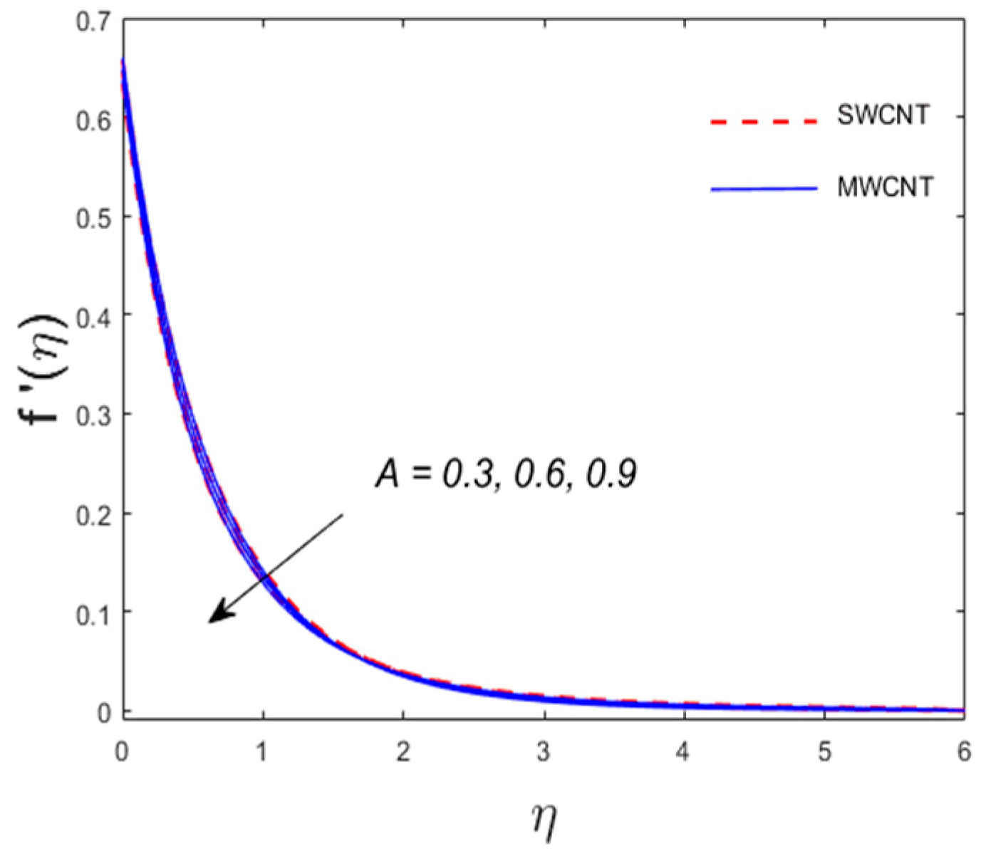
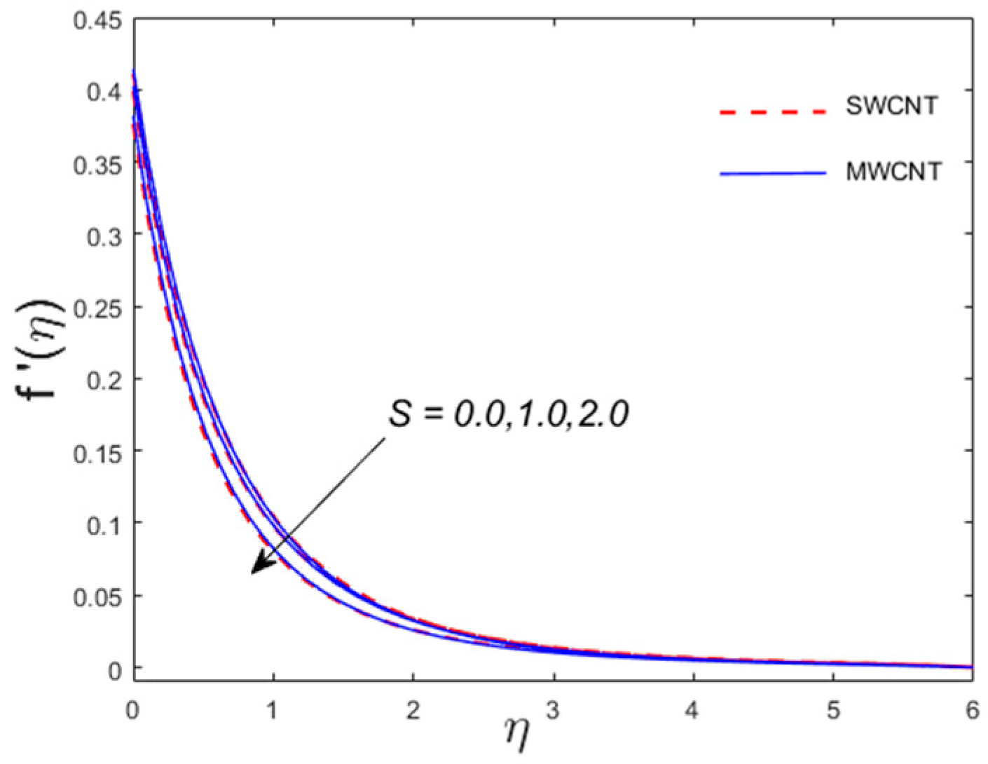
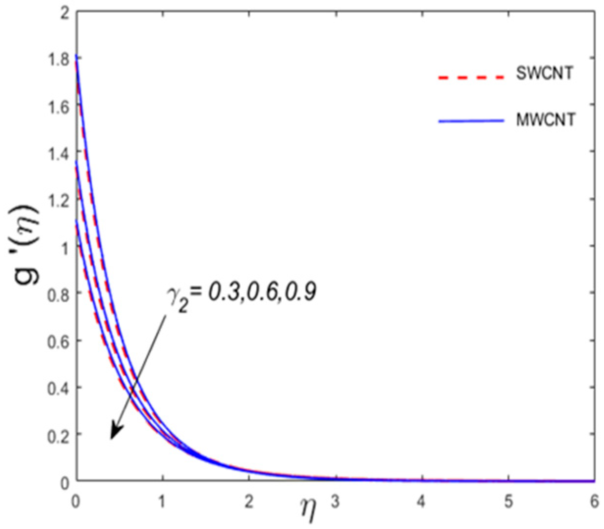
The influence of numerous suitable physical parameters on the velocity field and temperature profile are analyzed graphically in this section. Figure 2 and Figure 3 depict the features of unsteadiness factor A on the horizontal and vertical axes of velocity factors f ( η ) and g ( η ) , respectively. The velocity distribution displays diminishing behavior for larger estimates of unsteadiness factor A for velocity fields f ( η ) and g ( η ) in the case of both CNTs. Higher estimates of A indicate the reduced stretching rate in both x - and y -directions that ultimately lowers the boundary layer thickness. It is important to note that an opposite trend for both velocity components is observed for increasing A far away from the sheet. The consequence of porosity factor P m on velocity fields f ( η ) and g ( η ) is displayed in Figure 4 and Figure 5 for both CNTs. The fluid velocity reduces in both cases owing to strong impacts of Darcy’s resistance. Figure 6 is demonstrated to witness the behavior of ratio factor S on the velocity field profile f ( η ) . The velocity field and motion of the boundary layer thickness decline for numerous values of S in case of both CNTs. Physically, an enhancement in ratio factor S depicts that the x -component of velocity is less dominant than the stretching velocity in the y -direction, and as a consequence ,   f ( η ) displays diminishing trend. The impact of γ1 (velocity slip parameter) on the axial velocity f ( η ) is shown in Figure 7. It is noticed that velocity distribution is smaller with an enhancement in γ 1 . Physically, the velocity is partially shifted due to stretching because of the fluid flow, and as a result, field velocity diminishes. Performance of γ 2 (slip parameter) on the field velocity g ( η ) is demonstrated in Figure 8. For larger value of γ 2 (slip parameter) both the related thickness of boundary layer and velocity field are reduced. Indeed, the rise in the slip factor γ 2 results in escalation in the slip velocity which diminishes the fluid velocity. The impact of inertia factor F r on the velocity field is established in Figure 9. Actually, the presence of inertia coefficient with gradually improving values is to enhance resistance in flow of liquid which boosts friction near the wall, thus diminishing the velocity and making the boundary layer thinner. Figure 10 shows the influence of thermal slip factor γ3 on temperature distribution. For the larger thermal slip factor γ3 the temperature field diminishes. The incremented values of γ3 illustrate a reduction in the heat transfer rate from the wall to the neighboring fluid surfaces. Hence, the temperature of the fluid declines. Figure 11 describes the impression of thermal relaxation parameter B on the temperature field. With enhancing the estimations of B temperature field and its associated thermal boundary layer wane. Physically, the particles’ material need more opportunity to transfer heat to its adjoining particles with enhancing the thermal relaxation factor. It is perceived that for B = 0 heat transfers move rapidly all through the objects. In this way temperature field is larger for B = 0 .
Table 2 depicts the numerically calculated estimates for both skin friction coefficients [ R e x 2 ] 1 / 2 C f x and [ R e y 2 ] 1 / 2 C f y along the x - and y -directions, respectively, versus different estimates of ϕ ,   F r ,   γ 1 ,   γ 2 ,   P m , and λ for both types of CNTs. It is found that both skin friction coefficients upsurge for the gradually improving values of ϕ , F r , and P m for both CNTs, i.e., SWCNTs/MWCNTs. However, a contradictory trend is seen for γ 1 , γ 2 , and λ for both categories of CNTs. Likewise, Table 3 depicts the numerical estimates of ϕ , F r , B, γ 3 , Pm, λ , A and Pr for the Nusselt number in case of both types of CNTs. It is gathered that Nusselt number is a snowballing function of ϕ , λ , A, and Pr for CNTs. Nevertheless, a contradictory tendency is witnessed for the values of F r , B, γ 3 , and Pm.

7. Conclusions

A three-dimensional incompressible rotating nanofluid flow comprising CNTs of both categories over an exponentially stretching sheet surrounded in a Darcy–Forchheimer porous medium was studied. Further, the impact of thermal and velocity slip conditions was added and evaluated numerically utilizing a bv4c numerical scheme for the nonlinear coupled equations. The sundry parameter effects are shown graphically for both SWCNTs and MWCNTs. The presented model possesses applications in the field of optics, composite materials, nanotechnology, antifouling shade, conductive plastics, magnetic drug targeting, nuclear reactor cooling, and energy production. The salient findings of the existing study are presented below:
  • The velocity component f ( η ) decreases while g ( η ) enhances for γ 1 .
  • The velocity profiles f ( η ) and g ( η ) have the same behavior for A (unsteadiness parameter), while the opposite behavior is witnessed for the temperature profile.
  • The thickness of thermal boundary layer decreases for the values of the Prandtl number, while the rate of heat transfer is boosted.
  • The temperature shows a decreasing tendency for the thermal slip factor γ 3 .
  • The rate of shear stress increases for the inertia coefficient and porosity parameter and decreases versus the rotating factor for both SWCNT and MWCNT nanoparticles.
  • The Nusselt number declines versus thermal slip parameter and relaxation time for both CNTs.
  • The skin friction coefficients along x- and y-axes show opposite trend for the values of ϕ and P m .
  • The Nusselt number depicts similar behavior for escalating estimates of P r and λ .

Author Contributions

Funding acquisition, Data curation, J.U.R.; Formal Analysis, Software, U.K.; Investigation, Methodology, S.A.; Supervision, Writing-original draft, M.R.; Validation, M.S.; Visualization, D.L.; Writing-review & editing, S.I.

Funding

J.U.R. is supported by the CAS-TWAS President’s fellowship at USTC, China.

Conflicts of Interest

The authors declare no conflict of interest.

Nomenclature

SymbolsDescriptionGreek symbols
u along x-axis velocity componentSymbolsDescription
v along y-axis velocity component ρ f , ρ C N T density of nanoparticle
k * permeability of porous medium υ n f kinematic viscosity
F * the inertia coefficient of porous medium. μ n f dynamic viscosity
P m porosity parameter, τ w y shear stress along y-axis
Pr Prandtl number α n f modified thermal diffusivity
A unsteadiness parameter α 1 , α 2 velocity slip parameter
F r inertia coefficient α 3 thermal slip parameter.
Re x , Re y local Rayleigh number Ω constant angular velocity
S ratio parameter ( ρ c p ) n f Nanofluid heat capacity
c p Specific heat θ ( η ) Dimensionless temperature function
C f x , C f y surface drag force λ local rotation parameter
N u x Nusselt number λ E thermal relaxation time
τ w x Shear stress along x-axis

References

  1. Fourier, J. Theorie Analytique de la Chaleur; Fourier, P.M., Ed.; Chez Firmin Didot, pére et fils; Cambridge University Press: Cambridge, UK, 1822. [Google Scholar]
  2. Cattaneo, C. Sulla Conduzione del Calore; Atti Sem. Mat. Fis. Univ. Modena 3; Springer: Berlin/Heidelberg, Germany, 1948; pp. 83–101. [Google Scholar]
  3. Christov, C. On frame indifferent formulation of the Maxwell–Cattaneo model of finite-speed heat conduction. Mech. Res. Commun. 2009, 36, 481–486. [Google Scholar] [CrossRef]
  4. Oldroyd, J.G. On the formulation of rheological equations of state. Proc. R. Soc. Lond. Ser. A Math. Phys. Sci. 1950, 200, 523–541. [Google Scholar]
  5. Tibullo, V.; Zampoli, V. A uniqueness result for the Cattaneo–Christov heat conduction model applied to incompressible fluids. Mech. Res. Commun. 2011, 38, 77–79. [Google Scholar] [CrossRef]
  6. Ciarletta, M.; Straughan, B. Uniqueness and structural stability for the Cattaneo—Christov equations. Mech. Res. Commun. 2010, 37, 445–447. [Google Scholar] [CrossRef]
  7. Straughan, B. Thermal convection with the Cattaneo—Christov model. Int. J. Heat Mass Transf. 2010, 53, 95–98. [Google Scholar] [CrossRef]
  8. Alebraheem, J.; Ramzan, M. Flow of nanofluid with Cattaneo—Christov heat flux model. Appl. Nanosci. 2019, 1–11. [Google Scholar] [CrossRef]
  9. Lu, D.; Ramzan, M.; Mohammad, M.; Howari, F.; Chung, J.D. A Thin Film Flow of Nanofluid Comprising Carbon Nanotubes Influenced by Cattaneo-Christov Heat Flux and Entropy Generation. Coatings 2019, 9, 296. [Google Scholar] [CrossRef]
  10. Ramzan, M.; Bilal, M.; Chung, J.D. Influence of homogeneous-heterogeneous reactions on MHD 3D Maxwell fluid flow with Cattaneo-Christov heat flux and convective boundary condition. J. Mol. Liq. 2017, 230, 415–422. [Google Scholar] [CrossRef]
  11. Lu, D.; Li, Z.; Ramzan, M.; Shafee, A.; Chung, J.D. Unsteady squeezing carbon nanotubes based nano-liquid flow with Cattaneo–Christov heat flux and homogeneous–heterogeneous reactions. Appl. Nanosci. 2019, 9, 169–178. [Google Scholar] [CrossRef]
  12. Choi, S.U.S.; Lockwood, F.E.; Grulke, E.A.; Zhang, Z.G.; Yu, W. Anomalous thermal conductivity enhancement in nanotube suspensions. Appl. Phys. Lett. 2001, 79, 2252–2254. [Google Scholar] [CrossRef]
  13. Ramasubramaniam, R.; Chen, J.; Liu, H. Homogeneous carbon nanotube/polymer composites for electrical applications. Appl. Phys. Lett. 2003, 83, 2928. [Google Scholar] [CrossRef]
  14. Kamali, R.; Binesh, A. Numerical investigation of heat transfer enhancement using carbon nanotube-based non-Newtonian nanofluids. Int. Commun. Heat Mass Transf. 2010, 37, 1153–1157. [Google Scholar] [CrossRef]
  15. Wang, J.; Zhu, J.; Zhang, X.; Chen, Y. Heat transfer and pressure drop of nanofluids containing carbon nanotubes in laminar flows. Exp. Therm. Fluid Sci. 2013, 44, 716–721. [Google Scholar] [CrossRef]
  16. Haq, R.; Hammouch, Z.; Khan, A. Water-based squeezing flow in the presence of carbon nanotubes between two parallel disks. Therm. Sci. 2016, 20, 1973–1981. [Google Scholar] [CrossRef]
  17. Ramzan, M.; Mohammad, M.; Howari, F.; Chung, J.D. Entropy Analysis of Carbon Nanotubes Based Nanofluid Flow Past a Vertical Cone with Thermal Radiation. Entropy 2019, 21, 642. [Google Scholar] [CrossRef]
  18. Bilal, M.; Ramzan, M. Hall current effect on unsteady rotational flow of carbon nanotubes with dust particles and nonlinear thermal radiation in Darcy–Forchheimer porous media. J. Therm. Anal. Calorim. 2019, 1–11. [Google Scholar] [CrossRef]
  19. Muhammad, T.; Lu, D.-C.; Mahanthesh, B.; Eid, M.R.; Ramzan, M.; Dar, A. Significance of Darcy-Forchheimer Porous Medium in Nanofluid Through Carbon Nanotubes. Commun. Theor. Phys. 2018, 70, 361. [Google Scholar] [CrossRef]
  20. Lu, D.; Ramzan, M.; Ahmad, S.; Chung, J.D.; Farooq, U. Upshot of binary chemical reaction and activation energy on carbon nanotubes with Cattaneo-Christov heat flux and buoyancy effects. Phys. Fluids 2017, 29, 123103. [Google Scholar] [CrossRef]
  21. Hayat, T.; Haider, F.; Muhammad, T.; Alsaedi, A. Numerical treatment for Darcy-Forchheimer flow of carbon nanotubes due to an exponentially stretching curved surface. J. Central South Univ. 2019, 26, 865–872. [Google Scholar] [CrossRef]
  22. Afridi, M.I.; Qasim, M.; Wakif, A.; Hussanan, A. Second Law Analysis of Dissipative Nanofluid Flow over a Curved Surface in the Presence of Lorentz Force: Utilization of the Chebyshev—Gauss—Lobatto Spectral Method. Nanomater 2019, 9, 195. [Google Scholar] [CrossRef]
  23. Kumanek, B.; Wasiak, T.; Stando, G.; Stando, P.; Łukowiec, D.; Janas, D. Simple Method to Improve Electrical Conductivity of Films Made from Single-Walled Carbon Nanotubes. Nanomater 2019, 9, 1113. [Google Scholar] [CrossRef] [PubMed]
  24. Boscarino, S.; Filice, S.; Sciuto, A.; Libertino, S.; Scuderi, M.; Galati, C.; Scalese, S. Investigation of ZnO-decorated CNTs for UV Light Detection Applications. Nanomater 2019, 9, 1099. [Google Scholar] [CrossRef] [PubMed]
  25. Kemelbay, A.; Tikhonov, A.; Aloni, S.; Kuykendall, T.R. Conformal High-K Dielectric Coating of Suspended Single-Walled Carbon Nanotubes by Atomic Layer Deposition. Nanomater 2019, 9, 1085. [Google Scholar] [CrossRef] [PubMed]
  26. Bajpai, A.; Carlotti, S. The Effect of Hybridized Carbon Nanotubes, Silica Nanoparticles, and Core-Shell Rubber on Tensile, Fracture Mechanics and Electrical Properties of Epoxy Nanocomposites. Nanomater 2019, 9, 1057. [Google Scholar] [CrossRef] [PubMed]
  27. Forchheimer, P. Wasserbewegung durch boden. Zeitschrift fur Acker und Pflanzenbau 1901, 45, 1782–1788. [Google Scholar]
  28. Muskat, M. The Flow of Homogeneous Fluids Through Porous Media. Soil Sci. 1938, 46, 169. [Google Scholar] [CrossRef]
  29. Seddeek, M. Influence of viscous dissipation and thermophoresis on Darcy–Forchheimer mixed convection in a fluid saturated porous media. J. Colloid Interface Sci. 2006, 293, 137–142. [Google Scholar] [CrossRef] [PubMed]
  30. Pal, D.; Mondal, H. Hydromagnetic convective diffusion of species in Darcy–Forchheimer porous medium with non-uniform heat source/sink and variable viscosity. Int. Commun. Heat Mass Transf. 2012, 39, 913–917. [Google Scholar] [CrossRef]
  31. Waqas, M.; Hayat, T.; Alsaedi, A. A theoretical analysis of SWCNT–MWCNT and H2O nanofluids considering Darcy–Forchheimer relation. Appl. Nanosci. 2019, 9, 1183–1191. [Google Scholar] [CrossRef]
  32. Sadiq, M.A.; Waqas, M.; Hayat, T.; Alsaedi, A. Modeling and analysis of Maxwell nanofluid considering mixed convection and Darcy–Forchheimer relation. Appl. Nanosci. 2019, 9, 1155–1162. [Google Scholar] [CrossRef]
  33. Rashid, S.; Hayat, T.; Qayyum, S.; Ayub, M.; Alsaedi, A. Three-dimensional rotating Darcy–Forchheimer flow with activation energy. Int. J. Numer. Methods Heat Fluid Flow 2019, 29, 935–948. [Google Scholar] [CrossRef]
  34. Farooq, M.; Ahmad, S.; Javed, M.; Anjum, A. Melting heat transfer in squeezed nanofluid flow through Darcy Forchheimer medium. J. Heat Transf. 2019, 141, 012402. [Google Scholar] [CrossRef]
  35. Nasir, S.; Shah, Z.; Islam, S.; Bonyah, E.; Gul, T. Darcy Forchheimer nanofluid thin film flow of SWCNTs and heat transfer analysis over an unsteady stretching sheet. AIP Adv. 2019, 9, 015223. [Google Scholar] [CrossRef] [Green Version]
  36. Montessori, A.; Prestininzi, P.; La Rocca, M.; Succi, S. Lattice Boltzmann approach for complex nonequilibrium flows. Phys. Rev. E 2015, 92, 043308. [Google Scholar] [CrossRef] [PubMed]
  37. Montessori, A.; Amadei, C.A.; Falcucci, G.; Sega, M.; Vecitis, C.D.; Succi, S. Extended friction elucidates the breakdown of fast water transport in graphene oxide membranes. EPL 2017, 116, 54002. [Google Scholar] [CrossRef]
  38. Montessori, A.; Prestininzi, P.; La Rocca, M.; Falcucci, G.; Succi, S.; Kaxiras, E. Effects of Knudsen diffusivity on the effective reactivity of nanoporous catalyst media. J. Comput. Sci. 2016, 17, 377–383. [Google Scholar] [CrossRef] [Green Version]
Figure 1. The outline of the problem. MWCNTs: multi-wall carbon nanotubes; SWCNTs: single-wall carbon nanotubes.
Processes 07 00687 g001
Figure 2. Outcome of A vs. f ( η ) .
Processes 07 00687 g002
Figure 3. Outcome of A vs. g ( η ) .
Processes 07 00687 g003
Figure 4. Outcome of P m vs. f ( η ) .
Processes 07 00687 g004
Figure 5. Outcome of P m vs. g ( η ) .
Processes 07 00687 g005
Figure 6. Outcome of S vs. f ( η ) .
Processes 07 00687 g006
Figure 7. Outcome of γ 1 vs. f ( η ) .
Processes 07 00687 g007
Figure 8. Outcome of γ 2 vs. g ( η ) .
Processes 07 00687 g008
Figure 9. Outcome of F r vs. f ( η ) .
Processes 07 00687 g009
Figure 10. Outcome of γ 3 vs. θ ( η ) .
Processes 07 00687 g010
Figure 11. Outcome of B vs. θ ( η ) .
Processes 07 00687 g011
Table 1. Thermophysical attributes of the base fluid (engine oil), SWCNTs, and MWCNTs.
Physical PropertiesBase FluidNanoparticles
Engine oilMWCNTsSWCNTs
Cp (J/kgK)1910796425
ρ (kg/m3)88416002600
K (W/mK)0.14430006600
Table 2. Numerical value of skin friction for engine oil base fluid for various parameters.
ϕ F r γ 1 γ 2 P m λ [ R e x 2 ] 1 / 2 C f x [ R e y 2 ] 1 / 2 C f y
SWCNTsMWCNTsSWCNTsMWCNTs
0.00.10.10.20.30.11.69161.69161.42861.4286
0.05 1.90141.86981.60871.5861
0.1 2.15491.97541.81691.7696
0.2 1.9211.8891.62111.5983
0.4 1.95921.92631.64521.6220
0.6 1.9961.96241.66831.6448
0.2 1.59261.57021.59261.5702
0.3 1.37411.35731.58061.5583
0.4 1.21051.19731.57121.5490
0.2 1.90141.86981.60871.5861
0.3 1.88421.85291.38591.3690
0.4 1.87091.83971.21941.2062
0.3 1.90141.86981.60871.5861
0.5 1.93771.90711.63571.6140
0.7 1.9731.94331.66181.6409
0.11.90141.86981.60871.5861
0.31.76941.74091.47911.4594
0.41.69451.66771.40871.3906
Table 3. Local Nusselt number for engine oil base fluid for various parameters.
ϕ F r B γ 3 P m λ A P r [ R e x 2 ] 1 / 2 N u x
SWCNTsMWCNTs
0.00.10.110.30.10.210.45150.4515
0.05 1.19441.1139
0.1 2.48952.2247
0.2 1.19241.1120
0.4 1.18861.1084
0.6 1.18521.1051
0.2 1.14251.0647
0.3 1.11431.0388
0.4 1.09871.0250
1 1.19441.1139
1.3 1.01800.9515
1.5 0.92670.8673
0.3 1.19441.1139
0.5 1.18531.1049
0.7 1.77201.0969
0.1 1.19441.1139
0.3 1.23301.1489
0.4 1.26301.1772
0.2 1.19441.1139
0.4 1.35891.2734
0.6 1.45731.3690
11.19441.1139
1.31.26441.1808
1.51.30161.2163